lme73.000 / pme73.840 gas pilot ignition with only one ... oct 2014 a7105.28en.pdf · recommended...
TRANSCRIPT

Software Version V02.00 CC1A7105.28en 29.09.2014
Building Technologies DivisionInfrastructure & Cities Sector
Presentation example PME7... Presentation example LME7...
LME73.000... / PME73.840... Burner control Gas pilot ignition with only one pilot valve User Documentation Application: - 1-stage, without actuator
- 1-stage or modulating, direct or pilot ignited forced draft burner - Integrated actuator control (parameterized) via 3-position controller - Integrated valve proving (can be parameterized) - e.g. for burners to EN 676
The PME7... and this User Documentation are intended for use by OEMs which integrate the LME7... with PME7... in their products.
Note! This documentation is only valid together with LME7... Basic Documentation P7105!

2/22
Building Technologies Division User Documentation PME73.840... CC1A7105.28en Infrastructure & Cities Sector Contents 29.09.2014
Contents 1 Supplementary documentation .................................................................... 3
2 Warning notes ................................................................................................ 4
3 Typographical conventions .......................................................................... 4
4 Program sequence PME73.840... .................................................................. 5
5 List of phase display ..................................................................................... 6
6 Gas pilot ignition 1 (Gp1/2) with only one pilot valve, 1-stage, with valve proving ............................................................................................................ 8
7 Valve proving with separate pressure switch ............................................. 9
8 Input gas pressure switch-min ................................................................... 11
9 Connection diagram for LME73.000... with actuator SQM4... .................. 12
9.1 Connection diagram for LME73.000... without actuator ................................. 13
10 Time table and settings ............................................................................... 14
11 Inputs and outputs / internal connection diagram ................................... 16
12 Parameter list (AZL2...) ................................................................................ 17
13 Legend .......................................................................................................... 21
14 List of figures ............................................................................................... 22

3/22
Building Technologies Division Unser Documentation PME73.840... CC1A7105.28en Infrastructure & Cities Sector 1 Supplementary documentation 29.09.2014
1 Supplementary documentation Type of product Type of documentation Document number LME… Environmental Product
Declaration E7105
PME… Environmental Product Declaration
E7105.1
LME7... Data Sheet N7105 LME... Product overview Q7010 LME7 Basic Documentation P7105
4/22
Building Technologies Division User Documentation PME73.840... CC1A7105.28en Infrastructure & Cities Sector 2 Warning notes 29.09.2014
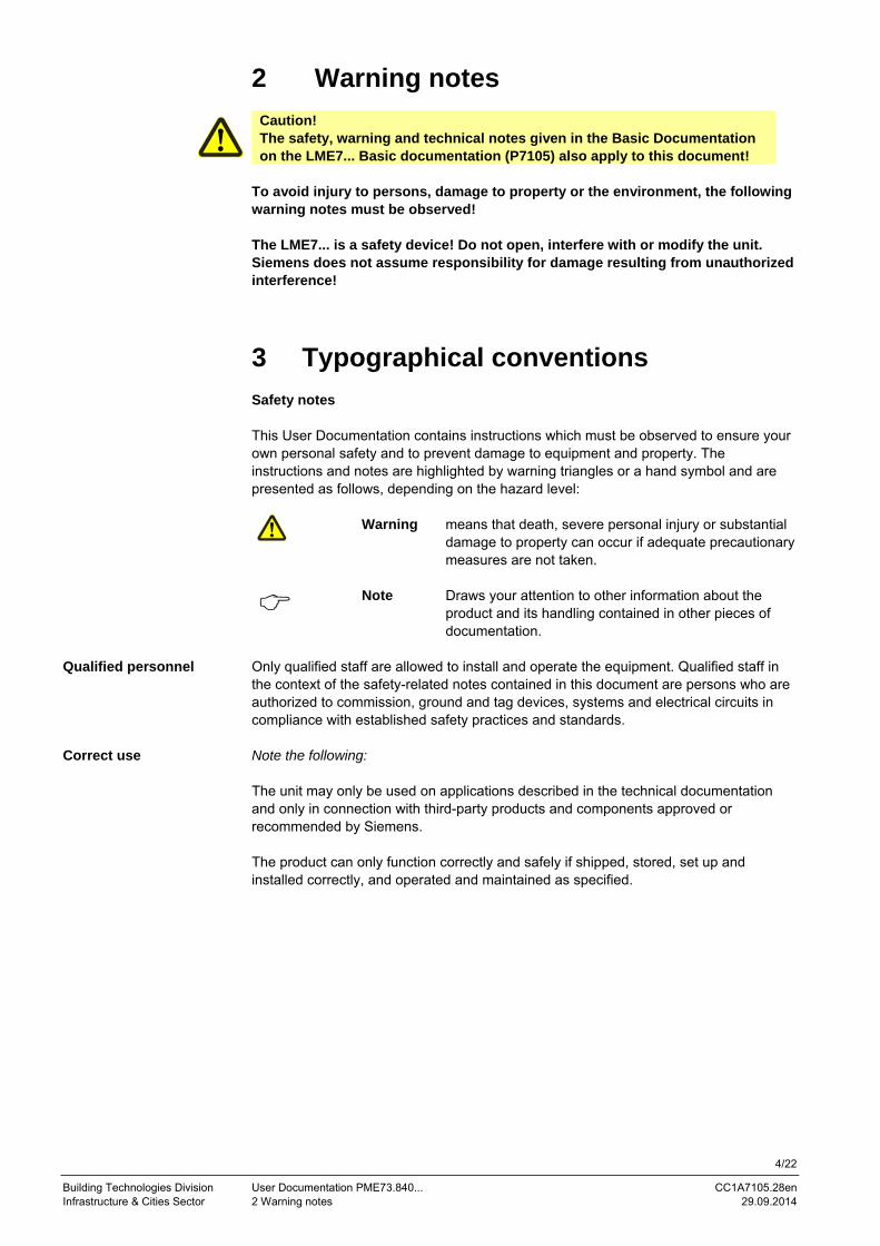
2 Warning notes
Caution! The safety, warning and technical notes given in the Basic Documentation on the LME7... Basic documentation (P7105) also apply to this document!
To avoid injury to persons, damage to property or the environment, the following warning notes must be observed! The LME7... is a safety device! Do not open, interfere with or modify the unit. Siemens does not assume responsibility for damage resulting from unauthorized interference!
3 Typographical conventions Safety notes This User Documentation contains instructions which must be observed to ensure your own personal safety and to prevent damage to equipment and property. The instructions and notes are highlighted by warning triangles or a hand symbol and are presented as follows, depending on the hazard level:
Warning means that death, severe personal injury or substantial
damage to property can occur if adequate precautionary measures are not taken.
Note Draws your attention to other information about the product and its handling contained in other pieces of documentation.
Only qualified staff are allowed to install and operate the equipment. Qualified staff in the context of the safety-related notes contained in this document are persons who are authorized to commission, ground and tag devices, systems and electrical circuits in compliance with established safety practices and standards. Note the following: The unit may only be used on applications described in the technical documentation and only in connection with third-party products and components approved or recommended by Siemens. The product can only function correctly and safely if shipped, stored, set up and installed correctly, and operated and maintained as specified.
Qualified personnel
Correct use

5/22
Building Technologies Division Unser Documentation PME73.840... CC1A7105.28en Infrastructure & Cities Sector 4 Program sequence PME73.840... 29.09.2014
4 Program sequence PME73.840... → For connection diagram fuel train G/Gp1/1/Gp1/2
Standby
Actu
ator
pos
ition High-fire
CLOSE
Relaycontact Function / inputs
Operation unit parameter number
LED permanent
LED flashing
Startup Operation Shutdown Valve provingif parameter
241.00 =1 (ON)can be
parameterized
Relaycontact Function / outputs
Phase number 7 segment in the LME...
Input Dbr3 for PV
Output PV
Phase number AZL2...
7105d102e/0814
M
Z
V1
V2
AL
K1X2-02 Pin 3
Ignition load / low-fire
R
LR-AUF
LR-ZU
LP
Pmin
P LT
ION / QRA
X3-04 Pin 5
tw t11 t10 t12 t3 t3n t4 t11 td4 td1 td3 td2
t1 TSA
224 225 226 257 230 231 232 234
SKX3-04 Pin 1
X5-03 Pin 1
X5-03 Pin 3
X65 Pin 1
X5-03 Pin 2
X65 Pin 1
X3-02 Pin 1
X5-01 Pin 2
X2-02 Pin 4
X9-04 Pin 2
PV
SVK1X6-03 Pin 3
K4X2-01 Pin 3
K5X4-02 Pin 3
K2/2X7-01 Pin 3
K7X7-04 Pin 4
X7-02 Pin 3
K2/1X2-03 Pin 3
21 22 24 22 30 30 38 40 42 44 50 50 72 74 10 80 81 82 83
t9 t5
SA-NLK11X2-09 Pin 3
SA-KLK12X2-09 Pin 2
SA-ZUX2-09 Pin 1
SA-RX2-09 Pin 4
X2-09 Pin 8
X2-09 Pin 7
36
260
t22
74
t8
242 243 244 245259
POC
POC
*) *) *) *)K4
K2/2
21 22 24 22 30 30 38 40 42 44 50 50 72 74 10 80 81 82 83 36 74
240240240240240240
t11 t12
*1*2
Figure 1: Program sequence
*) During the actuator’s running phases, the actuator’s feedback signal must first be OFF, then ON
6/22
Building Technologies Division User Documentation PME73.840... CC1A7105.28en Infrastructure & Cities Sector 5 List of phase display 29.09.2014
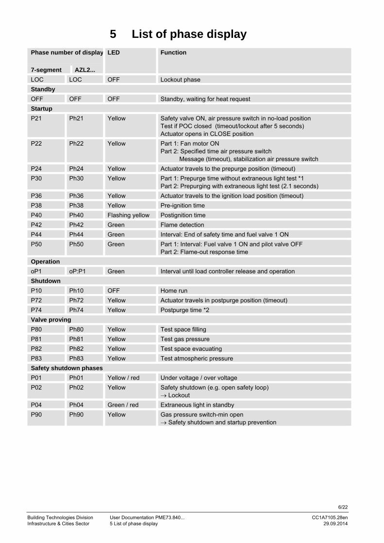
5 List of phase display
Phase number of display
LED Function
7-segment AZL2... LOC LOC OFF Lockout phase Standby OFF OFF OFF Standby, waiting for heat request Startup P21 Ph21 Yellow Safety valve ON, air pressure switch in no-load position
Test if POC closed (timeout/lockout after 5 seconds) Actuator opens in CLOSE position
P22 Ph22 Yellow Part 1: Fan motor ON Part 2: Specified time air pressure switch Message (timeout), stabilization air pressure switch
P24 Ph24 Yellow Actuator travels to the prepurge position (timeout) P30 Ph30 Yellow Part 1: Prepurge time without extraneous light test *1
Part 2: Prepurging with extraneous light test (2.1 seconds) P36 Ph36 Yellow Actuator travels to the ignition load position (timeout) P38 Ph38 Yellow Pre-ignition time P40 Ph40 Flashing yellow Postignition time P42 Ph42 Green Flame detection P44 Ph44 Green Interval: End of safety time and fuel valve 1 ON P50 Ph50 Green Part 1: Interval: Fuel valve 1 ON and pilot valve OFF
Part 2: Flame-out response time Operation oP1 oP:P1 Green Interval until load controller release and operation Shutdown P10 Ph10 OFF Home run P72 Ph72 Yellow Actuator travels in postpurge position (timeout) P74 Ph74 Yellow Postpurge time *2 Valve proving P80 Ph80 Yellow Test space filling P81 Ph81 Yellow Test gas pressure P82 Ph82 Yellow Test space evacuating P83 Ph83 Yellow Test atmospheric pressure Safety shutdown phases P01 Ph01 Yellow / red Under voltage / over voltage P02 Ph02 Yellow Safety shutdown (e.g. open safety loop)
→ Lockout P04 Ph04 Green / red Extraneous light in standby P90 Ph90 Yellow Gas pressure switch-min open
→ Safety shutdown and startup prevention

7/22
Building Technologies Division Unser Documentation PME73.840... CC1A7105.28en Infrastructure & Cities Sector 5 List of phase display 29.09.2014
*1 Valve proving during prepurging, if
- Parameter 241.00 = 1 and Parameter 241.02 = 1 or - Parameter 241.00 = 1 and Parameter 241.01 = 0 or - Parameters 234 (Postpurge time) = 0 seconds
*2 Valve proving during postpurging, if - Parameter 241.00 = 1 and Parameter 241.02 = 1 or - Parameters 241.00 = 1 and Parameter 241.01 = 1 and - Parameters 234 (Postpurge time) = >0 seconds

8/22
Building Technologies Division User Documentation PME73.840... CC1A7105.28en Infrastructure & Cities Sector 6 Gas pilot ignition 1 (Gp1/2) with only one pilot valve, 1-stage, with valve proving 29.09.2014
6 Gas pilot ignition 1 (Gp1/2) with only one pilot valve, 1-stage, with valve proving
SV V1
Program Gp1/2 Gas pilot 1, 1-stage
PV
X7-01 X7-04V2
X7-02
LME73.000...
X9-04
Note!To prevent plant malfunctions, always use an NC contact for pressure switch valve proving (P LT)!
Detail
Figure 2: Gas pilot ignition 1 (Gp1/2), 1-stage, with valve proving
Note! Here – contrary to the information given in the User Documentation (A7105.27) – fuel valve 1 is to be connected to terminal strip X7-02 and fuel valve 2 to terminal strip X7-04.
Legend Pmax Pressure switch-max Pmin Pressure switch-min P LT Pressure switch valve proving SV Safety valve V... Fuel valve

9/22
Building Technologies Division Unser Documentation PME73.840... CC1A7105.28en Infrastructure & Cities Sector 7 Valve proving with separate pressure switch 29.09.2014
7 Valve proving with separate pressure switch
P LT
7105d103e/0814
PLT
Figure 3: Valve proving with separate pressure switch
Step 1: td4 Test space filling The gas valve on the mains side is opened to fill the gas pipe. Step 2: td1 Test gas pressure The gas valve is closed whereupon the pressure in the test space must exceed a certain level. Step 3: td3 Test space evacuating The gas valve on the burner side is opened to take the test space to atmospheric pressure. Step 4: td2 Test atmospheric pressure When the gas valve is closed, the gas pressure must drop below a certain level. Legend td1 Test gas pressure td2 Test atmospheric pressure td3 Test space evacuating td4 Test space filling V... Fuel valve P LT Pressure switch valve proving
Input/output signal 1 (ON) Input/output signal 0 (OFF) Input permissible signal 1 (ON) or 0 (OFF)
Query logic of gas pressure switch for gas valve proving: • Gas pressure present pressure switch open • Gas pressure not present pressure switch closed
No. Parameter
241.00 Valve proving 0 = OFF 1 = ON ¹)
242 Valve proving (time td4) test space filling 243 Valve proving (time td1) test gas pressure 244 Valve proving (time td3) test space evacuating 245 Valve proving (time td2) test atmospheric pressure
¹) Valve proving during postpurging, if parameter 234 >0 (postpurge time) and parameter 241.01 = 1

10/22
Building Technologies Division User Documentation PME73.840... CC1A7105.28en Infrastructure & Cities Sector 7 Valve proving with separate pressure switch 29.09.2014
Program sequence with gas valve proving Gas valve proving during startup is performed only after a reset from the lockout position, after power ON, and when parameter 234 = 0 seconds. In that case, gas valve proving takes place at the same time as prepurging. This means that the prepurge time corresponds to at least the sum of all 4 gas valve proving parameters (242, 243, 244, and 245). Gas valve proving during shutdown is performed only if the postpurge time >0 (Parameter 234 >0). If no postpurge time is parameterized, gas valve proving takes place during startup when prepurging. During shutdown (heat request OFF), it is checked if parameter 241.00 = 1 (gas valve proving ON) and parameter 234 ≠ 0 seconds before the valves close. This means that, first, fuel valve 1 is closed. Fuel valve 2 remains open so that the remaining gas in the test space can be burned. The postpurge time runs at the same time as gas valve proving. This means that the postpurge time corresponds to at least the sum of all 4 gas valve proving parameters (242, 243, 244, and 245). Before prepurging and valve proving, the actuator opens in high-fire position.
Caution! The OEM must set the evacuation, filling and test times for atmospheric or mains pressure on every plant in compliance with the requirements of EN 1643. If not observed, there is a risk of impairment of safety functions.
It must be ensured that the 2 test times are correctly set. It is to be checked whether the gas required for the test may be fed into the combustion chamber (on the relevant application). The test times are safety-related. After a reset and in the case of aborted or prevented valve proving, the unit will perform valve proving the next time it is started up (only when valve proving is activated). In the case of valve proving, prepurging is active during the startup phase, even if it has been deactivated. Examples of aborted valve proving: When the safety loop or the start prevention input for gas (containing pressure switch-min) opens during valve proving. Valve proving – calculation of leakage rate (PG - Pw) • V • 3600 ttest = ⎯⎯⎯⎯⎯⎯⎯⎯⎯
Patm • QLeck QLeck in l/h Leakage rate in liters per hour PG in mbar Overpressure between the valves at the beginning of the test phase PW in mbar Overpressure set on the pressure switch (normally 50 % of the gas inlet pressure) Patm in mbar Absolute air pressure (1013 mbar normal pressure) V in l Volume between the valves (test volume) including valve volume Valve volume and pilot pipe, if present ttest in s test time
During startup
During shutdown

11/22
Building Technologies Division Unser Documentation PME73.840... CC1A7105.28en Infrastructure & Cities Sector 8 Input gas pressure switch-min 29.09.2014
8 Input gas pressure switch-min If gas pressure switch-min fails, safety shutdown and start prevention will be initiated, until the gas pressure switch-min closes again. During the start prevention the yellow LED lights up and the safety loop is active. Burner control is in Phase 90.
Behavior in the event gas pressure switch-min fails (terminal X5-01 pin 2 and pin 3)
12/22
Building Technologies Division User Documentation PME73.840... CC1A7105.28en Infrastructure & Cities Sector 9 Connection diagram for LME73.000... with actuator SQM4... 29.09.2014
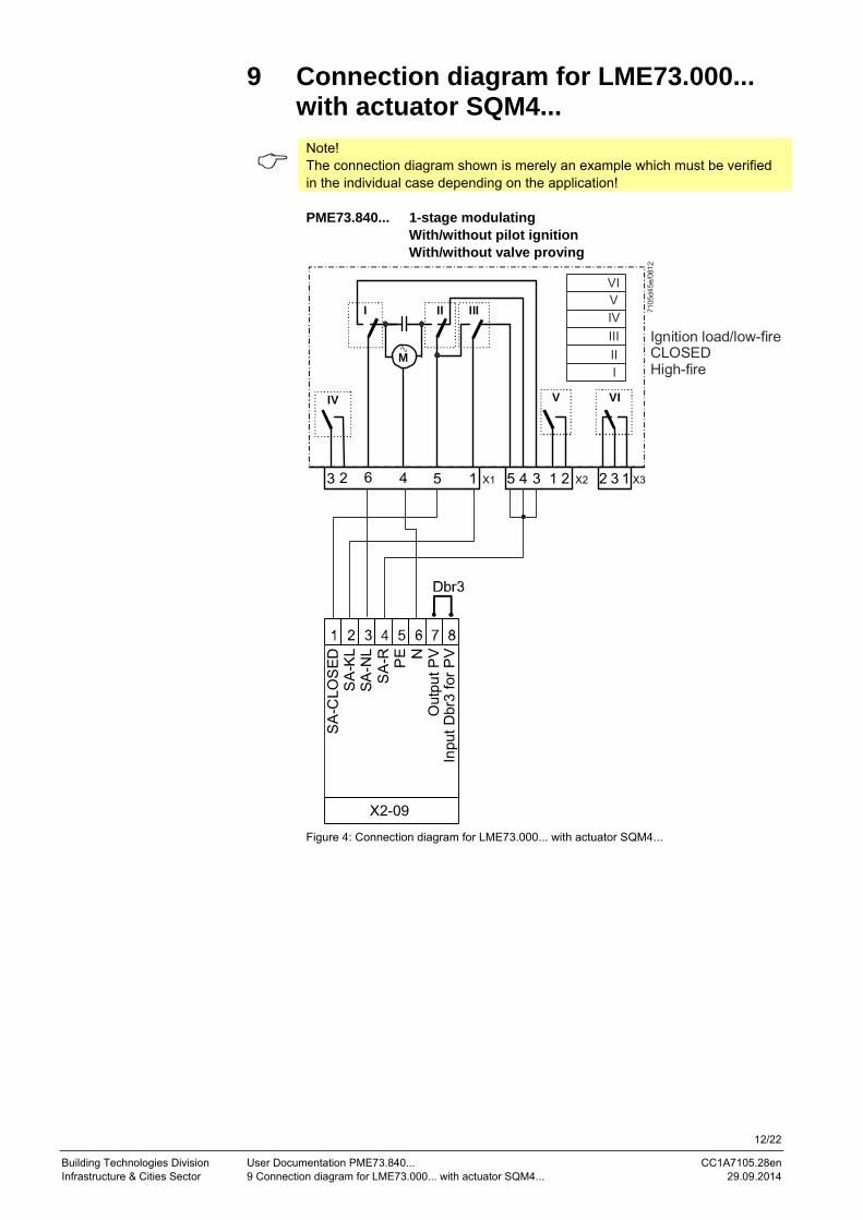
9 Connection diagram for LME73.000... with actuator SQM4...
Note! The connection diagram shown is merely an example which must be verified in the individual case depending on the application!
PME73.840... 1-stage modulating
With/without pilot ignition With/without valve proving
X3X2X1 12 3
VIV
III
5
M
III
VI
2134123 4 56
I
VIVIVIIIII
7105
d45e
/081
2
X2-09
SA
-CLO
SED
SA
-KL
SA-N
LS
A-R PE
Inpu
t Dbr
3 fo
r PV
Out
put P
V
Ignition load/low-fireCLOSEDHigh-fire
Figure 4: Connection diagram for LME73.000... with actuator SQM4...

13/22
Building Technologies Division Unser Documentation PME73.840... CC1A7105.28en Infrastructure & Cities Sector 9 Connection diagram for LME73.000... with actuator SQM4... 29.09.2014
9.1 Connection diagram for LME73.000... without actuator
Note! The connection diagram shown is merely an example which must be verified in the individual case depending on the application!
PME73.840... 1-stage
With/without pilot ignition With/without valve proving Without actuator
X2-09
SA-
CLO
SESA
-KL
SA
-NL
SA-R PE
Inpu
t Dbr
3 fo
r PV
Out
put P
V
7105
d38e
/031
2
Figure 5: Connection diagram for LME73.000... without actuator SQM4...
• When using the LME73.000... without actuator according to application Gas direct
ignition (G), 1-stage or gas direct ignition 1 (G), 1-stage, with valve proving, wire link Dbr4 must be fitted to the actuator connector terminal X2-09 as shown in the figure above
• Parameter 515.01 must be set to 0

14/22
Building Technologies Division User Documentation PME73.840... CC1A7105.28en Infrastructure & Cities Sector 10 Time table and settings 29.09.2014
10 Time table and settings Type Times in seconds
PME73.840... tw TSA max.
t1 P225 4) min.
t3 P226 min.
t3n P257 approx.
t4 P230 min.
t5 P232 min.
t8 P234 5) min.
t9 P231 approx.
t10 P224 approx.
t11 P259 approx.
t12 P260 approx.
t22 1) 2) 3)
td1 P243 td2
P245 min.
td3 P244 td4
P242 max.
Requirements 2.5 3 30 6 2.5 9 8.5 15 3 15 300 300 t9+1 --- --- --- 10 3 Factory setting --- t3n+0.45 29.106+2.1 6.174 2.205+0.3 9.408 8.82 19.404 2.646 13.818 300.762 300.762 --- --- --- --- 10.29 2.646 Max. 2.5 14 1237+2.1 37.485 13.23+0.3 74.97 74.97 1237 74.97 13.818 1237 1237 --- 1 0.45 0.45 37.485 2.646 Min. --- --- 0+2.1 1.029 0+0.3 3.234 2.058 0 0 0 0 0 --- 0.3 0.3 --- 1.029 0 Step size --- --- 4.851 0.147 0.147 0.294 0.294 4.851 0.294 0.294 4.851 4.851 --- --- --- --- 0.147 0.147 Function parameter Parameter number Factory setting Repetition in the event of loss of flame during operation 0: None 1: None 2: 1 x repetition
240 0
Valve proving 0: OFF 1: ON
241.00 1
Valve proving 0: During prepurge time 1: During postpurge time
241.01 1
Valve proving 0: see parameter 241.01 1: During prepurge time and postpurge time
241.02 0
Actuator position during prepurge time and postpurge time 0: Purging in low-fire 1: Purging in high-fire
515.00 1
Application with/without actuator 0: Without actuator 1: With actuator
515.01 1
Continuous pilot (during operation) 0: OFF 1: ON
247 0
15/22
Building Technologies Division User Documentation PME73.840... CC1A7105.28en Infrastructure & Cities Sector 10 Time table and settings 29.09.2014
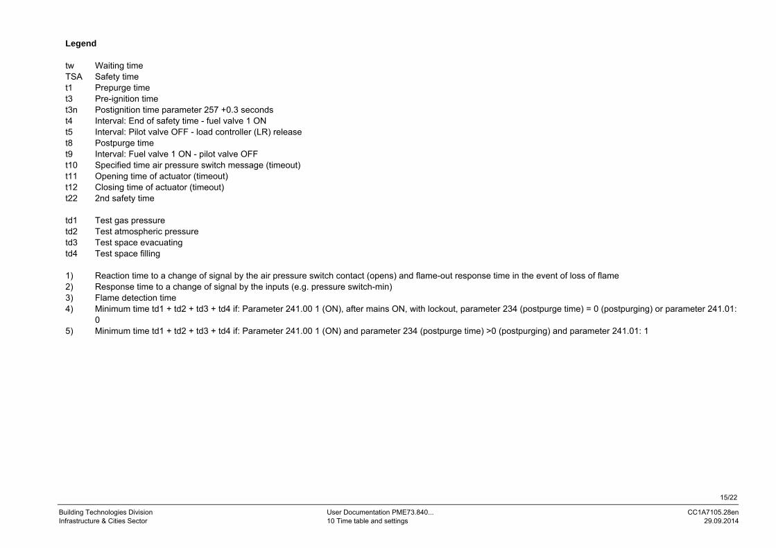
Legend tw Waiting time TSA Safety time t1 Prepurge time t3 Pre-ignition time t3n Postignition time parameter 257 +0.3 seconds t4 Interval: End of safety time - fuel valve 1 ON t5 Interval: Pilot valve OFF - load controller (LR) release t8 Postpurge time t9 Interval: Fuel valve 1 ON - pilot valve OFF t10 Specified time air pressure switch message (timeout) t11 Opening time of actuator (timeout) t12 Closing time of actuator (timeout) t22 2nd safety time td1 Test gas pressure td2 Test atmospheric pressure td3 Test space evacuating td4 Test space filling 1) Reaction time to a change of signal by the air pressure switch contact (opens) and flame-out response time in the event of loss of flame 2) Response time to a change of signal by the inputs (e.g. pressure switch-min) 3) Flame detection time 4) Minimum time td1 + td2 + td3 + td4 if: Parameter 241.00 1 (ON), after mains ON, with lockout, parameter 234 (postpurge time) = 0 (postpurging) or parameter 241.01:
0 5) Minimum time td1 + td2 + td3 + td4 if: Parameter 241.00 1 (ON) and parameter 234 (postpurge time) >0 (postpurging) and parameter 241.01: 1

16/22
Building Technologies Division User Documentation PME73.840... CC1A7105.28en Infrastructure & Cities Sector 11 Inputs and outputs / internal connection diagram 29.09.2014
11 Inputs and outputs / internal connection diagram
7105d59e/0914
X7-
01
03K
34
X4-
02
03K
66
X10
-05
05K
37
X10
-06
02K4
3
X3-0
4
05K
30
X6-
03
03K5
7
X2-0
1
03K
105
X3-0
2
02K
02
X5-
01
03K
54
X9-
04
03K
30
X56
GN
D
X7-
04
04K
77
X2-
03
03K1
5
X5-
03
03K
105
X2-
02
04K2
204
K01
CodingPlug marking
NT
N
L
LME73.000...
LED
K12
K11
K9
K2/2
K7
K5
FSV2
FSV1
K4
K1K2/1
SA-NL
SA-Z
X7-
02
03K
10
X2-
09
08K2
4
X76
Not
use
d
X66X65
µC
+
-
A
BCI
Output pilot valve PV
Output alarm
Feedback input POC
Output fuel valve V1
Dbr
3
Not active
P LT
Dbr
2 fo
rdi
rect
igni
tion
Not
use
d
Dbr
4 **
)
Not
use
d
/reset
Note!*) If POC not used, the wire link Dbr1 must be connected!**) For applicatins without actuator SQM4..., the wire link Dbr4 must be connected!
BCI
Figure 6: Inputs and outputs/internal connection diagram

17/22
Building Technologies Division User Documentation PME73.840... CC1A7105.28en Infrastructure & Cities Sector 12 Parameter list (AZL2...) 29.09.2014
12 Parameter list (AZL2...) Parameter- number
Parameter Edit Value range Resolution Factory setting Password level reading from level
Password level writing from level Min. Max.
000 Internal parameter 41 Heating engineer's password (4 characters) Edit xxxx xxxx --- --- --- OEM 42 OEM's password (5 characters) Edit xxxxx xxxxx --- --- --- OEM 60 Backup/restore Edit Restore Backup --- --- --- SO 100 General 102 Identification date Read only --- --- --- --- Info --- 103 Identification number Read only 0 9999 1 0 Info --- 113 Identification of burner Edit x xxxxxxxx 1 burnErId Info SO 140 Mode display of display and operating unit AZL2...
1: Standard (program phase) 2: Flame 1 (QRA.../ION) 3: Flame 2 (QRB.../QRC...) not used 4: Active power (power value)
Edit 1 4 1 1 SO SO
164 Number of startups resettable Resettable 0 999999 1 0 Info Info 166 Total number of startups Read only 0 999999 1 0 Info --- 170.00 Switching cycles relay contact K12 Read only 0 999999 1 0 Info --- 170.01 Switching cycles relay contact K11 Read only 0 999999 1 0 Info --- 170.02 Switching cycles relay contact K2 Read only 0 999999 1 0 Info --- 170.03 Switching cycles relay contact K1 Read only 0 999999 1 0 Info --- 171 Max. Max. switching cycles relay Read only 0 999999 1 0 Info ---

18/22
Building Technologies Division User Documentation PME73.840... CC1A7105.28en Infrastructure & Cities Sector 12 Parameter list (AZL2...) 29.09.2014
Parameter- number
Parameter Edit Value range Resolution Factory setting Password level reading from level
Password level writing from level Min. Max.
200 Burner control 224 Specified time air pressure switch Edit 0 s 13.818 s 0.294 s 13.818 s SO OEM 225 Prepurge time -2.1 seconds Edit 0 s 1237 s 4.851 s 29.106 s SO OEM 226 Pre-ignition time Edit 1.029 s 37.485 s 0.147 s 6.174 s SO OEM 230 Interval: End of safety time - fuel valve 1 ON Edit 3.234 s 74.97 s 0.294 s 9.408 s SO OEM 231 Interval: Fuel valve 1 ON - pilot valve OFF Edit 0 s 74.97 s 0.294 s 2.646 s SO OEM 232 Interval: Pilot valve OFF - load controller (LR) release Edit 2.058 s 74.97 s 0.294 s 8.820 s SO OEM 234 Postpurge time Edit 0 s 1237 s 4.851 s 19.404 s SO OEM 240 Repetition in the event of loss of flame during operation
0: None 1: None 2: 1 x repetition
Edit 0 2 1 0 SO OEM
241.00 Valve proving 0: OFF 1: ON
Edit 0 1 1 1 SO OEM
241.01 Valve proving 0: During prepurge time 1: During postpurge time
Edit 0 1 1 1 SO OEM
241.02 Valve proving 0: see parameter 241.01 1: During prepurge time and postpurge time
Edit 0 1 1 0 SO OEM
242 Valve proving test space filling Edit 0 s 2.648 s 0.147 s 2.648 s SO OEM 243 Valve proving time test gas pressure Edit 1.029 s 37.485 s 0.147 s 10.290 s SO OEM 244 Valve proving test space evacuating Edit 0 s 2.648 s 0.147 s 2.648 s SO OEM 245 Valve proving time test atmospheric pressure Edit 1.029 s 37.485 s 0.147 s 10.290 s SO OEM 247 Continuous pilot (during operation)
0: OFF 1: ON
Edit 0 1 1 0 SO OEM
257 Postignition time -0.3 seconds Edit 0 s 13.23 s 0.147 s 2.205 s SO OEM 259 Opening time of actuator (timeout) Edit 0 s 1237 s 4.851 s 300.762 s SO OEM 260 Closing time of actuator (timeout) Edit 0 s 1237 s 4.851 s 300.762 s SO OEM 515.00 Actuator position during prepurge time and postpurge time
0: Purging in low-fire 1: Purging in high-fire
Edit 0 1 1 1 SO OEM
515.01 Application with/without actuator 0: Without actuator 1: With actuator
Edit 0 1 1 1 SO OEM

19/22
Building Technologies Division User Documentation PME73.840... CC1A7105.28en Infrastructure & Cities Sector 12 Parameter list (AZL2...) 29.09.2014
Parameter- number
Parameter Edit Value range Resolution Factory setting Password level Password level Min. Max. reading from level writing from level
700 Error history 701 Current error:
00: Error code 01: Startup meter reading 02: HMI phase 03: Power value
Read only 2 0 --- 0%
255 999999 --- 100%
1 1 --- 1
--- Service ---
702 Error history former 1: 00: Error code 01: Startup meter reading 02: HMI phase 03: Power value
Read only 2 0 --- 0%
255 999999 --- 100%
1 1 --- 1
--- Service ---
• • • 711 Error history former 10:
00: Error code 01: Startup meter reading 02: HMI phase 03: Power value
Read only 2 0 --- 0%
255 999999 --- 100%
1 1 --- 1
--- Service ---
900 Process data 936 Normalized speed Read only 0% 100% 0.01% --- Service --- 951 Mains voltage Read only 0 V LME73.000A1: 175 V
LME73.000A2: 350 V 1 V --- Service ---
954 Flame intensity Read only 0% 100% 1% --- Service ---

20/22
Building Technologies Division User Documentation PME73.840... CC1A7105.28en Infrastructure & Cities Sector 12 Parameter list (AZL2...) 29.09.2014
Error code list
Error code Clear text Possible cause
AZL2... 7-segment
Loc: 2 Loc 2 No Flame at end of safety time Safety time
- Faulty or soiled fuel valves - Faulty or soiled flame detector - Poor adjustment of burner, no fuel - Faulty ignition equipment
Loc: 3 Loc 3
Air pressure failure (air pressure switch has welded in the no-load position, drop-out after specified time) (air pressure switch flame-on response time)
Air pressure switch faulty - Loss of air pressure signal after specified time - Air pressure switch has welded in no-load position
Loc: 4 Loc 4 Extraneous light Extraneous light during burner startup
Loc: 5 Loc 5 Air pressure faulty, air pressure switch welded in working position
Time supervision air pressure switch - Air pressure switch has welded in working position
Loc: 6 Loc 6 Fault of actuator - Actuator faulty or blocked - Faulty connection - Wrong adjustment
Loc: 7 Loc 7 Loss of flame
Too many losses of flame during operation (Limitation of the number of repetitions) - Faulty or soiled fuel valves - Faulty or soiled flame detector - Poor adjustment of burner
Loc: 10 Loc 10: Error not relatable (application) Internal error
Wiring error or internal error, output contacts, other faults
Loc: 12 Loc 12 Valve proving Fuel valve 2 leak Loc: 13 Loc 13 Valve proving Fuel valve 1 leak Loc: 14 Loc 14 POC error Error valve's closing control POC
Loc: 22 Loc 22 Safety loop open - Gas pressure switch-max open - Safety limit thermostat cut out
Loc: 138 Loc 138 Restore process successful Restore process successful Loc: 139 Loc 139 No program module detected No program module plugged in Loc: 167 Loc 167 Manual locking Manual locking Loc: 206 Loc 206 AZL2... incompatible Use the latest version
rSt Er1 rSt Er1 Error in compatibility program module to basic unit during restore process
Program sequence of program module does not match the basic unit
rSt Er2 rSt Er2 Error in compatibility program module to basic unit during restore process
Hardware of basic unit does not match the program module
rSt Er3 rSt Er3 Error during restore process - Program module faulty - Program module removed during restore process
bAC Er3 bAC Er3 Fault of compatibility program module to basic unit during backup process
Program sequence of program module does not match the basic unit
Err PrC Err PrC Fault of program module - Error in data content of program module - No program module fitted
21/22
Building Technologies Division User Documentation PME73.840... CC1A7105.28en Infrastructure & Cities Sector 13 Legend 29.09.2014
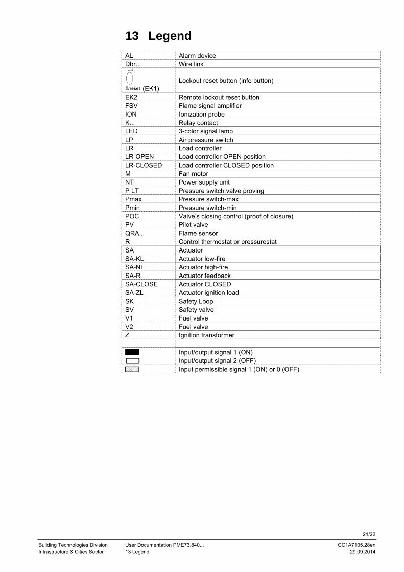
13 Legend AL Alarm device Dbr... Wire link
/reset (EK1) Lockout reset button (info button)
EK2 Remote lockout reset button FSV Flame signal amplifier ION Ionization probe K... Relay contact LED 3-color signal lamp LP Air pressure switch LR Load controller LR-OPEN Load controller OPEN position LR-CLOSED Load controller CLOSED position M Fan motor NT Power supply unit P LT Pressure switch valve proving Pmax Pressure switch-max Pmin Pressure switch-min POC Valve’s closing control (proof of closure) PV Pilot valve QRA... Flame sensor R Control thermostat or pressurestat SA Actuator SA-KL Actuator low-fire SA-NL Actuator high-fire SA-R Actuator feedback SA-CLOSE Actuator CLOSED SA-ZL Actuator ignition load SK Safety Loop SV Safety valve V1 Fuel valve V2 Fuel valve Z Ignition transformer
Input/output signal 1 (ON) Input/output signal 2 (OFF) Input permissible signal 1 (ON) or 0 (OFF)

22/22
Building Technologies Division User Documentation PME73.840... CC1A7105.28en Infrastructure & Cities Sector 14 List of figures 29.09.2014
14 List of figures Figure 1: Program sequence .......................................................................................... 5
Figure 2: Gas pilot ignition 1 (Gp1/2), 1-stage, with valve proving ................................. 8
Figure 3: Valve proving with separate pressure switch ................................................... 9
Figure 4: Connection diagram for LME73.000... with actuator SQM4... ....................... 12
Figure 5: Connection diagram for LME73.000... without actuator SQM4... .................. 13
Figure 6: Inputs and outputs/internal connection diagram ............................................ 16
Siemens AG Infrastructure & Cities Sector Building Technologies DivisionBerliner Ring 23 D-76437 Rastatt Tel. +49 7222 598 279 Fax +49 7222 598 269 www.siemens.com
© 2014 Siemens AG Infrastructure & Cities Sector Building Technologies Division
Subject to change!