lobo cover & intro a4 -...
TRANSCRIPT


Product ConceptThe LOBO System is a simple to use work platform
product that combines the versatility and strength of
traditional scaffolding with the simplicity and mobility of
aluminium tower systems.
LOBO can be assembled by anyone, quickly and safely,
without the need for tools, which allows labour costs to
be controlled & reduced.
Its unique ability to increase productivity, whilst
maintaining uncompromising safety standards, puts
the LOBO System in a class of its own.
The system comprises of steel legs, of a variety of
heights with adjustable top and fixed side bracing
clamps. Tubes are then passed through the clamps,
which are hand-tightened, to form a trestle. This trestle
forms the basis of the system to which sway braces,
wheels, handrails, outriggers, extensions and even a
lifting beam can be added to enhance the construction.
VersatileThe unique and patented hand tightened clamp, when
combined with the legs and tube, allows the creation of
a work platform system around, under, over or even
through any large or fixed object, such as machinery, a
production line or other high cost asset. LOBO allows
safe, working at height access, to awkward to get to
areas for maintenance or cleaning. Its modular design
and versatility means it can be used in almost any
industrial application.
Intended UseThe LOBO System is an industrial maintenance tool,
that can be easily customised to industrial requirements
to provide a bespoke work platform.

3LOBO Systems Ltd, Centurion Way Business Park, Alfreton Road, Derby DE21 4AY, UK www.lobosystems.com tel: +44 (0)1332 365666 USA: 800-640-5492
LOBO allows you toconstruct a work platform,walkway or a large stage
easily and safely
No Tools & Multi-Use
The unique and patented LOBO clamp allows the
system to be assembled without the use of tools and
without the need for qualified scaffolding engineers.
The LOBO System has been designed so that it can be
constructed by in-house maintenance engineers* and
technicians* who can reconfigure the system,
adapting and adjusting it from one project to another
with ease. The system can be assembled,
disassembled and reassembled quickly and is
immediately available, unlike traditional scaffolding
that must be assembled by qualified scaffolders.
* Training required
London Underground escalator access
Aero engine access
Providing a sturdy
work area at height

Safe & Secure
The unique and patented LOBO clamp allows handrail
attachment at any point on the system; at any stage
of its construction. LOBO makes it possible for
personnel to assemble a system without being
exposed to the risk of a fall, thereby meeting current
safety regulations.
Health and safety issues have been considered at
every stage and full product training is recommended
to ensure safe usage.
The uncompromisingversatility means that the
LOBO System can be madeto any shape or size.
LOBO Systems Ltd, Centurion Way Business Park, Alfreton Road, Derby DE21 4AY, UK www.lobosystems.com tel: +44 (0)1332 365666 USA: 800-640-5492
4
Building safely in restricted areas
Surrounding the problem - providing the solution

BenefitsLower Costs: By reducing the dependence on
outsourced scaffold companies whilst still
maintaining or enhancing versatility and adjustability.
Safe: LOBO is a rigid and stable product, it doesn't
shake or rattle like some aluminium towers can.
It meets or exceeds current safety legislation and
allows handrails to be fitted wherever the user
requires them and at any stage in the construction.
Versatile: Can be configured into any size or shape,
therefore fits into difficult to get to areas. No other
system can offer this combination of safety, flexibility,
adjustability, simplicity and cost benefit.
No Tools & Flat Packs: No spanners or hammers,
fast assembly, quicker than tube and clamp.
The system flat packs which means it can be
transported anywhere around the plant or in the
world and can be erected by anyone.
Expandable: LOBO is fully scalable and adaptable,
making larger more complex systems by simply
adding more standard components.
LOBO will grow and adjust to any future requirement
thereby protecting the initial investment.
5LOBO Systems Ltd, Centurion Way Business Park, Alfreton Road, Derby DE21 4AY, UK www.lobosystems.com tel: +44 (0)1332 365666 USA: 800-640-5492
On-wing engine access with snug fit to aircraft body
Awkward obstacles - no problem
Gantry access

LOBO Systems Ltd, Centurion Way Business Park, Alfreton Road, Derby DE21 4AY, UK www.lobosystems.com tel: +44 (0)1332 365666 USA: 800-640-5492
6
Over, around or under with ease
All round versatile access
Mobile, strong, rigid and safe access to all areas
Accessing high ceilings from stepped ground

contentIntroduction.............................................................. 8
Tower kits ................................................................ 9
Towerstore..............................................................10
Trestle legs & base plates....................................... 11
Extensions .............................................................. 11
Loboards ................................................................12
Couplers & adaptors...............................................13
Sway braces ...........................................................13
Outriggers...............................................................13
Wheel kits ...............................................................14
Handrails.................................................................14
Tubing, Tubes and sway braces, Steel tube rating..15
Ladders & steps .....................................................16
Lifting frames ..........................................................16
Toe boards.............................................................. 17
Hop up.................................................................... 17
Accessories & spare parts......................................18
Code of safe practices............................................19
Platform instructions .............................................. 20
Wheel kit instructions ............................................. 20
Sway brace instructions ..........................................21
Loband instructions.................................................21
Tower & extensions instructions ............................ 22
Hand rail instructions ............................................. 23
Toe board instructions ........................................... 24
Outrigger instructions............................................. 25
Gate instructions.................................................... 25
Lifting slider frame instructions............................... 26
Lifting slider beam integration instructions ............. 27
Do’s & don’ts ......................................................... 28
Safety checks, periodic checks & maintenance..... 29
Useful dimensions.................................................. 30
Terms & conditions .................................................31
7LOBO Systems Ltd, Centurion Way Business Park, Alfreton Road, Derby DE21 4AY, UK www.lobosystems.com tel: +44 (0)1332 365666 USA: 800-640-5492

SAFETY
• Always read the instructions before assembly.
• Always ensure your system is safe andsecure before using it.
• Always ensure all clamps, couplers andthumb screws are fully tightened and securebefore use.
• Check regularly for wear and tear. Replace alldamaged components before use.
• Always wear suitable protective equipmentwhich includes gloves, safety boots and hardhats.
• Hand tight means 5 Nm, 45 PSI, 45Inch-lbs.
• If you are unsure about any aspect of safety,please call us on +44 (0)1332 365666, fax uson +44 (0)1332 365661 for assistance, email [email protected] or visit our websitewww.lobosystems.com.
• USA 800-640-5492.
TRAINING
Product training can be obtained in three different ways:
1 Training videos are viewable on the websitewww.lobosystems.com
2 Training session by authorised LOBO distributor.
3 Training session direct from LOBO Systems.
Please call for a copy of our training video.
A wallet sized competency card is issued toeach trainee who successfully completes thecourse.
A training DVD is issued with each LOBO trainingcourse.
PATENTS
LOBO Systems products are protected byinternational patents and also have patentspending in many countries.
STANDARDS
LOBO Systems products are tested toBS 1139 parts 3 & 4 and BS EN1004:2004.
Compliant to the OSHA and ANSI regulations.
WEIGHTS
All weights are subject to the UniformlyDistributed Load (UDL). The maximum systemweight including all personnel and equipmentmust never be greater than the aggregate ofeach trestle leg x 250kg / 550lbs.
STEEL TUBE RATING
Part No. Length Maximum LoadT08 0.8m 300kg / 660lbsT14 1.4m 300kg / 660lbsT20 2.0m 200kg / 440lbsT26 2.6m 125kg / 278lbs
LOBO Systems does not classify a safeworking load for aluminium tube.
LIMITED WARRANTY
LOBO Systems warrants its products to befree from defects in material and workmanship.
LOBO Systems further warrants that eachproduct will substantially perform in accordancewith the description of such product set forth inthe relevant LOBO Systems sales material.
Warranty is limited to replacement or repair ofthe defective product if returned to LOBOSystems within six months from the shippingdate. However, the purchaser shall be entitledto no replacement or repair if the alleged defectof a LOBO Systems product is caused inwhole or in part by, the failure of the purchaserto follow the instructions or training proceduresprovided by LOBO Systems.
Except as expressly provided herein, LOBOSystems does not make any warranty orrepresentation, express or implied, with respectto its products, including without limitation anyimplied or expressed warranty of sale or fitnessfor a particular purpose. In addition, under nocircumstances shall LOBO Systems be liablefor lost profits, lost savings or otherconsequential, incidental, special or indirectdamages, or for acts of negligence that are notintentional or reckless in nature regardless ofwhether it has been advised of the possibility ofsuch damages.
LOBO Systems Ltd, Centurion Way Business Park, Alfreton Road, Derby DE21 4AY, UK www.lobosystems.com tel: +44 (0)1332 365666 USA: 800-640-5492
introduction
8
We recommend refresher training every two years.

tower kit
9LOBO Systems Ltd, Centurion Way Business Park, Alfreton Road, Derby DE21 4AY, UK www.lobosystems.com tel: +44 (0)1332 365666 USA: 800-640-5492
ezis draoboLrebmuN traP
sgK 743sbl 567m6.0 x m2.12154 .oN tiK stiK m5.4
sgK 073sbl 618m6.0 x m8.18154 .oN tiKtf 51
sgK 604sbl 598m6.0 x m4.24254 .oN tiK
sgK 834sbl 569m6.0 x m0.30354 .oN tiK
sgK 354sbl 899m6.0 x m8.18156 oN tiKstiK m5.6
sgK 994sbl 0011m6.0 x m4.24256 oN tiKtf 12
sgK 835sbl 4811m6.0 x m0.30356 oN tiK
sgK 565sbl 5421m6.0 x m8.18158 oN tiKstiK m5.8
sgK 026sbl 7631m6.0 x m4.24258 oN tiKtf 82
sgK 636sbl 2041m6.0 x m0.30358 oN tiK
Tower Kits
.
.
.
.
.
.
10.0m Kit Kit No. 10024 2.4m x 0.6m 2365 lbs 1073 Kgs
30 ft

LOBO Systems Ltd, Centurion Way Business Park, Alfreton Road, Derby DE21 4AY, UK www.lobosystems.com tel: +44 (0)1332 365666 USA: 800-640-5492
tower store
10
Part Number Description
height 9’ 3” 2.8m TOWERSTORE - A lockable cage which canTOWERSTORE1
m9.0’3htdiw.kcurt tfilkrof a gnisu ylisae devom eb
m8.0”8 ’2htped
d
.4254 dna 8154 stik roF
weight 430lbs 195kgs
height 11’ 1” 3.38m
m0.13’ 3”htdiw
m78.0”6 ’2htpe
weight 577lbs 262kgs
Towerstore
Complete packing
instructions are
available, please
ask for a copy.
TOWERSTORE2 TOWERSTORE - A lockable cage which can
be moved easily using a forklift truck.
For kits 4530 and 6530
WKTS1 8 wheels for TowerStore weight 44lbs 20kgs

11LOBO Systems Ltd, Centurion Way Business Park, Alfreton Road, Derby DE21 4AY, UK www.lobosystems.com tel: +44 (0)1332 365666 USA: 800-640-5492
trestle legs & extensions
noitpircseDrebmuN traP
TLBP1 1 x No. 1 insert with base plate adjustable height 1' 8" to 2' 8" 0.5 to 0.8m
weight 9lbs 4kgs
TL1 1 x No. 1 trestle leg adjustable height 1' 8" to 2' 8" 0.5 to 0.8m
weight 8lbs 3.5kgs
TL2 1 x No. 2 trestle leg adjustable height 2' 8" to 4' 7" 0.8 to 1.4m
weight 12lbs 5.5kgs
TL3 1 x No. 3 trestle leg adjustable height 4' 7" to 6' 11" 1.4 to 2.1m
weight 21lbs 9.5kgs
Trestle Legs & Base PlatesTL3
TL2
TL1TLBP1
3 sizes of trestle legs formthe basis of all LOBO standardplatform assemblies.
SAFE WORKING LOAD550lbs / 250kgs
HAND TIGHT MEANS5 Nm / 45 Inch-lbs
noitpircseDrebmuN traP
EXT1 Extension height 4' 1.2m
weight 11lbs 5kgs
ADJEXT1 Adjustable extension height 4' to 5' 1.2 to 1.5m
weight 13lbs 6kgs
sgk5.1sbl3thgiewetalp esab noisnetxE1SBTXE
sgk3sbl5.6thgiewetalp esab noisnetxe elbatsujdA1SBTXEJDA
Extensions
ADJEXT1
EXTBS1
ADJEXTBS1Designed to extend theheight and flexibility ofLOBO platformassemblies.
SAFE WORKING LOAD550lbs / 250kgs
EXT1
HAND TIGHT MEANS5 Nm / 45 Inch-lbs

LOBO Systems Ltd, Centurion Way Business Park, Alfreton Road, Derby DE21 4AY, UK www.lobosystems.com tel: +44 (0)1332 365666 USA: 800-640-5492
lobo system components
12
noitpircseDrebmuN traP
m6.0 x 6.0'2 x '2htdiw x htgneldraoboL60BL
weight 13lbs 6kgs
m6.0 x 2.1'2 x '4htdiw x htgneldraoboL21BL
weight 22lbs 10kgs
m6.0 x 8.1'2 x '6htdiw x htgneldraoboL81BL
weight 31lbs 14kgs
m6.0 x 4.2'2 x '8htdiw x htgneldraoboL42BL
weight 44lbs 20kgs
m6.0 x 3'2 x '01htdiw x htgneldraoboL03BL
weight 55lbs 25kgs
m3.0 x 2.1'1 x '4htdiw x htgneldraoboL213BL
weight 15lbs 7kgs
m3.0 x 8.1'1 x '6htdiw x htgneldraoboL813BL
weight 20lbs 9kgs
m3.0 x 4.2'1 x '8htdiw x htgneldraoboL423BL
weight 29lbs 13kgs
m3.0 x 3'1 x '01htdiw x htgneldraoboL033BL
weight 33lbs 15kgs
m6.0 x 2.1'2 x '4htdiw x htgneldil pot pilf htiw draoboLLTF21BL
weight 31lbs 14kgs
m6.0 x 8.1'2 x '6htdiw x htgneldil pot pilf htiw draoboLLTF81BL
weight 31lbs 14kgs
m6.0 x 4.2'2 x '8htdiw x htgneldil pot pilf htiw draoboLLTF42BL
weight 42lbs 19kgs
m6.0 x 3'2 x '01htdiw x htgneldil pot pilf htiw draoboLLTF03BL
weight 55lbs 25kgs
Loboards
A variety of boards designedspecifically for use with LOBOplatform assemblies tomaximise flexibility.
Vinyl wood or aluminium top.
SAFE WORKING LOAD660lbs / 300kgs
Evenly distributed
LB306
LB18FTL
LB12
LB18
LB36FLT Loboard with flip top lid length x width 12' x 2' 3.6 x 0.6m weight 78.5lbs 35.6kgs
LB36 Loboard length x width 12' x 2' 3.6 x 0.6m weight 78lbs 35.3kgs
LB306 Loboard length x width 1' x 2' 0.3 x 0.6m weight 8.4lbs 3.8kgs

LOBO Systems Ltd, Centurion Way Business Park, Alfreton Road, Derby DE21 4AY, UK www.lobosystems.com tel: +44 (0)1332 365666 USA: 800-640-5492
lobo system components
Part Number Description
sgk5.0sbl1thgiewgniraeb daol ton - roundrelpuoc dnaboL1CL
sgk5.0sbl1thgiewgniraeb daol ton - pmalc reddaL2CL
sgk5.0sbl1thgiewgniraeb daol ton - r squareelpuoc dnaboL3CL
m8.0"8 '2ezisspac dne htiw ebut L1TLweight 7.7lbs 3.5kgs
m4.1"6 '4ezisspac dne htiw ebut L2TLweight 13.4lbs 6.1kgs
sgk0.1sbl2thgiew)elam( nip tnioj ebuT1TJ
sgk0.1sbl2thgiew)elamef( nip tnioj ebuT2TJ
sgk5.0<sbl1thgiewpilc draob eoTCPBT
Couplers & AdaptorsLC1
WM1
TBA1
LC2
LT1 & LT2
LC3
JT2
JT1TBPC
13
HAND TIGHT MEANS5 Nm / 45 Inch-lbs
Part Number Description
m5.3 - 2"6 '11 - "6 '6htgnelecarb yaws elbatsujdAA 1WSJDweight 15.5lbs 7kgs
m5.1 - 1'5 - "4 '3htgnelecarb yaws elbatsujdA2WSJDAweight 10lbs 4kgs
ecarb yaws elbatsujdA3WSJDAweight 22.7lbs 10.3kgslength 10' - 15' 3 - 4.5m
Sway BracesADJSW2
ADJSW1
'L' shaped ended tubes clamped diagonallyacross assemblies with Lobands to giverigidity wherever needed. Requires two Lobands to fit, see above.
Part Number Description
sgk5.6sbl31reggirtuo x 11RO
Outriggers
OR1
Adjustable, telescopic stabilizers toprovide additional support.
Requires 2 Lobands to fit, see above.
WM1 Wall mount weight 2lbs 1.0kgs size 50 x 50mm 2" x 2"
WM2 Wall mount weight 2lbs 1.0kgs size 45 x 45mm 1.75" x 1.75"
TBA1 Toe Board Adapter weight 4lbs 2.0kgs

LOBO Systems Ltd, Centurion Way Business Park, Alfreton Road, Derby DE21 4AY, UK www.lobosystems.com tel: +44 (0)1332 365666 USA: 800-640-5492
lobo system components
14
Part Number Description
m1.1"7 '3thgiehtsop liardnaH1RH
weight 9lbs 4kgs
m1.1"7 '3thgieh)thgir/tfel( tsop renroc liardnaH1PCRH
weight 10lbs 4.5kgs
m1.1"7 '3thgiehHandrail insert post1TRESNIRH
sgk5.3sbl8thgiewnoitces xob )"2( mm05 ot stresni -
HRINSERTCP1 m1.1"7 '3thgiehHandrail insert corner post
sgk4sbl9thgiewnoitces xob )"2( mm05 ot stresni -
m1.1"7 '3thgieh tsop liardnah thgirpU09C1RH
sgk4sbl9thgiewseerged 09 ta spmalc -
HandrailsHRCP1 1PCTRESNIRH1TRESNIRH1RHHandrail posts
together with standardtubes make solid handrail assemblies whichcan fit anywhere.
Part Number Description
WK12 4 x wheels, 2 x tubes Fits loboard length 4' 1.2m
weight 50lsbs 19.8kgs
WK36 4 x wheels, 2 x tubes Fits loboard length 11' 9" 3.6m
weight 50lbs 31kgs
WK18 4 x wheels, 2 x tubes Fits loboard length 6' 1.8m
weight 57lb 24.7kgs
WK24 4 x wheels, 2 x tubes Fits loboard length 8' 2.4m
weight 63lbs 25.1kgs
WK30 4 x wheels, 2 x tubes Fits loboard length 10' 3.0m
weight 68lbs 27.6kgs
sgk5.4sbl01thgiew r trestle legof leehW1CW
WC2 Wheel for base plate or Towerstore (8 required) weight 8lbs 3.5kgs
Wheel KitsHeavy duty wheeland tube sets toenable mobility ofyour platform.
SAFE WORKING LOAD550lbs / 250kgs
HAND TIGHT MEANS5 Nm / 45 Inch-lbs
WC1
WC2WK18

LOBO Systems Ltd, Centurion Way Business Park, Alfreton Road, Derby DE21 4AY, UK www.lobosystems.com tel: +44 (0)1332 365666 USA: 800-640-5492
lobo system components
15
Part Number Description
m7.0"4 '2htgnelspac dne htiw ebut dnuoR70Tweight 4.5lbs 2kg
m8.0"8 '2htgnelspac dne htiw ebut dnuoR80Tweight 4.5lbs 2kg
m4.1"7 '4htgnelspac dne htiw ebut dnuoR41Tweight 8lbs 3.5kg
m2"6 '6htgnelspac dne htiw ebut dnuoR02Tweight 10lbs 4.5kg
T m6.2"6 '8htgnelspac dne htiw ebut dnuoR62weight 13lbs 6kg
m2.3"6 '01htgnelspac dne htiw ebut dnuoR23Tweight 15.5lbs 7kg
m8.3"6 '21htgnelspac dne htiw ebut dnuoR83Tweight 17.4lbs 7.9kg
cT a/na/nezis motsuc spac dne htiw ebut dnuoRmotsuMade to order
a/na/nezis motsuc ebut detalp noitces xoBmotsucTBMade to order
Tubing
Plated steel.T32
T08
Steel Tube Rating
Tube greater than 2.6m - 8' 6" is not rated.
Tubes and Sway Braces
Note: Minimum cross tube sizes are not long enough to add handrail posts, use regular sizes.Use ADJSW1 sway braces over 6' - 1.8m standing height and use ADJSW1 or ADJSW2 less than 6' -1.8m standing height.
Loboard length or width Handrail size or cross tube Sway brace size Minimum cross tube size possible
0.6m - LB06 - 2' 0.8m - T08 - 2' 8" 1.5m ADJSW2 0.7m - T07 - 2' 4"
1.2m - LB12 - 4' 1.4m - T14 - 4' 7" 2.0m ADJSW1 or 2 1.3m - T13 - 4' 3"
1.8m - LB18 - 6' 2.0m - T20 - 6' 6" 2.5m ADJSW1 1.7m - T17 - 5' 7"
2.4m - LB24 - 8' 2.6m - T26 - 8' 6" 3.0m ADJSW1 2.5m - T25 - 8' 2"
3.0m - LB30 - 10' 3.2m - T32 - 10' 6" 3.5m ADJSW1 3.1m - T31 - 10' 2"
3.6m - LB36 - 12' 3.8m - T38 - 12' 6" 5.0m ADJSW3 3.8m - T38 - 12' 6"
Part No. Length Maximum Load
T08 0.8m - 2' 8" 300Kg - 660lbs
T14 1.4m - 4' 7" 300Kg - 660lbs
T20 2.0m - 6' 6" 200kg - 440lbs
T26 2.6m - 8' 6" 125Kg - 278lbs
This chart shows the sizes of tubes and sway braces that should be used, and will be helpful when planning or identifying what is required for a system.
T14T20
T26

LOBO Systems Ltd, Centurion Way Business Park, Alfreton Road, Derby DE21 4AY, UK www.lobosystems.com tel: +44 (0)1332 365666 USA: 800-640-5492
lobo system components
16
m2.1tf4htgnelmaeb redils gnitfiL 21SLweight 21lbs 9kgs
m8.1tf6htgnelmaeb redils gnitfiL 81SLweight 29lbs 13kgs
m4.2tf8htgnelmaeb redils gnitfiL 42SLweight 37lbs 17kgs
m0.3tf01htgnelmaeb redils gnitfiL 03SLweight 42lbs 19kgs
m6.3tf21htgnelmaeb redils gnitfiL 63SLweight 62.6lbs 28.4kgs
CC14 Black PVC Carry Case For T14 Tube and LS12 - 35kgs capacity 2.2lbs 1kg
CC18 Black PVC Carry Case For T20 Tube and LS18 - 35kgs capacity 2.2lbs 1kg
CC24 Black PVC Carry Case For T26 Tube and LS24 - 35kgs capacity 2.2lbs 1kg
CC30 Black PVC Carry Case For T32 Tube and LS30 - 35kgs capacity 2.2lbs 1kg
Part Number Description
Lifting Frames & Carry Cases
Part Number Description
m5.1"11 '4thgiehreddal muinimulA51LAweight 8lbs 3.5kgs
m2"6 '6thgiehreddal muinimulA02LAweight 10lbs 4.5kgs
m5.2"2 '8thgiehreddal muinimulA52LAweight 11lbs 5kgs
m0.3'01thgiehreddal muinimulA03LAweight 13lbs 6kgs
m5.3"6 '11thgiehreddal muinimulA53LAweight 15.5lbs 7kgs
m5.4'51thgiehreddal muinimulA54LAweight 26.5lbs 12kgs
a/na/npetsL skooh dna sliar edis htiw ,spets daert talf muinimulAcustom length.
Ladders, Steps & Ladder GuardsA variety of ladders and steps to suit all sizesof LOBO platform assemblies.
Lifting SliderBeam
Ladder Guard
LADDER_GUARD Ladder guard height 4' 3" 1.3m weight 13lbs 6kgs
Tube & Lifting Slider Beam Carry CasesThe LOBO Carry Cases are designed to hold LOBO tubes or LOBO Lifting Slider Beams.The four lengths which correspond to standard tube and lifting slider beam sizes.
Designed to lift items up to 500kg (1100lbs). The lifting beam with slider allows easy horizontal movement and comes with certification.
SAFE WORKING LOAD550lbs / 250kgs

LOBO Systems Ltd, Centurion Way Business Park, Alfreton Road, Derby DE21 4AY, UK www.lobosystems.com tel: +44 (0)1332 365666 USA: 800-640-5492
lobo system components
17
noitpircseDrebmuN traP
Toe Boards
TB12TBP12
4 sided Toe Boardassemblies and singleToe Boards with clips.
Part Number Description
Hop UpThe LOBO Hop Up can be assembled, like the entire LOBO Systems product range, in minutes – without the need for tools.
The Hop Up flat packs: making for easy transport and storage, is simple to construct and, by following the manufacturer’s instructions, allows safe working at height at even the lowest levels.
There are several adjustable height positions and handrails to provide a safe alternative to step ladders and it comes complete with wheels for mobility.
The handrails provide all round safety and meet Working At Height legislation.
Height adjustable from 0.39m to 1.3m. Hop Up
HOP_UP_2 Single person podium Maximum standing height 4' 3" 1.3m weight 132lbs 60kgs
TBPC90 Toe board connector at 90 degrees height 6" 0.15m weight 0.44lbs 0.2kgs
TOEBOARD Toe board joiner height 6" 0.15m_JOINER weight 0.22lbs 0.1kgs_STRAIGHT
Toeboard Joiner Straight
Toeboard Connector at 90 degrees
m51.0 x 6.0 x 2.1"6 x '2 x '4snoisnemiddraob eot degniH21BTweight 11lbs 5kgs
m51.0 x 6.0 x 8.1"6 x '2 x '6snoisnemiddraob eot degniH81BTweight 15.5lbs 7kgs
m51.0 x 6.0 x 4.2"6 x '2 x '8snoisnemiddraob eot degniH42BTweight 24lbs 11kgs
m51.0 x 6.0 x 0.3"6 x '2 x '01snoisnemiddraob eot degniH03BTweight 26lbs 12kgs
m51.0 x 6.0 x 6.3"6 x '2 x '21snoisnemiddraob eot degniH63BTweight 26lbs 12kgs
TBP12 Single piece toe board with 2 clips dimensions 4' x 6" 1.2 x 0.15m weight 2lbs 1kgs
TBP18 Single piece toe board with 2 clips dimensions 6' x 6" 1.8 x 0.15m weight 5.5lbs 2.5kgs
TBP24 Single piece toe board with 2 clips dimensions 8' x 6" 2.4 x 0.15m weight 8lbs 3.5kgs
TBP30 Single piece toe board with 2 clips dimensions 10' x 6" 3.0 x 0.15m weight 9lbs 4kgs
TBP36 Single piece toe board with 2 clips dimensions 12' x 6" 3.6 x 0.15m weight 13lbs 6kgs
a/na/ne.zis motsuCmotsucPBT Made to order

Part Number Description
TOOL_TRAY Universal adjustable tool tray weight 11lbs 5kgs
LOBO_VICE General purpose 4 inch vice weight 22lbs 10kgs and 1.4m box tube attachment length 4' 7" 1.4m
Part Number Description
sgk5.0<sbl20.0pac dne erauqSCES
sgk5.0<sbl20.0pac dne dnuoRCER
PIN1 Height adjustment pin and spring for legs and extensions 0.04lbs <0.5kgs
PIN2 Height adjustment pin and spring for sway braces and hop up 0.04lbs <0.5kgs
sgk5.0<sbl31.0pmalc gnicarb & pmalc pot rof tlob L1TLOBL
sgk5.0<sbl90.0pmalc liardnah rof tlob L2TLOBL
sgk5.0<sbl80.0wercs bmuhTBMUHT
sgk5.0<sbl10.0gnirps pmalC1SC
Spare PartsREC SEC
LBOLT1CS1
PIN1
PIN2 LBOLT2
THUMB
LOBO Systems Ltd, Centurion Way Business Park, Alfreton Road, Derby DE21 4AY, UK www.lobosystems.com tel: +44 (0)1332 365666 USA: 800-640-5492
18
LOBO Tool TrayThe Tool Tray can be fitted to any LOBO round tube, it is idea for small tools and has a load capacity of 10kg.
Vice AttachmentThe LOBO Vice attachment fits onto the top clamps of a LOBO Trestle leg. it can be turned to position the vice jaws on top or side ways to suit.
lobo system componentsAccessories
Vice Attachment
Tool Tray

LOBO Systems Ltd, Centurion Way Business Park, Alfreton Road, Derby DE21 4AY, UK www.lobosystems.com tel: +44 (0)1332 365666 USA: 800-640-5492
instructions
19
1 GENERAL GUIDELINES:
a FOLLOW ALL LAWS & REGULATIONS, local or otherwise and Federal Codes and Regulations.
b SURVEY THE JOB SITE. A survey shall bemade of the job site by a competent personfor hazards, including but not limited touneven or soft earth, ditches, debris, highvoltage tension wires, unguarded openings,and other hazardous conditions created byother trades. These conditions should becorrected or avoided as noted in thefollowing sections.
c PERFORM A RISK ASSESSMENT TOIDENTIFY WHAT COULD CAUSE HARM TOUSERS. Take precautions to prevent harm orinjury. Example risk assesment:
Identify the hazards.
Decide who might be harmed and how.
Evaluate the risks and decide on precautions.
Record and implement finding.
Review and update Risk Assessment ifnecessary.
d INSPECT ALL EQUIPMENT BEFORE USING.Never use any equipment that is damaged ordefective in any way. Mark it or tag it asdefective and remove it from the job site.
e THE SYSTEM MUST BE ERECTED INACCORDANCE WITH LOBO SYSTEMSASSEMBLY INSTRUCTIONS.
f DO NOT ERECT, DISMANTLE OR ALTER THESYSTEM. Unless under the supervision of atrained and competent person.
g DO NOT ABUSE OR MISUSE LOBO SYSTEMSPRODUCTS AND EQUIPMENT.
h ERECTED SYSTEMS SHOULD BEREGULARLY INSPECTED. Users need to besure that they are maintained in a safecondition. Report any unsafe condition toyour supervisor and/or Health & SafetyRepresentative.
i NEVER TAKE ANY RISKS! If in doubt aboutthe safety or use of the LOBO System, consultLOBO Systems.
j NEVER USE EQUIPMENT FOR PURPOSES ORIN WAYS FOR WHICH IT WAS NOTINTENDED.
k PHYSICAL CONDITION. Do not work on the LOBO System if you feel dizzy or unsteady inany way.
l INFLUENCE. Do not work under the influenceof alcohol or drugs, including prescription drugs, which may affect your ability to work safely.
m ALWAYS FIT HANDRAILS . Where ever there isa risk of injury due to a fall, a handrail must befitted
2 GUIDELINES FOR ERECTION AND USEOF LOBO SYSTEMS:
a TRESTLE LEGS OR BASE PLATES. The systemmust be constructed on trestle legs or base plates to prevent slipping or sinking and fixedwhere required. Any part of a building or structure used to support the system shall becapable of supporting the maximum intendedload to be applied.
b LEVELLING. Adjust to level on uneven floorsand surfaces.
3 BRACING, LEVELLING & PLUMBING OFTHE LOBO SYSTEM
a PLUMB AND LEVEL . All systems need to beplumbed and level as they are constructed.Do not force the trestle legs, extensions,handrails or sway braces to fit. Level the system until a proper fit can be easily made.
b BRACING. Each trestle leg or extension pieceshall be braced by horizontal tubes, diagonalbracing using sway braces or any combinationto secure the vertical pieces together. All tubeand sway braces shall be made secure byusing top clamps, side bracing clamps orlobands, in accordance with LOBO Systems’ recommendations.
c ASSEMBLY. Fasten all clamps, thumb screws and loband couplers securely before assemblyof the next level.
4 ERECTING A FREE STANDING LOBO TOWER SYSTEM. When erecting the system you must never exceed a height of three (3) times the minimum base dimension. Use outriggers to increase the base dimension and ensure stability.
5 DO NOT ERECT THE SYSTEM NEARELECTRICAL POWER LINES.Consult a qualified person for advice.
6 LADDER ACCESS SHOULD BEPROVIDED TO ALL PLATFORMS.Do not climb the cross brace tubes or diagonal sway braces, ensure all ladders are clamped inposition.
7 CONSTRUCT A HANDRAIL SYSTEM, AND/OR FALL PROTECTION SYSTEM ANDUSE TOE BOARDS WHERE REQUIRED.
LOBO Systems CODE OF SAFE PRACTICESIt shall be the responsibility of all users to read and comply with the following common sense guidelineswhich are designed to promote safety in the erecting, dismantling and use of the LOBO System. Theseguidelines are not inclusive nor do they replace other additional safety and precautionary measures tocover usual or unusual conditions. If these guidelines in any way conflict with any law, governmentstatute or regulation, then the said law, statute or regulation shall supersede these guidelines and itshall be the responsibility of each user to comply.
HAND TIGHT MEANS5 Nm / 45 Inch-lbs
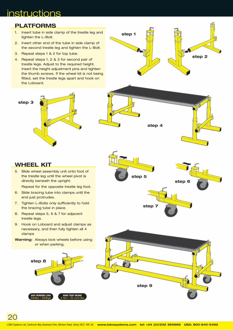
PLATFORMS1. Insert tube in side clamp of the trestle leg and
tighten the L-Bolt.
2. Insert other end of the tube in side clamp ofthe second trestle leg and tighten the L-Bolt.
3. Repeat steps 1 & 2 for top tube.
4. Repeat steps 1, 2 & 3 for second pair oftrestle legs. Adjust to the required height.Insert the height adjustment pins and tightenthe thumb screws. If the wheel kit is not beingfitted, set the trestle legs apart and hook onthe Loboard.
WHEEL KIT5. Slide wheel assembly unit onto foot of
the trestle leg until the wheel pivot isdirectly beneath the upright.
Repeat for the opposite trestle leg foot.
6. Slide bracing tube into clamps until theend just protrudes.
7. Tighten L-Bolts only sufficiently to holdthe bracing tube in place.
8. Repeat steps 5, 6 & 7 for adjacenttrestle legs.
9. Hook on Loboard and adjust clamps asnecessary, and then fully tighten all 4clamps
Warning: Always lock wheels before usingor when parking.
step 1
step 4
step 2
step 3
step 5
step 7
step 8
step 9
step 6
SAFE WORKING LOAD550lbs / 250kgs
HAND TIGHT MEANS5 Nm / 45 Inch-lbs
LOBO Systems Ltd, Centurion Way Business Park, Alfreton Road, Derby DE21 4AY, UK www.lobosystems.com tel: +44 (0)1332 365666 USA: 800-640-5492
instructions
20
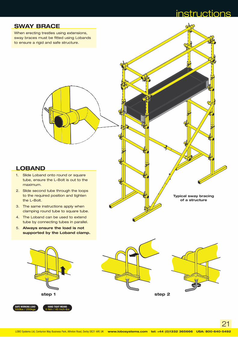
LOBAND1. Slide Loband onto round or square
tube, ensure the L-Bolt is out to themaximum.
2. Slide second tube through the loopsto the required position and tightenthe L-Bolt.
3. The same instructions apply whenclamping round tube to square tube.
4. The Loband can be used to extendtube by connecting tubes in parallel.
5. Always ensure the load is notsupported by the Loband clamp.
SWAY BRACEWhen erecting trestles using extensions,sway braces must be fitted using Lobandsto ensure a rigid and safe structure.
Typical sway bracingof a structure
SAFE WORKING LOAD550lbs / 250kgs
HAND TIGHT MEANS5 Nm / 45 Inch-lbs
2 pets1 pets
LOBO Systems Ltd, Centurion Way Business Park, Alfreton Road, Derby DE21 4AY, UK www.lobosystems.com tel: +44 (0)1332 365666 USA: 800-640-5492
instructions
21

TOWER & EXTENSIONS
step 1
step 2
step 3
step 4
SAFE WORKING LOAD550lbs / 250kgs
HAND TIGHT MEANS5 Nm / 45 Inch-lbs
LOBO Systems Ltd, Centurion Way Business Park, Alfreton Road, Derby DE21 4AY, UK www.lobosystems.com tel: +44 (0)1332 365666 USA: 800-640-5492
instructions
22
1. Construct two base trestle systems with the trestle legs and cross tubes.
Remove the telescopic inserts. Always ensure the side clamps on the legs are tight and face the same direction.
2. Fit the Loboard to the first lift point of the trestle systems and lock down with a Loband and piece of tube. Add the adjustable extensions and set at the required height, using the height adjustment pin. Add sway braces to the structure and more cross tubes.
3. Fit the handrail tubes and use a Loboard to provide the next stage to work from. Four outriggers can now be fitted using Loband clamps. Fit the ladders and secure with ladder clamps internally for accessing the middle and top Loboards.
4. Add additional extensions, handrail tubes and ladders as previously to a maximum standing height of 4.5m or 15ft, for this configuration. You should always ensure your safety by adding handrails at each step. Toe boards should be fitted.
Never exceed a height to base ratio of 3 to 1. Use additional sway braces on all sides as shown. At the top of each leg refit the telescopic inserts and fix to their maximum height to create the handrail supports. Fit handrail tubes using Lobands on all open sides to ensure maximum safety.
Sway braces can be fitted for extra stability. Always ensure all L Bolts and thumb screws are fully tight to produce a safe and secure structure before use. For safety, use tubing and Lobands to form handrails at any level during construction.

HANDRAILSHandrail posts are fitted to platform tubes
1. Fit the handrail posts to the platform support tubes. Ensure the locating plate on the bottom clamp slides into thetrestle leg top clamp. It must fit directly underneath the top clamp top plate, and above the clamp floating plate.
2. Ensure the locating plate is fully inserted.
3. Ensure the Handrail is vertical and then fully tighten the Handrail L-Bolt.
4. Insert tubing, of the appropriate length, into both the top and bottom side clamps, to form side handrails, spanningall handrail posts. Tighten the L-Bolts.
5. Attention: All four sides must be fitted for safe use as shown in Fig A.
Handrail Corner Posts
1. Slide the Handrail Corner Post onto the platform support tube. Ensure the locating plate slides into the trestle legtop clamp. It must fit directly underneath the top clamp top plate. Ensure the locating plate is fully inserted.
2. Ensure the Handrail Corner Post is vertical and then fully tighten the L-Bolt.
3. Repeat steps 1 and 2 for the three other corner posts.
4. Slide tubes of the appropriate length, into the corner post side clamps so that the ends protrude and tighten boththe side clamp, top and bottom L-Bolts.
5. Repeat step 4 for the three other sides.
6. Attention: All four sides must be fitted for safe use as shown in Fig A.
Handrails Using Trestle Leg Inserts
1. Extend the telescopic leg inserts to a height of 1m or 42 Inches.
Insert the height adjustment pin and tighten the thumb screw.
2. Slide tubing to form handrails into the top clamps and tighten the L-Bolts.
3. Position a second tube, of the same length, 0.47m or 18.5 inches up the telescopic inserts, to form the lowerhandrail, and lock into place using Lobands.
4. Use more tubing and Lobands to form the other sides of the handrail.
5. Attention: All four sides must be fitted for safe use as shown in Fig A.
Corner postSide handrail
postHandrail insert
post fitted into aleg top
HAND TIGHT MEANS5 Nm / 45 Inch-lbs
LOBO Systems Ltd, Centurion Way Business Park, Alfreton Road, Derby DE21 4AY, UK www.lobosystems.com tel: +44 (0)1332 365666 USA: 800-640-5492
instructions
23
NOTE: Always fit toeboards to handrail verticals.

TOE BOARDS & TOE BOARD ADAPTORA four sided toe board is located onto the Loboard using the locatinglugs on the corner hinges to ensure it is fitted correctly.
A single piece toe board can be positioned anywhere, and held inplace using toe board clips on handrail posts or toe board adaptor.
Single toeboard
Fig A Fig B
HANDRAILSSingle Handrails Using Swaybraces
A Handrail must be locked into place using an Adjustable Sway brace and 2 Lobands to comply with regulations asshown in Fig B.
HAND TIGHT MEANS5 Nm / 45 Inch-lbs
LOBO Systems Ltd, Centurion Way Business Park, Alfreton Road, Derby DE21 4AY, UK www.lobosystems.com tel: +44 (0)1332 365666 USA: 800-640-5492
instructions
24

LOBO Systems Ltd, Centurion Way Business Park, Alfreton Road, Derby DE21 4AY, UK www.lobosystems.com tel: +44 (0)1332 365666 USA: 800-640-5492
instructions
25
OUTRIGGERS
GATE
1. Position the outrigger in line with the trestle leg and then clamp the cross brace to the leg (point A) using aLoband.
2. Lift the outrigger and using the Loband, clamp at point B.
3. Remove the locating pin at the bottom of the outrigger and extend the outrigger insert to the ground.Secure in this position with the locating pin.
4. Loosen the Loband at point B and adjust the outrigger down unitl the outrigger cross brace is at 90° to thesupport leg.
5. Fully tighten both Lobands and the thumb screw.
point B
Always extend to maximum
0.9m36”
point B
point A
SAFE WORKING LOAD550lbs / 250kgs
HAND TIGHT MEANS5 Nm / 45 Inch-lbs
1. Three Lobands are required to fit a LOBO Gate, two for the Gate hinges and one for the side stop.
2. Position the LOBO Gate exactly vertical and attach to the Adjustable Extension, Extension or Handrail Insert.
3. Ensure the LOBO Gate is the correct way up and the side stop is fitted to stop the gate opening outwards from the LOBO System.

SAFE WORKING LOAD550lbs / 250kgs
Outriggers can be fitted to improve stability
Lifting Slider Frame
LIFTING SLIDER FRAME1. Slide the ends of the lifting beam into the top
clamps and fully tighten.
2. Extend the telescopic leg inserts on the trestlelegs to the desired height, insert heightadjustment pins and tighten the thumb screws.
3. Fit the ends of the sway braces into the clampson the top of the beam.
4. Swing the bottom ends of the sway braces outand using Lobands, clamp them to the trestlelegs.
5. Check that the clamps in use are fully tightened.
6. Outriggers can be used to add extra stability,if necessary.
Lifting sliderframe
LOBO Systems Ltd, Centurion Way Business Park, Alfreton Road, Derby DE21 4AY, UK www.lobosystems.com tel: +44 (0)1332 365666 USA: 800-640-5492
instructions
26
Outriggers can be fitted to improve stability

LIFTING SLIDER BEAM INTEGRATION1. Max Loading
Ensure that the proposed load to be lifted does not exceed the weight rating on the Lifting Slider Beam.Ensure you have checked that the proposed load does not exceed the cross tube rating. The cross tubing israted by its unsupported length as given by the steel tubing chart on page 15.
2 Load BearingEnsure you have the Lifting Slider Beam on top of a load bearing cross tube.
3 PositionEnsure the Lifting Slider Beam is central to the cross tubing to ensure the system is stable.
4 SecureEnsure you secure the Lifting Slider Beam at both ends using Lobands.
5 SwaybracesEnsure swaybraces are fitted correctly using Lobands.
6 ClampsEnsure all clamps and Lobands are fully tight.
SAFE WORKING LOAD550lbs / 250kgs
LOBO Systems Ltd, Centurion Way Business Park, Alfreton Road, Derby DE21 4AY, UK www.lobosystems.com tel: +44 (0)1332 365666 USA: 800-640-5492
27
instructions

The LOBO System Side ClampThe side clamp refers to any clamp located on the front face of any LOBOSystem component. Ensure that the L-Bolt is fully tightened during assembly.
Fig 1a: Shows the correct use of the LOBO System side clamp. You mustensure that the tube is level with the end of the side clamp orprotruding any distance required through the side clamp. You mustpay particular attention to ensure that the tube itself is level with theedge of the side clamp and not the end caps as this would mean thatthe tube itself is 5mm short of being flush with the edge.
Fig 1b: Clearly shows that the tube is not fully inserted into the side clampand this is not acceptable under any circumstances.
The LOBO System Top ClampThe top clamp refers to any clamp located on the top of the leg inserts ofany LOBO System component. Ensure that the L-Bolt is fully tightened duringassembly.
Fig 2a: Shows the correct use of the LOBO System top clamp. You mustensure that the tube is level with the end of the top clamp orprotruding any distance required through the top clamp. You mustpay particular attention to ensure that the tube itself is level with theedge of the top clamp and not the end cap as this would mean thatthe tube itself is 5mm short of being flush with the edge.
Fig 2b: Clearly shows that the tube is not fully inserted into the top clamp andthis is not acceptable under any circumstances.
The LOBO System LobandThe Loband is available with a round (LC1) or square (LC3) end. Theseinstructions apply to both varieties. Ensure that the L-Bolt is fully tightenedduring assembly.
Fig 3a: Shows the correct use of the LOBO System Loband clamp. You mustensure that the tube is protruding a minimum of 5mm through theLoband clamp and not just the end cap as this would mean that thetube itself would be flush with the edge of the Loband hoop anddamage may occur to the end cap causing the Loband to slip.
Fig 3b: Clearly shows that the tube is not fully inserted into the Loband clampand this is not acceptable under any circumstances.
The LOBO System Ladder ClampThe LOBO Ladder clamp must only be used to secure a ladder and has noother uses on the LOBO System. Ensure that the L-Bolt is fully tightenedduring assembly.
Fig 4a: Shows the correct use of the LOBO Ladder clamp. You must ensureat least 2 ladder clamps are used per ladder.
Fig 4b: Clearly shows no ladder clamps in use and this is not acceptableunder any circumstances.
Fig 4c: Clearly shows only one ladder clamp in use and this is not acceptableunder any circumstances.
HAND TIGHT MEANS5 Nm / 45 Inch-lbs
1a
1b
2a
2b
3a
3b
4a
4c
4b
LOBO Systems Ltd, Centurion Way Business Park, Alfreton Road, Derby DE21 4AY, UK www.lobosystems.com tel: +44 (0)1332 365666 USA: 800-640-5492
28
do’s & don’ts
Safety checks, periodic checks and maintenance
Whilst building the system ensure the following are checked:
L-Bolts/thumb screws on ALL system components are checked and are fully tight and are undamaged.
Check to ensure that all height adjustment pins are present and that the wire spring is present and undamaged.
Check ALL welds for signs of cracking. This check must also be carried out on the aluminium Loboards as well.
Check for dents in all system components including the round tubes and the aluminium Loboards.
Check the compression springs and their condition, the side clamp has 1 spring and the top clamp has 2 springs.
After 5 days of the system being erected:
Check to ensure that the L-Bolts/thumb screws are fully tight and are undamaged.
Check general condition of system and Loboards.
After 28 days of the system being erected:
Check L-Bolts/thumb screws on ALL system components are fully tight and are undamaged.
Check to ensure that all height adjustment pins are present and that the wire spring is present and undamaged.
Check ALL welds for signs of cracking. This check must also be carried out on the aluminium Loboards as well.
Check for dents in all system components including the round tubes and the aluminium Loboards.
Check for compression springs and their condition, the side clamp has 1 spring and the top clamp has 2 springs.
MaintenanceEvery 12 months:
Ensure that all L-Bolts and thumbscrews are greased to ensure maximum durability of the product.
If any damaged or missing parts are found, do not use theLOBO System until it is either repaired or replaced.
HAND TIGHT MEANS5 Nm / 45 Inch-lbs
LOBO Systems Ltd, Centurion Way Business Park, Alfreton Road, Derby DE21 4AY, UK www.lobosystems.com tel: +44 (0)1332 365666 USA: 800-640-5492
29
instructions

measurements are from the floor to the top of the board
TL1
TL2
Adjustable extensionbase plate
Adjustable extensionbase plate
Extensionbase plate
TL3
295mm - 115/8"
1105mm - 431/2"
1705mm - 67 1 /8"
2030mm - 797/8"
165mm - 61/2"
545mm - 217/16"
1145mm - 45"
1475mm - 583/16"
Extensiononly
795mm - 311/4"
1395mm - 547/8"
1720mm - 6711/16"
525mm - 203/4"
825mm - 321/2"
1355mm - 53"
525mm - 203/4"
1015mm - 40"
1350mm - 53"
2105mm - 83"
525mm - 203/4"
825mm - 321/2"
365mm - 143/4"
960mm - 373/4"
1295mm - 51"
295mm - 115/8"
165mm - 61/2"
295mm - 115/8"
LOBO Systems Ltd, Centurion Way Business Park, Alfreton Road, Derby DE21 4AY, UK www.lobosystems.com tel: +44 (0)1332 365666 USA: 800-640-5492
30
WC1
WC2
Wheels add 200mm - 8" to the height of a leg
useful dimensions
LOBO Systems Ltd, Centurion Way Business Park, Alfreton Road, Derby DE21 4AY, UK www.lobosystems.com tel: +44 (0)1332 365666 USA: 800-640-5492
31
1. GENERALThese Conditions of Trading shall apply in their entirety asbetween LOBO and the Customer and shall prevail overany inconsistent terms or conditions contained or referredto in the Customer’s order or in correspondence orelsewhere or implied by trade, Customer, practice orcourse of dealing unless specifically agreed to in writingby Lobo and any purported provisions to the contrary arehereby excluded.
These terms together with such special conditions as areagreed between the parties shall apply to all contractsmade or to be agreed by the Customer for the supply ofgoods.
LOBO reserves the right to amend or vary theseconditions of business on giving seven days noticethereof in writing.
No variation to the contract or these terms shall bebinding unless agreed in writing by the authorisedrepresentatives of the parties
2. ORDERSCustomers may order in response to LOBO’s writtenquotations, which shall be valid for 30 days.
An order constitutes an offer by the Customer topurchase the goods subject to these terms. Each orderconstitutes the basis of a separate contract.
No order shall be acted upon unless given by theCustomer in writing together with the Customer’s officialorder number.
3. PRICES3.1 The price of the goods shall be as set out in LOBO’s
written quotation provided prior to placement of order.Prices and all other sums payable hereunder shall beexclusive of Value Added Tax and all taxes or duties thatmay be levied or based upon the prices. Value Added Taxand all such taxes or duties (with the exception of any taxlevied or based upon the income of LOBO) shall be paidby the Customer as additional charges hereunder.
3.2 Each written quotation shall contain details of anyadditional charges including carriage and insurance.
4. SPECIAL REQUIREMENTSWe reserve the right to deliver and invoice any goodsmade especially to customer’s specification by us in goodfaith, and left on hand due to cancellation of all or part ofthe contract.
4.1 CancellationLOBO may at it’s absolute discretion, agree or not to theCustomer cancelling a purchase order with Lobo, subjectto a charge of up to 25% of the full amount of thecontract.
4.2 Modifications to an order can only be accepted subject tosuch charges (if any) as LOBO may in it’s absolutediscretion agree.
4.3 ReturnsLOBO may, at it’s absolute discretion, agree or not to theCustomer returning goods which have been purchasedfrom LOBO and are now surplus to the Customer’srequirements, subject to a Restocking charge of up to25% of the full amount of the goods returned.
The goods must be in the same condition as whendispatched to the Customer. Goods purchasedspecifically on a ‘Sale or Return’ or ‘Demonstration’ basiswill not be subject to a Restocking Charge.
5. PAYMENT5.1 LOBO requires cash or credit card details with orders
unless the Customer has an account with LOBO.
5.2 For Customers with accounts LOBO shall on or afterdelivery of the goods invoice the Customer for goodssupplied and each invoice shall give details of the goodsin question and quote the purchase order number.
5.3 Account Customers shall pay for goods delivered within30 days from the date of invoice. LOBO reserves the rightto withdraw an Account Customer’s credit facility at anytime.
5.4 The Customer agrees to make known in writing to LOBOany comments, complaints or other lawful objectionswhich may delay the payment of the invoice by the duedate.
5.5 LOBO may exercise it’s statutory right to charge theCustomer interest at the rate of 8% per annum above thethen current base rate and also compensation for debtrecovery costs under the late payment legislation for nonpayment or any payments which are not in accordancewith our agreed terms.
6. DELIVERY6.1 Unless otherwise agreed in writing, LOBO shall deliver the
goods to the delivery location specified by the Customerin the order.
6.2 Delivery shall be subject always to availability. WhereLOBO has the requisite goods in stock, dispatch followingan order will normally be within 3 working days unlessotherwise arranged.
6.3 All cancelled orders are subject to a restocking charge.
6.4 For any order in excess of £15,000 LOBO reserves theright to divide the consignment into separate batchesnone of which shall be in excess of £15,000.
7. RISK AND PROPERTY7.1 Risk in the goods shall pass to the Customer when the
Customer has accepted delivery at its premises.7.2 The goods shall remain the property of LOBO until paid for
in full by the Customer.
8. ACCEPTANCE8.1 If any goods comprised in a delivery are damaged in
transit, are defective or not in accordance with the orderthe Customer may either reject that part or, at its option,require LOBO to replace the damaged goods free ofcharge as quickly as possible provided that in the case ofdamage to or defects in the goods.(a) apparent at delivery, the Customer shall so notifyLOBO within 24 hours of delivery and(b) not apparent at delivery, the Customer shall so notifyLOBO within 48 hours of delivery.
8.2 All costs relating to carriage and re-delivery of goodsrejected by the Customer shall be borne by LOBO.
9. WARRANTIES & LIABILITIES9.1 LOBO warrants to the Customer that for a period of 12
months, or such other period as may be notified inwriting, from the date of delivery, the goods shall be freefrom defects in design, materials and workmanship.
9.2 The Customer shall notify LOBO of any breach of thiswarranty and LOBO shall promptly, at its option, eitherrepair or replace the defective Goods (or relevant part).Any delivery expenses relating to (i) the return to LOBO’spremises of the defective Goods (or part); and (ii) thedelivery of replacement or repaired goods (or parts) shallbe borne by LOBO.
9.3 LiabilityLOBO fully excludes all liability whatsoever to theCustomer in any way relating to this contract, gives noexpress warranties, other than those referred to inparagraph 9.1 above and expressly excludes theoperation of any implied warranties and the Customershall indemnify and hold LOBO harmless against anyliability whatsoever.
10. IPR INDEMNITYLOBO warrants that the goods shall not infringe any patenttrademark or other intellectual property right of any thirdparty and shall, at its own expense, indemnify and holdharmless the Customer and defend any action broughtagainst same with respect to any and all liabilities,actions, claims, proceedings, damages, reasonable costs(including but not limited to court costs and reasonablelegal fees), charges and demands, to the extent such arebased upon a breach of this warranty.
11. CONFIDENTIAL INFORMATIONUnless otherwise specifically agreed by LOBO, no detail,or information of any kind, is to be disclosed to any thirdparty and all matters relating to the Contract are to beconsidered confidential. Nothing relating to the Contractis to be used by the Customer other than for thepurposes of performing the Contract.
12. FORCE MAJEUREEither party shall be excused from the performance of itsobligations under a contract if and to the extent that suchperformance is prevented by reason of any act or matterbeyond the reasonable control of the party claiming thebenefit of this clause.
13 LAW AND ARBITRATIONThe contract shall be governed by and construed inaccordance with the laws of England and the partiesagree to submit to the jurisdiction of the English courts.
GENERAL CONDITIONS FOR SUPPLY OF GOODSLOBO Systems (“LOBO”) and The Customer (“Customer”)
terms & conditions

www.lobosystems.com
LOBO Systems LtdCenturion Way Business ParkAlfreton RoadDerby DE21 4AY, UK Tel: +44 (0)1332 365666Fax: +44 (0)1332 365661
BS 1139 parts 3 & 4BS EN1004:2004