local planning policy 5
TRANSCRIPT

Page 1
LOCAL PLANNING POLICY 5.22
T I T L E : SHIRE OF BROOME STRUCTURE PLAN AND SUBDIVISION STANDARDS
A D O P T E D : OMC 26 November 2015 – Page 27
R E V I E W E D : OMC 25 May 2017 – Pages 85 – 260
OMC 14 December 2017 – Pages 1030 – 1043
OMC 26 April 2018 – Pages 17 – 57
OMC 12 December 2019 – Pages 213 - 221
A S S O C I A T E D L E G I S L A T I O N :
Planning and Development Act 2005 Planning and Development (Local Planning Schemes) Regulations 2015
Local Planning Scheme No. 6
A S S O C I A T E D D O C U M E N T S :
Liveable Neighbourhoods 2015
Structure Plan Framework 2015
Relevant State Planning Policies
R E V I E W R E S P O N S I B I L I T Y :
Director Development Services
Director of Engineering Services
D E L E G A T I O N : N/A
A P P L I C A T I O N : This policy applies to all land within the Shire of Broome.
Previous Policy Number 8.32 O b j e c t i v e :
• Establish a clear framework for the preparation and assessment of Structure Plans and applications for subdivision within the Shire of Broome and to outline variations to state planning documents specific to local Broome conditions.
• Facilitate subdivision and development that meets the needs and expectations of the Broome community.
• Recognise that a wide range of different design elements/planning considerations need to be considered in the preparation and assessment of Structure Plans and applications for subdivision.
• Assist with the implementation of the Shire’s Local Planning Strategy and the achievement of the objectives set out in the Shire’s Local Planning Scheme.
• Outlines when the Shire of Broome will support a Structure Plan or subdivision that proposes the application of the regional variation included in Liveable Neighbourhoods, to allow the public open space contribution being reduced to a minimum of five percent of the gross subdivisible.

Page 2
D e f i n i t i o n s : Development plan means a Structure Plan progressed and adopted in accordance with clause 4.25 of the Shire of Broome Town Planning Scheme No. 4. Structure plan means a plan adopted under the Deemed Provisions, which indicates broad land use options for the subdivision and development of an area and provides a policy framework for such future subdivision and development. Acronyms LWMS Local Water Management Strategy LPP Local Planning Policy TPS4 Town Planning Scheme No. 4 LPS6 Local Planning Scheme No. 6 POS Public Open Space BUWM Better Urban Water Management UWMP Urban Water Management Plan WAPC Western Australian Planning Commission Shire Shire of Broome CPTED Crime Prevention Through Environmental Design LN Liveable Neighbourhoods P o l i c y : Format of the Policy The Policy is established in six parts, as follows:
• Section 1 – Application, General Provisions and Format of the Policy
• Section 2 – Liveable Neighbourhoods - Variations and Additions Application: Structure Plans and Subdivision Applications This section of the Policy will set out variations to Liveable Neighbourhoods or will establish additional planning matters to be addressed to ensure that subdivision and development is planned and designed to meet local conditions. The section is structured consistent with the elements and headings under Liveable Neighbourhoods.
In some elements, where required to provide background and context, explanatory text will be provided within a text box as presented here. This does not form provisions of the Policy, however provides an explanation and a context for the policy provisions.
• Section 3 – Shire of Broome Addendum to IPWEA Guidelines to Subdivisional
Development Application: Subdivision Applications This section of the Policy will set out variations to the IPWEA Local Government Guidelines for Subdivisional Development (IPWEA Guidelines) and provides guidance on the following:

Page 3
• establish minimum requirements for the design of civil works required to satisfy conditions of subdivision approvals.
• requirements for supervision of subdivision works, document specifications and actions required to be satisfied by the proponent prior to lodgement of subdivision clearance.
• Section 4 - Guidelines for the Design of Stormwater Drainage Systems
Application: Subdivision Applications This section establishes guidelines for the design of stormwater drainage systems to address local conditions experienced in Broome.
• Section 5 - Guidelines and Specifications for Reticulation Systems and Associated Works in Public Open Space Areas
Application: Subdivision Applications This section will establish guidelines and specifications for reticulation systems and associated works in public open space areas. Section 1.0 – Application & General Provisions
Application 1.1 This Policy applies to the following forms of residential/urban structure planning
and subdivisions:
• New Structure Plans that have not yet been endorsed by the Shire of Broome. • New subdivision applications for greenfield sites or sites zoned ‘Urban
Development’ that have not yet been determined by the Western Australian Planning Commission.
• Proposed amendments to existing Structure Plans. • Detailed designs for engineering drawings, landscape drawing approval and
similar where subdivisions are already the subject of approval but where a deposited plan for the specific lots have not yet been lodged with the Western Australian Planning Commission.
• Future stages of subdivision within residential estates, even in instances where some initial stages of subdivision have been completed.
General 1.2 Structure Plans are to be prepared consistent with the format within the WAPC
Structure Plan Framework (2015) except where varied in the policy. 1.3 The following information is required to be depicted on the Structure Plan Map
(in addition to, or supplementary to the content listed in Table 1 of the WAPC Structure Plan Framework) or is to be provided on the non-statutory structure plan map under Part 2:
(i) The location and orientation of all streets, including local access streets;
and (ii) The location of all POS areas.

Page 4
1.4 In addition to the matters required to be addressed through the WAPC Structure
Plan Framework, Part 2 of the Structure Plan shall include the following:
(i) An indicative subdivision layout showing the road network, proposed lot orientation, public open space, land use/density and other relevant information consistent with Part 1 Structure Plan Map and associated statutory provisions.
1.5 The design/planning elements must be consistent with the State Planning
Framework, including Liveable Neighbourhoods, except where varied in this policy.
1.6 This policy will establish any variations to the requirements of Liveable Neighbourhoods and will also establish any additional elements not specified that are to be addressed. 1.7 Where it is not practical for the minimum standards to be met, these matters should be discussed with the Shire prior to submission and written justification should be provided at the time of application including:
i. the details of the areas of non-compliance; ii. an explanation of the reasons for non-compliance; and iii. whether any other measures have been established to ensure that the
established objectives will continue to be satisfied. Section 2.0 – Liveable Neighbourhoods - Variations and Additions
Element 1 – Community Design
For thousands of years, there have been diverse cultural interactions and connections with the Broome area, including Roebuck Bay and surrounding areas. These days, the Broome area is often referred to as a ‘cultural melting pot’, with people from different cultural backgrounds either living or visiting the area. At the core of Broome’s culture is the community’s connection with the outdoors. In particular, the Broome community greatly values its connections with the sea and climate. Further there are strong associations with the bushland and broader landscape and environment. It is this aspect of Broome which has come to define the local culture and character of the area. In the preparation of Structure Plans and applications for subdivision, planning for new subdivision and developments, the layout should enhance local identity by responding to the site context, site characteristics, setting, landmarks and views and incorporate key elements of natural and cultural significance. Fundamentally, it is important to first understand the matters of cultural significance and then respond appropriately through suitable design response.
Site Context and Analysis
2.1 If the proposed site exhibits the following characteristics:
• The site is known to have any priority flora, fauna and habitat; • The site is positioned within the P1 drinking water source area;

Page 5
• The site is known to be impacted by flooding, inundation or storm surge from the ocean, ephemeral creeks and floodplains;
• Preliminary site investigations indicates the presence of acid sulphate soils; or
• Desktop analysis of historical land uses to identify any potential contaminated sites;
then an environmental assessment and management strategy is to be
prepared and attached as a technical appendices to the Structure Plan. 2.2 Within Part 1 of a Structure Plan, under the section 7 ‘other requirements’
include a table identifying relevant outstanding studies, investigations and information and the stage when it will be approved/implemented, this may include the following:
• Weed and pest management plan; • Foreshore / environmental / bushland / tree / wetland / wildlife protection
management plan. 2.3 The design and layout of the Structure Plan/subdivision should respond to the
elements identified the contexts and constraints plan. A description should be provided under Part 2 of the Structure Plan setting out how the design addresses the site context and constraints identified.
Urban Water Management
In Broome, urban water management is a primary consideration due to the extreme wet season conditions and therefore it is critical that water management is addressed early in the Structure Plan/urban design process for any area. The Urban Water Management network is generally the form giving element to new urban areas from which the rest of the layout and design elements should be applied. Urban water management responses in Broome differ significantly from measures implemented in the south west of WA. Key factors which require a different approach in Broome are:
• Climate – high volume and intense rainfall events over a concentrated wet season; • Soils – Pindan soil have low permeability rates, limiting the ability for infiltration of stormwater
at source; • Prevalence of Mosquito’s – given the potential human health impacts drainage systems must
be designed to avoid breeding sites being created. • The low grades of land and high risk of scarring and sedimentation from stormwater discharge.
As such the following practices are implemented in Broome:
• Roads are used to convey stormwater to swale systems; • New lots must be graded to the road and designed so that stormwater is not retained but
disposed onto the street. • Use of onsite infiltration measures and rainwater tanks are ineffective. • Natural drainage channels/depressions should be utilised in stormwater design. • Management of erosion through the re-mulching of vegetation is required to stabilise swales
and lots.

Page 6
• Daylighting of stormwater at outlet points is required to minimise scour of downstream environs.
2.4 Local Water Management Strategies (LWMS) shall be prepared at the first stage
of the Structure Plan process to ensure that the stormwater system is appropriately sized to accommodate future stormwater movements and should follow natural drainage channels/depressions.
2.5 Prior to the submission of a Structure Plan, the LWMS should be submitted to the
Shire and Department of Water for initial comment. Details of pre-submission consultation should be outlined In Table 4 – pre-lodgement consultation of the Structure Plan.
2.6 In addition to the above, all LWMS are to address the following:
a) Any preliminary designs of downstream stormwater discharge points must be provided and developer must acknowledge that it is their responsibility to secure access and fund any downstream works.
b) Preliminary geo-tech findings and acid sulphate testing must be detailed; c) Models for off-site impacts required to prevent flooding; and d) Ongoing management measures to be implemented by the developer
during the two year maintenance period, including street sweeping, silt removal and weed management.
Element 2 – Movement Network
With respect to the movement network, below are some key characteristics influencing expectations with regard to design of new urban areas: • Broome does not have a public transport service. This may change in the future therefore all
new urban areas should be designed to accommodate public transport. • Climate is a significant factor impacting upon the ability of people to walk or cycle, particularly
in the wet season. Shading of these networks is important. • Historical subdivisions in Broome are characterised by wide road reserves and road
pavements. While this has been modified over time road reserves and pavements generally are greater than that provided in Liveable Neighbourhoods.
• There are significant seasonal variations in the amount of traffic on the road network, with large numbers of visitors/boats and caravans during the tourist seasons.
• Due to the large proportion of shared housing arrangements, there are often more than two cars for each dwelling.
• The Broome Port is planning for further growth and with this there will be an increase in heavy vehicle movements.
• Many local people make reference to the ‘7 minute commute’, being an expectation of generally being able to get from any location in town to any other location in 7 minutes.
Pedestrian Requirements 2.7 Requirement 1.6, first and second dot-point is amended such that all footpaths
(unless the footpath is within 400m of an activity centre) must be a minimum of 2m wide; offset a minimum of 0.3m from property boundaries.
Street Network Requirements

Page 7
Broome existing urban areas are characterised by wide road reserve and road pavements which contribute significantly to the established character. The wide road reserves facilitate breeze movements, allow for establishment of landscaping, informal parking of vehicles on the verge and contribute to the lower density character. The road pavement width is critical to allow for adequate area for the parking of vehicles on the road pavement without obstructing vehicle movements and to accommodate future bus movements through urban areas.
2.8 Requirement 1.13 requires that all streets are designed in accordance with
required function, design, design characteristics and traffic volumes in Table 3 and Table 4. The Shire of Broome adopts the following variations to Table 3 and Table 4 and subsequent changes to cross-sections:
i) Access Street C, indicative street reserve width is a minimum of 18m and
minimum street pavement width is 7.4m; ii) Access Street D, indicative street reserve width is a minimum of 18m and
minimum street pavement width is 6m; iii) Any street requiring on street parking is to be a minimum width of 2.5m.
Element 4 – Lot Design
Because of Broome's climate, the priorities when designing urban layouts are to minimise solar radiation (except for some morning sun in the winter months) and capture air movement. Openness and shading should be the dominant characteristics for building design and this should also inform design of new urban areas. There are significant investigations undertaken in to how to build appropriately for Broome’s climate. Important further reading includes:
• Broome North’s Housing Guide (prepared by CODA on behalf of LandCorp and Shire of Broome 2009);
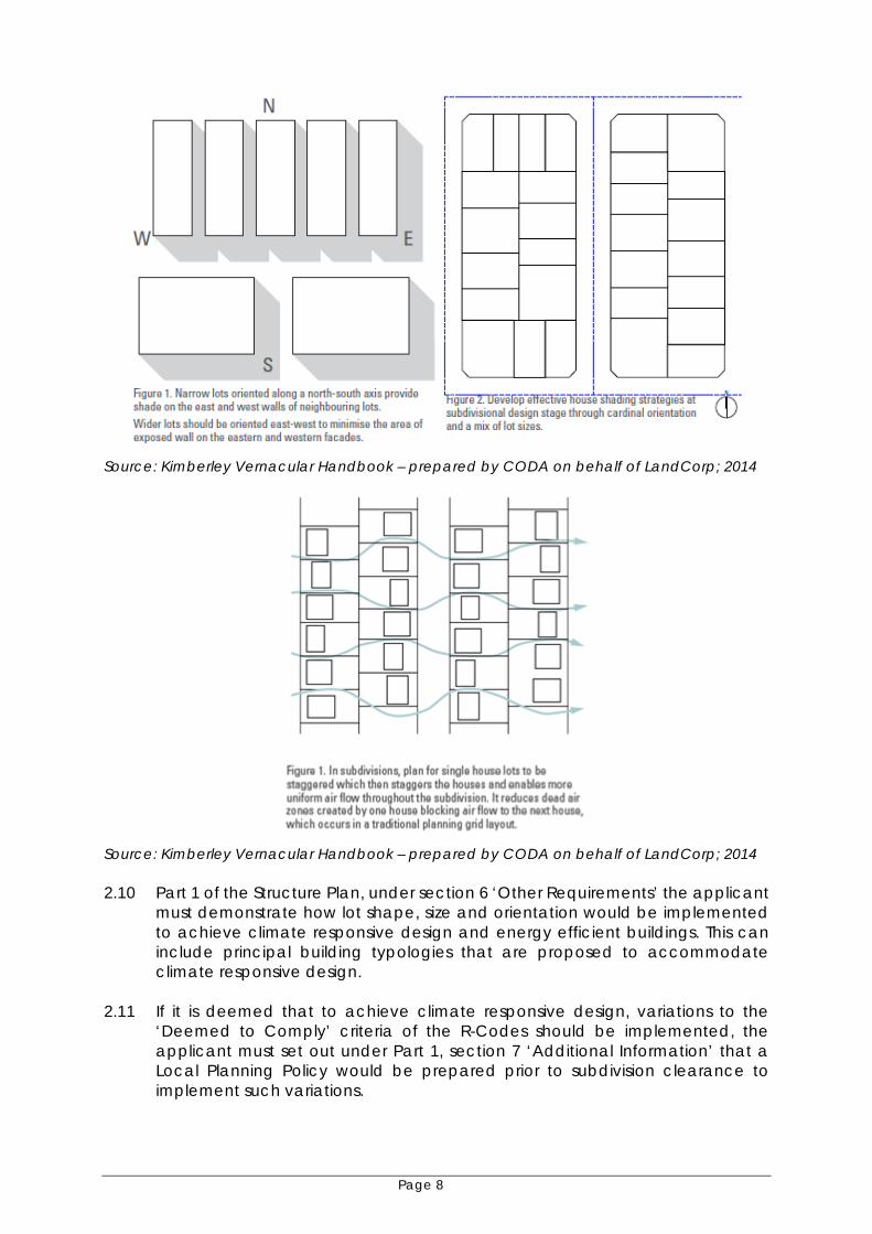
• The Kimberley Vernacular Handbook (prepared by CODA on behalf of LandCorp July 2014). Site Responsive Design Requirements 2.9 Requirement 5.3 – Amended as follows: The street and lot layout is to be consistent with the following principles:
(i) All urban areas should be designed with a grid pattern distribution of streets with street bocks orientated so the longest length is north-south orientated;
(ii) Lots on the north/south orientation should be narrow to reduce the potential for solar gain;
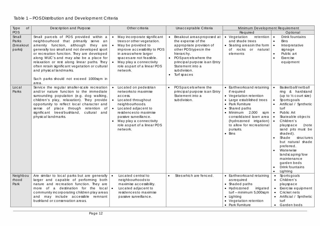
(iii) Staggered blocks are preferable to enhance airflow. The below figures show design elements that should be incorporated into subdivisions to achieve energy efficiency.
Page 8
Source: Kimberley Vernacular Handbook – prepared by CODA on behalf of LandCorp; 2014
Source: Kimberley Vernacular Handbook – prepared by CODA on behalf of LandCorp; 2014 2.10 Part 1 of the Structure Plan, under section 6 ‘Other Requirements’ the applicant
must demonstrate how lot shape, size and orientation would be implemented to achieve climate responsive design and energy efficient buildings. This can include principal building typologies that are proposed to accommodate climate responsive design.
2.11 If it is deemed that to achieve climate responsive design, variations to the
‘Deemed to Comply’ criteria of the R-Codes should be implemented, the applicant must set out under Part 1, section 7 ‘Additional Information’ that a Local Planning Policy would be prepared prior to subdivision clearance to implement such variations.

Page 9
Element 5 – Public Open Space
Appropriately sized, located and designed open space areas are instrumental in delivering a number of community benefits related to:
• Population health; • Environment; • Community development; • Community education; • Sense of place; and • Respecting cultural significance.
POS areas also have a role to play in urban water management. The provision of POS presents a number of challenges for the Shire and the community due to the on-going management and the associated financial implications. These need to be considered in the context of ensuring usability into the future and not compromising cultural values. The provisions below set out a different approach to that provided in Liveable Neighbourhoods. Liveable Neighbourhoods promotes higher distribution of smaller ‘local parks’ which overlap in catchments with larger neighbourhood parks. The Shire of Broome seeks that larger POS sites are provided interconnected by linear multiple use open space corridors. Further, it is proposed that the regional variation provided for in Liveable Neighbourhoods in regard to the amount of the POS contribution is adopted. This would see the amount of land required for a POS contribution being reduced from 10% to 5% of the total gross subdivisible area. This together with the provisions in relation to distribution and size of POS areas would allow for adequate distribution of POS, maintenance of residential amenity and balance maintenance costs. The policy seeks that in lieu of the additional 5% of land area that would ordinarily need to be given up as POS, a 2% cash-in-lieu contribution is made. These funds, in accordance with Appendix 4 of Liveable Neighbourhoods, would be utilised for the improvement or development of lands for parks and recreation purposes to ensure that residential amenity and district level facilities are provided for.
Public Open Space Function and Size Requirements 2.12 To assess whether the proposed POS function and size is appropriate a POS/landscaping management plan is to be submitted as a technical appendix to a Structure Plan and must address the following:
• A landscaping concept plan for all small, local, neighbourhood and district parks demonstrating whether the park is designed to be sport, recreation, nature, community or linear spaces;
• Key design principles and themes; • Connectivity to existing open spaces areas and reserves; • Areas of vegetation to be retained; and • Street trees.
Public Open Space Provision Requirements 2.13 As provided for under the regional variation R9.4, the public open space
contribution set out in R9.1 is varied to require:

Page 10
Unless district open space is required to be provided within the Structure Plan
area, a minimum contribution of five percent of the gross subdivisible area is to be given up free of cost for public open space by the subdivider providing the following are met:
i. A 2% cash-in-lieu contribution is paid to the Shire which is to be used by
the Shire for improvements or development of public open space reserves within the Broome townsite;
ii. No portion of the five percent of public open space can include restrictive use public open space or spaces used for water management purposes;
iii. Adequate areas are provided elsewhere for drainage, flooding, particularly overland flow and such areas are to be developed consistent with the Multiple Use Corridor (MUC) landscaping typology as set out in Clause 2.14 (note, MUC areas will not be credited as Public Open Space however will form a deduction from the gross subdivisible area);
iv. The public open space is developed to a minimum standard including full earthworks, basic reticulation, grassing of key areas, pathways that form part of the overall pedestrian and/or cycle network and maintenance for two summers in accordance with a landscaping plan approved by the Shire;
v. The size of public open spaces and distribution criteria in Table 1 of this Policy must be satisfied.
2.14 Any MUC to be developed shall meet the following:
• Provide a linear green network and pedestrian connections to the wider POS areas;
• Be adequate in size to accommodate required area for stormwater management and treatment;
• Must be designed such that they do not form a barrier between urban areas with connection points being provided across corridors;
• Swales must have batters no steeper than 1:6 (exceptions will be considered where swales are narrowed to provide a pedestrian crossing point or protection of significant trees) and must be revegetated to improve stormwater quality;
• Have low maintenance break-out areas or small parks (not turfed) designed as a nature/recreation function with low maintenance nature play (as set out in Table 1 of this Policy). (note: only the area of the small park can be credited toward POS contribution and the remaining land area will be a deduction from the gross subdivisible area).
Indicative concept design for MUC Source: Local Development Plan 3 Broome North

Page 11
Indicative cross-section for MUC Source: Local Development Plan 3 Broome North
2.15 Additional Requirement – the following criteria and direction should be
referenced when preparing a Structure Plan and POS/landscaping management plan:
Page 12
Table 1 – POS Distribution and Development Criteria
Type of POS
Description and Purpose Other criteria Unacceptable Criteria Minimum Development Requirement Required Optional
Small Parks (breakout parks)
Small parcels of POS provided within a neighbourhood that primarily serve an amenity function, although they are generally too small and not developed sport or recreation function. They are developed along MUC’s and may also be a place for relaxation or rest along linear paths. They often retain significant vegetation or cultural and physical landmarks. Such parks should not exceed 1000sqm in area.
• May incorporate significant trees or other vegetation.
• May be provided to improve accessibility to POS in areas where larger spaces are not feasible.
• May play a connectivity role as part of a linear POS network.
• Breakout areas proposed at the expense of the appropriate provision of other POS types in the hierarchy.
• POS parcels where the principal purpose is an Entry Statement into a subdivision.
• Turf spaces
• Vegetation retention and shade trees
• Seating areas in the form of rocks or natural elements
• Drink fountains • Bins • Interpretative
signage • Public art • Exercise
equipment
Local Parks
Service the regular smaller-scale recreation and/or nature function to the immediate surrounding population (e.g. dog walking, children’s play, relaxation). They provide opportunity to reflect local character and sense of place through retention of significant trees/bushland, cultural and physical landmarks.
• Located on pedestrian networks to maximise access.
• Located throughout neighbourhoods.
• Located adjacent to residences to maximise passive surveillance.
• May play a connectivity role as part of a linear POS network.
• POS parcels where the principal purpose is an Entry Statement into a subdivision.
• Earthworks and retaining if required
• Vegetation retention • Large established trees • Park Furniture • Shared paths • Minimum 2,000 sqm
consolidated lawn area (hydrozoned irrigation) to allow for recreational pursuits.
• Bins
• Basketball/netball ring & hardstand (up to ½ court size)
• Sports goals • Artificial / Synthetic
turf • Public Art • Skateable objects • Children’s
playspace (note sand pits must be shaded).
• Shade structures but natural shade preferred.
• Waterwise landscaping/low maintenance garden beds
• Drink fountains • Lighting
Neighbourhood Park
Are similar to local parks but are generally larger and capable of performing both nature and recreation function. They are more of a destination for the local community incorporating children play areas and may include accessible remnant bushland or conservation areas.
• Located central to neighbourhoods to maximise accessibility.
• Located adjacent to residences to maximise passive surveillance.
• Sites which are fenced. • Earthworks and retaining as required
• Shaded paths • Hydrozoned irrigated
turf – minimum 5,000sqm • Lighting • Vegetation retention • Park Furniture
• Sports goals • Children’s
playspace • Exercise equipment • Cricket nets • Artificial / Synthetic
turf • Garden beds

Page 13
• Drink fountains • Bins
• Basketball/netball ring & hardstand (up to ½ court size)
• Floodlighting • Skateable objects • Public Art • BBQs and
associated furniture • Toilets
District Park
Principally provide for a sport function, yet are large enough to accommodate a variety of concurrent uses including informal recreation, children’s play, picnicking, dog walking, social gatherings and individual activities. District open space may also serve a nature function. Often include higher order recreation infrastructure (clubrooms, floodlights, multipurpose courts, etc)
• May be co-located with schools to create district community hubs.
• Should be located close to major roads and other community facilities.
• Should be easily accessible by pedestrians, cyclists and motor vehicles.
• Spaces should be designed to minimise potential impacts of noise, traffic and light spill on residential areas.
Guided by Recreation Strategy.
Guided by Recreation Strategy
Linear Open Space
Open Space created to assist with connectivity, encourage pedestrian movement along park avenues and provide ecological corridors and opportunities for living steams. Can be aligned with an MUC, however to be credited as POS area forming the linear open space must not accommodate water management measures and the width of the linear open space must be a minimum of 15m.
• Designed in accordance with Designing out Crime Guidelines.
• Overlooked by residential lots for at least 50% of the length.
• Must not incorporate land used for water management purposes.
• Vegetation retention and shade trees
• Seating areas in the form of rocks or natural elements
• Drink fountains • Bins • Interpretative
signage • Public art • Exercise
equipment

Page 14
Development of Public Open Space Requirements 2.16 Where subdivision applications proposed the creation of open space, the Shire
shall in its response to the WAPC, request that a condition be imposed requiring the applicant to develop the open space to the minimum standard set out in Table 1 of this Policy. Note: District level POS must be ceded to the Crown free of cost, however it is not the applicant’s responsibility to develop this level of POS to the level identified in the Recreation Strategy, with the exception of any earthworks or turf establishment.
2.17 Development of POS above minimum standards may be acceptable subject to approval by the Shire. The future of infrastructure considered to ‘optional’ under Table 1 of this Policy is to be agreed prior to approval of landscaping plans. Whole-of-life cost estimates must be provided at the time of submitting landscaping plans to support provision of all infrastructure items.
2.18 Landscaping plans must be submitted for assessment at the same time as subdivisional working drawings.
2.19 No clearing of vegetation or other works shall occur within the area of open space until the Shire has granted approval for the subdivisional working drawings and associated landscaping plans.
2.20 Any areas of turf, other than for formal organised sports grounds, must have maximum grades of 1:20.
2.21 All grass reticulated areas are to be setback a minimum of 2m from the edge of any area of road pavement to prevent deterioration of road pavement and promote water conservation principles.
Section 3 – Broome Subdivision Standards
Background The Institute of Public Works Engineers Australia has established guidelines for subdivision development guidelines as a reference guide for developers, planners, engineers, technical consultants and contractors involved in subdivisional design and construction. The guidelines can be interpreted as setting out the minimum requirements that should be accepted by a local government in granting clearance of the engineering conditions imposed on a subdivision by the Western Australian Planning Commission (WAPC). The Commission is ultimately the subdivision approval authority in Western Australia, acting under the Planning and Development Act 2005. The following section will establish provisions which vary the IPWEA Local Government Guidelines for Subdivisional Development, 2012 (IPWEA Guidelines). These provisions will take precedence over the IPWEA Guidelines in all subdivision approvals. With regard to bonding of subdivision works, the Shire of Broome adopts the practices outlined in the IPWEA Guidelines, except where amended below.

Page 15
Application of the standards 4.1 The subdivision standards are intended to apply to all subdivisions within the Shire of Broome, regardless of whether or not there is a Structure Plan in place or in preparation. Module No 1 – Legal Framework and Contract Administration 4.2 Clause 1.17.4.1 Inspection for Roadworks is deleted and replaced with the
following clause:
An inspection with the contractor, consultant and the Shire will be required as a minimum for each of the following main stages of the construction of roadworks: • When the road has been boxed out and the subgrade shaped and
compacted to a tightly bound homogeneous surface with no cracking or delamination.
• When the basecourse has been placed, graded, compacted, water bound and trimmed to the correct shape, level, specifications and finish before sealing takes place. Surface levels to be audited by licensed surveyor with survey and compaction test results provided at the inspection by the Shire prior to seal application.
• After sweeping of the basecourse and prior to placement of sprayed surface or asphalt wearing course;
• After sealing and before application of kerbing, especially inspection of all kerb keys on all curve radii.
• Prior to construction of any footpaths. 4.3 Clause 1.18 Practical Completion the following is added:
If requested, the contractor shall arrange for the full sweeping of all roads to remove silt, debris and surplus sealing aggregate prior to the final inspection.
4.4 Defects Liability – Clause 1.21.1 General the following is added:
It shall be deemed to be the responsibility of the developer to repair any defects resulting faulty workmanship and/or defective materials on all drainage infrastructure for a period of 24 months from the date of practical completion – referred to as the defects liability period.
Module 2 – Site Preparation Guidelines 4.5 Clause 2.2.1.1 General paragraphs 3 & 4 are replaced with:
Where it is necessary to fill to the boundary of a subdivision, a suitable retaining wall shall be erected immediately inside the boundary of the subdivision. Alternatively if approved by the Shire of Broome the fill shall be carried beyond the boundary for a minimum distance of 1.0m and battered to a natural

Page 16
ground level at a slope no greater than 1:3. The written consent of the owner of the abutting land shall be obtained before proceeding with earthworks. All retaining walls proposed for construction in a subdivision shall be designed and certified by a practising structural engineer in accordance with the Building Code of Australia, R Codes and as approved by the Shire of Broome to accept all potential structural loading including construction loads. The retaining walls must also be certified post-construction by a practising structural engineer.
4.6 Clause 2.2.1.2 Residential Areas replace paragraph 1 & 2 with the following:
In all areas when subdivisional development is proposed and the Shire of Broome specifies re-contouring to take place, the gradient from back to front and across the lots boundary to boundary shall generally be from 0.5% to 1%. Any variations or exemptions to these gradients must be specifically agreed to and approved by the Shire of Broome.
4.7 Clause 2.2.1.3 Industrial Areas replace paragraphs 2 & 3 with:
In all areas when subdivisional development is proposed and the Shire of Broome specifies re-contouring to take place, the gradient from back to front and across the lots boundary to boundary shall generally be from 0.5% to 1%. Any variations or exemptions to these gradients must be specifically agreed to and approved by the Shire of Broome.
4.8 Clause 2.2.1.5.3 Soil stabilisation, dust and smoke control and Clause 2.2.1.5.4
Soil stabilisation strategy the following is added:
All lots and drainage areas should be stabilised as soon as practicable following disturbance. The following minimum standards are expected: • The batters of all drainage swales are to be stabilised through approved
landscaping and the immediate application of site mulch and topsoil; • All residential lots cleared are to be stabilised through the application of
a 3m wide mulch bund measured from the back of kerb line. All topsoil and vegetation for clearing must be collected from the development site prior to bulk earthworks. All vegetation is to be mulched and stored with the top soil for reapplication/reuse on site.
Module No 3 – Road Guidelines 4.9 Table 3.2 Road Classification the provisions of this table are modified consistent
with Clause 2.10 above. 4.10 Table 3.4 Summary of Planning Criteria for Residential Roads add in Note 12 to
be read in conjunction with Table 3.4
Note 12 Generally seal carriageway widths in residential areas in the Shire of Broome are 7.4m wide with a minimum of 6m allowed on some low

Page 17
trafficked streets. Variations to these seal widths may be approved in some cases and these will be assessed and approved on a case by case basis with relation to the proposed road layout.
4.11 Clause 3.3.2.1 – General replace paragraph 3 with: Generally longitudinal road design grades should be no less than 0.5%
minimum. However grades down to 0.35% may be accepted in difficult circumstances.
4.12 Clause 3.3.4 Verge and Property Grades replace paragraph 1 with:
Verge grading shall be 2% from the top of kerb to the property boundary, any lot level to verge level transitions to this grade must occur within the property itself and be graded up to surface at a maximum of 1:6.
4.13 Clause 3.3.4 Verge and Property Grades -
(i) add the following to paragraph 2: The minimum kerb radius on all industrial intersections shall be 15m.
(ii) Replace IPWEA Table 3.6 with:
Generally all kerbing for subdivisions in Broome shall be as follows: Flush Kerbing • Adjacent to public open space, trafficable median islands, median swales
and non-active areas to achieve Water Sensitive Urban Design outcomes. • The edges of through carriageway abutting eyebrow treatments and to
form an edge for brick paved thresholds etc. • May be approved for minor access streets and laneways.
Mountable Kerbing • Outer rings of roundabouts (note: needs to be fully trenched into the
pavement 100mm deep). • Other locations specifically approved by the Shire of Broome. Semi-Mountable
• All kerbing associated with roads in both urban, rural and industrial
subdivisions shall be semi mountable unless specifically nominated otherwise by the Shire of Broome.
Barrier Kerbs
• Integrator Arterial Roads in some circumstances. • Outside kerbs on dual carriageways • Roads abutting public open space.

Page 18
Full details of approved kerbing profiles for the Shire of Broome are as shown on the Shire website.
4.14 Clause 3.3.9 Urban Base Course Profiles replace with the following:
Notwithstanding the design thickness obtained using the above guidelines, a generally accepted minimum pavement for urban subdivisional urban roads in the Shire of Broome is as follows:
Pavement construction to consist of the preparation of existing sub grade and a base course of approved road base mix a minimum of 150mm depth and shall be constructed to 600mm behind the face of kerb.
Sub Grade Sub grade preparation shall be carried out in all areas where pavement is to be constructed and compacted to not less than 95% MDD, all allowances shall be made with the mixing and adjustment of moisture content of the naturally occurring Pindan material to achieve the compaction required and level tolerance (-30mm + 5mm) to design levels. The final finish shall be a tightly bound homogeneous surface with no cracking or delamination. If the in situ material is of such a nature, that finish and compaction density cannot be achieved, then new “clean pindan “ material shall be installed and the in situ material removed from site. Clean pindan must be free from all deleterious material and will be required to be inspected by the Shire of Broome representative prior to placement. Alternatively the existing material may be modified to obtain the required density and quality requirements. • Compaction testing (Min 95% MDD) • Surface levels to be strung and inspected prior to basecourse application.
Base Course A minimum 150mm layer of approved base course material (Crushed Rock) will need to be constructed and compacted to 98% MDD and meet a tolerance of (+10 –10mm) of design levels. Surface finish shall be sufficiently dried back, tightly bound, smooth and with minimal surface irregularities ready to accept the bitumen seal coats. • Compaction testing (Min 98% MDD) and results provided at inspection by
the Shire prior to seal application. • Surface levels to be audited by licensed surveyor and results provided at
inspection by the Shire prior to seal application. Bituminous Seal
(a) The seal for all roads shall consist of 3 layers of hot applied bitumen, with application rates proposed by the engineering consultant and approved by the Shire. • A 50/50 prime • A first coat seal poly modified binder with an application of 14mm
approved aggregate (10mm for carpark construction).

Page 19
• A second coat seal poly modified binder with an application of 7mm
approved aggregate (10mm for industrial construction). (b) Or a 7mm primer seal followed by an application of 25mm minimum Hot
Mix Asphalt to specification. Actual Seal and aggregate application rates achieved shall be supplied to the Shire prior to Practical Completion. 4.15 Clause 3.3.12 Wearing Course replace paragraph 1 with:
Generally the wearing course on urban roads in the Shire of Broome is a 3 coat bituminous seal. An asphalt wearing course however is preferred if economically available and may be requested in any case on intersections and roads of high importance such as Integrator arterials, neighbourhood connectors, coloured parking embayment’s, town centres and industrial roads.
4.16 Clause 3.3.13 Traffic Management Urban Roads replace paragraph 3 with:
Intersections except those being treated with roundabouts shall be generally designed with turning radii as indicated in Table 3.7. Some specific locations and industrial areas may need to allow for semi-trailer or higher class heavy vehicle (triple road train) access and intersection channelisation as directed by the Shire of Broome.
4.17 Clause 3.4 Material Specifications replace clauses 3.4.2 and 3.4.8 with the following:
As noted in the IPWEA clause 3.4 the specified guidelines refer to pavement materials generally unavailable within the Shire of Broome and consultants should use the following basecourse specifications in choosing materials for subdivision construction. IPWEA Bitumen and asphalt specifications should be used as a general guide for selection of these materials in Broome. Any specific changes such as varied sealing aggregates or bitumen classes etc. will be provided to the consultants at design approval stage.
(A) Shire of Broome Gravel/Crushed Rock Blend Basecourse
Blended gravel crush rock mix shall consist of durable stone in a granular soil matrix. The gravel shall be free of lumps of clay, stumps, roots, organic matter or other deleterious material and conform to the following specifications. Basecourse material to have a minimum CBR value of 80.
Atterberg Limits The portion passing 0.425mm sieve shall conform to the following requirements.
Property Requirement Test Method (MRWA) Liquid Limit shall not exceed 25 WA 120.2

Page 20
Plasticity Index shall not exceed 6 WA 122.1 Linear Shrinkage shall not exceed 3% WA 123.1
Grading (Particle Size Distribution) Test Method MRWA 115.1
Sieve Size Percent by weight passing 37.5mm 100%
19mm 71 – 100% 9.5mm 50 – 81% 4.75mm 36 – 66% 2.36mm 25 – 53% 1.18mm 18 – 43% 0.425mm 11 – 32% 0.075mm 4 – 19%
Dust Ratio The Dust Ratio, defined as the ratio of the percentage passing by weight the 0.075mm sieve to the percentage passing by weight the 0.425mm sieve, shall not exceed 0.67.
1.1.1 Other Limits
Property Requirement Test Method (MRWA) Maximum Dry Density 2.0t/m³ min MRWA 324.1,
MRWA 324.1 Dry Compressive
Strength 1.7Mpa min MRWA 140.1
Total Soluble Salts 0.2% Max. Limit
W.A. 910.1
Module No 4 – Drainage Management Guidelines 4.18 Clause 4.2.2 Standards and Guidelines add dot-points to the clause:
• Shire of Broome Guidelines for Design and Construction of Stormwater Drainage Systems detailed in Section 5 below.
4.19 Clause 4.3.2.4 Stormwater Drainage – general principles replace paragraphs
11 & 12 with the following:
• The Consulting Engineer shall design the drainage network using recurrence intervals and overland flow requirements as specified in the Shire of Broome Guidelines for Design and Construction of Stormwater Drainage Systems detailed in Section 5 below.
4.20 (4.3.3.1) Drainage Systems Replace IPWEA paragraph 1 with

Page 21
• All piped drainage lines shall be designed in accordance with the recommendations of the pipe manufacturers and the appropriate Australian Standards. The minimum pipe Diameter shall be 300mm and pipes shall be a minimum of Class 2 concrete used in the road reserve or other Local Government areas. Pipe Class to be calculated based on expected construction plant loadings.
Replace IPWEA paragraph 6 with
• Approved drainage infrastructure located within property allotments as either rear or side drains shall be generally laid centrally in easements in favour of the adjacent upstream landholders. Easement widths shall be approved by the Shire of Broome and will generally be a minimum of 3m.
4.21 Clause 4.3.3.2 Grated Gullies and Side Entry Pits replace paragraph 1 with: It is the Shire of Broome preference that combination type grated gully side entry pits are used in all subdivisions . Delete paragraphs 7& 8:
Replace all drainage typical details with those shown on the Shire of Broome website.
Module No 5 – Streetscape Guidelines 4.22 Clause 5.3.1 Pedestrian and Bicycle Facilities in addition to this section Developer to note the following:
Where this section refers to footpaths / shared paths, as a minimum the Shire of Broome requires “all” paths to be 2.0m wide in situ concrete. The exception to this would occur on neighbourhood connectors and other major traffic routes where a shared path on one side of the road is 2.5m, the path on the opposite side may be reduced to 1.5m. Final path widths shall generally conform with Liveable Neighbourhoods and Austroads Guide to Traffic Engineering Practice Part 14. The developer is to only construct paths and pram ramps on curves, roundabouts etc. from TP to TP and sections along POS areas that will not be subject to house construction traffic. The full actual installation cost (current Broome industry standard) by the Shire (plus 20% plus GST) and future reticulation reinstatement cost of the remaining paths will then need to be paid (non refundable) to the Shire of Broome prior to clearance. These paths will then be constructed in the future at completion of the majority of houses in the subdivision by the Shire, using the funds paid by the developer. The installation of standard side entry pits basically reduces the width of 2m paths at the pit location, please ensure all paths are widened appropriately at these locations to ensure 2m width is maintained (note this is not shown on the design drawings).

Page 22
In nominated locations paths that cross drainage chutes may be required to be provided with steel bridged sections approved by the Shire of Broome, not pram ramps down into and out of the chutes.
4.23 Clause 5.3.8 Streetscape Maintenance Bond replace paragraph 1 with:
Where the developer arranges for landscaping to take place it shall be supported by a maintenance and irrigation period of at least 2 years after practical completion to ensure that the vegetation is properly established. This condition shall be guaranteed by way of a bond in the form of cash or a guarantee from a financial institution acceptable to the local authority. This bond will be retuned when the maintenance period has been satisfactorily completed. The amount of the bond is detailed in Module 1, section 1.20: Bonding Outstanding Works.
Module No 6 – Public Open Space Guidelines 4.24 Throughout this module where it refers to “maintenance for two summers” this shall mean maintenance for a minimum of 2 years from practical completion. 4.25 Clause 6.2.2 Standards add additional dot point to clause:
• Shire of Broome Guidelines and Specification for Reticulation Systems and Associated Works in Public open Spaces as set out in Section 6 below.
Section 4 – Guidelines for the Design of Stormwater Drainage Systems
Design: Land owners/developers subdividing or developing land for residential, commercial or industrial developments are required to provide a stormwater drainage system. The subdivision of rural land may also require the provision of a similar system and in low-lying areas, filling or other drainage may be required. The designer shall examine the total drainage catchment area, and ensure that any upstream drainage that may pass through the particular subdivision is included in the design, and that the drainage system for the subdivision is capable of carrying the ultimate design flow from the upstream catchment, in addition to the actual subdivision or development land. Developers are responsible for negotiating their own cost sharing arrangements, if this involves parts of a catchment owned/occupied by others, unless this has been arranged by Council as part of an overall catchment drainage plan. Developers whose land shares a common drainage catchment have a shared responsibility for ensuring that the whole of the catchment, including the major roads, are drained. Where development is to be staged, an overall drainage plan for the whole of the catchment is required before approval will be given to any individual stage.

Page 23
In cases where stormwater is proposed to be discharged into private land downstream of a subdivision or development, arrangements shall be made by the developer with the owner of the downstream land to provide an easement over the route of the drain and to construct and/or improve the drainage outlet. As directed at time of subdivision or development, the easement shall be in favour of the Shire of Broome shall be created over the affected lot. If drainage outlets are to discharge into areas forming part of the Conservation Estate, endorsement and approval from the Yawuru Park Council, Shire of Broome and Department of Parks and Wildlife may be required to be obtained, with any downstream works to be funded by the developer. All drainage systems shall be designed to include water sensitive design and better urban water management principles. Better urban water management shall be an integral component of all interventions in the natural or built environment. Water sensitive urban design (WSUD) should consider the overall impact of any given project to the water cycle, with intelligent design strategies to deliver downstream water outcomes to meet that of pre development. The Shire of Broome does not currently have a District Water Management Strategy available for use, therefore the developer will be required to undertake water sampling and testing prior to development to establish pre development water quality parameters. Water sampling and testing may also be required post development to demonstrate that pre development water quality parameters have been met. For catchment areas in existing urban and greenfield developments it is necessary to adopt responsible water management objectives that are required to be sensitive to the nature of local Broome soils, climate, geology, biodiversity and vegetation patterns including reducing reliance on reticulated potable water. Better urban water management objectives that developers need to include are:
• Limiting negative impacts on existing ecological processes and systems; • Minimising negative impacts on natural hydrologic processes of catchments; • Balancing downstream runoff and peak flows from urban development; • Minimising pollution & improving quality of water discharges to the natural
environment; • Protecting and enhancing surface and ground water quality; • Limiting demand on reticulated potable water supply systems - e.g.
incorporating fit-for-purpose/ multiple options into supply and distribution planning;
• Adding value while minimising development costs and provide strategies that fundamentally integrate factors previously regarded as separate aspects of urban management (e.g. drainage infrastructure & maintenance costs, multi-use open spaces, cultural and environmental corridors);
• Integrating management practices within and between institutions responsible for waterway and open space management.
Developers shall utilise the above principles where possible and the use of innovative methods to reduce flows by way of longitudinal drains with low flow weirs, vegetated compensating basins, slowing of flows, bunds, altered land use practises or the like. Permanent wet storage basins are not considered desirable due to safety and

Page 24
mosquito breeding problems. However, some form of controlled outlet compensating basins should be utilised for infiltration and silt removal purposes. All open drainage systems shall have maintenance access requirements considered in the design. Vegetation of batters with native vegetation and swale floors with native grasses is essential for creation of a sustainable asset as well as for the removal of urban nutrient loads. Drainage system design shall take into consideration the requirements of future maintenance activities including the provision for safe plant access for cleaning and silt removal. All systems shall be fully revegetated. Water Sensitive Design Principles Subdivision and Development design should ensure that:
• All components of the design form part of the ‘treatment train’ from onsite measures, road, swales and discharge points.
• Road alignments follow contours wherever possible in order to reduce stormwater flow velocities but do not create mid-block low points.
• Detailed consideration is given to the nature, location, effectiveness and
staging of on-site stormwater management system.
Design Parameters Subdivisions The drainage system and all associated structures including compensating basins are to be designed to collect and convey an Average Recurrence Interval (ARI) storm event of one in 100 year storm event occurrence). Provision shall also be made for flows 100-year ARI storm such that the floor level of all buildings shall be a minimum of 400mm above the ARI 100-year flood level and be retained within the road reserve. Flows from subdivisional areas shall be compensated to predevelopment levels. For commercial and industrial subdivisions where lots will be primarily developed as hardstand areas, the sizing of individual lot compensation basins must be provided with the detailed civil design, and constructed by the developer of the subdivision at the time of construction of the subdivision. Proposed infill development Finished Floor Levels (FFL) must be designed to be at least 500mm above the crown of the adjacent road to which site floodwaters will discharge, where no current flood modelling exists. All designs to generally in accordance the “Australian Rainfall & Runoff - 1995.” Coefficient of runoff can be taken as 90% for road reserves, with 70% for residential sites, 30% for vegetation/bush and 90% for mixed/commercial use. A coefficient of runoff of 90% shall be used for commercial and industrial sites. Surface roughness coefficient (n) to be generally:
• Asphalt roads n =0.014 • Bare earth channels and verges n = 0.030 • Natural bush/vegetation/sports grounds n = 0.100

Page 25
• Concrete culverts n = 0.014 • Concrete drop structures n = 0.014 • Stone pitch drop structures n = 0.020
General subdivisional roads are to be designed as depressed road drains capable of accommodating a 1:10 year storm event between kerbs. If this is not possible, as a last resort underground drainage should be installed to take the excess flow. Absolute minimum longitudinal grade to be 0.35%. Where it can be obtained, a 0.5% minimum grade is preferred. A maximum water depth of 175mm at the pavement edges is to be designed for, with all flows in excess of this to be transferred to open drains or pipes as applicable. Where rear lot drainage infrastructure is included in the subdivision, these must also be capable of accommodating a 1:10 year storm event. In areas of high pedestrian activity such as neighbourhood or town centres, a higher level of drainage service will be required, extra underground drainage may be required to lower the level of frequency of flooding in the roads. The rainfall intensity for a calculated time of concentration and recurrence interval shall be determined using Bureau of Meteorology rainfall Intensity, Frequency, Duration (IFD) charts for Broome. Local dry basins (compensating) should attenuate design flows with base outflow to prevent long-term water retention. Compensating basins to be generally designed to retain a maximum water depth of 1.2 metres, batter slopes to be a maximum of 1:6 to allow for safe egress. Piped Drainage Systems Where necessary, piped stormwater drainage shall be installed incorporating grated combination side entry pits. Pipes shall not run directly under the kerb. Combination side entry pits shall be placed at low points, the upstream side of intersections if the flow warrants it and at intermediate positions to limit flow widths. Manholes shall be constructed at all pipe junctions and where the pipe changes direction or grade. The maximum distance between manholes shall be 90m and the location shall not unduly restrict the future access to residential lots. Manhole covers shall be of an approved kind, but generally, to be purpose built heavy duty trafficable reinforced concrete surrounds a minimum of 150mm thick. If located in a carriageway, it shall be fitted with a cast iron frame and lid. They will be equipped with a square or circular access point with tapered inserts and approved lifting points installed. All piped drainage lines shall be designed in accordance with the recommendations of the pipe manufacturer and the appropriate Australian Standards. The minimum pipe diameter shall be 300mm and Class 2 concrete external rubber band joint are the minimum standard to be used in the road reserves. Pipe Class and cover must take into account all loads from construction traffic.

Page 26
Drainage lines within road reserves shall generally be laid on an alignment in accordance with the Utility Providers Code of Practise for Western Australia. The minimum velocity in pipes shall be 1.0m/sec and maximum velocity 6.0m/sec. Where a piped drain interfaces with an open drain, a suitable headwall structure with rock or concrete scour protection shall be provided to prevent entry of loose material into the pipe and the erosion of surrounding ground. Headwalls located on outlet pipes shall include suitable erosion protection in the form of aprons and edge beams and rock pitching. Formal POS / Drainage Areas Drainage flow paths should not form part of the formal POS areas (local or neighbourhood open space), however if required, drainage flow paths must not impact the active recreation component of these areas Lawn/turfed areas must be minimally graded to be free-draining to prevent the ponding of stormwater. Open drains In general open drains should be:
• Designed to imitate natural systems. • Be meandering and curvilinear in design and designed to not hold stagnant
water for more than 72 hours. • Be designed as a series of natural landscape features utilising natural materials
where possible. • Be designed as a series of smaller interconnecting compensation basins with
low flow outlets installed between each. • Batter slopes to be ideally no steeper than 1:6, with 3m wide floors and grades
of drains generally to be no steeper than 1:700. Grades may be adjusted by drop structures along the length of the drain if required.
• Maintenance of drains to be carried out by slashing and silt removal at weir structures at nominate drop out locations with access for plant provided.
• All batter slopes to be fully mulched and revegetated with natural endemic species to prevent erosion
• Mortared stone pitching shall be provided at all structures, junctions and bends. • Ensure that drains are graded uniformly to ensure no low points are created
that will result in standing pools of water and an increase in mosquito breeding areas.
• Nutrient stripping and sediment drop out • Batters of open drains should be stabilised immediately following construction
through application of mulch.
Stormwater Basins in Subdivisions

Page 27
Retardation or compensating basins shall be provided at suitable locations to reduce peak flow rates to the downstream facilities to predevelopment flows and to provide silt traps prior to the outlet. All basins shall be designed for the 1:100 storm event. All drainage basins shall be designed to blend in and be a feature in the landscape, be designed to be curvilinear or irregular shaped with silt traps provided to main flow outlets with access for future cleaning. All batter slopes are to be 1:6, with basin sides and floor to be fully vegetated with endemic species and have mechanisms incorporated to help with nutrient stripping and weed seed removal. Re-vegetation of the swale systems is a critical factor for that must be adhered to. Vegetation of swales achieves the following WSUD outcomes:
• Stabilisation of swale bases and batters; • Filtering of fine Pindan silts that adversely effect conveyance infrastructure; • Filtering of fine Pindan silts that can bind nutrient levels in downstream marine
ecologies such as Mangal environments; • Aids in providing a natural drainage ‘roughness’ reducing velocity of overland
flows; and • Filters and minimises the distribution of potential contaminates including exotic
weeds.
Vital to water quality, revegetation and protection of the drainage swale system is the immediate application of site mulch and topsoil collected prior to bulk earthworks. Use of local site mulch and topsoil provides a ready source endemic seed bank. Once drains have been graded mulch to be applied to disturbed sites for erosion control. Replace IPWEA Figure 4.4 Stormwater Infrastructure Requirements As A Function Of Road Hierarchy with the following Diagram.

Page 28
Section 5 – Guidelines and Specifications for Reticulation Systems and Associated Works in Public Open Space Areas
The following specification is to be used by all developers and other parties who are installing irrigation and associated works in public open space areas as part of their developments or subdivisions. 1. Water Corporation Connection Developers shall arrange and install Water Corporation water supply with approved backflow preventer TYCO brand and isolation valves. The minimum requirement is 50mm supply and meter (# II 18173 160l/min) enclosed in a suitable below-ground valve box. The developer shall provide a water supply that can facilitate a watering schedule for all lawn areas contained in the POS, within a maximum 4 hour duration which is to include a precipitation rate of 10mm minimum per schedule. 2. Main Feed Line If tanks are required as part of the project main feed line to irrigation tanks shall be PVC / CL 9 all solvent weld jointed to Australian Standards, with the size to be generally 40mm or 80mm depending on hydraulic requirements. An 858 Emflow Master Valve is to be placed on main feed line between water meter and tanks. This master fill valve will be controlled via the float switch in the tank and via MAXICOM central control controller and programming. A hydraulic valve shall be fitted on the infill side of the tank (if tanks are required) for overflow protection on the rising fill line. 3. Tank and Pump & Control Units Should the watering schedule of approx. 4 hours for lawn areas not be able to be met from the inlet flow, then installation of one Shire approved galvanised steel tank and associated foundations with the appropriate capacity and connections is to be connected and setup as per existing Shire of Broome POS layouts. Pump station is to be 1 x Grundfos Hydro Solo E, pump sized to suit installation Pump and associated filter, with valves and anti syphon loop to be all heavy duty galvanised fittings. Note – all in ground pipe work associated with the tank pump connections to be PVC Class 18 UV protected , manual Y filter to have a 80 mesh/200 micron screen. Controller (Maxicom compatible) shall be “Rainbird” ESP SITE 12 Station Controller with 1 x Maxon GSM Modem with cables, antenna and Power Pack for GSM modem. The controller must also be fitted with an RCT radio receiver card and antenna kit. Allowance must be made for setting up and programming the site onto the Shire’s Maxicom central control system located at the Shire depot so that all irrigation/faults can be logged, and the site operates off the weather station E.T. An Aluminium Power/Irrigation cabinet shall be provided that is large enough to accommodate all controls including irrigation controller, CCunit, GSM Modem and other associated switchboard etc. The cabinet shall be provided with (2) welded Hasp and staple type locks top and bottom suitable to accommodate the standard Shire

Page 29
padlocks and shall be located near to the tank and pumpsite. A new mini pillar will also be required near the site to supply power to the irrigation controller/pump cubicle. The controller is to be fitted with a 240-volt plug and supplied by (2) double GPO with surge arrestor fitted. A two metre earth stake is to be installed outside the cabinet inside a separate concrete box with galvanised lid and “cadbond” connection to the cabinet main earth cable/bus bar. Resistance to earth shall be less than two ohms. The cabinet electrics must have RCD protection, fan and heat resistant special white paint. The full area of a pump compound is to be supplied with a compacted Shire specification roadbase hardstand and shall be 2m wider than the tank and pumps and incorporate two vehicle parking spaces and turnaround. The pump and associated electrical equipment cabinet is to be supplied with a structurally certified and cyclone rated pump house (similar to existing installations at POS in Januburu Six Seasons Stage 4). Minimum dimensions are to be 2.5m x 2.5m with a minimum roof height of 2.2m. Please note these dimensions are a minimum and final measurements must allow for maintenance work to be carried out. Pumphouse floor shall be 100mm thick with 200mm deep x 300mm wide thickening along all edges, final design shall be cyclone rated to category C. 4. Ring Main-SWJ All feed lines from pump shall be PVC / CL 9 and sized to suit the hydraulic design. They shall all be solvent weld jointed to Australian Standards and to be formed into a continuous ring main with flushing points. All joints are to be primed with red pipe primer for inspection purposes. 5. Irrigation Components The following irrigation components will generally be used:
• 40mm or 25mm “Rainbird Scrubber” solenoid valves with PRS including “Philmac” isolation poly ball valve in 1419 valve boxes. All valve boxes are to be bricked out with no load bearing surfaces on the main line. Bases of valve boxes to covered with jute matting.
All valve box lids are to be installed at level with final turf grade. All sprinkler stations are to be designed so valve boxes are located in garden beds and not in lawn areas unless prior approval is provided. All solenoid valve wiring shall be laid in conduit and be continuous from the irrigation controller to the respective solenoid valve, without any joins in between. They shall be a minimum of 1.5mm2, common to be 2.5mm2. All wiring joins to be done with 3MDBY wire joiners ONLY.
• “Hunter Ultra” 120 full circle sprinkler to suit • “Hunter Ultra” 120 part circle sprinkler to suit • “Hunter Ultra” PG’s to suit • All lateral lines shall be class 9 PVC solvent weld jointed to Australian
Standards and primed as required.

Page 30
• Isolation butterfly valves and or air release valves shall be provided in 1419 valve boxes and bricked out as required. All lids to be level with finished turf grade.
• Where sprinklers run parallel to the road kerbing all PVC sprinkler feed pipe work and fittings are to be setback off the road kerb a minimum of 400mm. A separate piece of PVC pipe will then connect to the sprinkler articulated riser so that no damage occurs to any feed pipes when run over, etc. All sprinklers are to be installed on articulated risers and set level with the finished grade.
6. Trickle irrigation
• All trickle stations are to be designed so the flow rate of the sum of all drippers on each station does not exceed 90% of the flow rate supplied from the main supply to each station.
• All supply main lines for garden beds are to be 25mm class 9 PVC. All
irrigation components in garden beds shall be low-density 25mm poly reducing to 19mm polypipe with “Netafim” 8 l/hr pressure compensating drippers. No smaller or larger supplying drippers are to be used unless prior approval is agreed to. If trees are singular and not in garden beds, then install drippers at three drippers per tree. The three tree drippers shall be installed in a 19mm poly pipe ring offset from the tree base. (No sprinklers to be located in garden beds)..
• A 25mm ball valve is to be installed in a valve box at the ends of the
mainlines before each valve with a standard 13mm tap connection fitted to allow for a snap on hose connection to be fitted
Please also note that all 25mm Rain Bird Scrubber solenoid valves with PRS to garden beds shall be fed off the main tank 80/9 PVC feed line prior to the tank fill. No trickle stations to fed directly off the pump system. 7. As Constructed Drawing. An as constructed accurate GPS irrigation CAD drawing is required on hand over to the Shire along with a PDF copy to be recorded on a CD disk for future reference.
Page 31
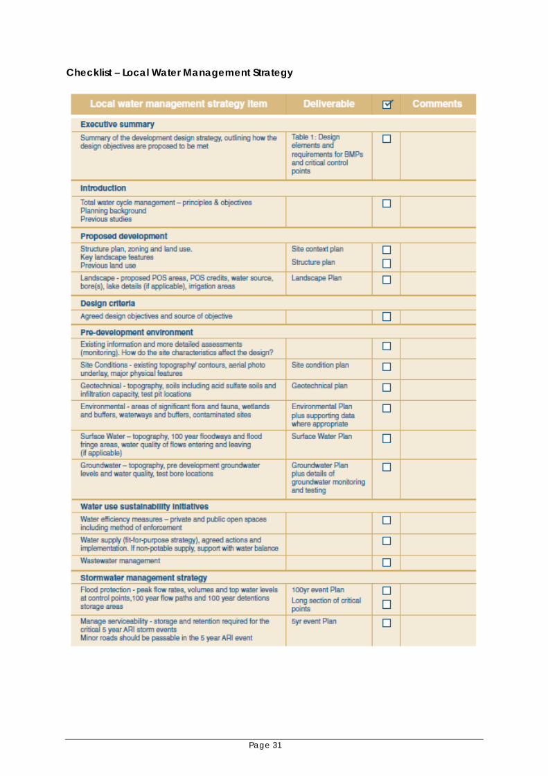
Checklist – Local Water Management Strategy

Page 32