locking nail - stryker - lgn - optech.pdf · if you have any difficulties with the technique, or...
TRANSCRIPT

LONGGAMMA®
Locking Nail

L O N G G A M M A ® L O C K I N G N A I L

C O N T E N T S
Acknowledgements:The Gamma® Locking Nail Operating Technique was compiled from the kindcontributions of leading surgeons in many countries; the principal authors andcommentators were:-
Dr. G. Taglang, Dr. A. Grosse, Strasbourg, France Dr. S.C. Halder, Halifax, UK Dr K.S. Leung, Hong Kong Dr. S. Boriani, Bologna, Italy
Our thanks are due to the many surgeons whose work has helped to confirmthe utility of the technique to present and future users of the Gamma® LockingNail family.
Warning: Bone screws referenced in this material are not approved for screwattachment or fixation to the posterior elements (pedicles) of the cervical,thoracic or lumbar spine.
DEVELOPMENT 4
INDICATIONS AND DESIGN FEATURES 6
COMPLETE OPERATING GUIDE 8
Pre-operative Planning 8
Patient Positioning, Fracture Reduction 9
Anteversion Guide 10
Incision & Entry Point 11
Preparation of Medullary Cavity 12
Reaming Technique 12
Nail Insertion 13
Lag Screw Targeting 14
Lag Screw Drilling 16
Lag Screw Selection and Insertion 17
Set Screw Insertion 18
Distal Locking 19
Final Checking 22
Extraction 23
Problem Solving 24
Implants and Instrumentation 28
Instrument Guide 32
3
This publication sets forth detailed recommended procedures for usingStryker Trauma devices and instruments. It offers guidance that you shouldheed, but, as with any such technical guide, each surgeon must consider theparticular needs of each patient and make appropriate adjustments whenand as required.

THE DEVELOPMENT OF THE LONG GAMMA ® LOCKING NAIL
4
The Long Gamma® Locking Nail is a specialized
development of the original Gamma® Locking Nail.
Stryker Trauma introduced the Long variant entirely in
response to demand from experienced surgeons worldwide
who wished to extend the benefits of the highly successful
standard Gamma Nail to even more patients.
Custom-made long nailsFollowing the world-wide introduction of the Gamma®
Locking Nail, experienced surgeons regularly requested
custom-made long variants from Stryker Trauma to deal with
certain specific clinical challenges. Versions with extended
distal stems were requested for such indications as:-
● Spiralling subtrochanteric fractures
● Ipsilateral neck and shaft fractures
● Prophylactic use – to avoid pathologic
fractures in osteoporotic bones in both
trochanteric and diaphyseal areas
For such applications, the advantages of using an
intramedullary locking nail in proximal fractures were now
extended for more distal fractures, i.e. increased security of
fixation, optimum biomechanical advantage, closed
operating technique and flexibility of locking options to
provide control of fracture fragments and allow
dynamization. The same benefits of early weight-bearing and
rapid rehabilitation, even in complex fractures, led more and
more surgeons to request these custom-made implants.
Long Gamma Nail introductionAfter more than five years’ experience with custom-made
implants, Stryker Trauma introduced the Long Gamma®
Locking Nail in 1993 as a standard implant to satisfy the
continuing demand for this specialized variant. Intended for
use by experienced surgeons already familiar with the
operating technique for the standard Gamma® Locking Nail,
the Long Gamma® Locking Nail was introduced in a range
of four lengths and three angles, handed left and right. The
success of the Long Gamma® Locking Nail has completely
justified its introduction, with tens of thousands of implants
supplied worldwide since launch.
Clinical pedigreePublished clinical studies for the Gamma® Locking Nail
family are among the most extensive for any surgical implant
currently available. They consistently illustrate how
successfully this evolving range of implants has achieved the
original design goals: to improve both the procedure and
prognosis for all grades of femoral fracture by extending the
application of the established intramedullary principle to set
a new standard for treatment:-
● Early weight-bearing1,2,3,4,5,6,7 through
superior strength and stability
● Reduced trauma3,4 through closed operating
technique3,4
● Low blood loss5,6 , low level of wound
problems5 and low risk of infection5
● More secure fracture fixation through better
biomechanics7
The clinical objective of the Long Gamma® Locking Nail,
as with the original Gamma® Locking Nail and the recently-
introduced Trochanteric Gamma® Locking Nail, is:-
Rapid mobilization, with fewer
complications, for better patient rehabilitation7
The operating technique for the Long Gamma® Locking
Nail is essentially the same as for the standard Gamma®
Locking Nail, the main variation being in the distal locking
process. The Long Gamma® Nail uses the same award-
winning Instrumentation* as for the rest of the Gamma®
family, obviating the need for further inventory and training
for both the surgeon and the theatre team.
The Long Gamma® Operating Technique is designed
specifically for the use of surgeons already familiar with the
standard Gamma® Locking Nail Operating Technique, as
this is an essential precondition for the use of the implant
itself. While the Long Gamma® Nail is indicated in relatively
infrequent clinical situations, Stryker Trauma believe that the
value of this implant as a surgical option is significant in
respect of the potential patient benefits; reduced surgical
trauma and early weight-bearing are both important
contributors to rapid mobilization and successful recovery
from fracture.

If you have any difficulties with the technique, or
questions about the Long Gamma® Locking Nail, please
contact your local Stryker Trauma representative or the office
shown on the back cover.
* Design-Innovation ’95, awarded for high design quality; Design Centre, Nordrhein Westfalen.
REFERENCES:1. Grosse A., Favreul E., Taglang G., “The Gamma® Nail; The results at theCTO Strasbourg” Paper presented at the International Symposium “RecentAdvances in Locking Nails”, Hong Kong, 1992. 2. Taglang G., Favreul E., “Results from the Centre de Traumatologie etd’Orthopédie, Strasbourg”: Paper presented at the Advanced Course inIntramedullary Locking Nailing, Courchevel, France, February 1991. 3. Leung K.S. et al, (Prince of Wales Hospital, Hong Kong), J Bone Joint Surg[Br] 1992; 74B, 3:345-51. 4. Boriani S. et al., results of Multicentric Italian Experience on the Gamma®
Nail. A report on 648 cases, Orthopedics 1991;14,12: 1307-1314. 5. Radford P.J., (University Hospital Queen’s Medical Centre, Nottingham,England): ”Comparison of results of the Gamma® Nail and Dynamic HipScrew in Extracapsular fractures of the Proximal Femur.”: Paper presented atAdvanced Course in Intramedullary Locking Nailing, Courchevel, France,February 1991. 6. Williams J.J., Cohen P.Z., Pittsburgh Orthopaedic Journal, 1990,Volume 1, pages 20 - 23. 7. De Groote W., Van Hoye M. et al, (St Jan General Hospital,Bruge/Middelheim General Hospital, Antwerp, Belgium): “The Gamma®
Locking Nail in the treatment of Long fractures” Article in press.
5

I N D I C A T I O N S A N D D E S I G N F E A T U R E S
6
IndicationsSpiralling subtrochanteric fracturesPertrochanteric fractures associated with shaft fracturesPathologic fractures in osteoporotic bone (includingprophylactic use) in both trochanteric and diaphyseal areasProximal or distal non-unions and malunions, revision procedures
X-ray illustrations of a range of Long Gamma® Locking Nailuses are shown on the inside back cover of this guide
Anatomical efficiencyThe Long Gamma® Locking Nail is designed for optimumefficiency both in operating technique and subsequentrehabilitation. There are two basic components, effectivetogether in a very wide range of clinical situations and fracturecomplexity. Insertion is entirely by closed surgical technique,minimizing trauma, blood loss and infection potential.
The NailThe nail itself incorporates several important mechanical designfeatures. The nail itself is unslotted and cannulated for guidewire controlled insertion. It has a 17 mm proximal diametertapering to 11 mm distally and is available in Left and Rightforms in lengths from 340 mm to 440 mm in 20 mm steps.Variations in femoral neck anatomy are accommodated by arange of neck angles available for the lag screw entry (125°,130°, 135°). The nail incorporates proximal anteversion of 10°.Two distal locking screws are inserted through the distal end ofthe nail to control rotation and telescoping.
The Lag ScrewThe lag screw, inserted through a small incision with the aid ofa radiolucent targeting device, incorporates a special slidinglock to provide dynamic compression with axial stability. Afterinsertion, a set screw inserted through the proximal head of thenail engages in one of four grooves in the lag screw. As theseare of asymmetrical depth profile, they allow the lag screw toslide in one direction, producing dynamic osteosynthesis bycompression during early weight-bearing. The lag screwincorporates a rounded nose profile and self-tapping threaddesigned for easy insertion and resistance to cut-out.
InstrumentationAs for the standard Gamma® Locking Nail, except that distaltargeting is accomplished using a free-hand technique or animage-intensifier-mounted targeting device.

The Gamma® advantage – strength and stabilityThe Long Gamma® Locking Nail offers significantly greaterstrength and stability in clinical use through the inherentbiomechanical advantage of the intramedullary system.
The biomechanical advantageAs the load-bearing axis of the Long Gamma® Locking Nail iscloser to the hip joint fulcrum, the effective lever on the implantand femur is significantly less than with an external plate,reduced by a factor equivalent to d/D in the diagram(approximately 25%*). The resultant force is transmitted directlydown the centre of the femur rather than through the manybone-weakening screws used in the side-plate system,increasing both the strength and reliability of the mechanicalrepair.
The rehabilitation advantageThe extra strength effectively gained by the biomechanicaladvantage of the Long Gamma® Locking Nail, combined withimproved control of axial telescoping and rotational instability,allows early weight-bearing even in complex or unstableproximal fractures. Earlier mobilization, combined withdynamic compression and less traumatic operative technique,increases the chance of successful patient recovery andreliable repair.
* Leung K.S., The Chinese University of Hong Kong: Gamma® AP Anthropometric Study of Proximal Femur, Jan 1991; Data on file, Stryker Trauma.
7
Proximal plug
Lag Screw
Nail
Set screw
Distal lockingscrews
Distal diameter 11 mm
Proximal diameter 17 mm
Lengths340 mm360 mm380 mm400 mm420 mm440 mm
Angles:125°, 130°& 135°
IND
ICATION
S &
DESIG
N FEATU
RES

C O M P L E T E O P E R A T I N G G U I D E
8
This surgical technique has been devised in consultation
with leading surgeons in many countries to be a basic
guide, particularly for less experienced users of the Long
Gamma® Locking Nail. It is acknowledged that several
alternative approaches to certain elements of the procedure
are practised, and may have advantages for particular
situations or surgeons. Parts of this guide may seem
simplistic or redundant for experienced readers, but are
included for the guidance of more junior staff.
A chart of the complete operating instrumentation is
folded into the back of this Operating Guide, and can be
folded out for easy reference in conjunction with the text that
follows. For easy identification, each instrument referred to
in the guide is keyed to the chart by a reference number,
and contains pictures of the Instrumentation and Implant
cases, shown on pages 30 and 31 complete with the
catalogue numbers of each item.
Pre-operative planningIn the majority of patients the standard 130° neck angle
can be used without difficulty. The 125° neck angle may be
needed in osteoarthritic coxa vara, and the 135° in coxa
valga. Where such variations in femoral anatomy require an
alternative, the following method may be used to confirm
the nail angle selection:-
Determination of neck angleA true anterior-posterior (A-P) pre-operative X-ray is required.
This can either be taken from the fractured hip, if an
accurate anatomical reduction has been obtained, or from
the contralateral hip. Check the femoral neck angle, i.e. the
angle between the femoral shaft mid-axis and the femoral
neck mid-axis, using a goniometer as shown.
Nail length selectionThe appropriate length of Long Gamma Locking Nail can
be chosen either by pre-operative planning using an X-ray of
the injured femur, or per-operatively as is the usual practice
in intramedullary nailing.
10
120
10
20
1615
1413
1211
109
87
6
0
30
29
28
27
26
25
24
23
22
21
20
33
32
31
9080
7060
50
40
30
20 10
0 10 2030
40
50
60
70
8090100
110
120
130
140
150
160
17018
017
016015
0140130
12010
100

P A T I E N T P O S I T I O N I N G & F R A C T U R E R E D U C T I O N
The procedure for patient positioning is normally the same
as for the standard Gamma (Figure 1); however, in fractures
that are particularly difficult to reduce, a transcondylar sterile
Steinmann pin may be used. The pin is fixed directly to the
orthopaedic table by an adaptable stirrup, and traction is
applied until anatomical reduction in the A-P view is
obtained (Figure 2).
Image intensifier positioningThe image intensifier is positioned so that anterior-posterior
and medio-lateral views of the trochanteric region of the
affected femur can be easily obtained. This position is best
achieved if the image intensifier can be positioned so that
the axis of rotation of the intensifier is centred on the femoral
neck of the affected femur (Figure 1).
Fracture reductionFor specific situations, special techniques have been
developed to aid successful fracture reduction, and these
are explained below. In general, however, the patient is
placed in a supine position on the fracture table and closed
reduction of the fracture is obtained as shown in figure 3.
Traction is applied to the fracture, keeping the leg
straight. Maintaining the traction, the leg is internally rotated
10 - 15 degrees to complete the reduction of the fracture;
the patella should then be either horizontal or slightly
internally rotated.
IMPORTANT Reduction should be achieved as
anatomically as possible. If this is not
achievable, reduction in one plane should be
achieved, leaving reduction in the other
plane to be achieved with the Long Gamma®
Locking Nail during insertion.
The unaffected leg is abducted as far as possible in order to
accommodate the image intensifier. The patient is then
prepared and draped as for standard hip fracture fixation,
but bear in mind that the incision is rather more proximal
when positioning the drapes
9
COM
PLETE OPERATIN
G G
UID
E
Figure 1
Figure 2
Figure 3

S P E C I A L T E C H N I Q U E S F O R F R A C T U R E R E D U C T I O N
10
Proximal fracturesThis type of fracture can be difficult to reduce because the
proximal fragment is in flexion due to the pull of the psoas
muscles, while the distal portion is in varus position due to
the pull of the adductor muscles (Figure 4).
To counter this mis-alignment, the trunk is bent to the
opposite side and maintained by a thoracic rest or by a
large drape. This extends the gluteus medius muscles,
externally rotating the proximal fragment into alignment and
exposing the trochanter for easier introduction of the nail
(Figure 5). The fractured limb is kept straight with the knee in
flexion (Figure 5), using the stirrup to avoid adduction. This
positioning externally rotates the distal portion. Reduction is
confirmed on the AP view.
Sub-trochanteric fractures cannot always be reduced
during positioning on the lateral view, because the proximal
fragment is drawn forward by the pull of the psoas muscles.
They must be reduced during the operation by means of the
special repositioning guide from the G & K system
miscellaneous tray (Figure 6).
Care must be taken when introducing the implant, as the
proximal fragment may rotate during insertion; the locking
nail must be carefully introduced exactly into the tip of the
greater trochanter, as far as possible by hand.
Anteversion guide insertionWith the image intensifier C-arm in the horizontal position
to give the lateral view of the femoral neck and head, a
2 mm Kirschner wire is inserted percutaneously, anterior to
the shaft and parallel to the axis of the femoral neck and
head. This is to provide a guide to the angle of anteversion
of the femoral neck during later insertion of the nail, during
which the targeting device is kept parallel to the Kirschner
wire in the coronal plane (Figure 7).
Alternatively, the guide wire can be inserted after the lag
screw guide sleeve is placed in position (see page 14).
Figure 7
Figure 6
Figure 5Figure 4

I N C I S I O N & E N T R Y P O I N T
INCISION
Determination of the soft tissue incision positionWith experience, the tip of the greater trochanter can be
located by palpation, and a horizontal skin incision of
approximately 5 cm is made from the greater trochanter to
the iliac crest. The incision is deepened through the fascia
lata, splitting the abductor muscle for approximately 3 cm
immediately above the tip of the greater trochanter, thus
exposing its tip. A self-retractor is put in place (Figure 8).
ENTRY POINT
Finding the bone entry pointThe correct entry point can be identified by touch; it is
located at the junction of the anterior third and posterior two-
thirds of the tip of the greater trochanter and on the tip itself.
Breaching the cortexThe medullary canal is opened, under image intensification
if necessary; use of the two-part curved awl (1) from the
G&K system miscellaneous tray is recommended, as its
conical sleeve is designed to be left in place to facilitate
passage of the reamer guide wire. Care must be taken to
ensure that the awl is not misplaced; this is more likely in the
anterior-posterior plane i.e. as seen on the lateral view.
The insertion point should be just on the tip of the
greater trochanter. If it is very medial (e.g. in the piriform
fossa) the nail will not go down the shaft properly, with the
danger of fracturing the femur.
When the entry point has been made, the reamer guide
wire is placed in position so that the proximal femur may be
prepared using flexible intramedullary reamers (Figure 9).
11
Figure 8
Figure 9

P R E P A R A T I O N O F T H E M E D U L L A R Y C A V I T Y
12
In order to accommodate the proximal end of the Long
Gamma® Locking Nail, the trochanteric region MUST be
reamed up to 17 mm (Figure 10).
The sub-trochanteric cavity must be 2 mm greater than
the distal diameter of the nail i.e. at least 13 mm; reaming
may be necessary in some patients to achieve this.
REAMING TECHNIQUE
A pre-curved guide wire is passed through the fracture site,
the head of the guide wire being centered in the distal
epiphysis.
Pass the reamer guide wire from the tip of the greater
trochanter into the shaft of the femur as shown in Figure 11,
using the Jacob’s chuck (2). Rotating the guide wire during
insertion will help it to take up the desired position and
avoid it coming out of a posterior fracture line.
Flexible reamers are used to ream the shaft of the femur
in stages starting from 9 mm diameter and increasing in
0.5 mm increments (Figure 12), in all cases to a minimum of
13 mm. Reaming is continued until the reamer starts to
bite/catch the endosteal surface. A-P as well as lateral
control of the reamer is necessary. Where there is
comminuted bone, reaming should be stopped at the
fracture site, penetration continued past the comminuted site
with the power drill off, then power reaming continued.
Care must be taken with flexible reamers to ensure that
the guide wire is not displaced laterally during reaming.
This could lead to resection of more bone on the lateral side
of the wire, which in turn would lead to an offset position
for the nail and a risk of fracturing the shaft.
Figure 11 Figure 12
Figure 10

N A I L I N S E R T I O N
NAIL INSERTION
Assembly of the targeting deviceThe selected nail is now assembled onto the carbon fibre
targeting device (3) as shown in Figure 13, ensuring that
the locating peg slots into the corresponding notch; it is held
by the nail holding bolt (4), and tightened using the socket
wrench (5) and the nail holding bolt screwdriver (6).
Nail/Lag Screw PositioningNail insertion is monitored with the image intensifier C-arm;
the projected axis of the lag screw should be
measured with a ruler on the monitor screen to
ensure that the lag screw will be positioned in the ideal
position. Visual estimation has proved to be
unreliable. To ensure correct positioning of the lag screw,
close attention must be given to the anteversion angle and
to the depth of insertion of the nail into the femoral canal.
Using anterior-posterior screening, the Long Gamma®
Locking Nail is inserted by hand (TAKE CARE TO
AVOID UNDUE FORCE – DO NOT USE A
HAMMER *) until the axis of the lag screw hole (visible as
crescent shapes on the screen) is lined up with the inferior
half of the femoral neck. The desired result of this is to
ultimately position the lag screw tip just below the centre
of the femoral head in the frontal plane (see Figure 19).
Note that the additional length of the Long Gamma® Nail
may in a small number of cases necessitate impaction for the
final 2-3 cms of insertion only, with the final impactor
(24) supplied. This should be carried out with extreme care;
if any undue resistance is detected, the nail should be
withdrawn and further reaming carried out.
CHECK: When the Long Gamma® Locking Nail is inserted
to its final depth the plane of the targeting device will be
parallel to the percutaneous guide wire positioned earlier
(see page 10). This ensures the correct degree of rotation to
align the lag screw holes with the angle of anteversion of
the femoral neck.
13
Figure 14
Figure 13
* NOTE: It is sometimes difficult to fully insert
the nail into the femur; one reason could be
that the medullary canal is too narrow. As the
Long Gamma® Locking Nail is a very strong,
rigid implant, it should not be forced into the
femur e.g. by hammering, as there is a danger
of fracturing the femur. If the nail will not go
into the femoral cavity far enough to allow
correct positioning of the lag screw,
furtherreaming should be carried out in 0.5
mm increments until the nail will go in fully.

L A G S C R E W T A R G E T I N G
14
Remove the reaming guide wire using the Jacob’s chuck (2),
ensuring that the targeting device (3) is supported to prevent
rotational movement of the Long Gamma® Nail. With the
nail now inserted to the correct depth, slide the targeting
sleeve (7) corresponding to the nail angle of the selected
Long Gamma® Locking Nail onto the end of the targeting
device (3) (Figure 15).
Please ensure before proceeding that the
nail holding bolt (4) is fully tightened.
The targeting device (3) may require support by an
assistant, to prevent its weight from externally rotating the
nail, until the next stage is completed.
Next, assemble the Kirschner wire guide sleeve (8) and the
guide sleeve for the lag screw (9), and pass them through
the targeting sleeve (7) to the level of the skin. This now
indicates the position for the small incision to be made,
which is developed down to the bone.
The guide sleeve assembly is now passed through the
incision to press firmly against the lateral cortex (Figure 16). If
the guide catches the fascia lata, twisting it will usually allow
it to pass through to the bone.
If not already inserted, the percutaneous
anteversion guide should now be placed
(see page 10).
The Kirschner wire guide sleeve (8) is removed and the lag
screw guide sleeve (9) is firmly abutted to the lateral cortex of
the femur to stabilize the targeting device (Figure 17). The
thumbwheel on the targeting sleeve (7) should be tightened
to lock the lag screw guide sleeve (9) in place and further
stabilize the targeting assembly (Figure 17 inset).
Figure 15
Figure 16 Figure 17

L A G S C R E W T A R G E T I N G
With the guide sleeve (9) firmly engaged in the cortex,
the awl (10) should be inserted and turned in order to pierce
the lateral cortex (Figure18). Check for correct positioning on
both anterior-posterior and lateral intensifier views.
NOTE: Before proceeding, check that the
guide wire for the flexible reamer used earlier
has been removed.
The Kirschner wire guide sleeve (8) is now re-inserted to
act as a guide for the lag screw guide wire (11), which is
inserted using the Jacob’s chuck (2).
The guide wire should be screwed into the subchondral
bone, checking for position on both the anterior-posterior and
lateral intensifier views.
Checking is essential if you are to ensure good lag
screw positioning. The tip of the guide wire (11) must be
placed in the inferior half of the femoral head in the frontal
plane, and on the midline in the lateral plane. The objective
is to place the lag screw below the centre of the femoral
head on the anterior-posterior view and centrally on the
lateral view, to decrease the risk of it cutting superiorly out of
the femoral head. (see Figure 19).
If the guide wire (11) is too anterior or posterior it must
be repositioned; this should seldom be necessary if the
anteversion-guiding percutaneous wire has been inserted
correctly (see page 10).
If the guide wire (11) is mispositioned, the first step is to
withdraw the guide wire itself, and then to withdraw the
nail. Rotate the nail in the appropriate direction and re-insert
as before. The guide wire is then re-drilled and control
screening is carried out as before.
15
Figure 18
Figure 19

L A G S C R E W D R I L L I N G
16
After achieving a satisfactory position for the guide wire
(11), the lag screw length required is measured using the
lag screw length measuring gauge (12). Before starting to
measure, ensure that the guide sleeve (9) is pressed firmly
against the lateral cortex of the femur.
Take the measuring gauge (12) and place it directly
under the guide wire (11) and against the Kirschner wire
guide sleeve (8) as shown in Figures 20a & b.
The measurement on the gauge is now transferred to the
adjustable stop on the lag screw step drill (13). It should be
noted that the adjustable stop is positioned with the chosen
length next to the stop on the side towards the drill
tip (Figure 21a). The collar is used to lock the stop in
position (Figure 21b).
NOTE: To ensure accurate lag screw length,
the Kirschner wire guide sleeve (8) must
remain in the lag screw guide sleeve (9), as
shown in figure 20b, when measuring lag
screw length.
Figure 20a
Figure 21a
Figure 21b
Figure 20b

L A G S C R E W S E L E C T I O N & I N S E R T I O N
The Kirschner wire guide sleeve (8) is now removed and the
lag screw step drill (13) is passed over the guide wire (11),
through the lag screw guide sleeve (9) (see Figure 22a).
The path for the lag screw is drilled using the Jacob’s chuck
(2). If exceptional resistance is encountered, a power drill
may be used with great care. Drilling should continue
until the stop impacts against the lag screw guide sleeve
(see Figure 22b), ensuring that the targeting
device is well supported to prevent backing out
and rotation.
If you check on the image intensifier at this stage you
should see the tip of the guide wire protruding slightly from
the step drill (Figure 22c). This is because the threaded
portion of the guide wire is deliberately excluded from the
drill measurement to prevent joint penetration by the drill.
The correct length lag screw is chosen by selecting a
size at least 5 mm longer than the measurement previously
made on the lag screw gauge (12) for drilling (see Figure
16). It is important that the lag screw protrudes
at least 5 mm from the lateral femoral cortex to
retain rotational stability and to permit sliding.
The correct size lag screw is now assembled with the
lag screwdriver (14). The end thumbwheel must be pulled
back, and the screw and driver connected as shown
(Figure 23).
After pulling back and connecting, the end thumbwheel
is tightened to secure the connection.
The lag screw is now passed over the guide wire (11),
through the lag screw guide sleeve (9), and threaded up to
the sub-chondral part of the head (Figure 24). If the guide
wire is inadvertently removed, then the screw may still be
passed without it provided that the lag screw guide sleeve is
still in contact with the cortex.
After tightening the screw ensure that the handle of the
lag screwdriver (14) is either parallel or perpendicular to the
targeting device (3) so that the set screw will engage in one
of the four lag screw grooves (see Figure 25c).
17
Figure 22a
Figure 23
Figure 22c
Figure 22b

S E T S C R E W I N S E R T I O N
18
The set screw is inserted through the opening in the carbon
fibre targeting device (3) and the nail holding bolt (4) at the
proximal end of the nail (Figure 25b). It is then tightened
fully using the set screwdriver (15) and socket wrench (5).
You may find this a little stiff because the screw has a nylon
insert in the threads to prevent spontaneous loosening.
The screw should then be unscrewed one quarter of a
turn to ensure free sliding of the lag screw. Ensure that the
set screw is still engaged in the groove by checking that the
lag screw cannot now be rotated with the lag screwdriver
(14).
Check the final position of the implant using the image
intensifier in the anterior-posterior and lateral planes (Figures
37a & b).
As distal locking of the Long Gamma Nail is not carried
out using the carbon fibre targeting device, this should now
be removed as follows: disconnect the lag screwdriver (14)
using the end thumbwheel, remove the lag screwdriver (14),
lag screw guide sleeve (9), guide wire (11), nail holding
bolt (4), targeting device (3) and sleeve (7).
A proximal plug (see Fig 25c) is available to prevent
ingrowth from becoming trapped in the proximal threads of
the nail, this is tightened using the set screwdriver (15).
Figure 24
Figure 25a
Figure 25c
Figure 25b

D I S T A L L O C K I N G
Distal Screw targetingVarious techniques can be used to guide drilling and
insertion of screws through the distal holes. The two methods
described here are (i) the use of the image-intensifier-
mounted target device and (ii) an alternative free-hand
technique.
Sighting the distal holesThe essential initial step in distal targeting is to position the
image intensifier so that the distal holes in the nail appear
perfectly round. If the holes appear to be elliptical in either
the vertical or horizontal planes, the image intensifier
position must be adjusted appropriately as shown
(Figures 26 and 27).
19
Figure 26
Figure 27

20
(i) GROSSE LAFFORGUE DEVICE
(IMAGE-INTENSIFIER-MOUNTED TARGET DEVICE)
Use of this targeting method can minimize radiation
exposure to the surgeon*, since this device fits into a
carriage that is mounted on the X-ray tube side of the image
intensifier, and can be manoeuvred remotely by the X-ray
technician.
After the X-ray beam is aligned to produce a perfectly
round hole on the monitor screen, the target device is folded
down in line with the beam and manoeuvred against the
patient’s thigh (Figure 28). The concentricity of the circles
made by the targeting device and the distal hole is verified,
making adjustments as necessary.
A skin incision is made, the pointed awl (18) is
introduced through the barrel of the sighting device and its
tip is used to pierce the lateral cortex (Figure 29).
The blue 5.5 mm drill guide sleeve (19) is passed
through the sighting device and both cortices are drilled
using the blue 5.5 mm drill (20) (Figure 30).
Figure 30
The drill (20) and guide sleeve (19) are removed and
the depth gauge (21) inserted through the sighting device to
determine the required screw length. The barrel of the
measuring gauge acts as a substitute for the normal guide,
being brought into contact with the bone (Figure 31).
Using the screwdriver (22), the fully-threaded 6.28 mm
screw is placed through the sighting barrel and driven
through both cortices (Figure 32).
The second screw is then targeted and placed in a
similar manner.
*Data compiled by Drs Taglang and Lafforgue at the Centrefor Traumatology and Orthopaedics, Strasbourg, France.
Figure 28
Figure 29
Figure 30
Figure 31
Figure 32

(ii) FREE-HAND TECHNIQUE
A universal free-hand distal targeting device has been
developed by Dr. D. Pennig and Prof. E. Brug for use with
the Long Gamma® Locking Nail.
The essential first step of using this device is to align the
image intensifier with the most distal screw hole of the nail
until a perfect circle is seen. A 4 mm Steinmann pin is
passed through the free-hand device and, using the image
intensifier, placed against the soft tissue to indicate the stab
wound incision site.
After the incision is made, and with the image-intensifier
on, use the free-hand device to place the Steinmann pin in
the exact centre of the visualized hole. Hold the point of the
pin firmly against the proximal cortex (Figure 33).
With the pin stationary, move the device until both
alignment rings appear as one and the pin appears to be a
dot in the centre of the single ring (Figure 34).
Use the mallet to tap the pin through the near cortex and
into the screw hole in the nail – up to but not into the far
cortex. Hold the targeting device by the handle for greater
stability (Figure 35).
Maintain the pin in place and remove the targeting
device, then introduce the special drill guide over the pin
and up to the near cortex (Figure 36). Using pliers, or the
Jacob’s chuck (2), remove the Steinmann pin. Hold the drill
guide firmly while the pin is removed.
Use the blue 5.5 mm drill bit (20) to drill through both
cortices. Remove the drill guide and drill. Measure using the
depth gauge, which has an integral sleeve that should
contact the near cortex to give the correct distance, and
place a screw of appropriate length in a free-hand fashion.
Repeat the steps to target the second hole.
21
Figure 33
Figure 34
Figure 35
Figure 36

F I N A L C H E C K I N G
22
FINAL CHECKING
Check the final position of the implant using the image
intensifier in the anterior-posterior and lateral planes (Figures
37a & b). Close the wounds (don’t forget the small stab
wound) with one drain proximally.
POSTOPERATIVE CARE ANDREHABILITATION
After the wound is closed, elastic bandage is applied from
the toes to the hip. Active and passive mobilization of the
lower limbs should be started immediately. The injured limb
is kept elevated. The drain is removed when the drainage
stops and usually within the first 48 hours. Walking can be
started on the third day.
For stable fractures with dynamic locking, full weight-
bearing walking can be started immediately.
For unstable fractures with static locking, immediate full
weight-bearing walking is allowed in fractures with good
bone contact.
For fractures with poor bone contact due to comminution
and large medial third fragment, partial weight-bearing
walking is allowed for the first 6 to 8 weeks. Full weight-
bearing walking can be commenced when there is a
bridging callus formed on the medial side as evident on the
follow up X-ray.
Dynamization of the fracture may be performed if
delayed union is noted between four and six months after
operation.
If the implants are going to be removed after the fracture
is healed, removal of the distal locking screw (dynamization)
six months prior to implant removal is recommended in order
to further improve the quality of the medial cortical bone.
Figure 37a Figure 37b

E X T R A C T I O N
EXTRACTION OF THE LONG GAMMA® LOCKING NAIL
Where extraction is indicated, please proceed as follows:-
Step IRemove the distal screws if fitted.
Step IIMake a small incision through the old scar below the
greater trochanter to expose the outer end of the lag screw.
Remove any bony ingrowth which may be obstructing
the outer end or internal thread of the lag screw as
necessary to ensure correct connection for the lag
screwdriver (14)
The lag screw guide wire (11) is then passed up to the
lag screw into the head of the femur. The lag screwdriver
(14) is passed over the guide wire, using the guide sleeve
(9) as a tissue protector, and engaged with the distal end of
the lag screw (Figure 38).
Check that ingrowth does not obstruct
secure engagement of the lag screwdriver (14),
otherwise the lag screw or driver may be
damaged and extraction made much more
difficult.
Step IIIAn incision is made over the proximal tip of the nail, the
proximal plug is removed, and the set screwdriver (15) is
engaged with the set screw. The screw is rotated
anticlockwise with the socket wrench (5) far enough to
disengage it from the lag screw groove (Figure 39). The set
screw does not need to be completely extracted.
Step IVThe lag screw is extracted by rotating the lag screwdriver
(14) in an anticlockwise direction. The lag screw guide wire
(11) must then be removed.
Step VThe nail extraction rod (23) is then threaded into the
proximal end of the nail (Figure 40). A sliding hammer
assembly (from the G & K system) is attached and the nail
extracted. Finally the wounds are closed.
23
EXTRACTIO
N &
PROBLEM
SOLV
ING
Figure 38
Figure 40
Figure 39

P R O B L E M S O L V I N G
24
PROBLEM SOLVING
Resistance to nail insertionSometimes it is difficult to introduce the nail far enough into
the femur. In the case below (Figure 41), the lower end of
the nail is impinging on the anterior cortex of the femur.
DO NOT hammer the targeting device (3). Some femurs
are highly curved anteriorly and hammering will break the
anterior cortex or the base of the greater trochanter.
The cortex should be reamed again using a 13 mm
reamer and the nail re-introduced (Figure 42).
If the nail will not go into the femoral cavity far enough
to allow correct positioning of the lag screw, further reaming
should be carried out in 0.5mm increments until the nail will
go in fully.
Figure 41
Figure 42

Bent guide wireIf insertion of the guide wire (11) is repeated in order to get
a satisfactory position, the wire may be bent due to its
passing through a previous track. This makes it difficult to
pass the step drill (13) over the bent wire (Figure 43).
If the guide wire (11) is only slightly bent then the step
drill (13) can be passed over it using a to and fro movement
(Figure 44).
If the guide wire (11) is markedly bent then it should be
removed and a new guide wire inserted; alternatively, the
step drill (13) can be passed smoothly up to the sub-
chondral bone without wire (Figure 45).
25
Figure 43
Figure 44 Figure 45

26
Posterior displacementIn the case of a comminuted fracture, there is a tendency for
the fracture to become displaced downwards, i.e.
posteriorly, making it difficult to pass the guide wire (11)
into the centre of the neck or head. This should be solved by
lifting the nail insertion targeting device (3).
Alternatively, the assistant could lift the greater trochanter
up with his hand, and support it with a sandbag. This will
maintain the neck and the femur in nearly the same axis, so
that it will be easy to pass the guide wire (11) through the
centre of the neck and head (Figures 46a, b, c). The
position should then be checked on both anterior-posterior
and lateral views using the image intensifier. Care is
required to avoid radiation risk to the assistant.
Figure 46a
Figure 46b
Figure 46c

N O T E S
27

I M P L A N T S & I N S T R U M E N T A T I O N
28
Long Gamma® Locking Nail – Screw Case
CAT. NO. DESCRIPTION SIZE
1600 - 2000 Screw Case Empty
1207 - 1285 Lag Screw 85 mm
1207 - 1209 Lag Screw 90 mm
1207 - 1295 Lag Screw 95 mm
1207 - 1210 Lag Screw 100 mm
1207 - 1215 Lag Screw 105 mm
1207 - 1211 Lag Screw 110 mm
1207 - 1212 Lag Screw 120 mm
1107 - 4035 Distal Screw 35 mm
1107 - 4040 Distal Screw 40 mm
1107 - 4045 Distal Screw 45 mm
1107 - 4050 Distal Screw 50 mm
1107 - 4055 Distal Screw 55 mm
1107 - 4060 Distal Screw 60 mm
1107 - 4065 Distal Screw 65 mm
1107 - 4070 Distal Screw 70 mm
1107 - 4075 Distal Screw 75 mm
1107 - 4080 Distal Screw 80 mm
1107 - 4085 Distal Screw 85 mm
1107 - 4090 Distal Screw 90 mm
1107 - 4095 Distal Screw 95 mm
1206 - 0822 Set Screw 8 x 27mm
1208 - 1212 Proximal Plug
Long Gamma® Locking Nail – Implant Cases
CAT. NO. DESCRIPTION SIZE
1634 - 1125 Long Gamma Nail 340 mm x 125° Right
1636 - 1125 Long Gamma Nail 360 mm x 125° Right
1638 - 1125 Long Gamma Nail 380 mm x 125° Right
1640 - 1125 Long Gamma Nail 400 mm x 125° Right
1684 - 1125 Long Gamma Nail 340 mm x 125° Left
1686 - 1125 Long Gamma Nail 360 mm x 125° Left
1688 - 1125 Long Gamma Nail 380 mm x 125° Left
1690 - 1125 Long Gamma Nail 400 mm x 125° Left
1600 - 1125 Implant Case 125° (empty)
Additional Lengths not stored on Tray
1642 - 1125 Long Gamma Nail 420 mm x 125° Right
1644 - 1125 Long Gamma Nail 440 mm x 125° Right
1692 - 1125 Long Gamma Nail 420 mm x 125° Left
1694 - 1125 Long Gamma Nail 440 mm x 125° Left
851207-1285
SET SCREW1206-0822
PLUG SCREW1208-1212
901207-1209
951207-1295
1001207-1210
1051207-1215
1101207-1211
1201207-1212
35
65 70 75 80 85 90 95
40 45 50 55 60
Ø6.
28Ø
6.28
125°

CAT. NO. DESCRIPTION SIZE
1634 - 1130 Long Gamma Nail 340 mm x 130° Right
1636 - 1130 Long Gamma Nail 360 mm x 130° Right
1638 - 1130 Long Gamma Nail 380 mm x 130° Right
1640 - 1130 Long Gamma Nail 400 mm x 130° Right
1684 - 1130 Long Gamma Nail 340 mm x 130° Left
1686 - 1130 Long Gamma Nail 360 mm x 130° Left
1688 - 1130 Long Gamma Nail 380 mm x 130° Left
1690 - 1130 Long Gamma Nail 400 mm x 130° Left
1600 - 1130 Implant Case 130° (empty)
Additional Lengths not stored on Tray
1642 - 1130 Long Gamma Nail 420 mm x 130° Right
1644 - 1130 Long Gamma Nail 440 mm x 130° Right
1692 - 1130 Long Gamma Nail 420 mm x 130° Left
1694 - 1130 Long Gamma Nail 440 mm x 130° Left
29
CAT. NO. DESCRIPTION SIZE
1634 - 1135 Long Gamma Nail 340 mm x 135° Right
1636 - 1135 Long Gamma Nail 360 mm x 135° Right
1638 - 1135 Long Gamma Nail 380 mm x 135° Right
1640 - 1135 Long Gamma Nail 400 mm x 135° Right
1684 - 1135 Long Gamma Nail 340 mm x 135° Left
1686 - 1135 Long Gamma Nail 360 mm x 135° Left
1688 - 1135 Long Gamma Nail 380 mm x 135° Left
1690 - 1135 Long Gamma Nail 400 mm x 135° Left
1600 - 1135 Implant Case 135° (empty)
Additional Lengths not stored on Tray
1642 - 1135 Long Gamma Nail 420 mm x 135° Right
1644 - 1135 Long Gamma Nail 440 mm x 135° Right
1692 - 1135 Long Gamma Nail 420 mm x 135° Left
1694 - 1135 Long Gamma Nail 440 mm x 135° Left
IMPLA
NTS &
INSTRU
MEN
TATION
130° 135°
I M P L A N T S & I N S T R U M E N T A T I O N
30
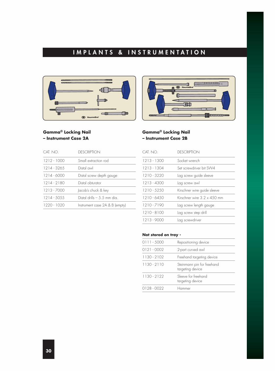
Gamma® Locking Nail – Instrument Case 2A
CAT. NO. DESCRIPTION
1212 - 1000 Small extraction rod
1214 - 3265 Distal awl
1214 - 6000 Distal screw depth gauge
1214 - 2180 Distal obturator
1213 - 7000 Jacob’s chuck & key
1214 - 5055 Distal drills – 5.5 mm dia.
1220 - 1020 Instrument case 2A & B (empty)
Gamma® Locking Nail – Instrument Case 2B
CAT. NO. DESCRIPTION
1213 - 1300 Socket wrench
1213 - 1304 Set screwdriver bit SW4
1210 - 3220 Lag screw guide sleeve
1213 - 4300 Lag screw awl
1210 - 5250 Kirschner wire guide sleeve
1210 - 6450 Kirschner wire 3.2 x 450 mm
1210 - 7190 Lag screw length gauge
1210 - 8100 Lag screw step drill
1213 - 9000 Lag screwdriver
Not stored on tray -
0111 - 5000 Repositioning device
0121 - 0002 2-part curved awl
1130 - 2102 Freehand targeting device
1130 - 2110 Steinmann pin for freehand targeting device
1130 - 2122 Sleeve for freehandtargeting device
0128 - 0022 Hammer

Gamma® Locking Nail – Instrument Case 3
CAT. NO. DESCRIPTION
1213 - 1000 Carbon fibre targeting device
1213 - 1100 Nail holding bolt
1213 - 1220 Screwdriver for nail holding bolt
1214 - 1160 Distal guide sleeve
1213 - 2125 Targeting sleeve 125°
1213 - 2130 Targeting sleeve 130°
1213 - 2135 Targeting sleeve 135°
1214 - 4172 Drill guide sleeve 5.5 mm
1214 - 5055 Distal drill bits – 5.5 mm
1214 - 7025 Distal screwdriver
1214 - 9000 Final Impactor
1220 - 1030 Instrument case 3 (empty)
31

I N S T R U M E N T G U I D E
32
2. Jacob’s chuck1. Two-part curved awl
4. Nail holding bolt
3. Carbon fibre targeting device
5. Socket wrench
6. Screwdriver for nail holding bolt
7. Targeting sleeve
8. Kirschner wire guide sleeve 9. Guide sleeve (for lag screw)
10. Awl (for lag screw)
11. Lag screw guide wire
13. Lag screw step drill
14. Lag screwdriver
15. Set screwdriver 16. Distal obturator
18. Awl (for distal screws)17. Distal guide sleeve
20. 5.5 mm Distal drill
19. Guide sleeve (for 5.5 mm distal drill)
22. Distal screwdriver
23. Nail extraction rod 24. Final impactor
21. Distal screw depth gauge
12. Lag screw length gauge

I N D I C A T I O N S
33
Fold
out
this
page
to s
how
in
strum
ent g
uide
for o
pera
ting
tech
niqu
e.
Extended subtrochanteric fracture Reduction 7 months post operation
Combined intertrochanteric andshaft fracture
Reduction 2 months post operation
Spinal fracture Nail inserted 8 months post operation
Pathological fracture
All X-ray photographs by courtesy of Dr. G. Taglang, Centre de Traumatolgie et d’Orthopédie, Strasbourg, France.
Proximal fixation Full length fixation

© 1999 Stryker Corporation. All rights reserved. Printed in the UK.The Stryker and Howmedica logos are registered trademarks.
To ensure the best quality of its products and their improvementsStryker reserves the right to modify all or part of their products.
Caution: Federal law (U.S.A.) restricts this device to sale by or on the order of a licensed physician.
GAMLG/1299/E
Manufactured by:Stryker Trauma GmbHProfessor Küntscher-Straße 1-5D-24232 SchönkirchenGermany