m2-3 tutorial 3 (1/2014) august 21,...
TRANSCRIPT

M2-3 Tutorial 3 (1/2014) August 21, 2014
1

2
Electronic Instrument
Disadvantage of moving coil meter • Low input impedance ⇒ High loading error
for voltmeter
–
Rm3
Rm2
Rm1 Rf
G
Rin
+ –
Op-Amp
–V
+V
Vin
+ Vout
I
DC Non-Inverting Amplifier
Higher input impedance (≈ 10 MΩ), Vin = I Rin Vout = I (Rf+Rg+Rin) Gain, Av = (Rf+Rg+Rin)/Rin = 1 + (Rf+Rg)/Rin
3
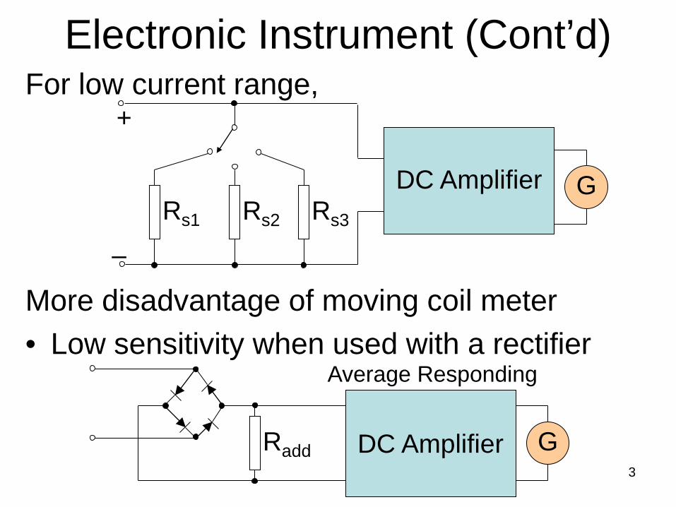
Electronic Instrument (Cont’d)
For low current range, More disadvantage of moving coil meter • Low sensitivity when used with a rectifier
Radd DC Amplifier G
Average Responding
–
+
Rs2 Rs1 Rs3
DC Amplifier G

Extending of the Ranges • The range of an ammeter or voltmeter can be
extended to measure high current/voltage values by using external shunt or multiplier connected to the basic movement that is set to the lowest current range (minimum internal additional resistors finest scale).
• Note that the range of the basic meter cannot be lowered, e.g. for 100 µA with 100 scale division the pointer deflects by only one division of 1 µA
4
External Shunt
Test Leads
Meter Set to
Lowest Current Range
External Multiplier
Test Leads
Meter Set to
Lowest Current Range

Requirements of Shunt Materials
• Soldering of joint should not cause a voltage drop (minimum thermo dielectric voltage drop).
• Resistance of different sizes and values must be soldered with minimum change in value (solderability).
5

Peak Responding AC Voltmeter • The difference to mean responding meters is the
use of storage capacitors with the half-wave rectifying diode. The capacitor charges to peak value of the applied voltage, Vc = Q/C and the meter then response to it.
• The capacitor discharges very slowly through the high input impedance of DC amplifier, so that a negligible small amount of current supplied by the circuit under test.
• The scale is then calibrated in RMS values.
6
7
PMMC Analog Multimeter Combination of • Appropriate shunts for direct current ranges, 50 µA - 10 A • Multipliers for direct voltage ranges, 100 mV - 3000 V • Rectifier for alternating currents designed for sine
wave, 10 mA - 10 A and 3 V - 3000 V (RMS) • Ohmmeter with 1.5 V, 3 V, 9 V battery,
2 kΩ - 20 MΩ • Accuracy, about ±1%FSD (DC), ±2%FSD (AC), ±3% Mid-Scale Ω
8
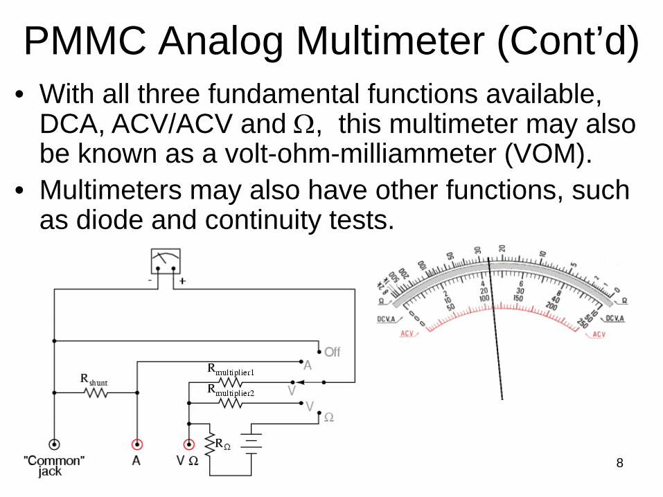
PMMC Analog Multimeter (Cont’d)
• With all three fundamental functions available, DCA, ACV/ACV and Ω, this multimeter may also be known as a volt-ohm-milliammeter (VOM).
• Multimeters may also have other functions, such as diode and continuity tests.
9
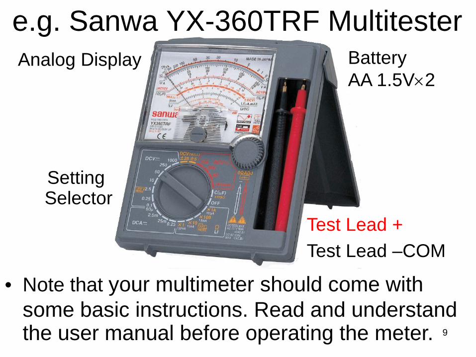
e.g. Sanwa YX-360TRF Multitester
Analog Display
Test Lead +
Test Lead –COM
Setting Selector
Battery AA 1.5V×2
• Note that your multimeter should come with some basic instructions. Read and understand the user manual before operating the meter.

Parallax Error • Because the pointer of the meter is usually a small
distance above the scale of the meter, parallax error can occur when the operator attempts to read the scale line that lines up with the pointer.
• To counter this, some meters include a mirror along the markings of the principal scale. It is improved by reading the scale so that the pointer and the reflection of the pointer are aligned.
10
DC Ammeter Precautions
• Never connect an ammeter across a source of EMF (electromotive force) because its low resistance would draw a high current and destroy the movement. Fuse is needed.
• Observe the correct polarity. Reverse current causes the meter to deflect against the mechanic stopper, which may damage the pointer movement.
• If the polarity is not known, insert the test leads momentarily. If the pointer goes down scale, remove immediately and reverse the polarity.
11

DC Ammeter Usage
• Set a function selector to the “DCmA” position.
• Set the range to the maximum current, i.e. 500 mA, to avoid pegging the meter or the pointer goes beyond the right of the scale.
12
×
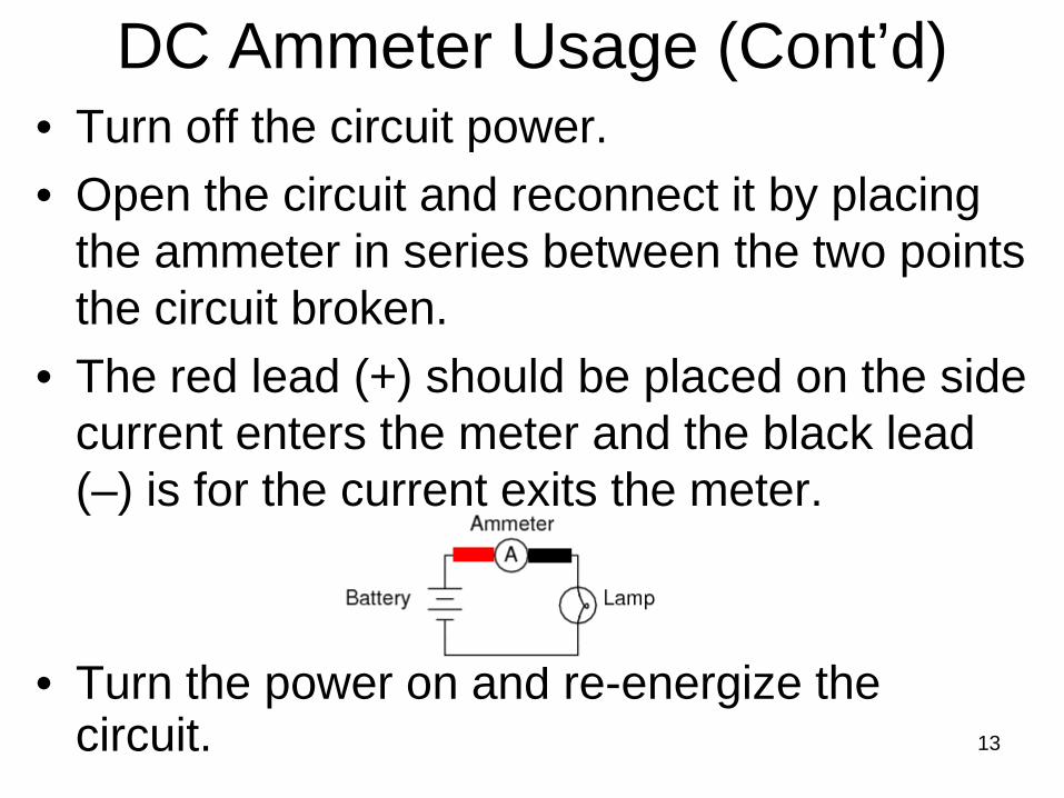
• Turn off the circuit power. • Open the circuit and reconnect it by placing
the ammeter in series between the two points the circuit broken.
• The red lead (+) should be placed on the side current enters the meter and the black lead (–) is for the current exits the meter.
• Turn the power on and re-energize the circuit.
DC Ammeter Usage (Cont’d)
13

• Adjust the range so that the pointer is as close to the farthest position to the right, i.e. 0.5 mA range should be selected.
DC Ammeter Usage (Cont’d)
14

• Read the linear scale with the range you selected, e.g. the maximum value is 5 mA.
• Multiply the reading on 0.5 mA range by 10 and the answer is 0.450×10 = 4.50 mA
• Tolerance ±e%FSD (DC)
DC Ammeter Usage (Cont’d)
15

• Set a function selector to the “Volts” position.
• Set the range to the maximum voltage, i.e. 500 V, to avoid the condition the pointer goes beyond the right of the scale.
DC Voltmeter Usage
16

• Turn off the circuit power. • Connect the voltmeter in parallel to two
terminals of the component we want to measure the voltage dropped across it.
• The red lead (+) should be placed on the side current enters the meter and the black lead (–) is for the current exits the meter.
• Turn the power on and re-energize the circuit.
DC Voltmeter Usage (Cont’d)
17

• Adjust the range so that the pointer is as close to the farthest position to the right, i.e. 15 V range should be selected.
DC Voltmeter Usage (Cont’d)
18
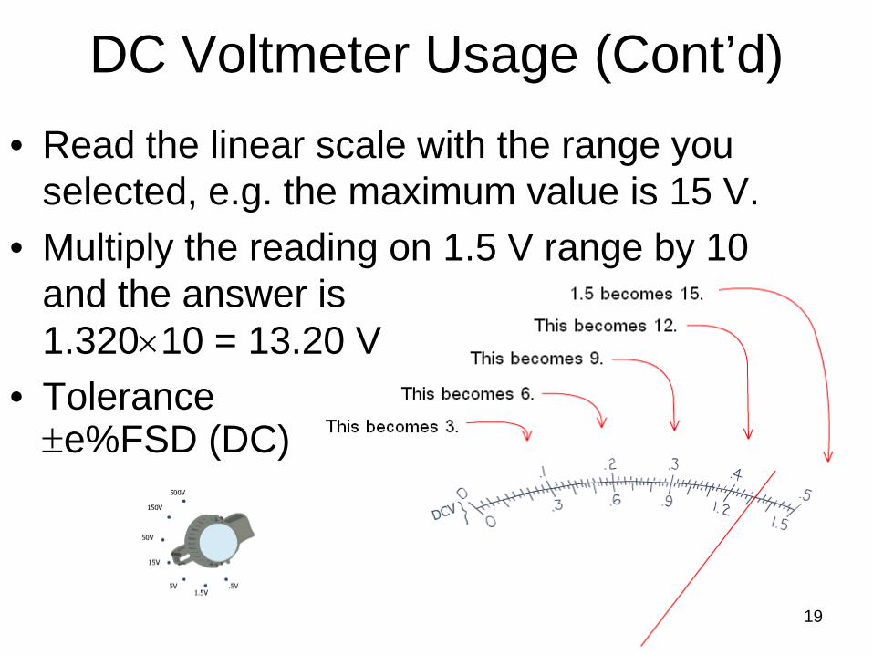
• Read the linear scale with the range you selected, e.g. the maximum value is 15 V.
• Multiply the reading on 1.5 V range by 10 and the answer is 1.320×10 = 13.20 V
• Tolerance ±e%FSD (DC)
DC Voltmeter Usage (Cont’d)
19

AC Voltmeter Usage
• Connect the meter across the circuit as same as DC voltmeter usage but it does not require correct application of the polarity .
• If the voltage range is unknown get the estimate value by setting the knob at the highest range at 1000 V, then lower the range until you could read it conveniently.
• The reading is in RMS value. 20

Ohmmeter Usage
• Set a function selector to the “Ohms” position. • Set the range to the smallest multiplier,
i.e. R×1. • Connect the ohmmeter to
the component being measured.
21
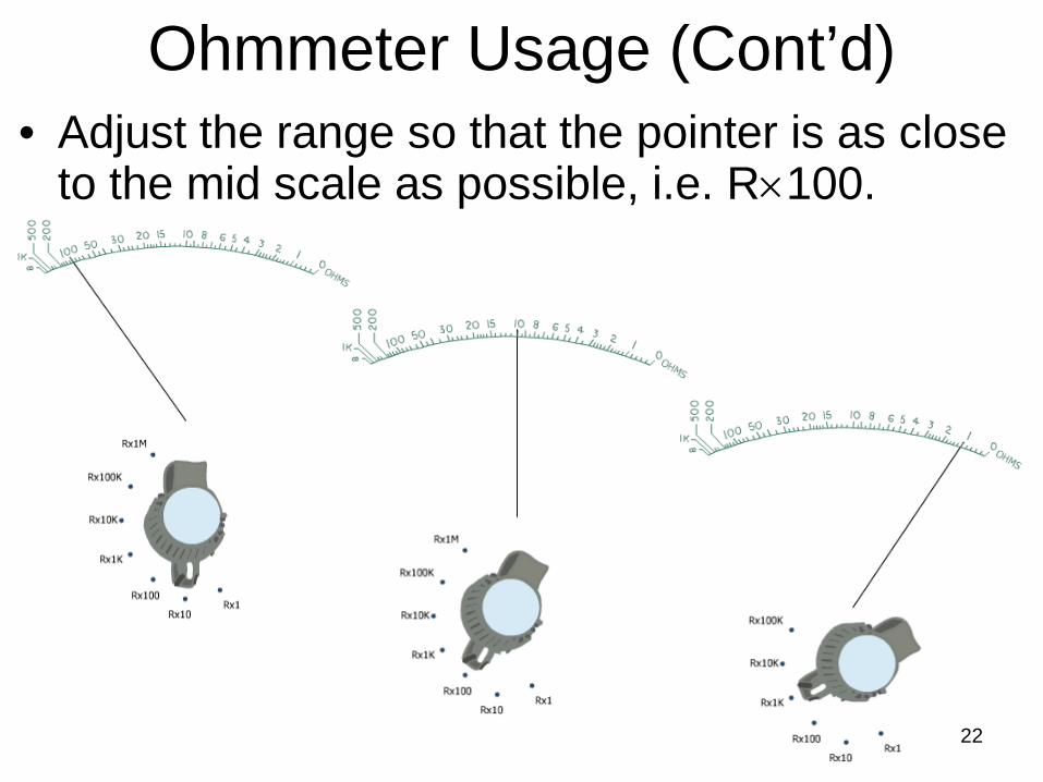
Ohmmeter Usage (Cont’d)
• Adjust the range so that the pointer is as close to the mid scale as possible, i.e. R×100.
22

Ohmmeter Usage (Cont’d)
• Remove the component and touch the test leads together. If the pointer is not at the zero line, turn 0-Ω adjust knob so that it becomes properly aligned.
23
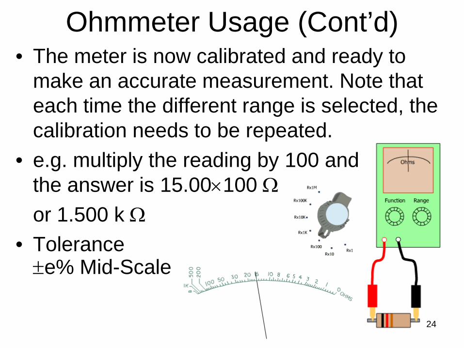
• The meter is now calibrated and ready to make an accurate measurement. Note that each time the different range is selected, the calibration needs to be repeated.
• e.g. multiply the reading by 100 and the answer is 15.00×100 Ω
or 1.500 k Ω • Tolerance ±e% Mid-Scale
Ohmmeter Usage (Cont’d)
24