main aspects and results of level 2 psa for knpp wwer … aspects and results of level... ·...
TRANSCRIPT

Proceedings of the 10th International Conference on Nuclear Option in Countries with Small and Medium Electricity Grids Zadar, Croatia, 1-4 June 2014 Paper No. 146
146-1
Main Aspects And Results Of Level 2 PSA For KNPP WWER-1000/B320
Kaliopa Mancheva, Kiril Tzenkov, Evgeni Borisov “Risk Engineering” Ltd
10 Vihren Street, Sofia, Bulgaria [email protected], Kiril.Tzenkov@ riskeng.bg, Evgeni. [email protected]
ABSTRACT
The PSA Level 2 for Kozloduy NPP (KNPP) is an update of a previous study with wider scope of analysis. The previous study represented the status of the units up to 2001. The current PSA Level 2 is based on the PSA Level 1 and represents the status of the units up to 2007 year concerning the systems and procedures included in PSA level 1 and status up to 2011 for the systems and procedures (e.g. SAMG) related to containment and severe accident aspects. The study is performed after the PSA level 1 has been finished and approved by the customer. Compare to the older analysis all modes of operation for analyzed in PSA level 1 event groups as well Spent Fuel Pool accidents are investigated.
The analysis consists of both deterministic and probabilistic analysis. As part of deterministic analysis a contemporary containment strength analysis and accident progression deterministic analysis using the last version of MELCOR are performed. The probabilistic analysis contains of two parts: Interface PSA and CET are calculated using Riskspectrum program code. Two types of models for CET have been developed: one for conditional probabilities calculations and a set of simplified CET’s for each PDS group – for integral model. The purpose of the first model is to be able to perform quick calculations and for sensitivity analyses as well. The simplified CET’s are used for integral calculation of the model.
Source Term analysis is mainly based on the MELCOR analyses results. All characteristics of the releases have been defined, i.e. location, mass, energy of radionuclide groups and activity of the released isotopes (most important are reported only).
The main goals of the study are to analyze the status of the containment, systems designed to prevent containment failure and operator action required under the severe accident and to give quantitative assessment of the risk parameter LERF (Large Early Release Frequency).
This report will present main results, finding and conclusions of the analysis. Based on the results, the effectiveness of the current means and SAMG are assessed qualitatively.
1 INTRODUCTION
Units 5 and 6 of Kozloduy are of VVER-1000/B320 type of reactors. These are pressurized light water reactors with four loops, horizontal SG and with 3 independent and of 100 % capacity safety systems trains.
The PSA Level 2 analysis is partially an update of the currently available PSA L2 study for Units 5 and 6 of Kozloduy NPP (KNPP) and partially entirely new analysis. The new study includes in addition to the previous one all low power and shutdown modes and Spent Fuel Pool (SFP) analysis. The scope of the new study covers:
• Internal IE’s • Internal Flooding; • Internal Fires;

146-2
• Seismic Hazard, All power levels and shutdown of the reactor installation and SFP (full power mode is
excluded from the analysis of SFP) are analyzed. Moreover, the new study is based on different PSA tools and the latest MELCOR version is
used for accident progression analysis. The old study is developed using SAPHIRE for interface part and EVNTRE code for Containment Event Tree analysis. The current study is performed using RiskSpectrum for interface and CET part of the analysis, i.e. the PSA part of the modeling. In this sense, the current study can be treated as an entirely new study.
The analysis structure is shown on Figure 1. The figure pictures the different tasks performed in the study and relations between them.
PSA L1$L2 Interface
MELCOR’s Models Development (Reactor
and SFP)
Melcor Calc
Containment Structural model development
Containment Event Trees
Melcor Clacs
Melcor CalcsSource Term Analysis
Phenomenon Analysis
Primary Side structural model development
Containment Structural Analysis
Conclusions and Insights
Quantitative Assessment
Recomendations
Additional Assessments
System & Human Error Analysis
Sensitivity, Uncertainty and Importance
Analysis
Primary Side Structural Analysis
Input Data Analysis
Figure 1: PSA Level 2 Analysis structure Goals of the study are in compliance with the recommendations given in IAEA SSG-4
document (reference).
2 INTERFACE BETWEEN PSA LEVEL 1 AND LEVEL 2
The interface analysis links PSA L1 and L2 models in way that all of the sequences in PSA L1 are grouped in so called Plant Damage States (PDS), which further are analyzed in CET model. The analysis groups sequences based on their similar characteristics in order CET model can treat particular PDS as one severe accident scenario. This means that the severe accident progression for all of the sequences grouped in one PDS are expected to be identical or similar. Therefore, grouping process is performed using so called attributes or characteristics of the sequences, which are identical or similar for all the sequences in the PDS and are important considering the severe accident progression.
For the sequences with no bypass of Containment, the following attributes are used: • IE’s class – Large LOCA, Small Small LOCA, Transient, TBO and ATWS classes are
analyzed; • Primary Side Pressure at core damage moment:
- Pressure is above 110 kgf/cm2 – only make up system can be used; - Between 21 kgf/cm2 and 110 kgf/cm2 – HPIS can be used; - Bellow 21 kgf/cm2 – LPIS can be used;

146-3
• Containment Status – isolated, not isolated or opened; • Spray System Status – available in recirculation mode or failed; • AC Power Supply availability – At least 1 out 3 Safety 6 kV Switchgears is available
or TBO; • ECCS availability – 1 out of 3 HPIP or LPIP is available, 1 out of 3 Make-up pumps is
available, all systems are failed ; • Time to Core damage:
- Core damage occurs before 12-th hour after EP is onset; - Core damage occurs after 12-th and before 24-th hour after EP is onset; - Core damage occurs after 24-th and before 48-th hour after EP is onset; - Core damage occurs after 48-th hour after EP is onset.
For the bypass events the attributes are as follows; • IE’s Class – Medium or Large Break, SGTR and Interface LOCA; • SDA status – failed in open position or operate in cycling mode; • SGSV status – failed in open position or operate in cycling mode; • Primary Side Pressure – Bellow or above SDA (72 kgf/cm2) set point for opening;
For Spent fuel Pool, the attributes are similar, although, systems for injection into the SFP are not the same and some of the attributes used for reactor installation are skipped (e.g. pressure at fuel damage moment).
The distribution of different major PDS groups for reactor installation and SFP are shown on Figure 2.
RI analysis SFP analysis
Figure 2: PDS distribution
3 ACCIDENT PROGRESSION ANALYSIS – MELCOR CALCULATIONS
Deterministic part of accident progression analysis has been performed using the last version of MELCOR code, i.e. version 2.1. The results of the analysis are used for containment event tree construction, bases of conditional probabilities assignment for most of the phenomena, quantitative analysis of the source term.
Several models are developed to envelope different POS (Plant Operating State) for reactor installation and SFP. The choice of the POS’s is done based on the PSA level 1 and respectively PSA L1&L2 interface results. The models that are used consequently in the analysis are:
• Full power (POS0) model for reactor installation; • Cold state (POS06) model for reactor installation; • Shutdown state with open reactor (POS08) model for reactor installation; • Shutdown state with unloaded reactor (POS10) model for Spent fuel pool.

146-4
3.1 Reactor installation modeling
Two different nodalizations have been used – simple one for LBLOCA sequences and the detailed one for all others (which includes Small Small LOCA, Transients and ATWS).
Generally, the differences between two nodalizations is in the core region, where a number of 30 control volumes (CV) has been used for detailed nodalizations and 5 CV for simplified one. The detailed nodalization gives more sophisticated behavior of internal flows and consequently more realistic simulation of the slow core degradation. The control volume model for Primary Side is represented by 112 volumes in detailed nodalization and by 87 in the simple one. The nodalizations for the current study are shown on Figure 3.
010-020010-020020-034
020-035 020-033
040-050
033-050032-050
031-050034-050
035-050
CV0
34
CV0
60
020-033
CV0
10
030-060
CV0
32
020-031
CV0
35
031-032034-035
033-034
035-040
24.930
CV0
33
CV0
31
020-032
032-050
020-040 020-035020-034
031-050
040-050040-060
035-050 033-050034-050
032-033
CV0
33
CV0
34
CV0
40
CV070
CV0
6002
0-06
0
CV020
CV0
10
032-033
CV0
32
033-034
040-060
CV0
35
031-032034-035
CV0
31
035-040
020-031
29,440
030-060
18.419
22.928
16.899
070-050
060-070
16.899
26.953
060-070
CV070
020-
060
CV020
CV050
CV0
40
18.419
070-050
22.928
24.930
18.519
020-040
CV050
020-03218.519
26.953
29,440
010-020
CV032
CV016
CV047
CV014 CV024
CV052
CV037
CV042
CV056
CV012
CV023
CV045
CV036
CV057
CV046
CV054
CV055CV025
CV044
CV022
CV043
CV034
CV035CV015
CV050
CV027
CV013 CV053
CV017
CV033
CV026
25.275
24.647
22.928
16.899
070-092
24.930
26.753
CV092091-092
23.728CV091
020-040
040-060
CV01
0
CV04
0
CV020
18.519 18.419
29,440
060-070
X=1,2,3,4109-458
CV458 CV458
29.5545
28.7565
28,0395
21,065
x02-x20
CV110
x02-x03
20,640
CVx24
CVx22CVx21
x08-x09
23.900
CVx07
CVx26x02-x23
CVx20
CVx28x25-x05
27,938 27,938
CVx09
CVx0
4
29.140
CVx
06
20,21520,215
x28-x05
29.140
30,128
24.000
CVx27
CVx0
8
CVx25
109-110*
x27-x28
x21-x22CVx0
2
x20-x21
CVx23
22,18
x23-x24
x07-x08
x26-x27
x24-x25
32,17
CVx0
5
x00-x04
x05-x06
CVx0
1
x06-x07
CVx0
3
x04-x05
CVx00
32,17
30,128
x01-x02
x02-x26
25.700
x22-x05
110-458
CV070
CV0
60
035-040
020-
060
050-091
26.125
047-050 057-050037-050027-050017-050040-050
057-060047-060037-060027-060017-060
020-052020-042
020-032020-022
020-012
050-x00 25.700
x09-010 (110-010*) 23.900
24.325
23.475
Simple Nodalization Detailed Nodalization
Figure 3: Primary Side Nodalizations For open reactor modes, the nodalization is changed to account for absence of some of the
internal structure and reactor cover. Additionally, the connections between different parts of Primary side (SG, Pressurizer and Reactor) and gas removal system are simulated. The nodalization of the model is shown on Figure 4.
144-811
811-813
x03-811
010-020
x04-811
034-035
x00-x04
CVx20
CV050
x27-x28
25.275
040-050
27.55
18.419
x01-x02
x08-x09
020-032
16.899
x04-x05
x07-x08
CV01
0
033-034
CVx0
4
CVx0
8
24.000
32,17
x05-x06
CVx28x23-x24
x06-x07
22.928
24.930
x09-010 (110-010*)
x24-x25
CVx0
3
x21-x22
25.700
29.140
CVx0
1
CVx
05
22,18
x26-x27
031-032
CVx27
x20-x21CVx
02
27,938
x25-x05
24.325
CVx0026.125
109-110*
23.475
20,215
x28-x05
x02-x23CVx25
x02-x20
30,128
32,17
30,128
29.140
020-031
20,215
CVx0
6
CVx09
020-040
CVx24
23.900
CVx21
CVx26
CVx07 20,640
x02-x26
CVx22x22-x05
x02-x03
CV110
CV04
0
21,065
23.900
CV0
34
050-x00
CV0
33
25.700
032-033
020-
060
CV020
CV03
2
28,0395
28.7565
033-050
CV03
5
29.5545
035-040
CV03
1
034-050
020-035020-034
020-033
031-050032-050
X=1,2,3,4
035-050
140-14322.64
CV463
20.113
CV400
19.767
CV140
CV81134.323
23.475
FL142 FL141
32.15
463-050
19.94
CV143
FL143-144
CV144
400-140
TQn2đĺ ě î í ňí î đŕ çőëŕ ćäŕ í ĺ(î ňâĺ ćäŕ í ĺ í ŕ ňî ďëî í î ńčňĺ ë)CV407
25.70
CV140
CV813
CV140
813-463
31.353
TQn2đĺ ě î í ňí î đŕ çőëŕ ćäŕ í ĺ(ďî äŕ âŕ í ĺ í ŕ ňî ďëî í î ńčňĺ ë)CV100
27,938
18.519
CVx23
31.353
CV140
CV140
25.70400-140
CV144
FL143-144
CV143
19.94
32.15
FL141FL142
23.475
34.323
CV140
19.767
CV400
20.113
22.64
140-143
Figure 4: Primary Side Nodalization for open reactor
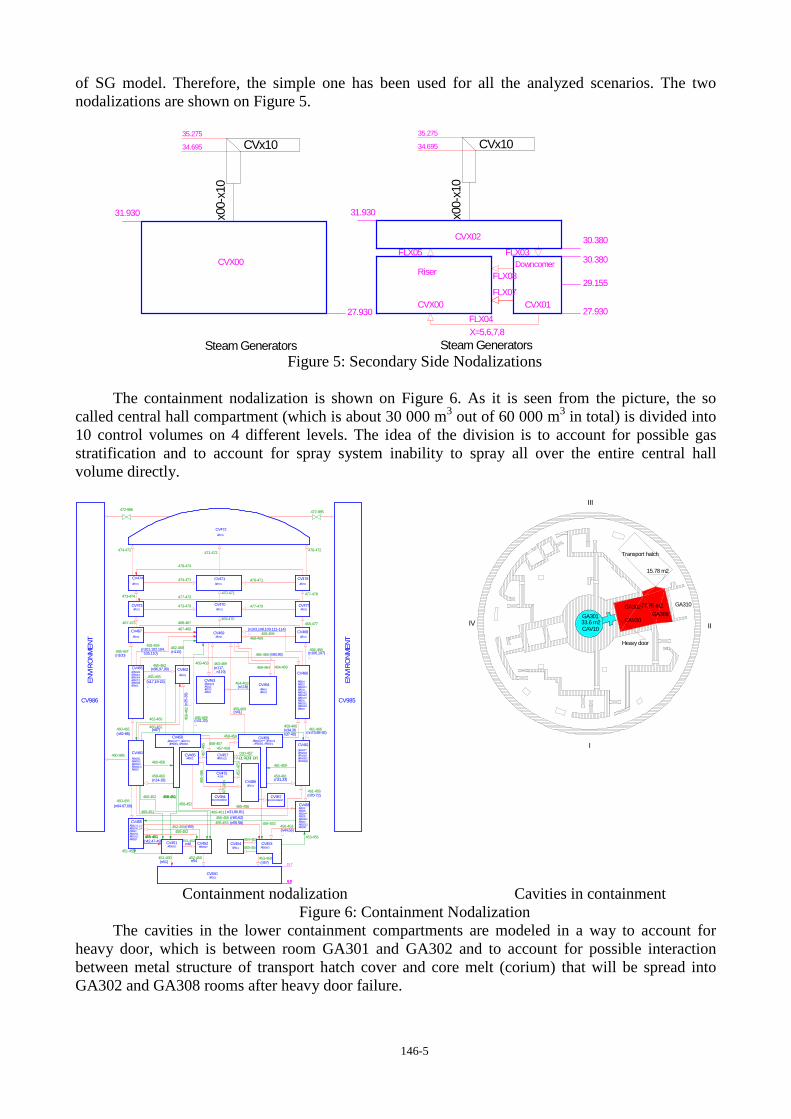
More simplified nodalization is used for the secondary side. Two different nodalizations of secondary side of steam generator have been tested in order to choose the most appropriate, first one with one control volume and second one with three control volumes per SG (riser, downcomer and steam part). The results for 5 different transients showed that the more detailed nodalization slows down calculations significantly, about 2 times, without any significant change in the behavior
146-5
of SG model. Therefore, the simple one has been used for all the analyzed scenarios. The two nodalizations are shown on Figure 5.
Steam Generators Steam Generators
CVx10
x00-
x10
CVx10
x00-
x10
FLX08
CVX02
DowncomerFLX03
CVX00
CVX00FLX04
30.380
X=5,6,7,8
FLX05
CVX01
31.930
35.275
29.155
31.930
Riser
34.695
35.275
34.695
27.930
30.380
FLX07
27.930
Figure 5: Secondary Side Nodalizations
The containment nodalization is shown on Figure 6. As it is seen from the picture, the so
called central hall compartment (which is about 30 000 m3 out of 60 000 m3 in total) is divided into 10 control volumes on 4 different levels. The idea of the division is to account for possible gas stratification and to account for spray system inability to spray all over the entire central hall volume directly.
(n17,19-24)
(n57)
(n93,95)
ĂŔ304ĂŔ312ĂŔ502/1ĂŔ503ĂŔ504/2ĂŔ504/3ĂŔ507/2ĂŔ601ĂŔ603/1ĂŔ603/3ĂŔ604
ĂŔ301(2)***, ĂŔ407/2ĂŔ506/2, ĂŔ606/1
(nn73,88-92)
(n96,97,99)
ĂŔ301(1)
(n59)
(n42,47-49)
ĂŔ701
ĂŔ701
ĂŔ301(3)ĂŔ312ĂŔ313ĂŔ501
ĂŔ301(2)***, ĂŔ407/1ĂŔ506/1, ĂŔ606/2
(n31,33)A336
ĂŔ311 ĂŔ306/3
ĂŔ302ĂŔ303ĂŔ304**ĂŔ305ĂŔ309/2ĂŔ310ĂŔ315/3ĂŔ308*
ĂŔ304**ĂŔ405/4ĂŔ405/5ĂŔ405/6ĂŔ406(2)
(n44,56)
(n55,58)
ĂŔ701
n54
(n118)
ĂŔ701
(n34,36n37-40)
ĂŔ403
(n64-67,69)ENVIROMENT
(n106,107)
(n14-18)
(n25
-28)
ĂŔ401ĂŔ402
ĂŔ405/1ĂŔ405/2ĂŔ405/3ĂŔ406(1)ĂŔ505
ĂŔ701
( n31,80,81)
(n70-72)
ĂŔ306/2
(n115)
(n103,108,109,111-114)
ĂŔ201
(n100)
(n31,33)
(n51)
ENVIROMENT
(n41)
n46
(n87)
ĂŔ701
(n117,n119)
(n60,62)
ĂŔ701ĂŔ701
ĂŔ701
(n82-86)
ĂŔ302
ĂŔ101
ĂŔ306/1
(n101,102,104,105,110)
ĂŔ701
ĂŔ502/2ĂŔ504/1ĂŔ504/4ĂŔ507/1ĂŔ603/2ĂŔ605
ĂŔ307/1,2,3ĂŔ309/1,3,4ĂŔ314ĂŔ315/1ĂŔ315/2ĂŔ308*
460-455
466-469
465-462
456-455
453-454
453-456
460-452
459-466461-466
477-470
478-471
465-467
458-469
462-469
455-453
475-
984
469-464
461-459
471-472
455-451
485-456
464-469
458-459
458-
462
456-453
468-477
455-451
458-465
473-470
477-473470-471
466-468
469-470
461-456
478-472
468-469
462-460
472-986
020-457
485-
486
458-457457-459
457-
485
478-474
473-474
454-453
459-461
452-450
467-473
463-469
451-450
464-463
460-462
458-451
465-466
453-450
458-460
467-469
458-452
451-452
465-469
460-465
460-458
455-452
468-467
477-478
452-455
458-451
474-472
459-453
451-455
460-451
459-469
460-986
469-463
472-985
457-
475
460-461
î ň ĐĹŔĘŇÎ ĐŔ
474-471
CV456
CV458
CV452 CV454
CV450
CV468
CV465
CV469
CV472
CV470CV473
CV485
CV463
CV986 CV985
CV475
ENVI
RONM
ENT
CV987
ENVI
RONM
ENT
CV462
CV984
CV466
CV464
CV467
CV474 CV471 CV478
CV477
CV453
CV459
CV461
CV455
CV451
CV460
CV486
CV457
6.9
13.7
6.96.9
II
I
33.6 m2
15.78 m2
Heavy door
III
CAV10
77.75 m2
IV
GA310GA302GA308GA301
CAV30
Transport hatch
Containment nodalization Cavities in containment Figure 6: Containment Nodalization
The cavities in the lower containment compartments are modeled in a way to account for heavy door, which is between room GA301 and GA302 and to account for possible interaction between metal structure of transport hatch cover and core melt (corium) that will be spread into GA302 and GA308 rooms after heavy door failure.
146-6
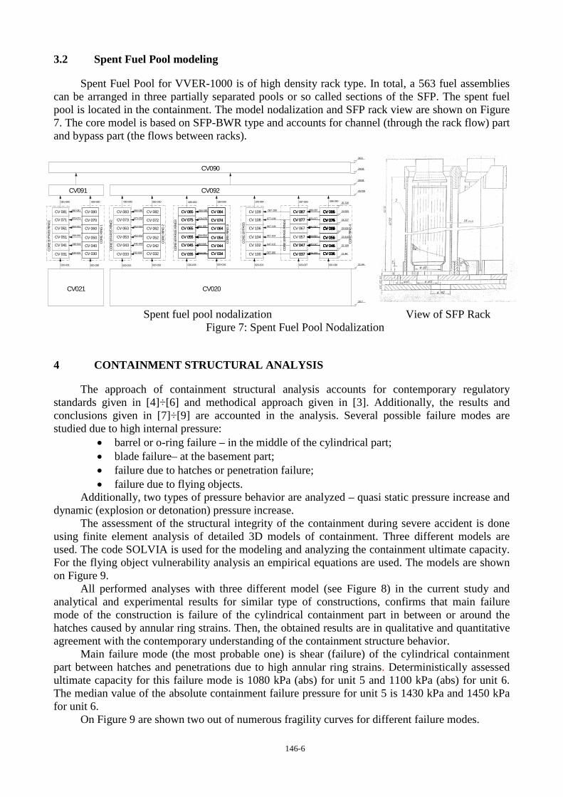
3.2 Spent Fuel Pool modeling
Spent Fuel Pool for VVER-1000 is of high density rack type. In total, a 563 fuel assemblies can be arranged in three partially separated pools or so called sections of the SFP. The spent fuel pool is located in the containment. The model nodalization and SFP rack view are shown on Figure 7. The core model is based on SFP-BWR type and accounts for channel (through the rack flow) part and bypass part (the flows between racks).
28.83
CV092CV091
CV021
CV090
36.9
CV 056
086-090
CV 075
CV 085CV 083
CV 047
CV 061
CV 033
CO
RE R
ING
2
CV 042
CV 085
CV 031
CV 081 CV 082
CV 045
CO
RE
BYPA
SS R
ING
1 CV 075
CV 087
CV 070CV 071
COR
E BY
PASS
RIN
G3
CV 086
CV 066
CV 074
CV 084
CV 034
CV 055
CV 086
CV 050
CV 076CV 076
CV 087
CV 076
CO
RE R
ING
4
CV020
CV 086
CV 066
CV 046CV 047 CV 046
CV 066
CV 056
CV 036
020-033 020-035020-032 020-034
083-090 084-090082-090 109-090
062-063
CV 046
COR
E BY
PASS
RIN
G4
080-090
CV 030
060-061
036-037
081-090
037-100
084-085080-081
032-033 CV 034
052-053
084-085
020-100
CV 064
056-057
CV 067
046-047
034-035
CV 044
CV 065
074-075
086-087
054-055
CV 062
CV 040 044-045
CV 080
CV 100
076-077
CV 064
047-102
CV 057C
ORE
BYP
ASS
CV 035
CV 060 066-067
CV 102
CV 104
CV 106C
ORE
RIN
G 3
CV 041
CV 072
CV 045
CV 055
CV 035
CV 053
CV 066
CV 084
CV 074 CV 076CV 076
CV 036CV 036 21.44
CV 066
CV 056
24.933
CV 037
CV 056
CV 066
CV 076
CV 066
CV 036
CV 066
22.815
23.521
24.227
CV 046 22.109
20.7
25.725
25.725
CV 077
CV 109
CV 054
077-108
020-037
067-106
CV 076
020-030
057-104
020-031
CV 076
21.44
CV 086
CV 037030-031
087-109
CV 108
CV 054
087-090
020-036
CV 077CV 073
085-090
CORE
RIN
G 1
CV 052
072-073
050-051
070-071
064-065
CV 043
COR
E BY
PASS
RIN
G2
042-043
CV 032
CV 065CV 063
CV 051
CV 044040-041
28.83
Spent fuel pool nodalization View of SFP Rack
Figure 7: Spent Fuel Pool Nodalization
4 CONTAINMENT STRUCTURAL ANALYSIS
The approach of containment structural analysis accounts for contemporary regulatory standards given in [4]÷[6] and methodical approach given in [3]. Additionally, the results and conclusions given in [7]÷[9] are accounted in the analysis. Several possible failure modes are studied due to high internal pressure:
• barrel or o-ring failure – in the middle of the cylindrical part; • blade failure– at the basement part; • failure due to hatches or penetration failure; • failure due to flying objects.
Additionally, two types of pressure behavior are analyzed – quasi static pressure increase and dynamic (explosion or detonation) pressure increase.
The assessment of the structural integrity of the containment during severe accident is done using finite element analysis of detailed 3D models of containment. Three different models are used. The code SOLVIA is used for the modeling and analyzing the containment ultimate capacity. For the flying object vulnerability analysis an empirical equations are used. The models are shown on Figure 9.
All performed analyses with three different model (see Figure 8) in the current study and analytical and experimental results for similar type of constructions, confirms that main failure mode of the construction is failure of the cylindrical containment part in between or around the hatches caused by annular ring strains. Then, the obtained results are in qualitative and quantitative agreement with the contemporary understanding of the containment structure behavior.
Main failure mode (the most probable one) is shear (failure) of the cylindrical containment part between hatches and penetrations due to high annular ring strains. Deterministically assessed ultimate capacity for this failure mode is 1080 kPa (abs) for unit 5 and 1100 kPa (abs) for unit 6. The median value of the absolute containment failure pressure for unit 5 is 1430 kPa and 1450 kPa for unit 6.
On Figure 9 are shown two out of numerous fragility curves for different failure modes.

146-7
barrel or o-ring failure model – Model 2 blade failure model - – Model 3 Figure 8: Structural models
Static pressure Dynamic pressure – impulse 0.1 s
Figure 9: Fragility curves
5 CONTAINMENT EVENT TREES
Generally, there are several approaches for CET or APET development. In this particular study, it was a ToR requirement to be used RiskSpectrum code for entire probabilistic model. This requirement predestines the approach to be used for CET development, i.e. ET/FT approach.
Accident progression in reactor installation is divided into three main phases – early phase (in-vessel accident progression), middle phase (vessel breach time) and late phase (about 0.5 hours after vessel breach up to the end of the analysis). For SFP accident progression similar phases are defined. The differences is in middle phase, which for SFP covers the period from the melt interaction with SFP concrete structures beginning up to failure of SFP concrete structures and relocation of the melt in the lower containment compartments.
All known phenomena were analyzed for their applicability before CET development and only flying object, rocket mode failure and corium re-criticality were found as inapplicable. The phenomena that are included explicitly in the CET are hydrogen burning (for all three phases), high temperature creep rupture, PORV stuck open, HPME and DCH, in-vessel and ex-vessel steam explosion, static overpressure, MCCI. The conditional probabilities for occurrences and impact of the different phenomena are mainly based on the MELCOR analyses and contemporary understanding of phenomena behavior.

146-8
Apparently, some of the phenomena, which are typical or possible for reactor installation, are inapplicable for SFP (e.g. HPME and DCH). Moreover, based on MELCOR analyses, in-vessel and ex-vessel steam explosion for SFP was found to be not applicable.
System availability and their effect on the accident progression included in the model are LPIS, HPIS, Spay System, Make-up system (the make-up system injection effect is temporary and influences mainly release onset) and Passive Filter Ventilation system. Modeling approach of the systems has two aspects: system unavailability or conditional failure probability is done in a same approach as in PSA L1 and interface analysis and qualitative analysis for equipment located in containment is performed based on MELCOR results. The qualitative analysis determine whether system components in the containment status (failed or not due to beyond basis environment conditions) and system unavailability analysis analyses the stochastic nature of system failure possibility.
As an example of CET structure, the early phase for high pressure sequences is shown on Figure 10.
CET - tight Primary Side
P-EARLY-PHASE
PORV stuck open
YP-STUCK
High temp. creep rupture - hot legs or SL
HTRCS
High temp. creep rupture - SGTR
HTSGTR
AC power recovery
R-EL-I
In vessel corium coolability
IVR-COOL
In-vessel steam explosion
IVR-SE
Spray System operation
SS-I
Hydrogen burning
BUR-I
Containment failure - early
CONT-FE
Time of failure
CONT-T1
1 RC0
2 RC03 IVR-COOL
3 P-MID-PHA IVR-COOL-IVR-SE
4 RC03 IVR-COOL-IVR-SE-CONT-FE
5 P-MID-PHA IVR-COOL-IVR-SE-BUR-I
6 RC01 IVR-COOL-IVR-SE-BUR-I-CONT-T1
7 RC02 IVR-COOL-IVR-SE-BUR-I-CONT-T1(3)
8 RC03 IVR-COOL-IVR-SE-BUR-I-CONT-T1(4)
9 P-MID-PHA IVR-COOL-IVR-SE-SS-I
10 RC03 IVR-COOL-IVR-SE-SS-I-CONT-FE
11 8.02E-02 P-MID-PHA IVR-COOL-IVR-SE-SS-I-BUR-I
12 RC01 IVR-COOL-IVR-SE-SS-I-BUR-I-CONT-T1
13 RC02 IVR-COOL-IVR-SE-SS-I-BUR-I-CONT-T1(3)
14 RC03 IVR-COOL-IVR-SE-SS-I-BUR-I-CONT-T1(4)
15 RC03 R-EL-I
16 P-MID-PHA R-EL-I-IVR-SE
17 RC03 R-EL-I-IVR-SE-CONT-FE
18 8.27E-04 P-MID-PHA R-EL-I-IVR-SE-BUR-I
19 RC01 R-EL-I-IVR-SE-BUR-I-CONT-T1
20 RC02 R-EL-I-IVR-SE-BUR-I-CONT-T1(3)
21 RC03 R-EL-I-IVR-SE-BUR-I-CONT-T1(4)
22 P-BYPASS HTSGTR
23 P-EARLY-P HTRCS
24 9.19E-01 P-EARLY-P YP-STUCK
1
1
1
21
5
1
2
3
2
1
1
21
5
1
2
3
2
2
2
2
1
1
1
21
5
1
2
3
2
2
2
1
2
1
2
1
2
21
No. Freq. Conseq. Code
Figure 10: Containment Event Tree for Early phase
6 SOURCE TERM
The release categories are determined based on the following main attributes:
• Containment status (isolation failure, isolated – considering the expected lack tightness or bypassed);
• Time of release onset – 4 time periods are distinguished (before 12 hours, between 12 h and 24 h, between 24 h and 48 h and after 48 hours);
• Mitigation features – spray system and Filter Venting System;
• Containment failure location or Release location – failure through containment basement, containment structure failure, isolation failure (releases are through vent stack);
• Activity [Bq] of 137Cs – division is made based on the regulation normative bases, i.e. 3.0E13 Bq. Then, there are two possibilities – below the normative basis considered as small releases and higher than normative basis considered as large releases.
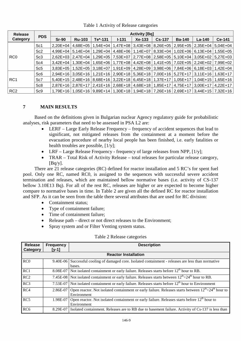
Example of the represented results is given on Table 1.
146-9
Table 1 Activity of Release categories
Release Category PDS
Activity [Bq] Sr-90 Ru-103 Te*-131 I-131 Xe-133 Cs-137 Ba-140 La-140 Ce-141
RC0
Sc1 2,20E+04 4,68E+05 1,54E+04 1,47E+08 3,43E+08 8,26E+05 2,95E+05 2,35E+04 5,04E+04 Sc2 4,99E+04 5,14E+04 1,29E+04 4,48E+06 1,14E+07 8,33E+04 1,02E+06 6,13E+04 1,55E+05 Sc3 2,62E+03 2,47E+04 1,29E+05 7,53E+07 2,77E+08 2,58E+05 5,10E+04 3,05E+02 5,27E+03 Sc4 3,42E+04 1,30E+04 1,65E+06 1,77E+08 4,42E+08 1,41E+05 7,02E+05 2,24E+02 7,99E+02 Sc5 3,83E+05 1,52E+05 3,18E+07 1,91E+09 4,28E+09 3,98E+06 7,84E+06 6,18E+03 1,42E+04
RC1 Sc6 2,94E+16 3,05E+16 1,21E+16 2,90E+18 5,36E+18 7,00E+16 5,27E+17 3,11E+16 1,63E+17 Sc7 5,40E+15 2,48E+16 8,68E+16 3,22E+18 6,45E+18 1,37E+17 1,05E+17 1,04E+15 1,65E+16 Sc8 2,87E+16 2,87E+17 2,41E+16 2,68E+18 4,68E+18 1,85E+17 4,75E+17 3,00E+17 4,22E+17
RC2 Sc9 1,79E+16 1,05E+16 9,89E+14 1,30E+18 1,94E+18 7,26E+16 2,69E+17 3,44E+15 7,32E+16
7 MAIN RESULTS
Based on the definitions given in Bulgarian nuclear Agency regulatory guide for probabilistic analyses, risk parameters that need to be assessed in PSA L2 are:
• LERF – Large Early Release Frequency – frequency of accident sequences that lead to significant, not mitigated releases from the containment at a moment before the evacuation procedure of nearby local people has been finished, i.e. early fatalities or health troubles are possible, [1/y];
• LRF – Large Release Frequency - frequency of large releases from NPP, [1/y]; • TRAR – Total Risk of Activity Release – total releases for particular release category,
[Bq/y]. There are 21 release categories (RC) defined for reactor installation and 5 RC’s for spent fuel
pool. Only one RC, named RC0, is assigned to the sequences with successful severe accident termination and releases, which are maintained bellow normative bases (i.e. activity of CS-137 bellow 3.10E13 Bq). For all of the rest RC, releases are higher or are expected to become higher compare to normative bases in time. In Table 2 are given all the defined RC for reactor installation and SFP. As it can be seen from the table there several attributes that are used for RC division:
• Containment status; • Type of containment failure; • Time of containment failure; • Release path – direct or not direct releases to the Environment; • Spray system and or Filter Venting system status.
Table 2 Release categories
Release Category
Frequency [y-1]
Description
Reactor Installation RC0 9.40E-06 Successful cooling of damaged core. Isolated containment - releases are less than normative
bases. RC1 8.08E-07 Not isolated containment or early failure. Releases starts before 12th hour to RB. RC2 7.45E-08 Not isolated containment or early failure. Releases starts between 12th÷24th hour to RB. RC3 7.53E-07 Not isolated containment or early failure. Releases starts before 12th hour to Environment RC4 2.86E-07 Open reactor. Not isolated containment or early failure. Releases starts between 12th÷24th hour to
Environment RC5 1.98E-07 Open reactor. Not isolated containment or early failure. Releases starts before 12th hour to
Environment RC6 8.29E-07 Isolated containment. Releases are to RB due to basement failure. Activity of Cs-137 is less than

146-10
Release Category
Frequency [y-1]
Description
3.0Е13 Bq up to the end of calculation RC7 6.13E-08 Isolated containment. Sprays are in operation. Late containment failure due to hydrogen burning.
Releases starts between 24th÷48th hour to Environment RC8 2.90E-11 Isolated containment. Sprays are in operation. Containment failure after vessel breach due to
hydrogen burning, HPME or ex-vessel steam explosion. Late containment failure due to hydrogen burning. Releases starts between 12th÷24th hour to Environment
RC9 4.02E-09 Isolated containment. Sprays and Filter system are failed. Containment failure after vessel breach due to hydrogen burning, HPME or ex-vessel steam explosion. Late containment failure due to hydrogen burning. Releases starts between 12th÷24th hour to Environment.
RC10 8.65E-08 Isolated containment. Sprays and Filter system are failed. Late containment failure due to basement failure. Releases starts between 24th÷48th hour to RB.
RC11 8.13E-08 Isolated containment. Sprays are failed. Containment failure after vessel breach due to hydrogen burning, overpressure or Filter system isolation failure. Releases starts between 24th÷48th hour to Environment.
RC12 3.35E-06 Isolated containment. Sprays are failed. Containment failure after vessel breach due to hydrogen burning, overpressure or Filter system isolation failure. Releases starts after 48th hour to Environment.
RC13 4.22E-06 Isolated containment. Sprays are failed. Containment failure after vessel breach due to hydrogen burning, overpressure or Filter system isolation failure. Releases starts after 48th hour to RB.
RC14 3.53E-06 Open reactor. Isolated containment. Sprays are failed. Late containment failure due to basement failure. Releases starts after 48th hour to RB. Activity of Cs-137 is less than 3.0Е13 Bq up to the end of calculation.
RC15 4.06E-06 Open reactor. Isolated containment. Sprays are failed. . Late containment failure due to basement failure. Releases starts after 48th hour to RB. Activity of Cs-137 is higher than 3.0Е13 Bq.
RC16 4.32E-06 Isolated containment. Sprays are failed. Filter system is in operation. Releases from Filter system are less than normative bases. In late phase, after 48th hour, containment failed due to basement failure and releases to the RB goes beyond normative bases.
RC17 1.73E-06 Containment bypass. IE is Primary to Secondary LOCA. SDA is stuck open. Early releases to the Environment.
RC18 2.64E-07 Containment bypass. IE is Primary to Secondary LOCA. SDA operates in cycling mode. Early releases to the Environment.
RC19 1.93E-07 Containment bypass. IE is Interface LOCA. Early releases to the RB. RC20 1.98E-08 Containment bypass due to HT SGTR. Releases to the Environment.
Spent Fuel Pool SFP-RC0 4.14E-08 Successful cooling of damaged core. Isolated containment - releases are less than normative
bases. SFP-RC1 1.83E-06 Isolated containment. Late containment failure due to overpressure. Releases to the Environment
starts after 9 days from the accident beginning. SFP-RC2 3.21E-07 Not isolated containment or early failure. Releases starts between 12th÷24th hour to the
Environment. SFP-RC3 5.37E-07 Not isolated containment or early failure. Releases starts after 72th hour to the Environment. SFP-RC4 1.64E-09 Isolated containment. Late containment failure due to basement failure. Releases to the RB starts
after 10 days from the accident beginning. On Figure 11 are shown distributions for Release categories (excluding RC0) for all modes of
Reactor Installation (RI), closed and open reactor. The results states that dominating categories are RC13÷RC16, which actually represents
accident sequences with basement failure in the late phase of the accident progression. The common characteristic between these 3 categories is that releases onset after 48-th hour from the emergency evacuation start point. The other significant dominant category is again a late failure (after 48-th hour) of the containment (RC12) but the failure is caused by containment overpressure or Filter venting system isolation failure. The results for open and closed reactor confirm already made conclusions.

146-11
Reactor Installation – all modes
Closed reactor Open Reactor
Figure 11: Release Category Distribution for Reactor Installation
Looking at the aspects of the accident for SFP, one can conclude that here the differences between early and late releases are even more outlined compare to RI. As it is shown on Figure 12, the only one RC that can be considered as early release (release onset starts between 12th÷24th hours ) is RC2, which has only 12 % of contribution.
Figure 12: Release Category Distribution for SFP
The risk from releases is divided into two main groups, based on the interpretations for LERF and LRF given in the above. The main problem of assigning of different categories to LERF or LRF is the time after the emergency evacuation start point. The emergency evacuation start point is defined very clearly in the KNPP Emergency plan based on the IE, safety systems state and core state (e.g. temperature at core exit is above 650 ͦC). Unfortunately, there are no normative bases or regulations or any other source of information that says what is the time duration of the evacuation procedure. Therefore, three different time intervals are assumed based on engineering judgment and other countries experiences. For LERF and respectively for LRF, the three time thresholds are 12-th
146-12
hour, 24-th hour and 48-th hour. In that sense based on different groupings of RC’s, three different numbers for LERF and LRF has been obtained:
• The evacuation finishes before 12-th hour – LERF is 3,92E-06 [1/y] and LRF is 2,05E-05 [1/y];
• The evacuation finishes before 24-th hour – LERF is 4,43E-06 [1/y] and LRF is 2,01E-05 [1/y];
• The evacuation finishes before 48-th hour – LERF is 4,67E-06 [1/y] and LRF is 1,98E-05 [1/y].
Apparently, the results shows that the assumptions for different evacuation duration do not impact significantly the final results for LERF and LRF parameters. Moreover, LERF in all three cases is significantly less than target criterion, which is 1.0E-05 [1/y].
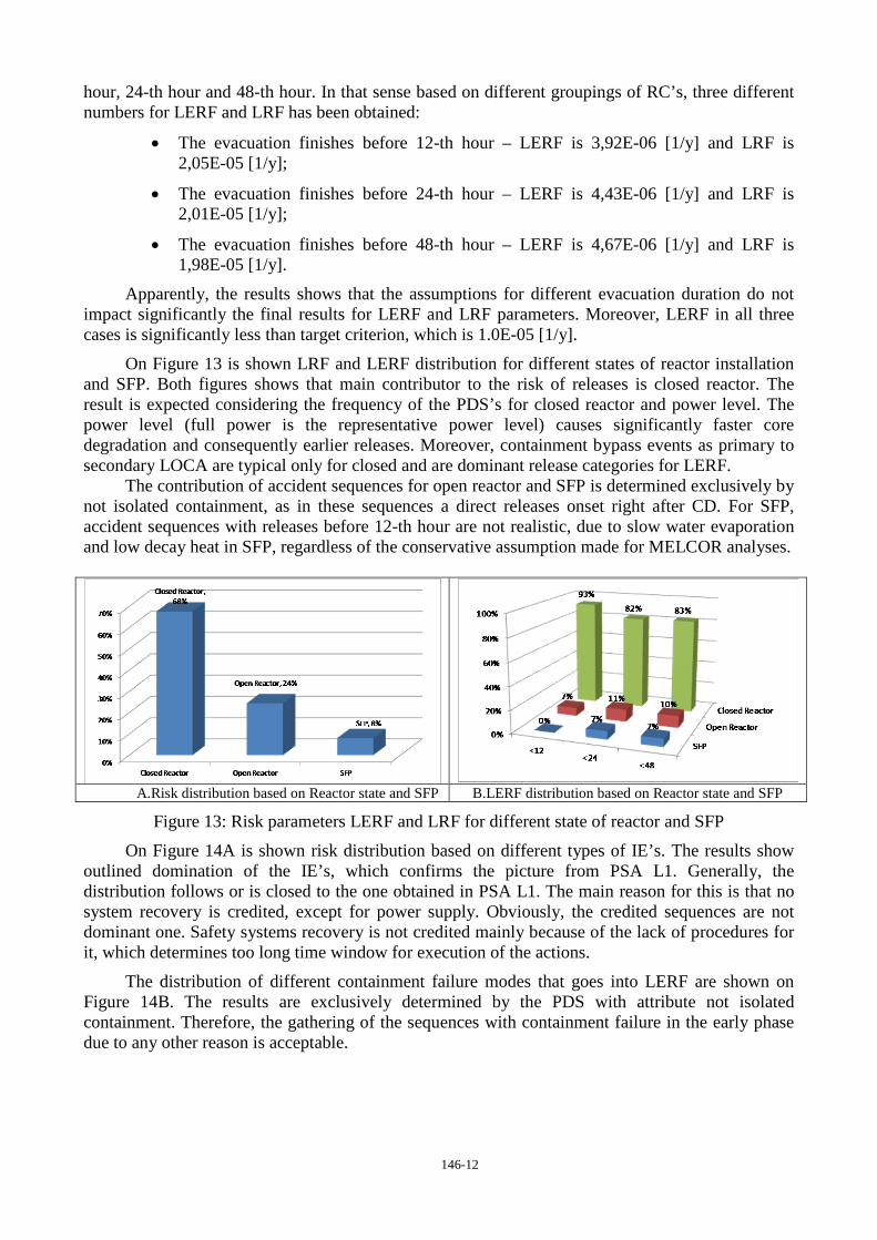
On Figure 13 is shown LRF and LERF distribution for different states of reactor installation and SFP. Both figures shows that main contributor to the risk of releases is closed reactor. The result is expected considering the frequency of the PDS’s for closed reactor and power level. The power level (full power is the representative power level) causes significantly faster core degradation and consequently earlier releases. Moreover, containment bypass events as primary to secondary LOCA are typical only for closed and are dominant release categories for LERF.
The contribution of accident sequences for open reactor and SFP is determined exclusively by not isolated containment, as in these sequences a direct releases onset right after CD. For SFP, accident sequences with releases before 12-th hour are not realistic, due to slow water evaporation and low decay heat in SFP, regardless of the conservative assumption made for MELCOR analyses.
A.Risk distribution based on Reactor state and SFP B.LERF distribution based on Reactor state and SFP
Figure 13: Risk parameters LERF and LRF for different state of reactor and SFP
On Figure 14A is shown risk distribution based on different types of IE’s. The results show outlined domination of the IE’s, which confirms the picture from PSA L1. Generally, the distribution follows or is closed to the one obtained in PSA L1. The main reason for this is that no system recovery is credited, except for power supply. Obviously, the credited sequences are not dominant one. Safety systems recovery is not credited mainly because of the lack of procedures for it, which determines too long time window for execution of the actions.
The distribution of different containment failure modes that goes into LERF are shown on Figure 14B. The results are exclusively determined by the PDS with attribute not isolated containment. Therefore, the gathering of the sequences with containment failure in the early phase due to any other reason is acceptable.

146-13
A.Risk distribution based on IE group B. Containment failure distribution based on phenomena types
Figure 14: Risk distribution based on type of IE and LERF based on containment failure mode
8 CONCLUSIONS
Based on the Bulgarian regulations for existing plants (currently in operation) the target risk parameters for severe accidents are:
Art10 (3) For severe accidents, the limit of cesium-137 release in the atmosphere is 30 TBq that does not impose long-term restrictions for soil and water use in the monitored area. Combined release of other radionuclides different from cesium isotopes shall not in a long-term perspective, starting three months after the accident, provoke a greater hazard than the one identified for cesium release within the indicated limit.
Art10 (4) The frequency of a large radioactive release into the environment that requires undertaking of immediate protective measures for the population shall not exceed 1.10-6 events per NPP per year.
Since the last paragraph is considered for new plants, for the existing one as is KNPP, the requirement of interest is given in Transitional and Final Provisions:
§ 3 (3) The frequency of a large radioactive release into the environment that requires undertaking of immediate protective measures for the population shall not exceed 1.10-5 events per NPP per year.
The last risk parameter is considered as LERF in the analysis.
Comparison of the obtained values for LERF against normative requirements for existing plants shows that the current safety level of unit 5 and 6 of KNPP meets the criteria for all three estimated LERF’s. The results completely meets the international requirements for plants, which design is not performed based on the last contemporary safety standards. Therefore, one can conclude that safety level of KNPP is acceptable.
Considering the requirement given in article 10 (3), which determines the maximum allowed magnitude of releases of Cs-137, only RC0 for Reactor installation and SFP-RC0 for SFP, meet this criterion. For all other release categories, this criterion is violated. That means that the releases in these categories should be always considered as large.
Analysis of the results (main results and sensitivity analyses results) shows that:
• Major risk for radionuclide products releases to the environment in the early phase of the accident is dominated by primary to Secondary LOCA events, i.e. containment bypass;
• Major challenge to the containment integrity is basement melt through (concrete ablation). This could be explained with lack of severe accident management strategies directed to the MCCI management;

146-14
• Operator actions for containment isolation are of high significance considering the LERF. In case of guaranteed isolation the LERF is lowered twice. Note, that all these actions need to be performed before severe accident onset;
• Operator action for Primary pressure decrease lowers the risk of early containment failures with about 22 %, which shows the significance of this action;
• The HPME and DCH phenomena do not represent significant risk to the containment integrity. The main reasons for this results are lower compartments layout (lack of direct path to the upper containment volume), reactor cavity construction (closed cavity) and the high containment free volume that allows to accumulate the heat transferred from the corium to containment atmosphere;
• The in and ex-vessel steam explosion phenomena have negligible contribution to the LERF and LRF due to lack of conditions for occurrence for most of the scenarios and very low probability of containment failure in case of occurrence;
• Dynamic loads and consequent failure of the containment structure due to hydrogen and/or carbon monoxide burning are probable only in the late phase of the severe accident progression. The burning modes that are expected are flame acceleration or detonation. Note, that main source of flammable gas at this phase of the accident is MCCI phenomenon;
• Significant contribution to the SFP risk decrease would have an implementation of SAMG for SFP severe accidents. Considering the slower accident progression and available time, restoration of systems would decrease the risk several times;
• Unequal decay heat distribution of the fuel assemblies in SFP (loading of FA with high decay heat in one of the SFP pools) leads to significant decreasing of time to fuel damage and faster severe accident progression.
Based on the conclusions different corrective measures are proposed to the plant staff. For most of the proposed measures additional analyses are required.

146-15
REFERENCES
[1] Probabilistic Safety Analysis for NPP, Safety Guide, BNRA, 2010
[2] Development and Application of Level 2 Probabilistic Safety Assessment for Nuclear Power Plants, specific Safety Guide No. SSG-4, IAEA, Vienna 2010;
[3] ASAMPSA2, 2010, BEST-PRACTICES GUIDELINES FOR L2PSA DEVELOPMENT AND APPLICATIONS, Volume 2 - Best practices for the Gen II PWR, Gen II BWR L2PSAs. Extension to Gen III reactors, ASAMPSA2/WP2&3/ 2010-28
[4] U.S. NRC, REGULATORY GUIDE 1.216, CONTAINMENT STRUCTURAL INTEGRITY EVALUATION FOR INTERNAL PRESSURE LOADINGS ABOVE DESIGN BASIS PRESSURE
[5] U.S. NRC, DRAFT REGULATORY GUIDE DG -1203, CONTAINMENT PERFORMANCE FOR PRESSURE LOADS, December 2008,
[6] U.S. NRC, REGULATORY GUIDE 1.136, DESIGN LIMITS, LOADING COMBINATIONS, MATERIALS, CONSTRUCTION, AND TESTING OF CONCRETE CONTAINMENTS, December 2008
[7] Rizkalla, Sami H., Simmonds, Sydney H., MacGregor, James G., Pre-stressed Concrete Containment Model, Journal of Structural Engineering, Vol.11, No. 4, April 1984, pp.730-743
[8] International Standard Problem No.48 Containment Capacity, Synthesis Report, NEA/CSNI/R(2005)5, OECD Nuclear Energy Agency, Committee on the Safety of Nuclear Installations, France, September, 2005
[9] NUREG / CR-6906, “Containment Integrity Research at Sandia National Laboratories – An overview”, Washington DC, July 2006.