main monitor user guide - pmc-speakers.compmc-speakers.com/sites/default/files/attachments/web-main...
TRANSCRIPT

QB1-A
QB1 XBD-ABB6 XBD-A
BB6
MB3 XBD-A
MB3
Main monitor user guide MB3 XBD-AMB3-A BB6 XBD-ABB6-A QB1 XBD-AQB1-A
TM
Advanced Transmission Line

This document should not be construed as a commitment on the part of The Professional Monitor Company Limited.
The Professional Monitor Company Limited will not assume responsibility for errors that may appear in this document.
Information may be subject to change.

Warranty Certificate
Please take a few moments to complete the warranty card at the back of this
booklet (or register at www.pmc-speakers.com) as this not only records the
purchase of your loudspeakers, but also provides you with an opportunity to make
suggestions and provide feedback directly to PMC.
Product Support
For product support, accessories or servicing advice, please contact
a PMC authorised dealer. See www.pmc-speakers.com
Company Details THE PROFESSIONAL MONITOR COMPANY LIMITED HOLME COURT BIGGLESWADE BEDFORDSHIRE UK T +44 (0) 1767 686300 F +44 (0) 870 4441045 email: [email protected] web: www.pmc-speakers.com
Important
!

Our sole aim while designing loudspeakers is to recreate the true essence of an artist’s intention,
combining the maximum possible sonic resolution with solid engineering principles.
We believe that the same loudspeaker can be used throughout the entire audio chain, from
composer to studio or film stage, post-production or mastering and then, finally, the consumer. We
also think that a well designed loudspeaker should be able to excel regardless of the audio genre,
and reproduce spoken word, rock, pop, or classical music with the same precision and accuracy.
Our unswerving passion for getting designs right has made this goal possible.
Thank you for choosing PMC products. Please read this user guide and install your new main
monitors according to the advice you’ll find in the following pages.
43
44
45
46
47
48
49
50
51
52
53
54
55
56
Peter Thomas OwnerOliver Thomas Head Of Design
A message from Peter & Oliver Thomas

Congratulations - You have joined the elite
Over more than two decades PMC has
earned an unrivalled reputation for creating
the world’s finest professional loudspeakers.
Simply put, our loudspeakers provide
a reference for the very highest profile
productions and events. They are found at
every stage of the creative process, from
conception to recording and broadcast
and, of course, in the home.
Our client list reads like a who’s who of
the sonically aware, with Stevie Wonder,
Elbow, Coldplay, Brian May, Universal, EMI,
Sony, Capitol Studios, Pinewood Studios,
Dreamworks, Metropolis Studios and the BBC
among the makers of movies and music who
use our products.
Our loudspeakers were also used in
the production of Titanic, The Bourne
Supremacy, Game of Thrones, Skyfall,
Finding Dory, the Pirates of the Caribbean
franchise, and during broadcasts of the
London Olympics, 2012.
EMI
Stevie Wonder
BBCTony Bennett
Coldplay
UNIVERSAL MUSIC GROUP
elbow
Thomas Newman
Afrojack
Warner Music
Kraftwerk
Pinewood Studios
Capitol Studios
BASEMENT JAXX
ESPN
SONY
JVC Studios
PMC: the authority for quality sound.
43
44
45
46
47
48
49
50
51
52
53
54
55
56
Metropolis Studios

User guide
Contents
General usage guidelines
Introduction
Specifications – MB3, BB6 & QB1
PMC’s ATL™ – How the Advanced Transmission Line works
System description – MB3, BB6 & QB1
User EQ options
Connections
Running in
Accessories
Positioning Surround monitoring systems
Operational controls The PMC range
Service
Our meticulous care and attention Warranty online
Warranty certificate – Part 1 – your copy
Warranty certificate – Part 2 – PMC’s copy
Your comments – help us improve
Inspection certificate
Notes
43
44
45
46
47
48
49
50
51
52
53
54
55
56
43
44
45
46
47
48
49
50
51
52
53
54
55
56
43
44
45
46
47
48
49
50
51
52
53
54
55
56
43
44
45
46
47
48
49
50
51
52
53
54
55
56
43
44
45
46
47
48
49
50
51
52
53
54
55
56
43
44
45
46
47
48
49
50
51
52
53
54
55
56
43
44
45
46
47
48
49
50
51
52
53
54
55
56
43
44
45
46
47
48
49
50
51
52
53
54
55
56
43
44
45
46
47
48
49
50
51
52
53
54
55
56
43
44
45
46
47
48
49
50
51
52
53
54
55
56
43
44
45
46
47
48
49
50
51
52
53
54
55
56
43
44
45
46
47
48
49
50
51
52
53
54
55
56
43
44
45
46
47
48
49
50
51
52
53
54
55
56
43
44
45
46
47
48
49
50
51
52
53
54
55
56
43
44
45
46
47
48
49
50
51
52
53
54
55
56
43
44
45
46
47
48
49
50
51
52
53
54
55
56
43
44
45
46
47
48
49
50
51
52
53
54
55
56
43
44
45
46
47
48
49
50
51
52
53
54
55
56
43
44
45
46
47
48
49
50
51
52
53
54
55
56
43
44
45
46
47
48
49
50
51
52
53
54
55
56
43
44
45
46
47
48
49
50
51
52
53
54
55
56

Read these instructions and keep them in a safe place for future reference.
Heed all electrical safety warnings, including any on the loudspeakers themselves.
Do not use the loudspeakers near water.
Sufficient clearances and free flow of air are required around the control1200 and the power2400.
Do not attempt to open the equipment. There are no user serviceable parts inside.
Please refer all servicing to PMC authorised personnel. Servicing is required when the apparatus is damaged, exposed to moisture, or exhibits a distinct or sudden change of operation or audio performance.
Unplug this product from both signal source and power during electrical storms or when unused for extended periods of time.
Packaging material can pose danger to the young and vulnerable. Ensure these items are stored or disposed of safely.
PMC main monitors can produce sound pressure levels in excess of 120dB. Long-term exposure to high levels of sound has the potential to cause hearing damage. Use care when adjusting the system volume to ensure sound pressure levels remain within safe and comfortable limits.
PMC main monitors contain very powerful magnets and therefore may have a detrimental effect on nearby magnetically-sensitive items, such as CRT (tube-style) televisions or monitors, and media such as floppy discs, cassettes and videotapes.
The cabinet should only be cleaned with a dry, lint-free, cloth. Do not use solvents, abrasives, waxes or liquids as they may be detrimental to the finish.
The control1200 and the power2400 can produce hazardously high outputs, installation must be carried out by trained staff.
PMC has made efforts to provide accurate installation information and good quality fixings. However, PMC will not be held responsible or liable for injuries or property damage (direct, indirect or consequential) arising out of use or inability to use this product safely and properly.
This product may contain nuts.
General usage guidelines
43
44
45
46
47
48
49
50
51
52
53
54
55
56
43
44
45
46
47
48
49
50
51
52
53
54
55
56
43
44
45
46
47
48
49
50
51
52
53
54
55
56
43
44
45
46
47
48
49
50
51
52
53
54
55
56
43
44
45
46
47
48
49
50
51
52
53
54
55
56
43
44
45
46
47
48
49
50
51
52
53
54
55
56
43
44
45
46
47
48
49
50
51
52
53
54
55
56
43
44
45
46
47
48
49
50
51
52
53
54
55
56
43
44
45
46
47
48
49
50
51
52
53
54
55
56
43
44
45
46
47
48
49
50
51
52
53
54
55
5643
44
45
46
47
48
49
50
51
52
53
54
55
56
43
44
45
46
47
48
49
50
51
52
53
54
55
56
43
44
45
46
47
48
49
50
51
52
53
54
55
56
43
44
45
46
47
48
49
50
51
52
53
54
55
56
43
44
45
46
47
48
49
50
51
52
53
54
55
56
IntroductionTogether, our MB, BB and QB reference monitor series comprise the world-class PMC Main Monitor
range — a trio of fully active three-way studio designs combining custom PMC-designed drivers,
Class-D electronics, carefully engineered DSP control and the company’s proprietary ATL™ bass-
loading technology to deliver the ultimate in power and precision, with forensic levels of detail.
The range’s combination of its highly damped, low-resonance cabinets and unique ATL™ technology
ensures that unwanted mid-range energy is absorbed, while bass output is substantially extended
whilst having insignificant harmonic distortion. Every element of the design is carefully considered to
maximise transparency and resolution, all the way down to the absorbent material on the front baffles,
which reduce reflections for improved dispersion and definition, allowing instruments and vocals to be
reproduced more vividly and with greater presence and clarity than ever before.
The drivers are bespoke PMC creations, with the HF and mid-range drivers common to all three designs.
The 34mm soft-dome tweeter is the most sensitive direct radiating tweeter available anywhere, with a
proven track record for delivering neutral, uncoloured high-resolution audio.
The perforated acoustic lens extends the response beyond 25kHz and controls dispersion to ensure
perfect integration with the highly efficient, low-distortion 75mm soft-dome mid-range driver through
the crossover region.
The MB and BB series feature extremely powerful, custom-tailored Radial bass units, renowned for their
dynamic response and thermal efficiency — a 12-inch driver on the MB3, a 15-inch on the BB6 — while
the QB1-A features a quartet of individually matched PMC 10-inch piston drivers for the last word in
accurate, near-instantaneous transient response. Perfectly integrated with the ATL™, these deliver
the clean, extended bass for which PMC is renowned, accurate all the way down to 20Hz (17Hz on
the BB6).
The 19-inch rackmount, externally housed electronics provide cutting-edge, ultra-low distortion
Class-D power amplification, with a DSP-based crossover providing perfect driver optimisation and
integration, as well as a non-invasive protective limiting system.
Remote control facilities enable the user to calibrate the system level and equalisation, as well as
select between analogue and AES3 digital inputs, and recall personal equalisation presets.
All of PMC’s Main Monitors are available as XBD-A versions, which feature a second bass driver in a
separate powered cabinet, increasing the available LF headroom of the system by 3dB. The XBD-
Active cabinet can also be used as a stand-alone subwoofer or LFE monitor if desired.
43
44
45
46
47
48
49
50
51
52
53
54
55
56
MB3-A
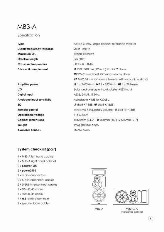
MB3-A MB3-C-A(Horizontal centre)
43
44
45
46
47
48
49
50
51
52
53
54
55
5643
44
45
46
47
48
49
50
51
52
53
54
55
56
Specification
Type Active 3-way, single-cabinet reference monitor
Usable frequency response 20Hz - 25kHz
Maximum SPL 126dB @1metre
Effective length 3m (10ft)
Crossover frequencies 380Hz & 3.8kHz
Drive unit complement LF PMC 310mm (12-inch) Radial™ driver
MF PMC hand-built 75mm soft-dome driver
HF PMC 34mm soft-dome tweeter with acoustic radiator
Amplifier power LF 1 x 2400Wrms MF 1 x 550Wrms HF 1 x 275Wrms
I/O Balanced analogue input, digital AES3 input
Digital input AES3, 24-bit, 192kHz
Analogue input sensitivity Adjustable +4dB to +20dBu
EQ LF shelf +/-8dB, HF shelf +/-8dB
Remote control Wired via RJ45, rotary volume -48.5dB to +15dB
Operational voltage 115V/230V
Cabinet dimensions H 870mm (34.2”) W 380mm (15”) D 535mm (21”)
Weight 49kg (108lbs) each
Available finishes Studio black
System checklist (pair)
1 x MB3-A left hand cabinet
1 x MB3-A right hand cabinet
2 x control1200
2 x power2400
2 x mains connectors
2 x XLR interconnect cables
2 x D-SUB interconnect cables
1 x 20m RJ45 cable
1 x 10m RJ45 cable
1 x rc2 remote controller
2 x speaker loom cables
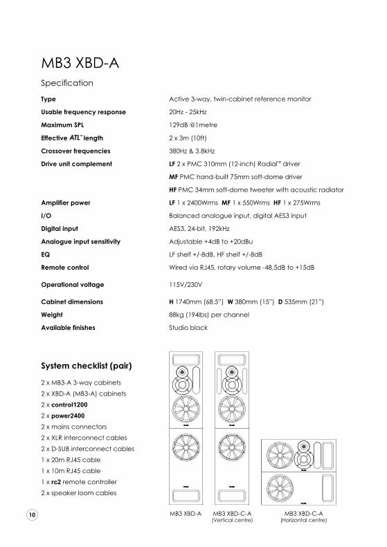
Specification Type Active 3-way, twin-cabinet reference monitor
Usable frequency response 20Hz - 25kHz
Maximum SPL 129dB @1metre
Effective TM
Advanced Transmission Line
length 2 x 3m (10ft)
Crossover frequencies 380Hz & 3.8kHz
Drive unit complement LF 2 x PMC 310mm (12-inch) Radial™ driver
MF PMC hand-built 75mm soft-dome driver
HF PMC 34mm soft-dome tweeter with acoustic radiator
Amplifier power LF 1 x 2400Wrms MF 1 x 550Wrms HF 1 x 275Wrms
I/O Balanced analogue input, digital AES3 input
Digital input AES3, 24-bit, 192kHz
Analogue input sensitivity Adjustable +4dB to +20dBu
EQ LF shelf +/-8dB, HF shelf +/-8dB
Remote control Wired via RJ45, rotary volume -48.5dB to +15dB
Operational voltage 115V/230V
Cabinet dimensions H 1740mm (68.5”) W 380mm (15”) D 535mm (21”)
Weight 88kg (194lbs) per channel
Available finishes Studio black
System checklist (pair)
2 x MB3-A 3-way cabinets
2 x XBD-A (MB3-A) cabinets
2 x control1200
2 x power2400
2 x mains connectors
2 x XLR interconnect cables
2 x D-SUB interconnect cables
1 x 20m RJ45 cable
1 x 10m RJ45 cable
1 x rc2 remote controller
2 x speaker loom cables
MB3 XBD-A
MB3 XBD-A MB3 XBD-C-A(Vertical centre)
MB3 XBD-C-A(Horizontal centre)
43
44
45
46
47
48
49
50
51
52
53
54
55
56

Specification Type Active 3-way, single-cabinet reference monitor
Usable frequency response 17Hz - 25kHz
Maximum SPL 128dB @1metre
Effective TM
Advanced Transmission Line
length 4m (13ft)
Crossover frequencies 380Hz & 3.8kHz
Drive unit complement LF PMC 380mm (15-inch) Radial™ driver
MF PMC hand-built 75mm soft-dome driver
HF PMC 34mm soft-dome tweeter with acoustic radiator
Amplifier power LF 1 x 2400Wrms MF 1 x 550Wrms HF 1 x 275Wrms
I/O Balanced analogue input, digital AES3 input
Digital input AES3, 24-bit, 192kHz
Analogue input sensitivity Adjustable +4dB to +20dBu
EQ LF shelf +/-8dB, HF shelf +/-8dB
Remote control Wired via RJ45, rotary volume -48.5dB to +15dB
Operational voltage 115V/230V
Cabinet dimensions H 1040mm (40.9”) W 432mm (17”) D 790mm (31.1”)
Weight 73kg (161lbs) each
Available finishes Studio black System checklist (pair)
1 x BB6-A left hand cabinet
1 x BB6-A right hand cabinet
2 x control1200
2 x power2400
2 x mains connectors
2 x XLR interconnect cables
2 x D-SUB interconnect cables
1 x 20m RJ45 cable
1 x 10m RJ45 cable
1 x rc2 remote controller
2 x speaker loom cables
BB6-A
BB6 BB6-C(Horizontal centre)
43
44
45
46
47
48
49
50
51
52
53
54
55
56
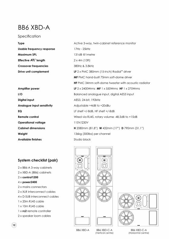
Specification Type Active 3-way, twin-cabinet reference monitor
Usable frequency response 17Hz - 25kHz
Maximum SPL 131dB @1metre
Effective TM
Advanced Transmission Line
length 2 x 4m (13ft)
Crossover frequencies 380Hz & 3.8kHz
Drive unit complement LF 2 x PMC 380mm (15-inch) Radial™ driver
MF PMC hand-built 75mm soft-dome driver
HF PMC 34mm soft-dome tweeter with acoustic radiator
Amplifier power LF 2 x 2400Wrms MF 1 x 550Wrms HF 1 x 275Wrms
I/O Balanced analogue input, digital AES3 input
Digital input AES3, 24-bit, 192kHz
Analogue input sensitivity Adjustable +4dB to +20dBu
EQ LF shelf +/-8dB, HF shelf +/-8dB
Remote control Wired via RJ45, rotary volume -48.5dB to +15dB
Operational voltage 115V/230V
Cabinet dimensions H 2080mm (81.8”) W 432mm (17”) D 790mm (31.1”)
Weight 136kg (300lbs) per channel
Available finishes Studio black System checklist (pair)
2 x BB6-A 3-way cabinets
2 x XBD-A (BB6) cabinets
2 x control1200
4 x power2400
2 x mains connectors
2 x XLR interconnect cables
4 x D-SUB interconnect cables
1 x 20m RJ45 cable
1 x 10m RJ45 cable
1 x rc2 remote controller
2 x speaker loom cables
BB6 XBD-A
BB6 XBD-A BB6 XBD-C-A(Vertical centre)
BB6 XBD-C-A(Horizontal centre)43
44
45
46
47
48
49
50
51
52
53
54
55
56

Specification
Type Active, single cabinet reference monitor
Usable frequency response 20Hz - 25kHz
Maximum SPL 132dB @1metre
Effective TM
Advanced Transmission Line
length 2.7m (8.9ft)
Crossover frequencies 380Hz & 3.8kHz
Drive unit complement LF 4 x PMC 250mm/10” piston driver
MF PMC hand-built 75mm soft dome driver
HF PMC 34mm soft dome tweeter with acoustic radiator
Amplifier power LF 2 x 4000Wrms MF 1 x 550Wrms HF 1 x 275Wrms
I/O Balanced analogue input, digital AES3 input
Digital input AES3, 192kHz 24bit
Analogue input sensitivity Adjustable +4dB to +20dBu
EQ LF shelf +/-8dB, HF shelf +/-8dB
Remote control Wired via RJ45, rotary volume -48.5dB to +15dB
Operational voltage 115V/230V
Cabinet dimensions H 820mm (32.2”) W 1092mm (42.9”) D 523mm (20.6”) (max depth)
Weight 150kg (330lbs) each
System checklist (pair)
2 x QB1-A 3-way cabinets
2 x control1200
4 x power2400
2 x mains connectors
2 x XLR interconnect cables
4 x DSUB interconnect cables
1 x 20m RJ45 cable
1 x 10m RJ45 cable
1 x rc2 remote controller
2 x speaker loom cables
QB1-A
QB1-AQB1-A
QB1 XBD-ABB6 XBD-A
BB6
MB3 XBD-A
MB3
43
44
45
46
47
48
49
50
51
52
53
54
55
56

Specification
Type Active, twin-cabinet reference monitor
Usable frequency response 20Hz - 25kHz
Maximum SPL 132dB @1metre
Effective TM
Advanced Transmission Line
length 2 x 2.7m (8.9ft)
Crossover frequencies 380Hz & 3.8kHz
Drive unit complement LF 8 x PMC 250mm/10” piston driver
MF PMC hand-built 75mm soft dome driver
HF PMC 34mm soft dome tweeter with acoustic radiator
Amplifier power LF 4 x 2400Wrms MF 1 x 550Wrms HF 1 x 275Wrms
I/O Balanced analogue input, digital AES3 input
Digital input AES3, 192kHz 24bit
Analogue input sensitivity Adjustable +4dB to +20dBu
EQ LF shelf +/-8dB, HF shelf +/-8dB
Remote control Wired via RJ45, rotary volume -48.5dB to +15dB
Operational voltage 115V/230V
Cabinet dimensions H 1640mm (64.6”) W 1092mm (42.9”) D 523mm (20.6”) (max depth)
Weight 290kg (639lbs) per channel System checklist (pair)
2 x QB1-A 3-way cabinets
2 x XBD-A (QB1-A) cabinets
2 x control1200
8 x power2400
2 x mains connectors
4 x XLR interconnect cables
8 x DSUB interconnect cables
1 x 20m RJ45 cable
1 x 10m RJ45 cable
1 x rc2 remote controller
2 x speaker loom cables
QB1 XBD-A
QB1 XBD-A
QB1-A
QB1 XBD-ABB6 XBD-A
BB6
MB3 XBD-A
MB3
43
44
45
46
47
48
49
50
51
52
53
54
55
56

characteristically transparent midrange, fast,
attacking bass, and outstanding clarity.
A further advantage is greater bass extension
and loudness than a ported or sealed
design of a similar size, even if similar drivers
were used. Moreover, the very consistent
bass driver loading brings the welcome
benefit that the frequency response remains
consistent regardless of listening level, and
analytical auditioning can be conducted
without the need for high replay volumes to
achieve optimal bass response – a unique
and very valuable characteristic.
PMC’s unique ATL™ (Advanced
Transmission Line) enclosures have taken
loudspeaker design to the highest level,
using sophisticated cabinet construction,
proprietary drive units, and patented
absorption materials and techniques. The
benefits are enormous compared to the
relatively simple sealed and ported designs
currently available elsewhere.
PMC’s innovative approach places the bass
driver near one end of a long tunnel (the
Advanced Transmission Line). This tunnel
is heavily damped with acoustic material
specified carefully to absorb the upper bass
and higher frequencies radiating from the
rear of the bass driver. The lowest frequencies
are allowed to pass down the line and
emerge from the large vent in the same
polarity as the driver’s frontal radiation,
the vent acting essentially as a second bass
driver.
An important benefit of the ATL™ approach
is that the air pressure inside the cabinet,
loading the bass driver, is maintained.
This helps to control the driver over a wide
frequency range and significantly reduces
LF distortion. Consequently, the upper bass
and midrange detail is not masked by
harmonic distortion and the result is PMC’s
Advanced Transmission Line:How it works
‘No other bass loading technology provides such resolution and tonal accuracy at all volume levels’
BB6-A
43
44
45
46
47
48
49
50
51
52
53
54
55
56

System description – MB3, BB6 & QB1
The electronic heart of PMC’s main monitors
is a powerful DSP stage which operates at a
fixed sample rate of 192kHz. The balanced
analogue line input level is conditioned by a
low-noise gain stage prior to A-D conversion,
to optimise the signal-noise ratio. The
converter is a very high quality multi-bit delta-
sigma device, producing a 24 bit, 192kHz
output. The AES3 digital input is sample rate
converted to 192kHz.
The DSP stage provides the overall system
level control, 24dB/octave precision
crossovers, and both driver optimisation and
protection. The sophisticated digital signal
processing enables perfect matching between
the three drivers’ responses and roll-off rates,
optimising the contribution of each driver,
minimising distortion, and providing a flatter and
more natural balance over the widest possible
listening area.
The output signals from the DSP system are
converted back to analogue to feed three
separate Class-D power amplifiers and
their respective drivers. The amplifier design
ensures that driver impedance variations with
frequency are fully compensated to maintain a
uniform frequency response.
43
44
45
46
47
48
49
50
51
52
53
54
55
56
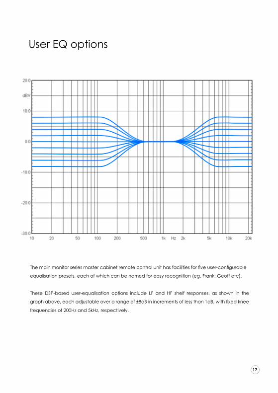
User EQ options
The main monitor series master cabinet remote control unit has facilities for five user-configurable
equalisation presets, each of which can be named for easy recognition (eg. Frank, Geoff etc).
These DSP-based user-equalisation options include LF and HF shelf responses, as shown in the
graph above, each adjustable over a range of ±8dB in increments of less than 1dB, with fixed knee
frequencies of 200Hz and 5kHz, respectively.
43
44
45
46
47
48
49
50
51
52
53
54
55
56

Connections
!
!
43
44
45
46
47
48
49
50
51
52
53
54
55
56
CautionTo avoid potential damage, please ensure that the signal source is turned off before
connecting or disconnecting your active loudspeakers.
ConnectionsThe rear panels of the control1200 and power2400 carry various connectors for audio,
control and mains power.
Audio
The electronically-balanced analogue audio input and the AES3 digital input accept
3-pin male XLR connectors, wired with Pin-1 screen (ground), Pin-2 signal positive (hot),
and Pin-3 signal negative (cold). If the monitor is to be used with an unbalanced
analogue signal source pins 1 and 3 of the input XLR should be connected together
inside the male XLR plug. Thru connections are provided for signal distribution.
Power
A single IEC (C14) mains socket is provided with an integral fuse-holder for the control1200
and an IEC (C20) mains socket with a seperate fuse-holder is provided for the power2400,
both include a voltage selector (115/230VAC) and a power switch. Only change fuses
with the power cord removed completely from the control1200 or power2400. A remote
powering facility is provided via the ‘Trigger In’ terminals which accept a 4 to12V AC
or DC voltage to enable remote switch on from an external device. The Trigger Thru
terminals can be used to extend the control signal to another speaker in the system.
Remote Control
The ‘Remote In’ RJ45 socket accepts the connection from the remote control unit, while
the Thru socket is used to distribute the control signal to the next speaker in the system.
Please Note that the final loudspeaker in the chain must have the loopback connector
fitted to the RJ45 Remote Thru socket.
Note: The control1200 and power2400 units must be earthed

Audio in, digital or analog
Remote control rc2
Link to next channel control1200
MB3-Aconnections
43
44
45
46
47
48
49
50
51
52
53
54
55
56
Rear of MB3-A
Key
XLR signal cables
Speaker cables
Control cables(RJ45 or 9 pin dsub)
Audio in, digital or analog
Remote control rc2
Link to next channel control1200
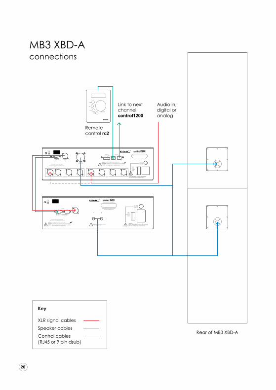
MB3 XBD-A connections
43
44
45
46
47
48
49
50
51
52
53
54
55
56
Rear of MB3 XBD-A
Key
XLR signal cables
Speaker cables
Control cables(RJ45 or 9 pin dsub)

Audio in, digital or analog
Remote control rc2
Link to next channel control1200
BB6-Aconnections
43
44
45
46
47
48
49
50
51
52
53
54
55
56
Rear of BB6-A
Key
XLR signal cables
Speaker cables
Control cables(RJ45 or 9 pin dsub)

Audio in, digital or analog
Remote control rc2
Link to next channel control1200
BB6 XBD-Aconnections
43
44
45
46
47
48
49
50
51
52
53
54
55
56
Rear of BB6-A
Key
XLR signal cables
Speaker cables
Control cables(RJ45 or 9 pin dsub)
Aud
io in
, d
igita
l or
anal
og
Rem
ote
cont
rol r
c2
Link
to n
ext
chan
nel
cont
rol1
200
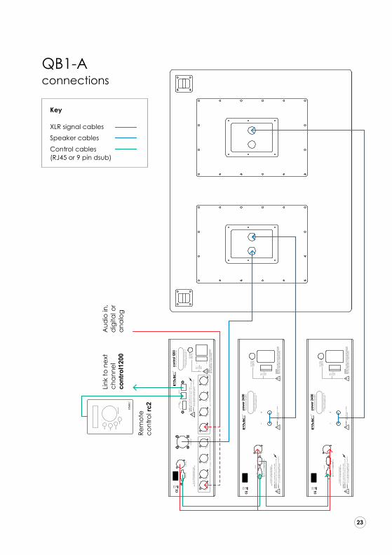
QB1-Aconnections
43
44
45
46
47
48
49
50
51
52
53
54
55
56
Key
XLR signal cables
Speaker cables
Control cables(RJ45 or 9 pin dsub)
Aud
io in
, d
igita
l or
anal
og
Rem
ote
cont
rol r
c2
XLR
cabl
e &
co
ntro
l cab
les
(9 p
in d
sub)
Link
to n
ext
chan
nel
cont
rol1
200
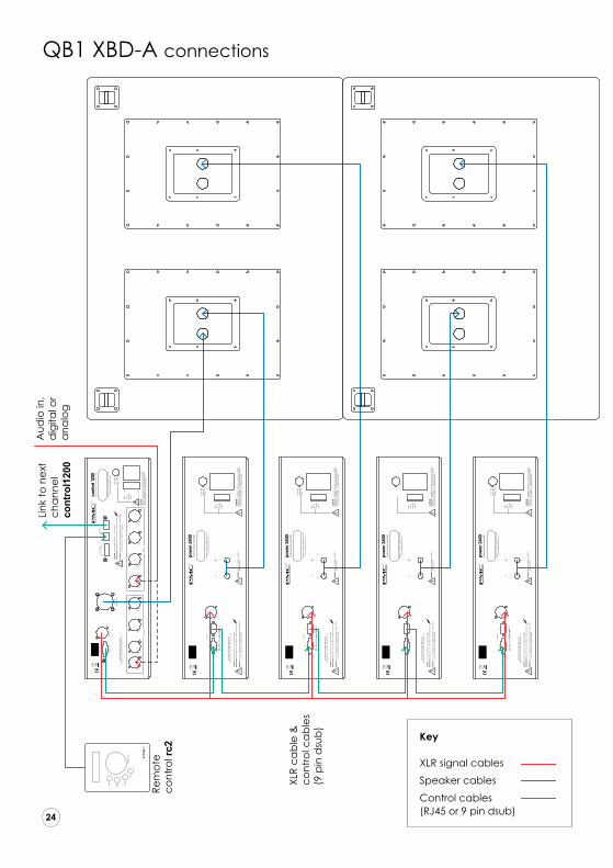
QB1 XBD-A connections
43
44
45
46
47
48
49
50
51
52
53
54
55
56
Key
XLR signal cables
Speaker cables
Control cables(RJ45 or 9 pin dsub)

Running-in
When brand new, PMC monitors take a short period of use before they reach their full
potential.
This is because the mechanical and acoustical characteristics of the bass, midrange
and treble drive units alter slightly after manufacture as the flexible elements in their
construction relax and reach their optimum compliancy. The ATL™ cabinet parameters
are critically designed to load the bass driver accurately only when it has reached its
long-term, optimal compliancy.
Consequently, during the initial running-in period of about 50 hours, the performance
of the monitor will change and improve. You will notice the bass tonality becoming
warmer, fuller and more natural, and the bass extension will increase significantly. As
the tweeter relaxes the treble tonality also sweetens and integrates perfectly with the
midrange unit, and the sound staging becomes vivid.
50+ hours to run-in
1211
10
9
8
76
5
4
3
21
43
44
45
46
47
48
49
50
51
52
53
54
55
56

Accessories
Stands
It is critical that monitor loudspeakers are positioned at the correct height and kept stable
during operation. However, the structure and materials used to support the monitor will have a
bearing on how it performs. The purpose-designed studio frame stands have been developed
with extensive listening tests in both the consumer and professional environments to optimise the
imaging, dynamics and overall tonal balance.
XBD cabinets
One or more XBDS-Active cabinets can be incorporated where greater low-frequency extension
or headroom is required, or where a dedicated effects subwoofer is appropriate. Harmonic
distortion generated by a poor quality subwoofer will mask critical mid-frequency information
from the main monitors, and also reveal the physical location of the subwoofer. However, PMC’s
unique TM
Advanced Transmission Line
cabinet design ensures extremely low levels of harmonic distortion and provides
seamless acoustical and control integration with the master cabinets.
Remote control
IB2, MB3, BB6 and QB1 monitors can be linked together and controlled by a rc2 remote control,
up to a limit of 12 channels.
43
44
45
46
47
48
49
50
51
52
53
54
55
56

Positioning
With their unique TM
Advanced Transmission Line
cabinet design, wide dispersion, ultra-low distortion, and smooth bass
roll-off, PMC loudspeakers are more forgiving of difficult room conditions and placement
constraints than conventional designs – you will be able to achieve a superb sound throughout
the room with little effort. However, we encourage you to spend some time experimenting in
your own room to achieve the very best results, remembering that small changes in location
can often influence system performance significantly. The following guidelines are suggestions
for a starting point to locate your new loudspeakers. Fine-tuning of their positioning can start
from there.
Dispersion and Toeing-in
Most loudspeakers have a relatively narrow dispersion and are designed to be aimed directly
at the listening position, as shown in the left-hand image below. However, the excellent stereo
imaging which PMC monitors are known for is due, in part, to their wide dispersion characteristic,
as shown on the right-hand image. To optimise the stereo imaging, PMC monitors should be
angled so that their axes cross about 0.5 metres (2ft) behind the listening position (as illustrated
below). Varying this toe-in angle will subtly affect the vividness of the audio soundstage.
A good music track with vivid vocals will help to determine the best position.
Conventional monitors have narrow dispersion
PMC Monitors have wide dispersion
0.5m / 20”
Line of symmetry
43
44
45
46
47
48
49
50
51
52
53
54
55
56

TIP
TIP
TIP
When initially positioning the loudspeakers, ideally they should be located at two of the three
points of an equilateral triangle, with the listener at the third. If the monitors are spaced too far
apart the stereo image will be wide but central definition will be impaired. Use a well recorded
vocal track to judge the ideal placement.
Attention should be paid to the effect of reflective surfaces such as side walls and objects in
close proximity to the loudspeakers, as excessive nearfield reflections will blur the stereo imaging
significantly and may introduce unwelcome colouration of the sound.
Place the speakers so that their front baffles are well forward of any objects placed between
them, such as computer display screens.
To prevent vertical room modes from causing boominess, do not position the speaker such that
the bass driver is at an even proportion of the room height, such as a half or a quarter.
Plinth modules can be used to raise the cabinets to help tune the bass response with respect to
the room boundaries.
43
44
45
46
47
48
49
50
51
52
53
54
55
56

TIP Ideally, the monitors should be placed more than 0.5 metres from the side and rear walls of
the room so that reinforcement and cancellation (peaks and dips) of the bass output caused
by wall reflections will be moved higher in frequency and thus less influential. This reduces the
incidence of ‘lumpy’ or ‘boomy’ bass. Small changes in position can have profound effects on
the bass response, so experiment to find the optimal position.
Bass Response
PMC’s main monitors can produce significant bass energy below the frequencies at which
they become omnidirectional. As a consequence, it is important to consider the effect of the
boundaries of the listening room when placing the monitors. The use of plinth modules can assist
in fine tuning the in-room bass response.
43
44
45
46
47
48
49
50
51
52
53
54
55
56
Line of symmetry
Bass gain
min 0.5m min 0.5m

5.1 Systems
The main monitor series monitor have been designed for
perfect multi-channel playback. The following diagrams
show the ideal layouts.
Room size and shape will often
force some loudspeakers to be placed closer or
further from the listening position than is ideal.
In such situations the time-alignment facilities of the
surround processor or monitor controller should be
employed to compensate.
The subwoofer carries the LFE signal as well as
the low bass from some, or all, of the main monitors
when bass management is being used. The subwoofer should be placed at the front of the
room, the optimal position providing the smoothest low bass without boomy or weak notes.
7.1 Systems
In a system capable of 7.1 Dolby® Digital Surround EX™
DTS® ES™ or Blu-ray™ playback, there will be two sets of surround speakers. The first pair (surround
or side channels) should be positioned at 100º, and the second set (rear or back channels) at
150º. (The front centre axis is 0º while directly to the rear of
the room is 180º).
The LFE input on the control1200 mixes the .1 effects/
LFE channel signal into the main monitors. Such is
their LF performance they are easily capable of
faithfully reproducing these frequencies
Dolby® Digital Surround EX™ is a registered trademark of Dolby® Laboratories. DTS® ES™ are registered trademarks of DTS® Inc. Blu-ray™ is a trademark of the Blu-ray™ Disc Association.
Fine tuning for perfect soundSurround monitoring systems
TIP
TIP
TIP
43
44
45
46
47
48
49
50
51
52
53
54
55
56

PMC main monitors are configured and controlled via the supplied remote control panel which has an LCD display with two rows of up to 16 characters each, plus four push buttons and a rotary control.
The top push button accesses the configuration menu, with a back button to exit. The preset button accesses the user preset facilities, and the mute button mutes the loudspeakers.
The menu displays are navigated using the rotary control wheel which has a push-button action that is used to select the currently displayed parameter.
The generic display is shown below. The lower row identi-fies the loudspeakers connected in the system (Left, Centre, Right, Left Surround, Right Surround, LFE1, LFE2), together with the current volume setting (±00.0dB in the example below). The upper row indicates the current function (Volume in this example), and the asterix symbols warn of a clipped loudspeaker channel. The rc2 remote control can be used with any IB2, MB3, BB6, QB1 configurations.
* * * * * * * V o l u m e
L C R L s R s 1 2 + 0 0 . 0 d B
1 Standby ModeStandby mode is activated either on start-up, when power-off is pressed in the main menu, or when a trigger signal is lost if the Trigger ON mode is enabled.
1.1 Trigger-OFF When the 12V trigger mode is set to OFF in the main menu (see 3.1.3) the default standby mode display will look like this (Note: the backlight will be off, and there is no sub-menu):
Z z z
Actions:
Buttons: MENU/BACK/PRESETS/MUTE/SELECT: The System turns on and the default display appears (see 2). Rotary: UP/DOWN: System turns on, and the default display appears (see 2). Clip: Can’t be sent because of standby mode. Trigger: Can’t be sent because of trigger-off mode.
Operational controls
43
44
45
46
47
48
49
50
51
52
53
54
55
56

1.2 Trigger-ON When the 12V trigger mode is set to ON in the main menu (see 3.1.3) the default standby mode display will look like this (Note: Backlight will be off, and there is no sub-menu):
A w a i t i n g T r i g g e r
Actions: Buttons: MENU: If held for more than two seconds the 12V Trigger Mode is set to OFF.
T r i g g e r M o d e O f f
This display is shown for two seconds, then the system turns ON and the default display appears (see 2). BACK/PRESETS/MUTE/SELECT: These buttons do nothing in this mode Rotary: UP/DOWN: This control does nothing in this mode. Clip: Can’t be sent, because of standby mode. Trigger: Turn on, the default display appears (see 2).
2 Default DisplayThis display appears either when there is no menu activity for more than five seconds, when the BACK but-ton is pressed in the main menu, PRESET menu, or PMC SETUP MODE menu, after a button press in standby mode, or after a trigger event (trigger-ON mode) when in standby. Provided no channels are clipping and the system is un-muted, the default display will look like this: (in this example only left and right channels are in use and volume is +15dB)
L _ R _ _ _ _ _ _ + 1 5 . 0 d B
Actions: Rotary: UP/DOWN changes volume in 0.5dB steps (minimum -48.5dB, maximum +15dB). Save value and send value to all channels. Button press: MENU: the main menu appears (see 3). BACK: If held for more than two seconds the volume locks at the current setting. The display looks like this (with +15.0 volume value as an example):
V L o c k
L C R L s R s 1 2 + 1 5 . 0 d B If the BACK button is held again for more than two seconds the volume unlocks and the display reverts to the default display. PRESET: If pressed briefly the current preset is displayed for two seconds. If held for more than two seconds, the preset menu appears (see 4). SELECT: nothing. MUTE: a mute command will be sent to all channels and the display back light will flash once per second. The Volume can not be changed during mute. (From now on this will be the default display, until the mute button is pressed in any menu). This display is shown:
A l l C h a n n e l M u t e
Clip: If any channel clips an asterix appears to identify which channels. In the example below the center, right surround, and LFE 2 speakers are clipping.
* * *L C R L s R s 1 2 + 1 5 . 0 d B
43
44
45
46
47
48
49
50
51
52
53
54
55
56
Trigger: ON mode: shut down, and show trigger on standby mode (see 1.2). OFF mode: nothing.
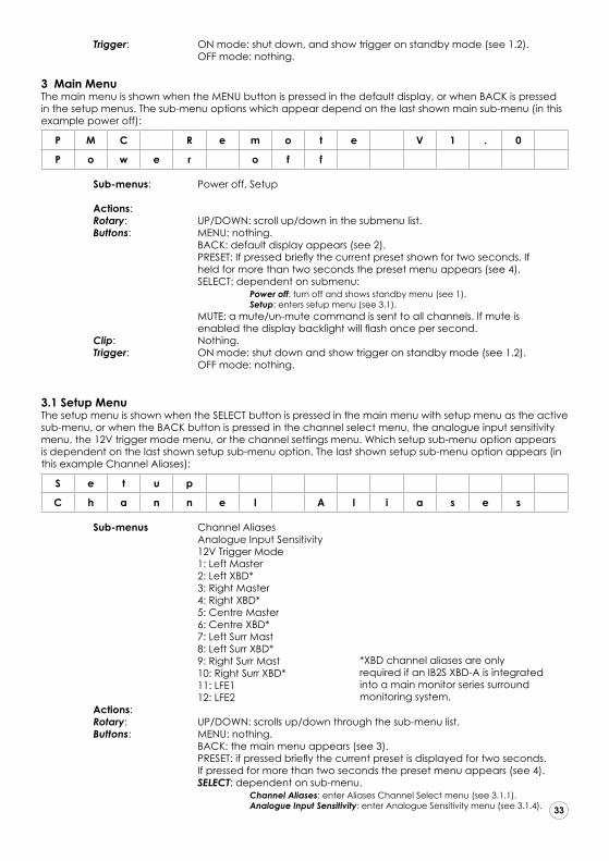
3 Main MenuThe main menu is shown when the MENU button is pressed in the default display, or when BACK is pressed in the setup menus. The sub-menu options which appear depend on the last shown main sub-menu (in this example power off):
P M C R e m o t e V 1 . 0
P o w e r o f f
Sub-menus: Power off, Setup Actions: Rotary: UP/DOWN: scroll up/down in the submenu list. Buttons: MENU: nothing. BACK: default display appears (see 2). PRESET: If pressed briefly the current preset shown for two seconds. If held for more than two seconds the preset menu appears (see 4). SELECT: dependent on submenu: Power off: turn off and shows standby menu (see 1). Setup: enters setup menu (see 3.1). MUTE: a mute/un-mute command is sent to all channels. If mute is enabled the display backlight will flash once per second. Clip: Nothing. Trigger: ON mode: shut down and show trigger on standby mode (see 1.2). OFF mode: nothing.
3.1 Setup MenuThe setup menu is shown when the SELECT button is pressed in the main menu with setup menu as the active sub-menu, or when the BACK button is pressed in the channel select menu, the analogue input sensitivity menu, the 12V trigger mode menu, or the channel settings menu. Which setup sub-menu option appears is dependent on the last shown setup sub-menu option. The last shown setup sub-menu option appears (in this example Channel Aliases):
S e t u p
C h a n n e l A l i a s e s
Sub-menus Channel Aliases Analogue Input Sensitivity 12V Trigger Mode 1: Left Master 2: Left XBD* 3: Right Master 4: Right XBD* 5: Centre Master 6: Centre XBD* 7: Left Surr Mast 8: Left Surr XBD* 9: Right Surr Mast 10: Right Surr XBD* 11: LFE1 12: LFE2 Actions: Rotary: UP/DOWN: scrolls up/down through the sub-menu list. Buttons: MENU: nothing. BACK: the main menu appears (see 3). PRESET: if pressed briefly the current preset is displayed for two seconds. If pressed for more than two seconds the preset menu appears (see 4). SELECT: dependent on sub-menu. Channel Aliases: enter Aliases Channel Select menu (see 3.1.1). Analogue Input Sensitivity: enter Analogue Sensitivity menu (see 3.1.4). 43
44
45
46
47
48
49
50
51
52
53
54
55
56
*XBD channel aliases are only required if an IB2S XBD-A is integrated into a main monitor series surround monitoring system.
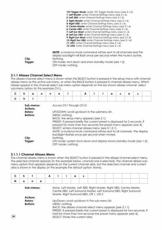
12V Trigger Mode: enter 12V Trigger Mode menu (see 3.1.3). 1: Left Master: enter Channel Settings menu (see 3.1.4). 2: Left XBD: enter Channel Settings menu (see 3.1.4). 3: Right Master: enter Channel Settings menu (see 3.1.4). 4: Right XBD: enter Channel Settings menu (see 3.1.4). 5: Centre Master: enter Channel Settings menu (see 3.1.4). 6: Centre XBD: enter Channel Settings menu (see 3.1.4). 7: Left Surr Mast: enter Channel Settings menu (see 3.1.4). 8: Left Surr XBD: enter Channel Settings menu (see 3.1.4). 9: Right Surr Mast: enter Channel Settings menu (see 3.1.4). 10: Right Surr XBD: enter Channel Settings menu (see 3.1.4). 11: LFE1: enter Channel Settings menu (see 3.1.4). 12: LFE2: enter Channel Settings menu (see 3.1.4). MUTE: a mute/un-mute command will be sent to all channels and the display backlight will flash once per second when the mute is active. Clip: Nothing. Trigger: ON mode: shut down and show standby mode (see 1.2). OFF mode: nothing.
3.1.1 Aliases Channel Select MenuThe aliases channel select menu is shown when the SELECT button is pressed in the setup menu with channel aliases menu as the active sub-menu, or when the BACK button is pressed in channel aliases menu. Which aliases appear in the channel select sub-menu option depends on the last shown aliases channel select sub-menu option (in this example Ch1).
C h a n n e l A l i a s e s
C h 1
Sub-menus: Access Ch1 through Ch12 Actions: Rotary: UP/DOWN: scroll up/down in the submenu list. Buttons: MENU: nothing. BACK: the setup menu appears (see 3.1). PRESET: if pressed briefly the current preset is displayed for 2 seconds. If pressed for more than two seconds the preset menu appears (see 4). SELECT: enters channel aliases menu (see 3.1.2.1). MUTE: a mute/un-mute command will be sent to all channels. The display backlight flashes once per second when muted. Clip: Nothing. Trigger: ON mode: system shuts down and display shows standby mode (see 1.2). OFF mode: nothing.
3.1.1.1 Channel Aliases MenuThe channel aliases menu is shown when the SELECT button is pressed in the aliases channel select menu.The selected channel appears (in the example below, channel one is selected). The channel aliases sub-menu option that appears depends on the current channel alias, but the selected channel and current alias is shown in the display (in this example the default option: None).
C h 1 A l i a s
N o n e
Sub-menus: None, Left Master, Left XBD, Right Master, Right XBD, Centre Master, Centre XBD, Left Surround Master, Left Surround XBD, Right Surround Master, Right Surround XBD, LFE 1, LFE 2 Actions: Rotary: Up/Down: scroll up/down in the sub-menu list. Buttons: MENU: nothing BACK: the aliases channel select menu appears (see 3.1.1). PRESET: If pressed briefly the current preset is displayed for two seconds. If held for more than two seconds the preset menu appears (see 4). SELECT: Stores the current alias.
43
44
45
46
47
48
49
50
51
52
53
54
55
56

MUTE: a mute/un-mute command will be sent to all channels. The display backlight will flash once per second when muted. Clip: Nothing. Trigger: ON mode: system shuts down and display shows standby mode (see 1.2) Off mode: nothing.
3.1.2 Analogue Input Sensitivity MenuThe analogue input sensitivity menu is shown when the SELECT button is pressed in the setup menu with analogue input sensitivity menu as active sub-menu. The current value appears (in this example +4.00dB). There are no sub-menus.
A n a l o g u e I n S e n s
+ 4 . 0 0 d B
Actions: Rotary: UP/DOWN: change the analogue input sensitivity in steps of 0.25dB, with a minimum value of +4dB and a maximum of +20dB. Buttons: MENU: nothing. BACK: the setup menu appears (see 3.1). PRESET: If pressed briefly the current preset is displayed for two seconds. If held for more than two seconds the preset menu appears (see 4). SELECT: saves value and sends to all channels. Setup menu appears (see 3.1). MUTE: a mute/un-mute command is sent to all channels. The display backlight flashes once per second when muted. Clip: Nothing. Trigger: ON mode: system shuts down and display shows standby mode (see 1.2). OFF mode: nothing
3.1.3 12V Trigger Mode MenuThe 12V trigger mode menu is shown when the SELECT button is pressed in the setup menu with 12V trig-ger mode menu as active sub-menu. The current setting appears (this example shows the ON mode).
1 2 V T r i g g e r M o d e
O n
Sub-menu: ON or OFF Actions: Rotary: UP/DOWN: scrolls up/down through the sub-menu list. Buttons: MENU: nothing. BACK: the setup menu appears (see 3.1) . PRESET: If pressed briefly the current preset is displayed for two seconds. If held for more than two seconds the preset menu appears (see 4). SELECT: saves setting and sends to all channels. The setup menu appears (see 3.1). Note: Trigger must be attached to first channel. MUTE: a mute/un-mute command is sent to all channels. The display backlight flashed once per second when muted. Clip: Nothing. Trigger: ON mode: system shuts down and standby mode displayed (see 1.2). OFF mode: nothing.
3.1.4 Channel Settings MenuThe Channel Settings menu is shown when the SELECT button is pressed in the setup menu with Channel Settings menu as active sub-menu, or when the back button is pressed in main source menu, main trim menu, LFE source, or LFE trim menu. The selected channel in the setup menu and selected alias appears (in this example 1, Left Master). Which Channel Settings sub-menu option appears depends on the last shown channel settings sub-menu option (in this example Main Source).
L e f t M a s t e r
M a i n S o u r c e
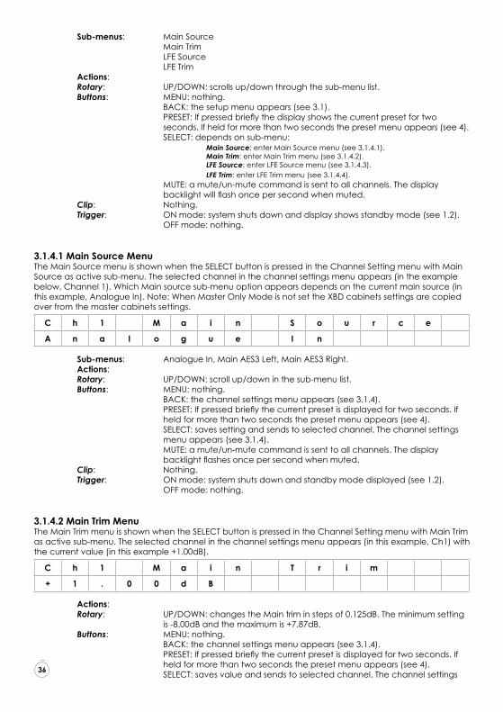
Sub-menus: Main Source Main Trim LFE Source LFE Trim Actions: Rotary: UP/DOWN: scrolls up/down through the sub-menu list. Buttons: MENU: nothing. BACK: the setup menu appears (see 3.1). PRESET: If pressed briefly the display shows the current preset for two seconds. If held for more than two seconds the preset menu appears (see 4). SELECT: depends on sub-menu: Main Source: enter Main Source menu (see 3.1.4.1). Main Trim: enter Main Trim menu (see 3.1.4.2). LFE Source: enter LFE Source menu (see 3.1.4.3). LFE Trim: enter LFE Trim menu (see 3.1.4.4). MUTE: a mute/un-mute command is sent to all channels. The display backlight will flash once per second when muted. Clip: Nothing. Trigger: ON mode: system shuts down and display shows standby mode (see 1.2). OFF mode: nothing.
3.1.4.1 Main Source MenuThe Main Source menu is shown when the SELECT button is pressed in the Channel Setting menu with Main Source as active sub-menu. The selected channel in the channel settings menu appears (in the example below, Channel 1). Which Main source sub-menu option appears depends on the current main source (in this example, Analogue In). Note: When Master Only Mode is not set the XBD cabinets settings are copied over from the master cabinets settings.
C h 1 M a i n S o u r c e
A n a l o g u e I n
Sub-menus: Analogue In, Main AES3 Left, Main AES3 Right. Actions: Rotary: UP/DOWN: scroll up/down in the sub-menu list. Buttons: MENU: nothing. BACK: the channel settings menu appears (see 3.1.4). PRESET: If pressed briefly the current preset is displayed for two seconds. If held for more than two seconds the preset menu appears (see 4). SELECT: saves setting and sends to selected channel. The channel settings menu appears (see 3.1.4). MUTE: a mute/un-mute command is sent to all channels. The display backlight flashes once per second when muted. Clip: Nothing. Trigger: ON mode: system shuts down and standby mode displayed (see 1.2). OFF mode: nothing.
3.1.4.2 Main Trim MenuThe Main Trim menu is shown when the SELECT button is pressed in the Channel Setting menu with Main Trim as active sub-menu. The selected channel in the channel settings menu appears (in this example, Ch1) with the current value (in this example +1.00dB).
C h 1 M a i n T r i m
+ 1 . 0 0 d B
Actions: Rotary: UP/DOWN: changes the Main trim in steps of 0.125dB. The minimum setting is -8.00dB and the maximum is +7.87dB. Buttons: MENU: nothing. BACK: the channel settings menu appears (see 3.1.4). PRESET: If pressed briefly the current preset is displayed for two seconds. If held for more than two seconds the preset menu appears (see 4). SELECT: saves value and sends to selected channel. The channel settings
43
44
45
46
47
48
49
50
51
52
53
54
55
56
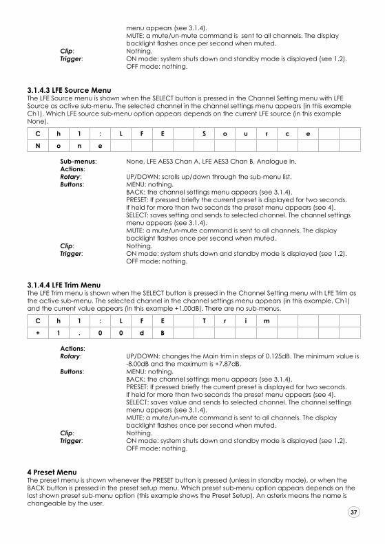
menu appears (see 3.1.4). MUTE: a mute/un-mute command is sent to all channels. The display backlight flashes once per second when muted. Clip: Nothing. Trigger: ON mode: system shuts down and standby mode is displayed (see 1.2). OFF mode: nothing.
3.1.4.3 LFE Source MenuThe LFE Source menu is shown when the SELECT button is pressed in the Channel Setting menu with LFE Source as active sub-menu. The selected channel in the channel settings menu appears (in this example Ch1). Which LFE source sub-menu option appears depends on the current LFE source (in this example None).
C h 1 : L F E S o u r c e
N o n e
Sub-menus: None, LFE AES3 Chan A, LFE AES3 Chan B, Analogue In. Actions: Rotary: UP/DOWN: scrolls up/down through the sub-menu list. Buttons: MENU: nothing. BACK: the channel settings menu appears (see 3.1.4). PRESET: If pressed briefly the current preset is displayed for two seconds. If held for more than two seconds the preset menu appears (see 4). SELECT: saves setting and sends to selected channel. The channel settings menu appears (see 3.1.4). MUTE: a mute/un-mute command is sent to all channels. The display backlight flashes once per second when muted. Clip: Nothing. Trigger: ON mode: system shuts down and standby mode is displayed (see 1.2). OFF mode: nothing.
3.1.4.4 LFE Trim MenuThe LFE Trim menu is shown when the SELECT button is pressed in the Channel Setting menu with LFE Trim as the active sub-menu. The selected channel in the channel settings menu appears (in this example, Ch1) and the current value appears (in this example +1.00dB). There are no sub-menus.
C h 1 : L F E T r i m
+ 1 . 0 0 d B
Actions: Rotary: UP/DOWN: changes the Main trim in steps of 0.125dB. The minimum value is -8.00dB and the maximum is +7.87dB. Buttons: MENU: nothing. BACK: the channel settings menu appears (see 3.1.4). PRESET: If pressed briefly the current preset is displayed for two seconds. If held for more than two seconds the preset menu appears (see 4). SELECT: saves value and sends to selected channel. The channel settings menu appears (see 3.1.4). MUTE: a mute/un-mute command is sent to all channels. The display backlight flashes once per second when muted. Clip: Nothing. Trigger: ON mode: system shuts down and standby mode is displayed (see 1.2). OFF mode: nothing.
4 Preset MenuThe preset menu is shown whenever the PRESET button is pressed (unless in standby mode), or when the BACK button is pressed in the preset setup menu. Which preset sub-menu option appears depends on the last shown preset sub-menu option (this example shows the Preset Setup). An asterix means the name is changeable by the user.
43
44
45
46
47
48
49
50
51
52
53
54
55
56

P r e s e t
P r e s e t S e t u p
Sub-menus: Preset Setup, No Preset, Preset A* to Preset E*. Actions: Rotary: UP/DOWN: scrolls up/down through the sub-menu list. Buttons: MENU: nothing. BACK: the default display appears (see 2). PRESET: If pressed briefly the current preset is displayed for two seconds. If held for more than two seconds: nothing. SELECT: depends on sub-menu: Preset Setup: enters Preset Setup menu (see 4.1). No Preset: clears preset values. Shows selected preset for two seconds and enters default display (see 2). Preset A*-E*: activates preset A-E settings. Displays selected preset for two seconds and enters default display (see 2). MUTE: a mute/un-mute command is sent to all channels. The display backlight flashes once per second when muted. Clip: Nothing. Trigger: ON mode: system shuts down and standby mode displayed (see 1.2). OFF mode: nothing.
4.1 Preset Setup MenuThe preset setup menu is shown when the SELECT button is pressed in the preset menu with preset setup as the active sub-menu, or when the BACK button is pressed in the preset aliases menu or preset settings menu. Which setup sub-menu option appears depends on the last shown preset setup sub-menu option (in this example, Preset Aliases).
P r e s e t S e t u p
P r e s e t A l i a s e s
Sub-menus: Preset Aliases, 1: Preset A* to 5: Preset E*. Actions: Rotary: UP/DOWN: scrolls up/down through the sub-menu list. Buttons: MENU: nothing. BACK: the preset menu appears (see 4). PRESET: If pressed briefly the current preset is displayed for two seconds. If held for more than two seconds the preset menu appears (see 4). SELECT: depends on sub-menu: Preset Aliases: enter Aliases Preset Select menu (see 4.1.1) Preset A*-E*: enter Preset settings menu (see 4.1.2) MUTE: a mute/un-mute command is sent to all channels. The display backlight flashes once per second when muted. Clip: Nothing. Trigger: ON mode: system shuts down and standby mode is displayed (see 1.2). OFF mode: nothing.
4.1.1 Preset Aliases Select MenuThe aliases preset select menu is shown when the SELECT button is pressed in the preset setup menu with aliases preset select as active sub-menu. Which aliases preset select sub-menu option appears depends on the last shown aliases preset select sub-menu option (in this example, 1).
P r e s e t A l i a s e s
1 : P r e s e t A
Sub-menus: 1:Preset A* to 5: Preset E* Actions: Rotary: UP/DOWN: scrolls up/down through the sub-menu list. Buttons: MENU: nothing. BACK: the preset setup menu appears (see 4). PRESET: If pressed briefly the current preset is displayed for two seconds.
43
44
45
46
47
48
49
50
51
52
53
54
55
56

If held for more than two seconds the preset menu appears (see 4). SELECT: depends on sub-menu. MUTE: a mute/un-mute command is sent to all channels. The display backlight flashed once per second when muted. Clip: Nothing. Trigger: ON mode: system shuts down and standby mode displayed (see 1.2). OFF mode: nothing.
4.1.1.1 Preset Aliases MenuThe preset aliases menu is shown when the SELECT button is pressed in the preset setup menu. The selected preset is shown (in this example 1). Which alias appears depends on the last stored alias.
P r e s e t 1 A l i a s
P r e s e t A
Sub-menus: A to Z. Actions: Rotary: If no place selected: UP/DOWN scrolls between characters, left to right. If place selected, UP/DOWN scrolls through the alphabet. Buttons: MENU: nothing. BACK: the aliases preset select menu appears (see 4.1.1). PRESET: if pressed briefly the current preset is displayed for two seconds. If held for more than two seconds the preset menu appears (see 4). SELECT: When no character us selected this highlights the current position to change character. The UP/DOWN rotary function can then be used to scroll through the alphabet. Selecting a character stores the current character. MUTE: a mute/un-mute command is sent to all channels. The display backlight flashes once per second when muted. Clip: Nothing. Trigger: ON mode: system shuts down and standby mode displayed (see 1.2). OFF mode: nothing.
4.1.2 Preset Settings MenuThe preset settings menu is shown when the SELECT button is pressed in the preset setup menu with one of the five presets as active sub-menu, or when the BACK button is pressed in the preset Front or Rear LF or HF Shelf menus, or the master only mode menu. Which preset settings sub-menu option appears depends on the last shown preset settings sub-menu option (in this example Front LF Shelf).
P r e s e t S e t t i n g s
F r o n t L F S h e l f Sub-menus: Front LF Shelf, Front HF Shelf, Rear LF Shelf, Rear HF Shelf, Master Only Mode. Actions: Rotary: UP/DOWN: scrolls up/down through the sub-menu list. Buttons: MENU: nothing. BACK: the preset setup menu appears (see 4). PRESET: if pressed briefly the current preset is displayed for two seconds. If held for more than two seconds the preset menu appears (see 4). SELECT: depends on sub-menu: Front LF Shelf: enter Front LF Shelf menu. Front HF Shelf: enter Front HF Shelf menu. Rear LF Shelf: enter Rear HF Shelf menu. Rear HF Shelf: enter Rear HF Shelf menu. MUTE: a mute/un-mute command is sent to all channels. The display backlight flashes once per second when muted. Clip: Nothing. Trigger: ON mode: system shuts down and standby mode displayed (see 1.2). OFF mode: nothing.
43
44
45
46
47
48
49
50
51
52
53
54
55
56
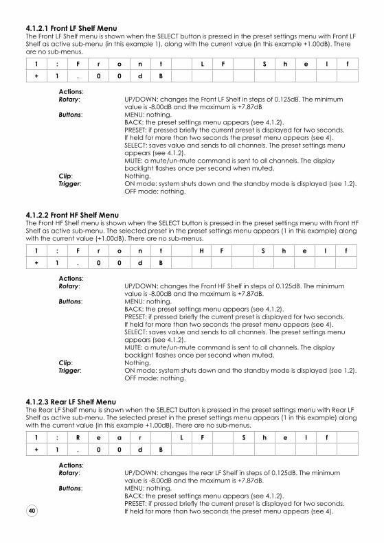
4.1.2.1 Front LF Shelf MenuThe Front LF Shelf menu is shown when the SELECT button is pressed in the preset settings menu with Front LF Shelf as active sub-menu (in this example 1), along with the current value (in this example +1.00dB). There are no sub-menus.
1 : F r o n t L F S h e l f
+ 1 . 0 0 d B
Actions: Rotary: UP/DOWN: changes the Front LF Shelf in steps of 0.125dB. The minimum value is -8.00dB and the maximum is +7.87dB Buttons: MENU: nothing. BACK: the preset settings menu appears (see 4.1.2). PRESET: if pressed briefly the current preset is displayed for two seconds. If held for more than two seconds the preset menu appears (see 4). SELECT: saves value and sends to all channels. The preset settings menu appears (see 4.1.2). MUTE: a mute/un-mute command is sent to all channels. The display backlight flashes once per second when muted. Clip: Nothing. Trigger: ON mode: system shuts down and the standby mode is displayed (see 1.2). OFF mode: nothing.
4.1.2.2 Front HF Shelf MenuThe Front HF Shelf menu is shown when the SELECT button is pressed in the preset settings menu with Front HF Shelf as active sub-menu. The selected preset in the preset settings menu appears (1 in this example) along with the current value (+1.00dB). There are no sub-menus.
1 : F r o n t H F S h e l f
+ 1 . 0 0 d B Actions: Rotary: UP/DOWN: changes the Front HF Shelf in steps of 0.125dB. The minimum value is -8.00dB and the maximum is +7.87dB. Buttons: MENU: nothing. BACK: the preset settings menu appears (see 4.1.2). PRESET: if pressed briefly the current preset is displayed for two seconds. If held for more than two seconds the preset menu appears (see 4). SELECT: saves value and sends to all channels. The preset settings menu appears (see 4.1.2). MUTE: a mute/un-mute command is sent to all channels. The display backlight flashes once per second when muted. Clip: Nothing. Trigger: ON mode: system shuts down and the standby mode is displayed (see 1.2). OFF mode: nothing.
4.1.2.3 Rear LF Shelf MenuThe Rear LF Shelf menu is shown when the SELECT button is pressed in the preset settings menu with Rear LF Shelf as active sub-menu. The selected preset in the preset settings menu appears (1 in this example) along with the current value (in this example +1.00dB). There are no sub-menus.
1 : R e a r L F S h e l f
+ 1 . 0 0 d B
Actions: Rotary: UP/DOWN: changes the rear LF Shelf in steps of 0.125dB. The minimum value is -8.00dB and the maximum is +7.87dB. Buttons: MENU: nothing. BACK: the preset settings menu appears (see 4.1.2). PRESET: if pressed briefly the current preset is displayed for two seconds. If held for more than two seconds the preset menu appears (see 4).
43
44
45
46
47
48
49
50
51
52
53
54
55
56

SELECT: saves value and sends to all channels. The preset settings menu appears (see 4.1.2). MUTE: a mute/un-mute command is sent to all channels. The display backlight flashes once per second when muted. Clip: Nothing. Trigger: ON mode: system shuts down and the standby mode is displayed (see 1.2). OFF mode: nothing.
4.1.2.4 Rear HF Shelf MenuThe Rear HF Shelf menu is shown when the SELECT button is pressed in the preset settings menu with Rear HF Shelf as active sub-menu. The selected preset in the preset settings menu appears (1 in this example) along with the current value (in this example +1.00dB). There are no sub-menus.
1 : R e a r H F S h e l f
+ 1 . 0 0 d B
Actions: Rotary: UP/DOWN: changes the rear LF Shelf in steps of 0.125dB. The minimum value is -8.00dB and the maximum is +7.87dB. Buttons: MENU: nothing BACK: the preset settings menu appears (see 4.1.2) PRESET: if pressed briefly the current preset is displayed for two seconds. If held for more than two seconds the preset menu appears (see 4) SELECT: saves value and sends to all channels. The preset settings menu appears (see 4.1.2) MUTE: a mute/un-mute command is sent to all channels. The display backlight flashes once per second when muted. Clip: Nothing Trigger: ON mode: system shuts down and the standby mode is displayed (see 1.2). OFF mode: nothing.
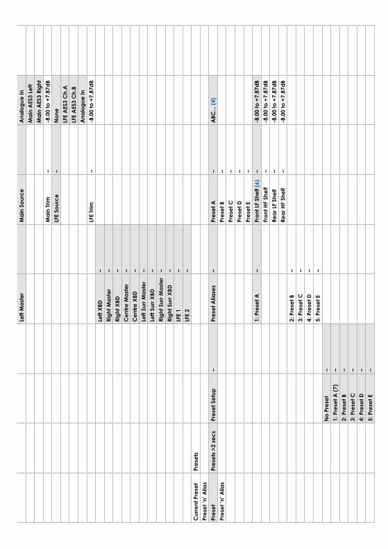
Summary Table
The table on the following two pages summarises the menu structure of these control functions and associated displays, with reference to the notes below:
1. Note that Aliases are assigned to speakers in the order that they are connected via the RJ45 In and Thru sockets. The speaker connected directly to the remote control is aloways alias number 1.
2. “Select” is the push button action of the rotary encoder.
3. The Mute button mutes all channels, in which condition the display backlight flashes.
4. For preset alias, select from alphabet/numerals using rotary encoder and click (up to 10 chars).
5. XBD channel aliases are only required if an IB2S XBD-A is integrated into a main monitor series surround monitoring system.
6. Front LCR ganged. Rear surrounds ganged.
7. Alias name of preset
8. Defaults to volume level and channel clip display after no remote activity for >60 sec.
9. If Trigger mode on, then the display shows “Awaiting Trigger” when the system is in standby. External trigger signal on is required on 1st loudspeaker in the chain.
10. Sets input level required to obtain rated output
Please Note that the final loudspeaker in the chain must have the loopback connector fitted to the RJ45 Remote Thru socket.!
43
44
45
46
47
48
49
50
51
52
53
54
55
56

Disp
lay
Butto
nsRo
tary
Sele
ct (2
)Ro
tary
Sele
ctRo
tary
Sele
ctRo
tary
Sele
ctVo
lum
e (8
)Vo
lum
e-4
8.5
to +
15dB
Cha
n A
ssig
nmen
tC
han
Clip
Volu
me/
Vloc
kBa
ck >
2 se
csM
enu
Pow
er O
ff–
Zzz
Aw
aitin
g Tr
igge
r(1
0)–
Trig
ger M
ode
Off
Men
u >2
sec
sSe
tup
–C
hann
el A
liase
s–
Ch.
1 (1
)–
Non
e–
Left
Mas
ter
–Le
ft XB
D (5
)–
Righ
t Mas
ter
–Ri
ght X
BD–
Cen
tre M
aste
r–
Cen
tre X
BD–
Left
Surr
Mas
ter
–Le
ft Su
rr XB
D–
Righ
t Sur
r Mas
ter
–Ri
ght S
urr X
BD–
LFE
1–
LFE
2–
All
Cha
nnel
Mut
eM
ute
(3)
Blac
klig
ht F
lash
esC
h.2
–C
h.3
–C
h.4
–C
h.5
–C
h.6
–C
h.7
–C
h.8
–C
h.9
–C
h.10
–C
h.11
–C
h.12
–A
nalo
gue
In S
ens
–+4
dB to
+20
dB–
(10)
12V
Trig
ger M
ode
– (9
)O
n–
–O
ff–
Left
Mas
ter
Mai
n So
urce
Ana
logu
e In
Mai
n A
ES3
Left
Mai
n A
ES3
Righ
tM
ain
Trim
–-8
.00
to +
7.87
dBLF
E So
urce
–N
one
LFE
AES
3 C
h.A
LFE
AES
3 C
h.B
Ana
logu
e In
LFE
Trim
–-8
.00
to +
7.87
dBLe
ft XB
D–
Righ
t Mas
ter
–Ri
ght X
BD–
Cen
tre M
aste
r–
Cen
tre X
BD–
Left
Surr
Mas
ter
–Le
ft Su
rr XB
D–
Righ
t Sur
r Mas
ter
–Ri
ght S
urr X
BD–
LFE
1–
LFE
2–
Cur
rent
Pre
set
Pres
ets
Pres
et ‘n
’ Alia
sPr
eset
Pres
ets
>2 s
ecs
Pres
et S
etup
–Pr
eset
Alia
ses
–Pr
eset
A–
ABC
... (4
)Pr
eset
‘n’ A
lias
Pres
et B
–Pr
eset
C–
Pres
et D
–Pr
eset
E–
1: P
rese
t A–
Fron
t LF
Shel
f (6)
–-8
.00
to +
7.87
dBFr
ont H
F Sh
elf
–-8
.00
to +
7.87
dBRe
ar L
F Sh
elf
–-8
.00
to +
7.87
dBRe
ar H
F Sh
elf
–-8
.00
to +
7.87
dB2:
Pre
set B
–3:
Pre
set C
–4:
Pre
set D
–5:
Pre
set E
–N
o Pr
eset
–1:
Pre
set A
(7)
–2:
Pre
set B
–3:
Pre
set C
–4:
Pre
set D
–5:
Pre
set E
–

The PMC range
The PMC range of professional monitors currently spans 27 different models, from the enormous
QB1 XBD-A flagship system down to the diminutive twotwo.5 active speaker. However, every
monitor is designed with the same care and attention, using shared families of drive units,
crossover designs and amplifiers. As a direct consequence they all enjoy the same family
characteristics of wide dispersion, low distortion, consistent voicing, and an even bass response
regardless of listening level. This feature allows different sizes of monitors to be used in concert to
create effective multichannel systems where space is at a premium.
QB1 XBD-A twotwo.543
44
45
46
47
48
49
50
51
52
53
54
55
56

We are confident that your main monitors will afford many years of trouble-free listening of the
highest order. However, in the unlikely event that they should require repair, all replacement parts
will exactly match the performance of those originally installed, because for every loudspeaker
we produce, we record the precise value of each component, along with the system response
as a whole.
For any issues that might arise, or for advice and service requirements, the primary point of contact
should be your authorised PMC dealer/distributor.If you do not have a local representative see
www.pmc-speakers.com and click on ‘where to buy’ to locate them.
Important Note:
Please do not return any products to PMC directly without first contacting our service department
by email at [email protected]. Alternatively you can fill out a service request form at
www.pmc-speakers.com/support/service-request
Service
43
44
45
46
47
48
49
50
51
52
53
54
55
56

All PMC loudspeakers are hand-built in the UK using components that are individually
matched to our reference model. This includes the structural integrity of every
cabinet, and the testing and recording of each individual component to guarantee
adherence to our strict tolerances. In this way we can ensure your purchase sounds
identical to the original design.
Each completed monitor undergoes a set of objective listening tests and
measurements. For example, frequency response sweeps ensure that the unit meets
our exacting performance criteria, and critical listening tests are conducted against
the reference model using a wide variety of audio material, from a benchmark BBC
speech recording to carefully selected classical music, pop and rock tracks.
Meticulous care and attention
43
44
45
46
47
48
49
50
51
52
53
54
55
56

If you do not have access to the internet fill in the warranty form on pages 49 and 50, and post pages 49-50 to us.
SIMPLY ACTIVATE YOUR 5-YEAR
WARRANTY ON-LINE
Warranty online
GO TO WWW.PMC-SPEAKERS.COM AND CLICK ON REGISTER PRODUCT
WARRANTY ON-LINE
43
44
45
46
47
48
49
50
51
52
53
54
55
56
43
44
45
46
47
48
49
50
51
52
53
54
55
56

WARRANTY CERTIFICATE - PART 1
Your copy to keep
Servicing and warranty issues – Please read the following carefully.
Non-UK clients
Contact your local dealer/distributor for the details of warranty repairs – see www.pmc-speakers.com and click on ‘where to buy’ for their details.
UK clients
In the unlikely event of a fault occurring with your PMC product please contact your dealer where the product was purchased.
Do not return a product to PMC without firstly contacting our technical department. If the product needs to be returned for service you will be issued with a Returns Authorisation number.
If a product is returned to PMC and subsequently is found to have no fault or a non-warranty fault there will be minimum charge of £50.00 plus the carriage for its return.
Proof of purchase is required for any claim covered by this warranty.
This product is warranted for a period of five years from the date of purchase or valid warranty registration which is either by receipt of the ‘Our Copy’ card or an on-line registration which must be made within ten days of purchase or receipt.
The warranty covers defects due to faulty materials or workmanship but does not cover defects arising from accidental damage, misuse or wear and tear. The warranty is void if any attempt has been made by persons not authorised by PMC to dismantle, repair or modify any part of the product.
Products must be returned using original packing material. This warranty does not cover damage in transit.
Note that the cost of the carriage to PMC is not covered by the warranty.
Returned products that are defective but no longer covered by warranty will be repaired or replaced at the discretion of PMC.
Please allow a minimum of 14 working days for return of warranty repairs.
This warranty does not affect your consumer rights under statutory law. This warranty certificate is only valid in the United Kingdom.
THE PROFESSIONAL MONITOR COMPANY LIMITED Holme Court Biggleswade SG18 9ST UK T +44 (0)1767 686300 F +44 (0)870 4441045
Please complete and retain this page for your own records
Product
Serial No’s
Date of purchase
Dealer’s name
Dealer’s address
Town
County
Postcode
Dealer’s Telephone No.
43
44
45
46
47
48
49
50
51
52
53
54
55
56

Product
Serial No’s
Date of purchase
Purchased from
Your name
Your email address
Your address
Town
County
Postcode/Zip code
WARRANTY CERTIFICATE - PART 2
Please complete and return this section – or simply complete the on-line registration at www.pmc-speakers.com and click on ‘register product.’
Help us to improve our products.
See over
PMC’s copy
43
44
45
46
47
48
49
50
51
52
53
54
55
56

Which magazines do you read?
HiFi Pro Lifestyle On-Line
HiFi Choice Future Music T3 mixonline.com
What HiFi Sound On Sound Stuff gearslutz.com
Stereophile Audio Media GQ avreview.co.uk
HiFi World Pro Sound News Mens Health avforums.com
HiFi Critic Resolution FHM HiFi WigWam.com
HiFi News Audio Fanzine Loaded What HiFi.com
HiFi+ IBE Maxim SoundonSound.com
Gramophone Tape Op Esquire SoundonSound/forum
Other Other Other Other
Please tell us how your new PMC loudspeakers perform. Your comments may appear on the customer quotes section for this product on our website – but don’t worry, the comments will be anonymous and your personal details will not be published.
‘We hope you enjoy your latest purchase as much as we enjoyed designing and building them – Thank you’
We value all of our clients’ comments. Please take a moment to help us improve.
If there is one thing we should change, what would it be?
Your comments — help us improve
43
44
45
46
47
48
49
50
51
52
53
54
55
56

Every component employed within a PMC product is measured, tested, matched
and recorded by hand. This analysis also applies to the final product to ensure
you receive an identical replica of the original reference model.
Inspection certificate
Enclosure finish
Assembly & Wiring
Driver installation
Enclosure seal
Level – Frequency
Pair matching
Active electronics inspection
Active electronics test
Listening test 1
Listening test 2
Final inspection
Accessory pack
User Guide
The above have all been carefully checked by the builder of your PMC monitors.
43
44
45
46
47
48
49
50
51
52
53
54
55
56
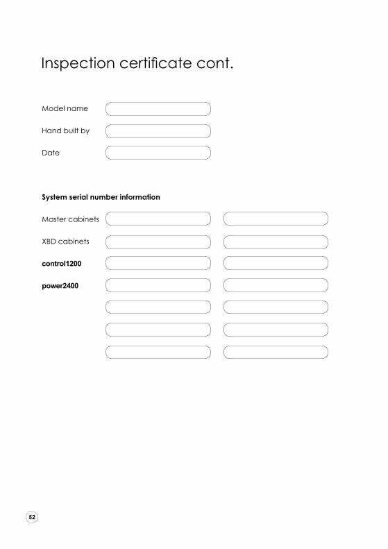
Inspection certificate cont.
43
44
45
46
47
48
49
50
51
52
53
54
55
56
Model name
Hand built by
Date
System serial number information
Master cabinets
XBD cabinets
control1200
power2400

Notes

© 2017 PMC. All rights reserved.
This document should not be construed as a commitment on the part of The Professional Monitor Company Limited (PMC). The information it contains is subject to change without notice. PMC assumes no responsibility for errors that may appear within this document. Information subject to change.
CE Conformity PMC passive loudspeakers conform to CE Directive LVD 73/23/EEC and EMC 89/336/EEC. WEEE European directive - PMC is a member of a National Compliance scheme and have gained the associated certification of compliance and the following registration number from the Environment Agency WEEE/GJ0101WU
WEEE EU DirectiveThis symbol on the product or in/on its packaging indicates that this product must not be disposed of with other household waste. It is the responsibility of the owner to dispose of waste equipment via a designated collection point for the recycling of waste electrical and electronic equipment. The recycling of your waste equipment is an attempt to conserve natural resources and ensures that it is recycled in a manner that protects human health and the environment. For more information about where you dispose of your waste equipment for recycling, please contact your local waste/recycling authority or the dealer from whom you purchased the product.

ULTIMATE MONITORING T + 44 (0) 1767 686300
W www.pmc-speakers.com
Job No. 898 - Nov 2017
PMC stock code 15584