maine department of transportation · maine department of transportation 1/4/2016 proposal id:...
TRANSCRIPT

Maine Department of Transportation
1/4/2016
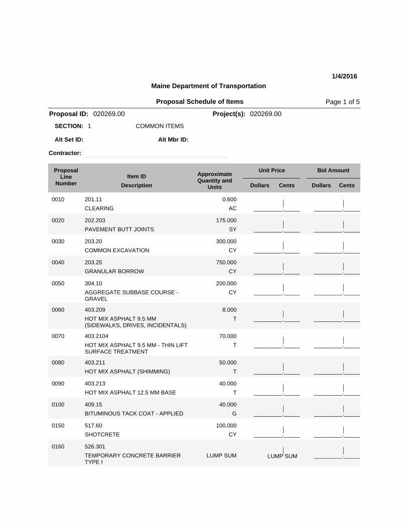
Proposal ID: 020269.00 Project(s): 020269.00
1 COMMON ITEMSSECTION:
Alt Set ID: Alt Mbr ID:
Contractor:
Bid AmountUnit PriceApproximateQuantity and
UnitsDescription
Item IDProposal
LineNumber Dollars Cents Dollars Cents
_________._____
0010 201.11
CLEARING AC
0.600
_________._____
_________._____
0020 202.203
PAVEMENT BUTT JOINTS SY
175.000
_________._____
_________._____
0030 203.20
COMMON EXCAVATION CY
300.000
_________._____
_________._____
0040 203.25
GRANULAR BORROW CY
750.000
_________._____
_________._____
0050 304.10
AGGREGATE SUBBASE COURSE -GRAVEL
CY
200.000
_________._____
_________._____
0060 403.209
HOT MIX ASPHALT 9.5 MM(SIDEWALKS, DRIVES, INCIDENTALS)
T
8.000
_________._____
_________._____
0070 403.2104
HOT MIX ASPHALT 9.5 MM - THIN LIFTSURFACE TREATMENT
T
70.000
_________._____
_________._____
0080 403.211
HOT MIX ASPHALT (SHIMMING) T
50.000
_________._____
_________._____
0090 403.213
HOT MIX ASPHALT 12.5 MM BASE T
40.000
_________._____
_________._____
0100 409.15
BITUMINOUS TACK COAT - APPLIED G
40.000
_________._____
_________._____
0150 517.60
SHOTCRETE CY
100.000
_________._____
0160 526.301
TEMPORARY CONCRETE BARRIERTYPE I
_________._____LUMP SUM LUMP SUM
Proposal Schedule of Items Page 1 of 5

Maine Department of Transportation
1/4/2016
Proposal ID: 020269.00 Project(s): 020269.00
1 COMMON ITEMSSECTION:
Alt Set ID: Alt Mbr ID:
Contractor:
Bid AmountUnit PriceApproximateQuantity and
UnitsDescription
Item IDProposal
LineNumber Dollars Cents Dollars Cents
_________._____
0170 606.23
GUARDRAIL TYPE 3C - SINGLE RAIL LF
312.500
_________._____
_________._____
0180 606.231
GUARDRAIL TYPE 3C - 15 FOOTRADIUS AND LESS
LF
25.000
_________._____
_________._____
0190 606.265
TERMINAL END - SINGLE RAIL -GALVANIZED STEEL
EA
1.000
_________._____
_________._____
0200 606.353
REFLECTORIZED FLEXIBLEGUARDRAIL MARKER
EA
4.000
_________._____
_________._____
0210 606.81
TANGENT GUARDRAIL TERMINAL -ENERGY ABSORBING
EA
1.000
_________._____
_________._____
0220 610.08
PLAIN RIPRAP CY
800.000
_________._____
_________._____
0230 613.319
EROSION CONTROL BLANKET SY
50.000
_________._____
_________._____
0240 615.07
LOAM CY
45.000
_________._____
_________._____
0250 618.14
SEEDING METHOD NUMBER 2 UN
10.000
_________._____
_________._____
0260 619.1201
MULCH - PLAN QUANTITY UN
10.000
_________._____
_________._____
0270 620.58
EROSION CONTROL GEOTEXTILE SY
1,600.000
_________._____
_________._____
0280 627.733
4" WHITE OR YELLOW PAINTEDPAVEMENT MARKING LINE
LF
1,380.000
_________._____
Proposal Schedule of Items Page 2 of 5

Maine Department of Transportation
1/4/2016
Proposal ID: 020269.00 Project(s): 020269.00
1 COMMON ITEMSSECTION:
Alt Set ID: Alt Mbr ID:
Contractor:
Bid AmountUnit PriceApproximateQuantity and
UnitsDescription
Item IDProposal
LineNumber Dollars Cents Dollars Cents
_________._____
0290 627.78
TEMPORARY 4 INCH PAINTEDPAVEMENT MARKING LINE, WHITEOR YELLOW
LF
1,380.000
_________._____
_________._____
0300 629.05
HAND LABOR, STRAIGHT TIME HR
15.000
_________._____
_________._____
0310 631.12
ALL PURPOSE EXCAVATOR(INCLUDING OPERATOR)
HR
20.000
_________._____
_________._____
0320 631.172
TRUCK - LARGE (INCLUDINGOPERATOR)
HR
20.000
_________._____
_________._____
0330 631.18
CHAIN SAW RENTAL (INCLUDINGOPERATOR)
HR
10.000
_________._____
_________._____
0340 631.22
FRONT END LOADER (INCLUDINGOPERATOR)
HR
20.000
_________._____
_________._____
0350 639.19
FIELD OFFICE TYPE B EA
1.000
_________._____
0360 643.72
TEMPORARY TRAFFIC SIGNAL _________._____LUMP SUM LUMP SUM
_________._____
0370 652.33
DRUM EA
25.000
_________._____
_________._____
0380 652.34
CONE EA
50.000
_________._____
_________._____
0390 652.35
CONSTRUCTION SIGNS SF
220.000
_________._____
Proposal Schedule of Items Page 3 of 5

Maine Department of Transportation
1/4/2016
Proposal ID: 020269.00 Project(s): 020269.00
1 COMMON ITEMSSECTION:
Alt Set ID: Alt Mbr ID:
Contractor:
Bid AmountUnit PriceApproximateQuantity and
UnitsDescription
Item IDProposal
LineNumber Dollars Cents Dollars Cents
_________._____
0400 652.36
MAINTENANCE OF TRAFFICCONTROL DEVICES
CD
53.000
_________._____
_________._____
0410 652.38
FLAGGER HR
330.000
_________._____
0420 656.75
TEMPORARY SOIL EROSION ANDWATER POLLUTION CONTROL
_________._____LUMP SUM LUMP SUM
0430 659.10
MOBILIZATION _________._____LUMP SUM LUMP SUM
Section: 1 _________._____Total:
2 POLYETHYLENE ALTERNATESECTION:
1ALAlt Set ID: Alt Mbr ID:
Contractor:
Bid AmountUnit PriceApproximateQuantity and
UnitsDescription
Item IDProposal
LineNumber Dollars Cents Dollars Cents
_________._____
0120 509.201
CULVERT SLIPLINING LF
130.000
_________._____
0130 509.203
HIGH DENSITY POLYETHYLENE FISHWEIRS
_________._____LUMP SUM LUMP SUM
Section: 2 _________._____Total:
Proposal Schedule of Items Page 4 of 5
Maine Department of Transportation
1/4/2016
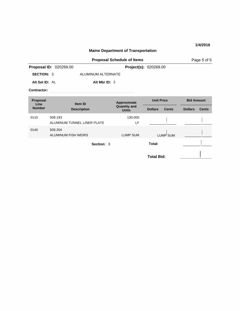
Proposal ID: 020269.00 Project(s): 020269.00
3 ALUMINUM ALTERNATESECTION:
2ALAlt Set ID: Alt Mbr ID:
Contractor:
Bid AmountUnit PriceApproximateQuantity and
UnitsDescription
Item IDProposal
LineNumber Dollars Cents Dollars Cents
_________._____
0110 509.193
ALUMINUM TUNNEL LINER PLATE LF
130.000
_________._____
0140 509.204
ALUMINUM FISH WEIRS _________._____LUMP SUM LUMP SUM
Section: 3 _________._____Total:
Total Bid: _________._____
Proposal Schedule of Items Page 5 of 5


Freeport Route 1
WIN 020269.00 1/4/2015
Page 1 of 1
SPECIAL PROVISION SECTION 502
Fish Passage Weirs Measurement & Payment Weirs satisfactorily installed and accepted will be measured as one lump sum price, in accordance with the plans or authorized changes to the Plans. The accepted work will be paid for at the Contract lump sum price. Payment will be full compensation for installing aluminum sheeting and all incidentals necessary to complete the work satisfactorily. Weir Plate Detail for aluminum fish weirs will be supplied to the Contractor before the Pre-Construction Meeting. Add the following Pay Item and its associated Pay Unit: Payment will be made under: Pay Item Pay Unit 509.204 Aluminum Fish Weirs Lump

Freeport Route 1
WIN 020269.00 12/29/2015
Page 1 of 3
SPECIAL PROVISION SECTION 502
ANNULAR SPACE GROUTING Description: This work shall consist of providing and placing non-shrink grout as described below. The annular space (void between the host and liner pipes) shall be completely grouted to support the liner and provide long-term stability. The Contractor shall provide testing of the materials and methods for compliance with the following requirements. Prior to any work the Contractor shall furnish an acceptable plan for performing and testing the grouting. Preparation: After slip liner installation but prior to grouting, bulk heading of the ends and venting shall be constructed. After bulk heading of the ends and venting, test the integrity of the installed liner pipe and constructed bulkheads for any leaks. Planned Vents: The Contractor shall submit shop drawings or indicate in the installation plan the proposed number and location of vents relative to pipe diameter and stiffness for the grouting operations. Materials: The grout material shall consist of portland cement (portland cement and fly ash) and/or additives as described in the following Subsections of Division 700 - Materials: Portland Cement 701.01 Water 701.02 Air-Entraining Admixtures 701.03 Fine Aggregate 701.01 Fly Ash 701.10 Type F or C Chemical Admixtures 701.04 Accelerating Admixtures AASHTO M-194 Type “C”
(a) Compressive Strength: The grout shall have a minimum penetration resistance of 700 kPa [100 psi] in 24 hours when tested in accordance with ASTM C403 and a minimum compressive strength of 3500 kPa [500 psi] in 28 days when tested in accordance with ASTM C495 or C109.
(b) Performance Requirements: The Contractor shall submit the proposed grout mix, methods, plans and criteria of the grouting operations. The grouting system shall have sufficient gauges, monitoring devices and tests to determine the effectiveness of the grouting operation and to ensure compliance with the liner pipe specifications and design parameters.
Freeport Route 1
WIN 020269.00 12/29/2015
Page 2 of 3
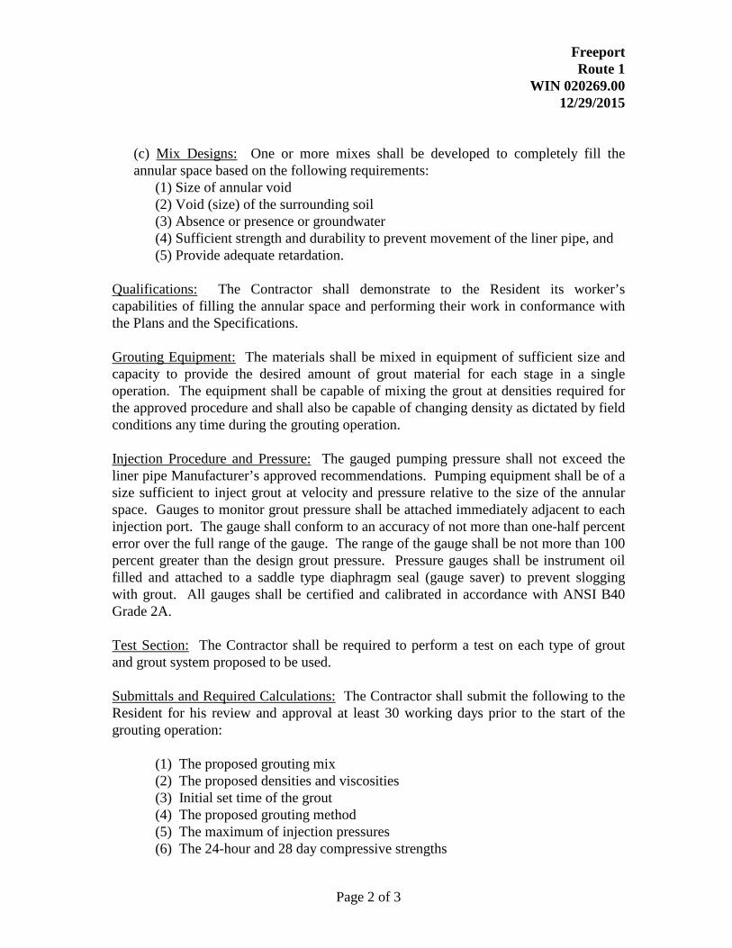
(c) Mix Designs: One or more mixes shall be developed to completely fill the annular space based on the following requirements:
(1) Size of annular void (2) Void (size) of the surrounding soil (3) Absence or presence or groundwater (4) Sufficient strength and durability to prevent movement of the liner pipe, and (5) Provide adequate retardation.
Qualifications: The Contractor shall demonstrate to the Resident its worker’s capabilities of filling the annular space and performing their work in conformance with the Plans and the Specifications. Grouting Equipment: The materials shall be mixed in equipment of sufficient size and capacity to provide the desired amount of grout material for each stage in a single operation. The equipment shall be capable of mixing the grout at densities required for the approved procedure and shall also be capable of changing density as dictated by field conditions any time during the grouting operation. Injection Procedure and Pressure: The gauged pumping pressure shall not exceed the liner pipe Manufacturer’s approved recommendations. Pumping equipment shall be of a size sufficient to inject grout at velocity and pressure relative to the size of the annular space. Gauges to monitor grout pressure shall be attached immediately adjacent to each injection port. The gauge shall conform to an accuracy of not more than one-half percent error over the full range of the gauge. The range of the gauge shall be not more than 100 percent greater than the design grout pressure. Pressure gauges shall be instrument oil filled and attached to a saddle type diaphragm seal (gauge saver) to prevent slogging with grout. All gauges shall be certified and calibrated in accordance with ANSI B40 Grade 2A. Test Section: The Contractor shall be required to perform a test on each type of grout and grout system proposed to be used. Submittals and Required Calculations: The Contractor shall submit the following to the Resident for his review and approval at least 30 working days prior to the start of the grouting operation:
(1) The proposed grouting mix (2) The proposed densities and viscosities (3) Initial set time of the grout (4) The proposed grouting method (5) The maximum of injection pressures (6) The 24-hour and 28 day compressive strengths

Freeport Route 1
WIN 020269.00 12/29/2015
Page 3 of 3
(7) Proposed grout stage volumes (8) Bulkhead designs (9) Buoyant force calculations (10) Flow control (11) Provisions for service connections (12) Pressure gauge certification (13) Vent location plans (14) Certification that grouting plan conforms with all provisions, cautions and restrictions or the liner manufacturer.
These shall be submitted as a complete package for a single or sample section only. The Contractor shall notify the Resident of any changes to be made in grouting. Method of Measurement: Grout satisfactorily placed and accepted will be measured by cubic yard placed. Grout satisfactorily placed and accepted will be measured by the cubic yard, in accordance with the pay limits established, if such limits have been established. Basis of Payment: The accepted work done under Annular Space Grouting including all forms, berms, bulkheads, pumping, and incidentals necessary will be considered incidental to Item 509.201 Culvert Slip-lining.

Freeport Route 1
WIN 020269.00 1/4/2016
Page 1 of 3
SPECIAL PROVISION SECTION 509
ALUMINUM TUNNEL LINER PLATE 509.01 Description: This work shall consist of designing, furnishing, and inserting an aluminum alloy tunnel liner plate into an existing culvert and constructing seals at the ends of the new pipe and filling the voids between the new and existing culvert with grout in accordance with the plans and specifications and in reasonably close conformity with the lines and grades shown in the Contract Documents. 509.02 Material: Liner Plates:
Liner Plates shall be fabricated from aluminum plates conforming to alloy 5052 as defined by ASTM B 209. Plates shall be punched and curved to suit the tunnel liner plate cross section and the tunnel geometry section as shown. Standard corrugated aluminum structural plate with 9” x 2-1/2” corrugations will not be considered for this project. End plates shall be neatly cut to the skew and slope shown on the Plans. Burnt or cut edges shall be free of oxide and burrs.
All plates shall be punched for bolting on both longitudinal and circumferential seams and shall be so fabricated as to permit complete erection from the inside of the tunnel. The longitudinal seam shall be of the lapped type, with an offset equal to the gage of metal for the full width of plate to allow the cross section of the plate to be continuous through the seam. Circumferential bolt hole spacing shall be 6 ¼”. Grout holes shall be two inches (2”) in diameter and shall be provided as shown on the plans to permit grouting as the assembly of the liner plate proceeds.
Marking:
Individual plates shall be marked with identification numbers and letters that allow for clear field identification with respect to the approved shop drawings.
Bolts and Nuts:
All nuts and bolts used on the structure are to be galvanized steel. Bolts and nuts shall be 5/8” in diameter and length as recommended by the manufacturer. Bolts shall conform to ASTM A 449, TYPE 1 OR ASTM A 307. For plate thickness less than 0.200”, the bolts shall be A 307, GRADE A. All circumferential bolts may be A 307, GRADE A. Nuts shall conform to ASTM A 563, GRADE A, HEX. Galvanizing when required shall be in accordance with the requirements of ASTM B-695, CLASS 50.

Freeport Route 1
WIN 020269.00 1/4/2016
Page 2 of 3
509.03 Fabrication and Submittals: The Contractor shall submit design calculations (assuming no structural contribution from the host structure) that include thickness calculations per AASHTO LRFD and shop drawings for the tunnel liner plate to the Department for approval. The liner plate material shall be one thickness larger than required by the AASHTO calculations for added durability. So if 0.150” plate is required structurally, the manufacturer will provide 0.175” plate. A Maine Licensed Professional Engineer shall sign and seal all structural design calculations and drawings. The Contractor shall prepare and submit Shop Drawings, erection/assembly diagrams, or other necessary Working Drawings in accordance with Section 100 of the Standard Specifications. These drawings will be reviewed and approved in accordance with the applicable requirements of Section 100. Drawings shall conform to Section 105.7 - Working Drawings. 509.04 General Construction Requirements: Handle and assemble all elements of the structure in accordance with the manufacturer’s instructions and the Standard Specification, except as modified herein, on the plans or as ordered by the Resident in writing. The Contractor will dewater, inspect, and clean the existing culvert. The Contractor shall provide strutting and bracing to ensure the stability of the existing culvert during this operation. The pipe sections shall be braced against the existing culvert so that the new pipe shall remain in place during grouting operations. The Contractor is responsible for assuring that the pipe does not lift, float or shift during the grouting operation. A minimum 25 mm [1 in] of grout shall be between the new and existing culverts. Bracing material shall not significantly impede grout flow into the annular space between the culverts.
Grout retaining bulkheads: Place plywood or material of equivalent strength, in the annular space at each end of the culvert, to retain grout. Seals may be left in place providing they do not interfere with bank protection and/or fish passage.
Installation:
Liner plate shall be assembled in accordance with manufacturer’s recommendations. Longitudinal seams shall be staggered between rings. Voids occurring between liner plate and existing structure or ground shall be grouted until completely filled. Grout material and method of grouting shall be reviewed by the manufacturer and approved by the engineer prior to the commencement of work.

Freeport Route 1
WIN 020269.00 1/4/2016
Page 3 of 3
509.09 Basis of Payment: The accepted structure will be paid for at the respective Contract unit price per linear foot, complete in place, which price shall be full compensation for: design and engineering of proposed structures; furnishing all labor, materials, equipment necessary to manufacture, assemble and install the pipe complete and in place, and all incidental items required to complete the work, including: but not limited to dewatering, preparation of the bed, the horizontal end reinforcing ribs, cleaning, inspecting, strutting, bracing, skids, concrete grout filler, joint bands, seals, installing grout nipples, plugs, fittings, hardware, damaged pipe repair, bolts and the calibrated torque wrench for use by the Resident. Grout used to fill the annular space and backfill voids will be completed according to Special Provision Section 502, Annular Space Grouting.
Payment will be made under: Pay Item Pay Unit 509.193 Aluminum Tunnel Liner Plate Linear Foot

Freeport Route 1
WIN 020269.00 12/31/2015
Page 1 of 4
SPECIAL PROVISION SECTION 509
CULVERT SLIPLINING (Plastic Pipe)
Description: This work shall consist of inserting a new pipe into an existing culvert and constructing seals at the ends of the new pipe and filling the voids between the new and existing culvert pipe with grout in accordance with the plans and specifications. General Construction Requirements: Handle and assemble all elements of the structure in accordance with the manufacturer’s instructions, except as modified herein, on the plans or as ordered by the Resident in writing. The Contractor shall submit fabrication details including assembly drawings, pipe insertion methods, internal joint coupling and bracing details, to the Resident for approval. The Resident will be allowed a minimum of 10 working days to review the Contractor’s submittal. The Contractor will dewater, inspect, and clean the existing culvert. The Contractor shall provide strutting and bracing to ensure the stability of the existing culvert during this operation.
The Contractor may push or pull or use a combination of both to get the new pipe sections into place. When pushing is used, the jacking force must be uniformly distributed around the perimeter of the liner pipe to avoid the possibility of damaging the pipe due to a concentrated jacking load. The Contractor shall utilize skids in the existing culvert, to facilitate placement of the pipe sections. The displacement between adjacent pipe ends shall not exceed 13 mm [1/2 in].
The pipe sections shall be braced against the existing culvert so that the new pipe shall remain in place during grouting operations. The Contractor is responsible for assuring that the pipe does not “Float” during the grouting operation. A minimum 25 mm [1 in] of grout shall be between the new and existing culverts. Bracing material shall not significantly impede grout flow into the annular space between the culverts. Seals: Place plywood or material of equivalent strength, in the annular space at each end of the culvert, to retain grout. Seals may be left in place providing they do not interfere with bank protection and/or fish passage.
Material: Pipe and Fittings - Reference Specifications:

Freeport Route 1
WIN 020269.00 12/31/2015
Page 2 of 4
ASTM F-894: Standard Specification for Polyethylene (PE) Large Diameter Profile Wall Sewer and Drain Pipe.
CSA B 137.1: Polythylene Pipe, Tubing and Fittings for Cold Water Pressure Services. ASTM D-3350: Standard Specification for Polyethylene Plastics Pipe and Fittings
Materials. ISO 9002: Model for Quality Assurance in Production and Installation.
1) The pipe shall be manufactured from polyethylene resin compound with a minimum cell classification of PE 345464C in accordance with ASTM D3350. This material shall have a long term hydrostatic strength of 1600 psi when tested and analyzed by ASTM D2837, and shall be a Plastic Pipe Institute (PPI) listed compound.
2) The raw material shall contain a minimum of 2%, well dispersed, carbon black.
Additives, which can be conclusively proven not to be detrimental to the pipe may also be used, provided the pipe produces meets the requirements of this standard.
3) The pipe shall contain no recycled compound except that generated in the
manufacturer’s own plant form resin of the same specification and from the same raw material supplier.
4) Compliance with the requirements of this paragraph shall be certified in writing by
the pipe supplier. 5) Manufacturer’s Quality System shall be certified by an appropriate independent body
to meet the requirements of the ISO 9002 Quality Management Program. Pipe Design The pipe shall be designed as a stand alone direct burial pipe. The pipe shall be able to support the earth and live load by itself with no additional capacity from the existing pipe or the annular space grout.
1. The pipe shall be designed in accordance with the relationships of the ISO-
modified formula (see ASTM F894).
2. The design pressure rating P shall be derived using the ISO modified formula and shall be its normal working pressuring in pounds per square inch at temperatures up to 730F.
3. The Hydrostatic Design Stress shall be 800 psi for PE 3408 materials.

Freeport Route 1
WIN 020269.00 12/31/2015
Page 3 of 4
4. The pipe dimensions shall be as specified in manufacturer’s literature.
Marking: The following shall be continuously indent printed on the pipe or spaced at intervals not exceeding 1.5 m (5 feet).
1. Name and/or trademark of the pipe manufacturer. 2. Nominal pipe size 3. Dimension Ratio 4. The letters PE followed by the polyethylene grade per ASTM D3350, followed by
the Hydrostatic Design basis in 100’s of psi e.g. PE 3408. 5. Manufacturing Standard Reference e.g. ASTM F 894 6. A production code from which the date and place of manufacture can be
determined. Joining Methods: The polyethylene pipe shall be joined by extrusion welding or other means in accordance with the manufacturer’s recommendations and approved by the Resident. The pipe manufacturer shall provide an outline of recommended field quality control procedures to be performed on the polyethylene system components. Construction Requirements: The sections of pipe shall be assembled and joined together prior to insertion into the existing culvert. Assembly shall be accomplished above ground, either at the job-site or at a remote location. The pipe shall be welded in accordance with the manufacturer’s recommendations and approved by the Resident.
The polyethylene liner pipe may be inserted into the existing pipe with a power winch and steel cable connected to the end of the pipe in an appropriate manner. The pipe manufacturer’s recommendations should be followed regarding the most appropriate method of attaching the cable to the liner pipe. If required, a special pulling head may be attached to the end of the liner pipe to facilitate easy connection of the pulling cable.
Basis of Payment:

Freeport Route 1
WIN 020269.00 12/31/2015
Page 4 of 4
Payment for culvert slip-lining will be paid for at the Contract unit price per linear foot, complete in place. Culvert slip-lining includes full compensation for furnishing all labor, materials, equipment necessary to manufacture, assemble and install the pipe complete and in place, including: but not limited to dewatering, cleaning, inspecting, strutting, bracing, skids, concrete grout filler, joint bands, seals, installing grout nipples, plugs, fittings, hardware, and damaged pipe repair. Grout used to fill the annular space and backfill voids will be completed according to Special Provision Section 502, Annular Space Grouting. Payment will be made under: Pay Item Pay Unit
509.201 Culvert Slip Lining Linear Foot

Freeport Route 1
WIN 020269.00 December 29, 2015
Page 1 of 7
SPECIAL PROVISION SECTION 517 SHOTCRETE
Description This work shall include preparation of existing surfaces and the application of a shotcrete mix by pneumatic pressure as a means of filling the voids between riprap stones as indicated on the plans, filling the interior wall voids between the granite stones in the existing culvert, and in accordance with this Special Provision. Shotcrete shall conform to all requirements of ACI 506.2 “Specifications for Materials, Proportioning, and Application of Shotcrete”, published by the American Concrete Institute, Detroit, Michigan, except as modified by the requirements of this project specification. Shotcrete shall consist of an application of one or more layers of mortar or concrete conveyed through a hose and pneumatically projected at a high velocity against a prepared surface. Shotcrete shall be produced by either a dry-mix or a wet-mix process. The wet-mix process consists of thoroughly mixing all the ingredients except accelerating admixtures but including the mixing water, introducing the mixture into the delivery equipment and delivering it, by positive displacement, to the nozzle. The wet-mix shotcrete shall then be air jetted from the nozzle at high velocity onto the surface. Dry-mix process is shotcrete without mixing water which is conveyed through the hose pneumatically and the mixing water is introduced at the nozzle. For additional descriptive information, the Contractor’s attention is directed to the American Concrete Institute Standard “Guide to Shotcrete (ACI 506R-90)”. Qualifications The work shall be performed by fully qualified personnel experienced in this type of work. 1. The foreman shall have at least five years of shotcrete experience and at least two years as
a nozzleman. 2. The nozzleman shall have at least two years recent experience of satisfactory work as a
nozzleman. 3. Evidence of the foreman and nozzleman’s experience of satisfactory work in similar
capacities elsewhere shall be provided. Materials All materials for shotcrete shall conform to the following requirements.
Cement AASHTO M-85, ASTM C150, Type I, II, III or IV. Fine Aggregate AASHTO M-6, ASTM C33 clean, natural. Coarse Aggregate AASHTO M-80, Class B for quality. Water Potable, clean, and free from substances deleterious to
concrete and steel or elements that would stain. Chemical Admixtures ASTM C1141 and the following: Water-reducer AASHTO M-194, Type A, D, F, G or Superplasticizer ASTM C494 Type A, D, F, G

Freeport Route 1
WIN 020269.00 December 29, 2015
Page 2 of 7
Air-Entraining Agent AASHTO M-194/ASTM C260 Plasticizers AASHTO M-194 Type A, D, F, G or ASTM C494 Mineral Admixtures
Fly Ash AASHTO M-295, ASTM C618 Type F or C Silica Fume ASTM C1240, 90% minimum silicon dioxide solids
content, not to exceed 12% by weight of cement. In addition, silica fume shall conform to the requirements of Section 502.
Polypropylene Fibers ACI Standard, Polypropylene Fibers, 1 inches in length, 1½ lb/yd3
Steel Fibers ASTM A820 Type I, II, or III, Deformed, Steel Fibers, 1 in to 1 ⅜ inches in length, minimum aspect ratio of 60.
Curing Compounds AASHTO M-148 Type 1 D of Type 2 Pre-packaged Shotcrete ASTM C928
The use of other admixtures shall not be used unless approved by the Resident. Admixtures used to entrain air, to reduce water-cement ratio, to retard or accelerate setting time, or to accelerate the development of strength, shall be thoroughly mixed into the shotcrete at the rate specified by the manufacturer unless specified otherwise. Accelerating additives shall be compatible with the cement used, be non-corrosive to steel and shall not promote other detrimental effects such as cracking or excessive shrinkage. The maximum allowable chloride ion content of all ingredients shall not exceed 0.10% when tested to AASHTO T260. Premixed and pre-packaged concrete products specifically manufactured as a shotcrete product may be provided for on-site mixed shotcrete if approved by the Resident. The packages shall contain materials conforming to the materials portion of this specification. Materials Storage and Handling Materials shall be delivered, stored, and handled to prevent contamination, segregation, corrosion, or damage. Liquid admixtures shall be stored to prevent evaporation and freezing. Cement shall be adequately stored to prevent moisture degradation and partial hydration. Cement that has become caked or lumpy shall not be used. Aggregates shall be stored so that segregation and the inclusion of foreign materials are prevented. The bottom 6 in of aggregate piles in contact with the ground shall not be used. Submittals The following submittals shall be provided by the Contractor for the Resident’s review and approval. The Contractor will not be allowed to begin culvert repairs until all submittal requirements are satisfied and found acceptable to the Resident. Changes or deviations from the approved submittals must be resubmitted for approval. Adjustments in contract time will not be allowed for incomplete submittals.
Freeport Route 1
WIN 020269.00 December 29, 2015
Page 3 of 7
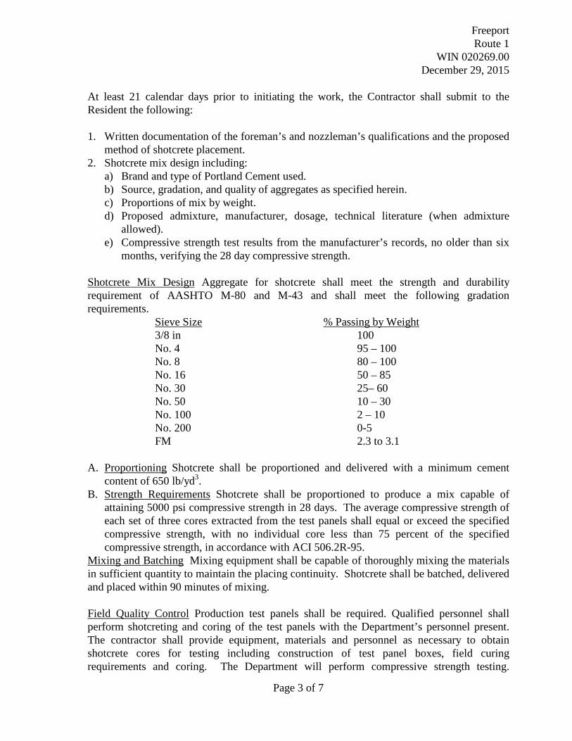
At least 21 calendar days prior to initiating the work, the Contractor shall submit to the Resident the following: 1. Written documentation of the foreman’s and nozzleman’s qualifications and the proposed
method of shotcrete placement. 2. Shotcrete mix design including:
a) Brand and type of Portland Cement used. b) Source, gradation, and quality of aggregates as specified herein. c) Proportions of mix by weight. d) Proposed admixture, manufacturer, dosage, technical literature (when admixture
allowed). e) Compressive strength test results from the manufacturer’s records, no older than six
months, verifying the 28 day compressive strength. Shotcrete Mix Design Aggregate for shotcrete shall meet the strength and durability requirement of AASHTO M-80 and M-43 and shall meet the following gradation requirements. Sieve Size % Passing by Weight 3/8 in 100 No. 4 95 – 100 No. 8 80 – 100
No. 16 50 – 85 No. 30 25– 60 No. 50 10 – 30 No. 100 2 – 10 No. 200 0-5 FM 2.3 to 3.1
A. Proportioning Shotcrete shall be proportioned and delivered with a minimum cement content of 650 lb/yd3.
B. Strength Requirements Shotcrete shall be proportioned to produce a mix capable of attaining 5000 psi compressive strength in 28 days. The average compressive strength of each set of three cores extracted from the test panels shall equal or exceed the specified compressive strength, with no individual core less than 75 percent of the specified compressive strength, in accordance with ACI 506.2R-95.
Mixing and Batching Mixing equipment shall be capable of thoroughly mixing the materials in sufficient quantity to maintain the placing continuity. Shotcrete shall be batched, delivered and placed within 90 minutes of mixing. Field Quality Control Production test panels shall be required. Qualified personnel shall perform shotcreting and coring of the test panels with the Department’s personnel present. The contractor shall provide equipment, materials and personnel as necessary to obtain shotcrete cores for testing including construction of test panel boxes, field curing requirements and coring. The Department will perform compressive strength testing.

Freeport Route 1
WIN 020269.00 December 29, 2015
Page 4 of 7
Shotcrete final acceptance will be based on obtaining the specified 28 day compressive strength. Shotcreting may commence upon initial approval of the design mix and nozzlemen. Production Test Panels At least one production test panel shall be furnished during each day of production of shotcrete. The production test panels shall be constructed simultaneously with the shotcrete facing installation at times designated by the Resident. Production test panels shall be made with the minimum dimensions of 18 x 18 inch and at least 6 inch thick. Test Panel Curing, Test Specimen Extraction and Testing Immediately after shooting, the test panels shall be field moist cured by covering and tightly wrapping with a sheet of material meeting the requirements of ASTM C 171 until delivered to the testing lab or test specimens are extracted. The test panels shall not be immersed in water. The test panels for the first 24 hours after shooting shall not be disturbed. At least three 3 inch diameter core samples shall be cut from each unreinforced production test panel for compressive strength testing. The Contractor shall extract the test specimens from test panels in the field within 48 hours of shooting the panel. The panels shall be kept in their forms when transported. Cores shall not be taken from the outer 6 inch of test panels measured in from the outside edges of the panel’s form. The cores and container shall be clearly marked to identify the core locations. For production testing, the production section of the unformed superstructure repair represented by the production test panel cores shall be marked on the cores and the container. Immediately wrap cores in wet burlap or material in accordance with the requirements of ASTM C 171 and seal in a plastic bag. The Department shall take possession of the cores immediately after extraction. The remainder of the panels shall become the property of the contractor. The Department will perform the compressive strength testing. Upon delivery to the testing lab, samples will be placed in the moist room until the time of test. When the test length of a core is less than twice the diameter, the correction factors given in AASHTO T 24/ASTM C 42 will be applied to obtain the compressive strength of individual cores. Three cores will be tested at 28 days for compressive strength per AASHTO T 24/ASTM C 42. Construction Requirements The construction sequence shall be in accordance with the approved submittal, unless otherwise approved by the Resident.

Freeport Route 1
WIN 020269.00 December 29, 2015
Page 5 of 7
A. Equipment 1. The shotcreting equipment selected must be capable of metering the mix through a
hose to the nozzle for projecting at high velocity onto the surface to be shotcreted. 2. The gun shall be either the double chamber or the rotary type capable of continuous
delivery of material. Gaskets in the equipment must be kept in good condition to avoid reduced pressure and consequent reduced velocity of material through the hose.
3. The air compressor may be any standard type capable of sufficient pressures and volume of air to convey the material through the longest hose delivery. The air compressor capacity must have allowance for air used in removing rebound and other incidental work. The air hose shall be equipped with filters to prevent any oil or grease from contaminating the shotcrete.
4. Water pressure shall be maintained at a minimum 15 psi higher than the highest air pressure required for placing the material. Both air and water pressure shall be uniformly steady.
B. Surface Preparation: The Contractor shall trim vegetation and remove loose foreign
materials from within the stone voids of which shotcrete will be applied. Care shall be taken not to disturb existing stones in place. When necessary, earth surfaces to which shotcrete is to be applied shall be firmly compacted. All surfaces shall be moistened before application of shotcrete. Shotcrete shall not be applied to mud, uncompacted earth, surfaces in standing water or frozen surfaces. All such prepared surfaces shall be inspected and accepted by the Resident prior to the application of shotcrete.
C. Placement: The Contractor shall have all equipment and materials required for curing
available at the site and ready for use before placement of shotcrete begins. No shotcrete shall be placed except in the presence of the MaineDOT Resident. The Contractor shall give reasonable notice to the Resident each time a shotcrete placement is scheduled. Such notice shall be far enough in advance to give the Resident adequate time to inspect the surfaces of which the shotcrete is to be applied.
Shotcrete shall be delivered to the holes between stones by any means that will insure uniformity and prevent segregation.
The nozzle shall be held at an angle approximately perpendicular to the working face and at a distance so that rebound will be minimal and compaction will be maximized. Thickness, methods of support, air pressure, and rate of placement of shotcrete shall be controlled to prevent sagging or sloughing of freshly applied shotcrete. The approximate depth of the finished grade of shotcrete between the stones shall be established prior to placement and must be accepted by the Resident. Approximately 75% of the voids or spaces between stones shall be filled with shotcrete.
Freeport Route 1
WIN 020269.00 December 29, 2015
Page 6 of 7
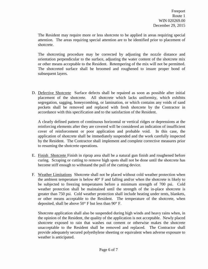
The Resident may require more or less shotcrete to be applied in areas requiring special attention. The areas requiring special attention are to be identified prior to placement of shotcrete. The shotcreting procedure may be corrected by adjusting the nozzle distance and orientation perpendicular to the surface, adjusting the water content of the shotcrete mix or other means acceptable to the Resident. Retempering of the mix will not be permitted. The shotcreted surface shall be broomed and roughened to insure proper bond of subsequent layers.
D. Defective Shotcrete Surface defects shall be repaired as soon as possible after initial
placement of the shotcrete. All shotcrete which lacks uniformity, which exhibits segregation, sagging, honeycombing, or lamination, or which contains any voids of sand pockets shall be removed and replaced with fresh shotcrete by the Contractor in accordance with this specification and to the satisfaction of the Resident.
A clearly defined pattern of continuous horizontal or vertical ridges or depressions at the reinforcing elements after they are covered will be considered an indication of insufficient cover of reinforcement or poor application and probable void. In this case, the application of shotcrete shall be immediately suspended and the work carefully inspected by the Resident. The Contractor shall implement and complete corrective measures prior to resuming the shotcrete operations.
E. Finish Shotcrete Finish in riprap area shall be a natural gun finish and roughened before
curing. Scraping or cutting to remove high spots shall not be done until the shotcrete has become stiff enough to withstand the pull of the cutting device.
F. Weather Limitations Shotcrete shall not be placed without cold weather protection when the ambient temperature is below 40° F and falling and/or when the shotcrete is likely to be subjected to freezing temperatures before a minimum strength of 700 psi. Cold weather protection shall be maintained until the strength of the in-place shotcrete is greater than 750 psi. Cold weather protection shall include heating under tents, blankets, or other means acceptable to the Resident. The temperature of the shotcrete, when deposited, shall be above 50° F but less than 90° F.
Shotcrete application shall also be suspended during high winds and heavy rains when, in the opinion of the Resident, the quality of the application is not acceptable. Newly placed shotcrete exposed to rain that washes out cement or otherwise makes the shotcrete unacceptable to the Resident shall be removed and replaced. The Contractor shall provide adequately secured polyethylene sheeting or equivalent when adverse exposure to weather is anticipated.

Freeport Route 1
WIN 020269.00 December 29, 2015
Page 7 of 7
G. Curing An approved curing cover (or compound) shall be applied within 18 hours after finishing. After surface water has evaporated from the finished surface, shotcrete exposed to sunlight shall be immediately treated for curing. Finished shotcrete shall be cured for a minimum of 48 hours before flushed with water, unless otherwise directed by the Resident, and flush water must be collected as per Section 656.
Safety Requirements Appropriate eye and dust protection equipment shall be used during shotcrete application. Cement and other admixtures are caustic and may cause eye, skin, and respiratory irritation unless safety measures are taken. Adequate ventilation shall be required. Nozzlemen and helpers shall as a minimum be equipped with gloves, respirators, eye protection and adequate protective clothing during the application of shotcrete. The Contractor is responsible for meeting all Federal, State, and Local Safety Code Requirements. Method of Measurement The shotcrete used for the filling of voids between stones applied and accepted in accordance with the plans, will be measured by the cubic yard as determined from the theoretical yield of the design mix or in the case of transit mixed shotcrete, by delivery ticket as directed by the Resident. Basis of Payment The accepted quantity of shotcrete used for the filling of voids between stones will be paid for at the Contract unit price per cubic yard for shotcrete. Payment for the unit price will be full compensation for preparing surfaces, applying shotcrete, constructing test panels, extracting cores, and furnishing all materials, equipment, labor, and incidentals necessary to complete the work. Payment will be made under: Pay Item Pay Unit 517.60 Shotcrete Cubic Yard