male genital ultrasound protocols: putting it all together!€¦ · evaluation of the male...
TRANSCRIPT
167
Chapter 7Male Genital Ultrasound Protocols: Putting It All Together!
Bruce R. Gilbert
B. R. Gilbert ()The Arthur Smith Institute for Urology, North Shore-Long Island Jewish Health System, 450 Lakeville Road, Ste. M41, New Hyde Park, NY 11040, USAe-mail: [email protected]
This chapter describes one urologist’s view of what a complete, normal, ultrasound evaluation of the male genitalia should include. Of course, any pathology noted should be imaged, labeled, and measured. The location of the lesion of interest should be well documented, possibly on several images and Doppler evaluation performed. My expectation is, that as the urologist becomes an expert sonographer, changes to this protocol will occur. I have incorporated in these protocols the re-quirements of the AIUM for Urology Practice Accreditation. Use of these protocols should meet and even exceed the AIUM requirements. This primer includes a brief description of documentation of the ultrasound study followed by a detailed expla-nation of the focused urologic ultrasound examination.
Documentation
Documentation is essential for insuring high-quality patient care. Proper documen-tation includes the maintenance of a permanent record of the ultrasound examina-tion and the interpretation of the examination [1, 2]. In addition, documentation should be easily retrievable, and storage and access to this documentation should comply with local, state, and federal requirements.
© Springer Science+Business Media New York 2015 B. R. Gilbert (ed.), Ultrasound of the Male Genitalia, DOI 10.1007/978-1-4614-7744-0_7

168 B. R. Gilbert
Components of Proper Documentation
Written Report
The report should include specific identifiers including the patient identification, the date of the examination, and the measurement parameters as well as a descrip-tion of the atypical findings of the examination. Ideally the report should also in-clude specifics on how the evaluation was performed including details on the trans-ducer used and machine settings employed. Most of the important machine settings are often already included on the recorded image. The report must be signed by the physician who ordered and interpreted the ultrasound examination. The Final report must be signed by the interpreting physician within 24 h. If the ordering physician is not the interpreting physician then the ordering physician must sign the report within 48 h. Prominently displayed at the top of the report should be the indications for performing the examination. The appendix contains two templates that offer a structure for the report. Template A for the scrotal ultrasound examination and Template B for the Penile ultrasound examination. These templates were designed for direct entry into an electronic database, however, they can be easily formatted by the user for a printable report.
Images
Images should include patient identification, the date and time of each image, clear image orientation, measurements clearly identified, and labeling of anatomy and any abnormalities. If appropriately documented, the image should be able to be viewed by any trained sonographer. The image should provide a clear, unimpeded ultrasound representation of the anatomy of interest. Images should always be at-tached to the report or be easily accessible from the report.
The use of electronic medical records has made the documentation of ultrasound examinations somewhat easier. However, it has also created challenges in managing the archives of images and assuring the accessibility of these records to only autho-rized personnel. Regulatory requirements for documentation have been promulgated by the American College of Radiology (ACR) [3] and the American Institute of Ultra-sound in Medicine (AIUM) [2]. In addition, federal and state regulations governing electronic data storage of patient information also apply and need to be adhered to.
2011 AIUM Practice Guidelines (Ultrasound in the Practice of Urology) [4]. These guidelines discuss qualifications and responsibilities of personnel as well as specifications for individual examinations.
Considerations regarding the documentation and storage of ultrasound studies include:
• Providing a mechanism for the retrieval and storage of images and reports of all studies performed.
• Storing ultrasound images and the report on a secure recording media.

1697 Male Genital Ultrasound Protocols: Putting It All Together!
• The report and the information included on the images should meet or exceed the standards promulgated by accreditation organizations such as the AIUM
• Ultrasound images and a report from the interpreting physician must be main-tained in a readily accessible fashion for comparison and consultation.
• Recording media must have a shelf life compatible with the minimum number of years, required by law, for the maintenance of patient records. In most states, this will be for at least 7 years after the patient’s last examination was performed; however, these requirements vary from state to state. For pediatric patients, the recommended period is (until patient has reached age 21)?
• Images and the reports pertaining to them are considered protected health infor-mation and are subject to the regulations of the Health Insurance Portability and Accountability Act of 1996.
Federal and State Regulatory Requirements for Document Storage
Federal and state regulatory requirements must be implemented for storage of patient studies. These include the Health Insurance Portability and Accountability Act of 1996 (HIPAA) [5, 6], HiTech Act of 2009 [7], possibly FDA regulations Title 21 CFR Part 1270 if human tissue is also being stored as part of the procedure, Subpart C [8], plus State regulations by the Department of Health.
Specific Ultrasound Protocols
To assist the urologic sonographer in developing a systematic way to scan a par-ticular organ system, I present the following set of ultrasound protocols. There is no “correct” way to perform a scan. Many alternative approaches exist. However, I strongly believe that having an organized approach will allow the sonographer to perform a comprehensive and expeditious exam that will provide optimum patient care. What follows represents one urologist’s approach and should be used as a guideline for the novice and as a point of reference for the more experienced so-nographer. Protocols for quick reference and templates for data entry are provided (Appendix). Many practices incorporate the templates as part of their electronic medical record.
Scrotal
Scanning Protocol and Technique
The patient is examined in the supine position. There are several different tech-niques to support the scrotum. The easiest is to use the patient’s legs for support.
170 B. R. Gilbert
Other approaches use towels placed across the patient’s thighs or under the scrotum. The phallus is positioned up on the pubis held by the patient and/or covered by a towel.
Transducer Selection
High frequency (7.5–18 MHz) linear array transducers are most often used for scro-tal scanning. Broad bandwidth transducers allow for multiple focal zones, eliminat-ing the need for adjustment during the examination. Multiple frequency transducers allow the transducer to be set at one of several distinct frequencies. A linear array probe with a “footprint” able to measure the longitudinal length of testis is ideal. A curved array probe can be used when there is a thickened scrotal wall or in the pres-ence of scrotal edema or for large testis. The curved array transducer is also useful to compare echogenicity of the testes. However, the frequency is usually lower, resulting in a less detailed image. Color and spectral Doppler are becoming essen-tial elements of scrotal ultrasound because they provide documentation of normal testicular blood flow and paratesticular findings.
Survey Scan
Evaluation of the scrotal contents begins with a longitudinal survey scan, progress-ing medial to lateral to get an overall impression of the testis and paratesticular structures. The standard orientation of the image should be with the superior pole to the left and the inferior pole to the right on the monitor screen. If the testis is larger than the footprint of the transducer it is difficult to visualize the entire mid sagittal testis in a single image. It separately documents views of the superior and inferior portions of the testis including the epididymis in these regions. At least one image should visualize both testes to document the presence of two testes. In addition, a lateral and medial view of each testis should be documented.
The transverse view is obtained by rotating the transducer 90° counterclockwise. The standard orientation for the right testis is to have the lateral aspect to the left and the medial aspect to the right. Conversely, for the left testis, the lateral aspect should be to the right and the medial aspect to the left. Using the mid-testis as a starting point of the survey scan, proceed first toward the superior pole then back to the mid-testis before scanning the inferior pole. Measurements of width and AP dimensions are taken and documented at the mid-testis. A measurement should also be made of the long axis at the mid-testis together with the mid-transverse AP measurement. Testicular volume is than calculated from these measurements. If the equipment be-ing used has split-screen capabilities, comparative views of echogenicity and blood flow can easily be made and documented.

1717 Male Genital Ultrasound Protocols: Putting It All Together!
The use of color Doppler imaging should be considered an integral part of the scrotal ultrasound exam. Many inflammatory, neoplastic, and benign conditions have characteristic flow patterns that can assist in diagnosis.
Protocol for Scrotal Ultrasound
Noted on Report
• Indication for procedure should include both diagnosis code and description to document medical necessity.
• Transducer: Transducer type, frequency and size (e.g., 50 mm, 12–18 MHz lin-ear array transducer).
• Report must be signed by Physician (within 24 h).
Please note: if all components of the exam are not seen then the report should docu-ment that that component was “Not Seen” and why.
1. Image showing both testes (single screen) Fig. 12. Video clip of survey scan of the left testicle (longitudinal and transverse)
Fig. 1 Image showing both testes (single screen)
172 B. R. Gilbert
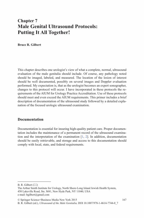
Fig. 2 Left testicular measurements with the split screen: longitudinal view on left and transverse view on right
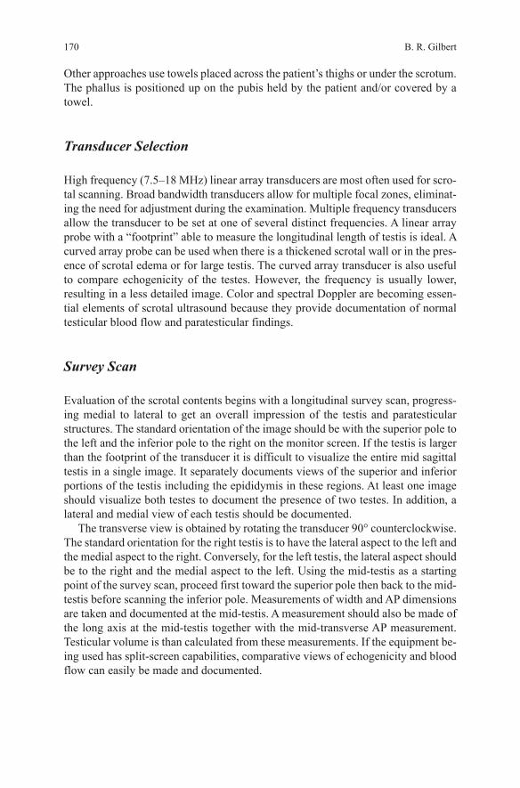
Fig. 3 Right testicular measurements with the split screen: longitudinal view on left and transverse view on the right of the screen
3. Left testicular measurements with the split screen: longitudinal view on left and transverse view on right (Fig. 2)
4. Video clip of survey scan of the right testicle (longitudinal and transverse)5. Right testicular measurements with the split screen: longitudinal view on left and
transverse view on the right of the screen (Fig. 3)6. Skin thickness measured (if abnormal)

1737 Male Genital Ultrasound Protocols: Putting It All Together!
Fig. 4 Epididymis #1: epididymal head, right and left side, split screen: right testis on left of screen and left testis on right of screen
Split Screen (laterality is when looking at screen)
7. EPIDIDYMIS #1: epididymal head, right and left side, split screen: right testis on left of screen and left testis on right of screen (Fig. 4)
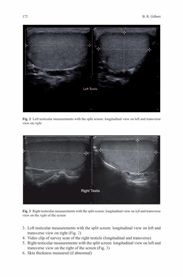
8. EPIDIDYMIS #2: Epididymal body, right and left side, split screen: right epidid-ymal body on left of screen and left epididymal body on right of screen (Fig. 5)
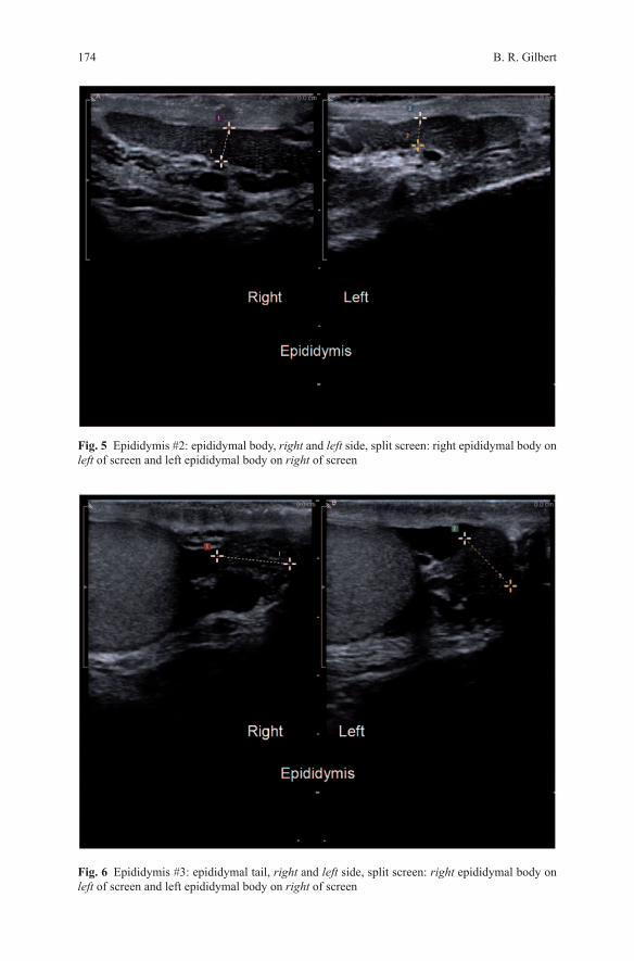
9. EPIDIDYMIS #3: Epididymal tail, right and left side, split screen: right epididy-mal body on left of screen and left epididymal body on right of screen (Fig. 6)
10. Lateral view of the left and right testis: right testis on left of screen and left testis on right of screen (Fig. 7)
11. Medial view of the left and right testis: right testis on left of screen and left testis on right of screen (Fig. 8)
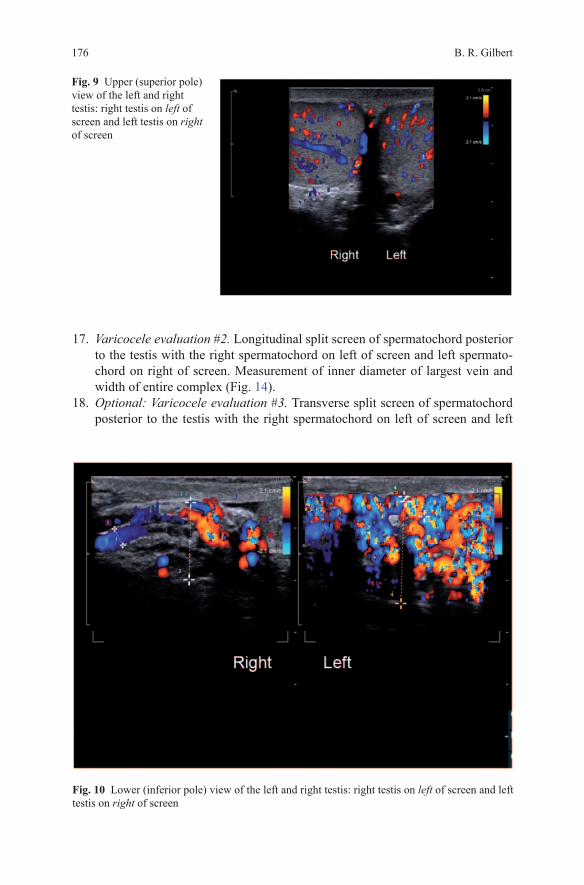
12. Upper (superior pole) view of the left and right testis: right testis on left of screen and left testis on right of screen (Fig. 9)
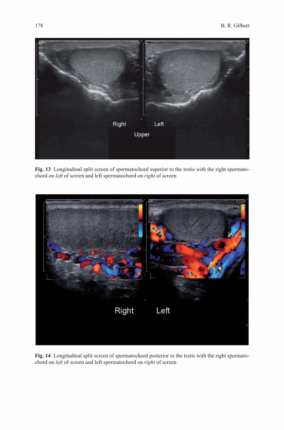
13. Lower (inferior pole) view of the left and right testis: right testis on left of screen and left testis on right of screen (Fig. 10)
Color Doppler
14. Intratesticular blood flow pattern. Split screen of longitudinal view of both testes with the right testis on left of screen and left testis on right of screen (Fig. 11).
174 B. R. Gilbert
Fig. 6 Epididymis #3: epididymal tail, right and left side, split screen: right epididymal body on left of screen and left epididymal body on right of screen
Fig. 5 Epididymis #2: epididymal body, right and left side, split screen: right epididymal body on left of screen and left epididymal body on right of screen

1757 Male Genital Ultrasound Protocols: Putting It All Together!
15. A single screen transverse view of both testes for comparative intratesticular blood flow (Fig. 12).
16. Varicocele evaluation #1. Longitudinal split screen of spermatochord superior to the testis with the right spermatochord on left of screen and left spermato-chord on right of screen. Measurement of inner diameter of largest vein and width of entire complex (Fig. 13).
Fig. 7 Lateral view of the left and right testis: right testis on left of screen and left testis on right of screen
Fig. 8 Medial view of the left and right testis: right testis on left of screen and left testis on right of screen
B. R. Gilbert176
Fig. 9 Upper (superior pole) view of the left and right testis: right testis on left of screen and left testis on right of screen
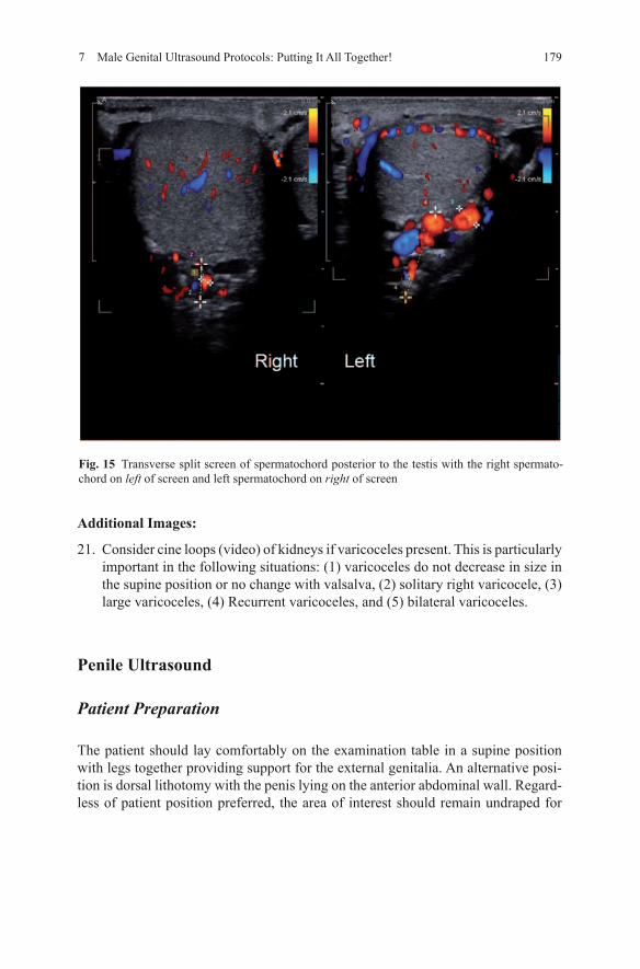
17. Varicocele evaluation #2. Longitudinal split screen of spermatochord posterior to the testis with the right spermatochord on left of screen and left spermato-chord on right of screen. Measurement of inner diameter of largest vein and width of entire complex (Fig. 14).
18. Optional: Varicocele evaluation #3. Transverse split screen of spermatochord posterior to the testis with the right spermatochord on left of screen and left
Fig. 10 Lower (inferior pole) view of the left and right testis: right testis on left of screen and left testis on right of screen

1777 Male Genital Ultrasound Protocols: Putting It All Together!
spermatochord on right of screen. Measurement of inner diameter of largest vein and width of entire complex (Fig. 15).
Spectral Doppler
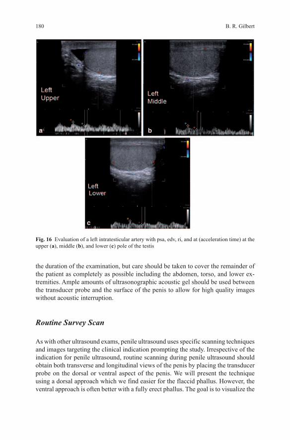
19. Evaluate a left intratesticular artery with PSA, EDV, RI, and AT (acceleration time) at the upper, middle, and lower pole of the testis (Fig. 16a–c).
20. Evaluate a right intratesticular artery with PSA, EDV, RI, and AT (acceleration time) at the upper, middle, and lower pole of the testis (Fig. 17a–c)
Fig. 11 Split screen of longitudinal view of both testes with the right testis on left of screen and left testis on right of screen
Fig. 12 A single screen transverse view of both testes for comparative intratesticular blood flow
B. R. Gilbert178
Fig. 13 Longitudinal split screen of spermatochord superior to the testis with the right spermato-chord on left of screen and left spermatochord on right of screen
Fig. 14 Longitudinal split screen of spermatochord posterior to the testis with the right spermato-chord on left of screen and left spermatochord on right of screen
1797 Male Genital Ultrasound Protocols: Putting It All Together!
Additional Images:
21. Consider cine loops (video) of kidneys if varicoceles present. This is particularly important in the following situations: (1) varicoceles do not decrease in size in the supine position or no change with valsalva, (2) solitary right varicocele, (3) large varicoceles, (4) Recurrent varicoceles, and (5) bilateral varicoceles.
Penile Ultrasound
Patient Preparation
The patient should lay comfortably on the examination table in a supine position with legs together providing support for the external genitalia. An alternative posi-tion is dorsal lithotomy with the penis lying on the anterior abdominal wall. Regard-less of patient position preferred, the area of interest should remain undraped for
Fig. 15 Transverse split screen of spermatochord posterior to the testis with the right spermato-chord on left of screen and left spermatochord on right of screen
B. R. Gilbert180
the duration of the examination, but care should be taken to cover the remainder of the patient as completely as possible including the abdomen, torso, and lower ex-tremities. Ample amounts of ultrasonographic acoustic gel should be used between the transducer probe and the surface of the penis to allow for high quality images without acoustic interruption.
Routine Survey Scan
As with other ultrasound exams, penile ultrasound uses specific scanning techniques and images targeting the clinical indication prompting the study. Irrespective of the indication for penile ultrasound, routine scanning during penile ultrasound should obtain both transverse and longitudinal views of the penis by placing the transducer probe on the dorsal or ventral aspect of the penis. We will present the technique using a dorsal approach which we find easier for the flaccid phallus. However, the ventral approach is often better with a fully erect phallus. The goal is to visualize the
Fig. 16 Evaluation of a left intratesticular artery with psa, edv, ri, and at (acceleration time) at the upper (a), middle (b), and lower (c) pole of the testis

1817 Male Genital Ultrasound Protocols: Putting It All Together!
cross-sectional view of the two corpora cavernosa dorsally and the corpus spongio-sum ventrally at different points along the length of the penis from the base of the penile shaft scanning distally toward the glans penis.
The corpora cavernosa appear dorsally, as two homogeneously hypoechoic cir-cular structures, each surrounded by a thin (usually less than 2 mm) hyperechoic layer representing the tunica albuginea that envelops the corpora. The corpus spon-giosum is a ventrally located circular structure with homogeneous echotexture, usually more echogenic than the corpora cavernosa. It is well visualized by placing the ultrasound transducer probe on either the dorsal or ventral aspect of the penis, however, it is easily compressible so minimal pressure should be maintained while scanning. For routine anatomic scanning of the penis with ultrasound, all three cor-pora can be sufficiently viewed from a single dorsal aspect obtained image of the penile shaft. A survey scan is first performed prior to obtaining static images at the proximal (base), mid-portion, and distal (tip) of the corpora cavernosal bodies for documentation. The value of the survey scan cannot be over stated. It often provides the prospective that is necessary to assure absence of coexisting pathology. In ad-
Fig. 17 Evaluation of a right intratesticular artery with psa, edv, ri, and at (acceleration time) at the upper (a), middle (b), and lower (c) pole of the testis

B. R. Gilbert182
dition, a careful survey scan of the phallus will identify abnormalities of the caver-nosal vessels, calcified plaques as well as abnormalities of the spongiosa tissue. All abnormalities should be documented with appropriate measurements if applicable, in static images.
Static images recommended as representative views of this initial surveying scan are: the transverse view at the base of the penile shaft, at the mid-shaft and at the distal shaft just proximal to the corona of the glans penis. Each image shows transverse sections of all three corporal bodies. Orientation by convention is for the right corporal body to be on the left side of the display while the left corporal body is located on the right side of the display. Our preference when viewing a longitu-dinal projection is to use a split screen view to compare the right and left corporal bodies with measurements of the cavernosal artery diameter taken in this view. We keep the orientation constant, with the projection of the right corporal body on the left side of the display while the left corporal body is located on the right side of the display. Either a dorsal or ventral approach can be used as preferred by the sonogra-pher. A flaccid phallus is often best visualized by the dorsal approach while an erect phallus by the ventral approach. We have found that imaging of the urethral wall is best performed in the erect phallus after pharmacostimulation and fill the distal ure-thra by placement of a sterile water soluble gel. We also use a silicone constriction ring around the base of the phallus to restrict loss of gel into the bladder.
Penile Ultrasound Protocol
Noted on Report
Indication for Procedure (Diagnosis code should be included to document medical necessity)
Transducer: 12–18 MHz linear array transducer with small footprintReport signed by PhysicianPlease note: if all components of the exam are not seen then the report should
document that that component was “Not Seen” and why
Baseline Study
• Longitudinal and transverse survey scan of the phallus with video clips. This should include views of both corpora cavernosa and corpora spongiosum
• Split screen base (proximal), mid and distal view of phallus in transverse plane. This should include views of both corpora cavernosa and corpora spongiosum (Figs. 18 and 19a, b).
• Measure height and width of each corpora in Figs. 18 and 19a, b.

1837 Male Genital Ultrasound Protocols: Putting It All Together!
Fig. 18 Split screen base (proximal), mid and distal view of phallus in transverse plane
Fig. 19 Split screen base (proximal), mid and distal view of phallus in transverse plane

B. R. Gilbert184
Fig. 20 Split screen longitudinal views of both corpora cavernosa and corpora spongiosum
• Split screen longitudinal views of both corpora cavernosa and corpora spon-giosum. This should include views of left and right corpora cavernosal artery (Fig. 20).
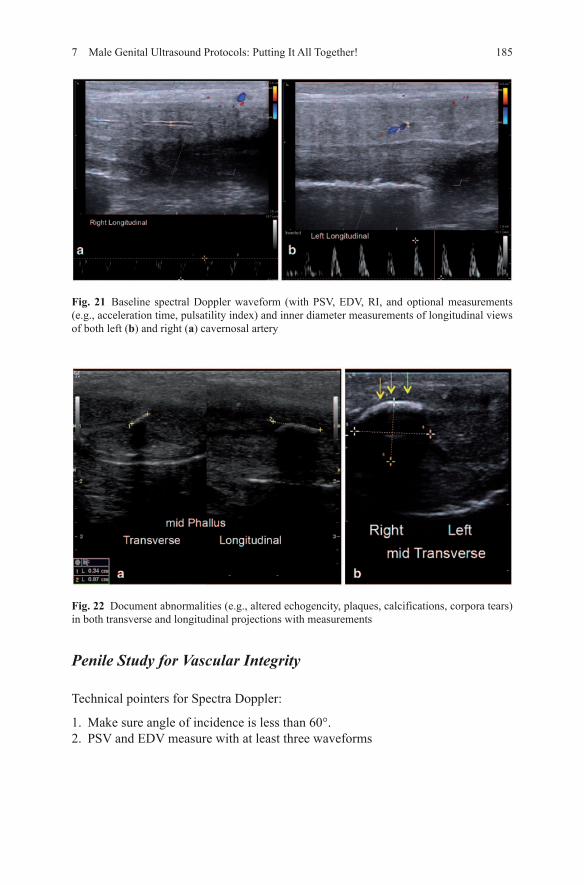
• Baseline spectral Doppler waveform (with PSV, EDV, RI, and optional measure-ments (e.g., acceleration time, pulsatility index) and inner diameter measure-ments of longitudinal views of both Left and Right Cavernosal Artery Fig. 21a, b.
• Document abnormalities (e.g., altered echogencity, plaques, calcifications, cor-pora tears) in both transverse and longitudinal projections with measurements (Figs. 22a, b and 23).
1857 Male Genital Ultrasound Protocols: Putting It All Together!
Fig. 22 Document abnormalities (e.g., altered echogencity, plaques, calcifications, corpora tears) in both transverse and longitudinal projections with measurements
Fig. 21 Baseline spectral Doppler waveform (with PSV, EDV, RI, and optional measurements (e.g., acceleration time, pulsatility index) and inner diameter measurements of longitudinal views of both left (b) and right (a) cavernosal artery
Penile Study for Vascular Integrity
Technical pointers for Spectra Doppler:
1. Make sure angle of incidence is less than 60°.2. PSV and EDV measure with at least three waveforms
B. R. Gilbert186
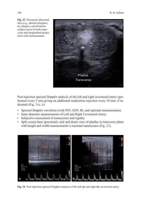
Post-injection spectral Doppler analysis of the left and right cavernosal artery (per-formed every 5 min giving an additional medication injection every 10 min, if in-dicated) (Fig. 24a, b):
• Spectral Doppler waveform (with PSV, EDV, RI, and optional measurements)• Inner diameter measurements of Left and Right Cavernosal Artery• Subjective assessment of tumescence and rigidity• Split screen base (proximal), mid and distal view of phallus in transverse plane
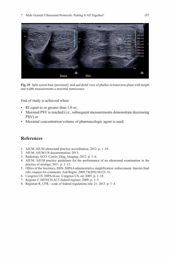
with height and width measurements a maximal tumescence (Fig. 25).
Fig. 24 Post-injection spectral Doppler analysis of the left (a) and right (b) cavernosal artery
Fig. 23 Document abnormal-ities (e.g., altered echogenc-ity, plaques, calcifications, corpora tears) in both trans-verse and longitudinal projec-tions with measurements
1877 Male Genital Ultrasound Protocols: Putting It All Together!
End of study is achieved when:
• RI equal to or greater than 1.0 or,• Maximal PSV is reached (i.e., subsequent measurements demonstrate decreasing
PSV) or• Maximal concentration/volume of pharmacologic agent is used.
References
1. AIUM. AIUM ultrasound practice accreditation; 2012. p. 1–34.2. AIUM. AIUM US documentation; 2013.3. Radiology ACO. Comm_Diag_Imaging; 2012. p. 1–6.4. AIUM. AIUM practice guidelines for the performance of an ultrasound examination in the
practice of urology; 2011. p. 1–12.5. Office of the Secretary, HHS. HIPAA administrative simplification: enforcement. Interim final
rule; request for comments. Fed Regist. 2009;74(209):56123–31.6. Congress US. HIPAALaw. Congress US, ed; 2005. p. 1–18.7. Register F. HITECH ACT federal register; 2009. p. 1–5.8. Registrar R. CFR—code of federal regulations title 21; 2013. p. 1–4.
Fig. 25 Split screen base (proximal), mid and distal view of phallus in transverse plane with height and width measurements a maximal tumescence