management plan 2011 high voltage … - management...management plan 2011 – high voltage...
TRANSCRIPT

ABN 85 082 464 622
MANAGEMENT P LAN 2011
HIGH VOLTAGE REGULATORS DOCUMENT NUMBER: NW#-30161495-V2 DATE: 8 MAY 2011
Management Plan 2011 – High Voltage Regulators
NW-#30161495-v2-Management_Plan_2011__High_Voltage_Regulators.DOC
Page 2 of 21
This page is intentionally blank.
Management Plan 2011 – High Voltage Regulators
NW-#30161495-v2-Management_Plan_2011__High_Voltage_Regulators.DOC
Page 3 of 21
TABLE OF CONTENTS 1. Purpose .................................................................................................... 4 2. Strategy .................................................................................................... 4 3. Scope ....................................................................................................... 4 4. Description of the Assets .......................................................................... 4
4.1 High Voltage Regulators .................................................................... 4 4.2 Earthing Systems .............................................................................. 7 4.3 Enclosures ......................................................................................... 8
5. Age Profile ................................................................................................ 8 6. Factors Influencing Asset Management Strategies ................................. 10
6.1 Minimising Cost of Supply to the Customer ..................................... 10 6.2 Maintaining Network Performance ................................................... 10 6.3 Managing Business Operating Risks ............................................... 10 6.4 Complying with Regulatory, Contractual and Legal Responsibilities 10
7. Specific Issues and Management Plan ................................................... 11 7.1 Treatment Trade-offs ....................................................................... 11 7.2 Preventative Maintenance and Asset Repair ................................... 11 7.3 Asset Replacement.......................................................................... 14 7.4 Oil Containment ............................................................................... 15 7.5 Open-Delta Operational Issue ......................................................... 16 7.6 Standardisation of Types ................................................................. 17 7.7 Standardisation of Sizes .................................................................. 17 7.8 Standardisation of Mounting Arrangements ..................................... 18
8. Review of Historical Practices ................................................................. 18 9. Proposed OPEX Plan ............................................................................. 18 10. Proposed CAPEX Plan........................................................................ 19 11. CAPEX–OPEX Trade Offs .................................................................. 20 12. Asset Management Information .......................................................... 20 13. Responsibilities ................................................................................... 21 14. References .......................................................................................... 21 REV NO.
DATE REVISION DESCRIPTION APPROVALS
0 16 Feb 2011 Original Issue. (NW#-30161495-V1A). Based on Asset Management Plan 2007 - Regulators (NW10219870).
Prepared by SG Reviewed by GS Approved by AD
1 8 May 2011 Updated with comments from EY. (NW#-30161495-V2).
Prepared by ST Reviewed FP Approved by AD
Management Plan 2011 – High Voltage Regulators
NW-#30161495-v2-Management_Plan_2011__High_Voltage_Regulators.DOC
Page 4 of 21
1. PURPOSE The purpose of this document is to describe for High Voltage Regulators and related assets:
• Aurora’s ap proach t o as set management, as r eflected t hrough i ts legislative and r egulatory obl igations a nd N etwork M anagement Strategy;
• The key projects and pr ograms underpinning its activities for the period 2012/13 to –2016/17; and
• Forecast C APEX an d O PEX, i ncluding t he bas is upon w hich t hese forecasts are derived.
2. STRATEGY The objective of the Network Management Strategy is:
To minimise cost of supply to the customer whilst:
a. Maintaining network performance; b. Managing business operating risks; and c. Complying w ith r egulatory, c ontractual and l egal
responsibilities.
3. SCOPE This d ocument c overs hi gh v oltage ( HV) regulators and t heir associated enclosures and earthing systems.
4. DESCRIPTION OF THE ASSETS The assets covered by the High Voltage Regulator Thread and Management Plan are: 1. High Voltage Regulators: to maintain acceptable voltage levels along
high voltage feeders 2. Earthing System: to ensure personnel and public safety and to ensure
correct operation of protection equipment; and 3. Enclosures: to provide a s afe and s ecure l ocation for hi gh v oltage
regulator equipment. The following as sets ar e not c overed un der t he H igh V oltage R egulator thread:
• Connecting overhead lines or cables; and • Capacitor banks. 4.1 High Voltage Regula tors High voltage regulators are installed at various locations along HV feeders to maintain voltage levels w ithin the distribution network to industry acceptable standards. HV r egulators ar e g enerally l ocated on r ural 11 k V and 2 2 kV feeders according t o t he l oad and l ength o f t hese feeders, w ith s everal i nstalled i n rural zone substations.

Management Plan 2011 – High Voltage Regulators
NW-#30161495-v2-Management_Plan_2011__High_Voltage_Regulators.DOC
Page 5 of 21
HV regulators can be split into two groups: 1. Single pha se uni ts: usually pol e mounted i n an op en-delta
configuration (two tanks), but may also be ground mounted; and 2. Three phase units: typically older units that are ground mounted within
a fenced enclosure. Table 1 lists the different types of HV regulators installed in Aurora’s system that were identified in a 2009 audit (reference 1). Table 1: HV regulators installed in Aurora's distribution system
Regulator type
Manufacturer Mounting Voltage (kV)
Size Installation Period
Number of Sites
Single Phase
Regulators
Cooper Pole 11 100 2000 to present
1
150 2000 to present
1
200 2000 to present
4
22 100 2000 to present
4
150 2000 to present
1
200 2000 to present
18
Ground 22 300 2000 to present
1

Management Plan 2011 – High Voltage Regulators
NW-#30161495-v2-Management_Plan_2011__High_Voltage_Regulators.DOC
Page 6 of 21
Regulator type
Manufacturer Mounting Voltage (kV)
Size Installation Period
Number of Sites
Three Phase
Regulators
Crompton Parkinson
Ground 11 52 1979 2
Wilson/ Ferranti
Ground 11 52 1978 1
105 1966 to 1998 2
157 1980 to 1982 3
262 1976 to 1978 4
22 52 1983 to 1986 2
80 1982 to 1988 5
131 1976 to 1984 7
ABB Ground 22 131 1993 to 1999 8
197 1995 to 1999 2
262 1998 1
English Electric
Ground 11 52 1978 1
Tyree Ground 22 79 1997 1
131 1982 to 1984 2
Wilson/ Fuller Ground 22 52 1983 to 1999 2
Figure 1 and Figure 2 show typical installations for three phase regulators and pole-mounted single phase open-delta regulators.

Management Plan 2011 – High Voltage Regulators
NW-#30161495-v2-Management_Plan_2011__High_Voltage_Regulators.DOC
Page 7 of 21
Figure 1: Typical Three Phase Regulator
Figure 2: Typical Pole-Mounted Single Phase Open-Delta Regulator
4.2 Earth ing Sys tems The integrity of the earthing system is essential for maintaining personnel and public safety and for the correct operation of protection equipment. The fault level, pr otection c learing t ime an d s ite s oil r esistivity dictate t he extent o f earthing required.

Management Plan 2011 – High Voltage Regulators
NW-#30161495-v2-Management_Plan_2011__High_Voltage_Regulators.DOC
Page 8 of 21
The earthing system for ground mounted regulator installations is typically a copper ear th g rid, pos sibly w ith as sociated earth pi ns. All m etallic components of the installation including the wire fence enclosure and lightning protection are connected to the earthing system. The earthing system for a pole-mounted r egulator i nstallation i s t ypically a s eries o f ear th r ods dr iven into the ground and connected by copper conductor. The difference between the two earthing systems is due to the location of the operator w hen oper ating a r egulator s ite. I n g round-mounted s ites, the operator is on t he ground and may be ex posed to step and t ouch potentials, whilst pol e m ounted regulators ar e operated from a l adder, s ignificantly reducing the exposure to step and touch potentials. 4.3 Enclos ures Ground mounted r egulator s ites ar e s urrounded by a c hain wire f ence enclosure t opped w ith b arbed w ire. The pur pose o f t he e nclosure i s t o provide a secure location for the equipment and to provide for public safety. A possum guard and warning s igns are al so installed on the fence. T ypically there are two gates installed in the enclosure fence. At some ground-mounted sites, oil containment is provided to contain the oil in the event of loss of oil from the regulator unit. There is no oil containment at pole-mounted sites. Typically t he pol e-mounted s ites are m ounted at a h eight t o pr event publ ic access and pos sum guards ar e i nstalled on t he pol es t o pr event w ildlife access, with no requirement for an enclosure.
5. AGE PROFILE The age profile data for HV regulators was compiled using data from a 2009 audit (reference 1). The manufacture year of the assets was used to calculate the age of the asset, where known. Otherwise, the installation year was used as a proxy.
Management Plan 2011 – High Voltage Regulators
NW-#30161495-v2-Management_Plan_2011__High_Voltage_Regulators.DOC
Page 9 of 21
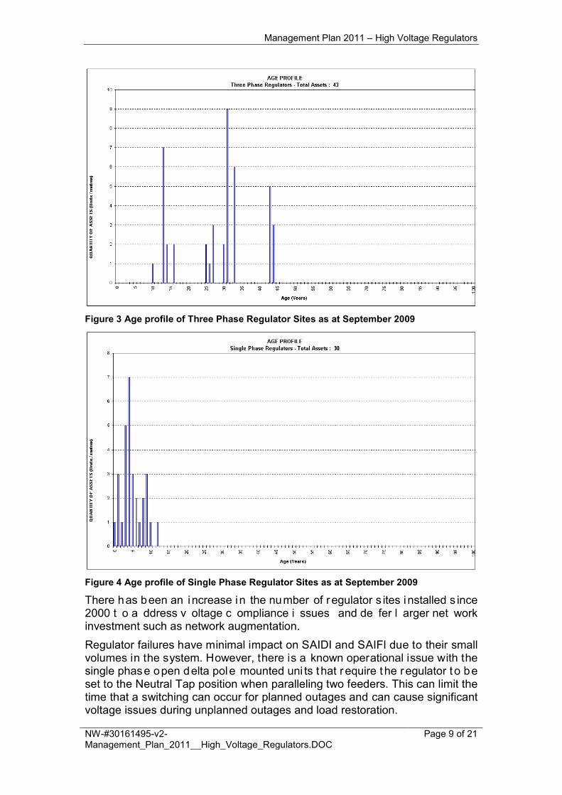
Figure 3 Age profile of Three Phase Regulator Sites as at September 2009
Figure 4 Age profile of Single Phase Regulator Sites as at September 2009
There has been an increase in the number of regulator s ites installed s ince 2000 t o a ddress v oltage c ompliance i ssues and de fer l arger net work investment such as network augmentation. Regulator failures have minimal impact on SAIDI and SAIFI due to their small volumes in the system. However, there is a known operational issue with the single phase open delta pole mounted uni ts that require the regulator t o be set to the Neutral Tap position when paralleling two feeders. This can limit the time that a switching can occur for planned outages and can cause significant voltage issues during unplanned outages and load restoration.

Management Plan 2011 – High Voltage Regulators
NW-#30161495-v2-Management_Plan_2011__High_Voltage_Regulators.DOC
Page 10 of 21
6. FACTORS INFLUENCING ASSET MANAGEMENT STRATEGIES
The pr inciple factors influencing asset management s trategies are c lassified as per objectives set out in Section 2. 6.1 Minimis ing Cos t of Supply to the Cus tomer
• Ensuring c ost e ffective t rade-offs ar e m ade bet ween pr o-active and reactive maintenance practices;
• Maintenance activities cost effectively ensure a reasonable service life is achieved from the asset; and
• Capturing ad equate i nformation on the as sets t o facilitate i nformed decision making.
6.2 Mainta in ing Ne twork Performance
• As f ailure o f t his as set c lass g enerally i mpact a l arge num ber o f customers and loads, it is crucial to maintain in-service failures to a very low level; and
• Ensuring the general operational condition of the assets is maintained to an acceptable level to ensure reliable function of the regulators and d o not supply non-compliant voltages to the customers.
6.3 Managing Bus ines s Opera ting Ris ks
• Ensuring t he as sets p erform r eliably and do not s upply non -compliant voltage to consumers;
• Ensuring adequate security is maintained to restrict unauthorised access to Aurora’s assets; and
• Ensuring a ll r isks a re identified and have adequate management plans integrated into the business’ practices.
6.4 Complying with Regula tory, Con trac tua l and Lega l Res pons ib ilitie s
• Ensuring adequate monitoring and inspection activities cover legislative compliance obligations and safety risks.
The following i s a br ief description o f t he s pecific r egulatory obl igations directly influencing Aurora’s management of HV regulators. 6.4.1 Changes to the Occupational Licensing Act 2005 Changes to the Occupational Licensing Act 2005 that became effective on 19 January 2009 r equire Aurora t o b e c ompliant w ith AS2067 Substations a nd high voltage installations exceeding 1 kV a.c. (reference 2) in the construction and operation of its distribution network. 6.4.2 Polychlorinated Biphenyls (PCBs) Aurora manages P CBs i n ac cordance w ith A urora’s P rocedure E M-M09 Management of PCB’s, which reflects the requirements of the Australian and New Z ealand E nvironment and C onservation C ouncil (ANZECC) Polychlorinated Biphenyls Management Plan (reference 3). Both plans satisfy the legislative requirements of the TAS Environmental Protection & Pollution
Management Plan 2011 – High Voltage Regulators
NW-#30161495-v2-Management_Plan_2011__High_Voltage_Regulators.DOC
Page 11 of 21
Act 19 94 and t he National E nvironment P rotection C ouncil A ct 19 94 (references 4 and 5). Polychlorinated bi phenyls (PCBs) were used i n t ransformers and capacitors amongst other things from the 1930s to the 1970s. However, they were shown to be toxic and carcinogenic and have been banned in Australia in the 1970s.
7. SPECIFIC ISSUES AND MANAGEMENT P LAN 7.1 Trea tment Trade-offs 7.1.1 Preventative versus Reactive Maintenance There i s a f undamental r equirement for A urora t o per iodically i nspect t he assets to ensure t heir phy sical s tate a nd condition d oes no t r epresent a hazard t o t he p ublic. O ther t han v isiting t he as sets, there i s no ot her economic solution to satisfy this requirement. Preventative maintenance of the tap changer units is required as failure of the units c an r esult i n s erious or c atastrophic damage, es pecially i n t he ol der three p hase u nits. J amming of t he m echanism c an r esult i n no n-compliant voltages t o c ustomers s o a bas ic l evel of pr eventative m aintenance i s required, despite the reliability of the modern single phase units. 7.1.2 Refurbishment Where H V r egulators ar e r emoved from t he network i n g ood operating condition by ac tivities s uch as c apacity a nd p ower q uality dr ivers, t hese assets ar e as sessed for r edeployment back i nto t he n etwork w here s uch refurbishment is deemed to be required and an economic proposition. 7.1.3 Planned versus Reactive Replacement Regulators ar e a n e ssential el ement i n t he n etwork i nfrastructure t hat generally do not have redundant or alternate elements in the system design. To minimise consumer disruption for extended per iods and maintain system voltages within required bounds, reactive replacement is avoided. 7.1.4 Non Network Solutions Regulators are generally installed as a cost effective alternative to upgrading other system assets. 7.2 Preventa tive Main tenance and As s e t Repa ir 7.2.1 Three Phase Regulator Inspection A monthly load and operational check is conducted on three phase regulators to c apture l oad i nformation and c heck t he units are t apping c orrectly. Historically, three phase regulators have exhibited the following failure modes: 1. Contactors sticking – the relays that pass the motor current during a tap
change s ometimes g et s tuck c ausing t he t ap c hanger t o r un aw ay t o
CONFIDENTIAL

Management Plan 2011 – High Voltage Regulators
NW-#30161495-v2-Management_Plan_2011__High_Voltage_Regulators.DOC
Page 12 of 21
either t op or bottom t ap, r esulting i n unac ceptable v oltages f or downstream customers
2. Blown resistors in the timing boards (Wilson/Ferranti) 3. Burnt out timing boards (Wilson/Ferranti) 4. Faulty A utomatic V oltage R elay ( AVR) f or ol der t ype g round mounted
units 5. Water g etting i nto t he c ontrol c ubicle c ausing s horting pr oblems
(especially on the ABB units); and 6. Springs and o ther parts hav e c ome adr ift especially on t he br aking
systems. All of these failure modes result in incorrect tapping of the units and ultimately voltage problems on the system. 7.2.2 Operational Checks and Asset Inspections Quarterly operational checks and asset i nspections are conducted on ev ery ground mounted regulator site. The operational checks and asset inspections consist of: 1. Load and tap information check: to collect load data; 2. Operational check: to ensure the unit is tapping properly; and 3. Asset inspection: to inspect the asset condition. This i nspection i s c onducted i n c onjunction with C ivil Maintenance ( section 7.2.3). 7.2.3 Civil Maintenance Civil maintenance of ground mounted regulator sites is conducted quarterly to address environmental, s afety and s ecurity i ssues and u ndertake s ite maintenance t asks s uch as w eed s praying and pai nting as r equired. T he frequency is based on Aurora’s previous experience to make sure that s ites are s afe an d c lean. This m aintenance i s c onducted i n c onjunction w ith t he Operational Checks and Asset Inspections (section 7.2.2) 7.2.4 Routine Mechanical Maintenance Routine mechanical m aintenance i s r equired t o i nspect t he mechanical components of the tap changer. Over time the tap changer contacts corrode due to normal operation and the insulating oi l develops a b uild up of carbon and foreign par ticles, reducing i ts di electric s trength, cooling pr operties an d arc-quenching ability. At r outine full m echanical m aintenance t he tap c hanger c ontacts and o ther mechanical parts are inspected and replaced if required and the insulating oil is replaced. The routine mechanical maintenance for three phase regulators is conducted every f our y ears as per t he m anufacturer’s r ecommendations and t he performance o f t he e quipment. The maintenance i s per formed o n s ite a nd requires de-energising of the unit. No transportation to a workshop is required. The routine full mechanical maintenance for s ingle-phase units is conducted every ten years or 100,000 tapping operations (whichever occurs first), as per
Management Plan 2011 – High Voltage Regulators
NW-#30161495-v2-Management_Plan_2011__High_Voltage_Regulators.DOC
Page 13 of 21
the m anufacturer’s recommendations. T he m aintenance requires the uni t t o be removed from the system and transported to workshop for full mechanical maintenance. T hus, to per form t he m aintenance w ithout i mpacting on customer pow er q uality, r eplacement uni ts are r equired t o be i nstalled a nd commissioned at t he t ime t he ol d units ar e r emoved from s ite for maintenance. 7.2.5 Single Phase Regulators – Tap Position Indicators To address the issue of older style tap position indicators on the single-phase regulators suffering from corrosion and water ingress, it is proposed to replace the t ap p osition i ndicators dur ing r outine m echanical m aintenance (section 7.2.4). Whilst the tap position indicators can be replaced on site, it is more efficient to address this issue as part of the routine mechanical maintenance, as on-site replacement requires the units to be de-energised. 7.2.6 Single Phase Regulators – Tap Changer Motor Drive Capacitor Single phase regulators were introduced into the distribution system in 2000. Aurora has one recorded incident in 2006 were two tanks failed in service due to faulty tap changer motor drive capacitors. In early models of the single phase regulators, installed with a CL-5 controller, the motor dr ive capacitor i s l ocated w ithin the regulator t ank. Thus, a faulty motor drive capacitor requires the unit to be removed from site and de-tanked to replace the capacitor. Knowing that this failure mode exists in earlier models, it is desirable for future models to have the motor drive capacitor located outside the tank to remove the need to de-tank the regulator for capacitor failures. The manufacturer has advised that i t is possible to relocate the tap changer motor dr ive capacitor f rom inside the tank to the control cubicle. Thus, i t i s planned t o r elocate t he t ap c hanger m otor dr ive c apacitor t o the c ontrol cubicle on all units with an internal capacitor as part of the routine mechanical maintenance (section 7.2.4). 7.2.7 Single Phase Regulator Oil Checks Single phas e H V r egulators h ave an oi l t est c onducted ev ery f ive y ears t o check t he i ntegrity of t he i nsulating oi l bet ween r outine mechanical maintenance because the tapping occurs in the main tank. Three phase units have separate main tank and tap changer compartments and as part of the maintenance of three phase units the oil is changed in the tap changer compartment, so there is no requirement to test the oi l between maintenance cycles. 7.2.8 Remote Control Where s hown t o b e an ec onomic proposition, r emote monitoring eq uipment will b e in stalled a t s ingle-phase unit r egulator s ites. This equipment w ill be used to monitor the voltages, currents and operation of the equipment and will be used to remotely control the regulators. From a maintenance point of view, the information gathered from each site using the remote monitoring will assist
Management Plan 2011 – High Voltage Regulators
NW-#30161495-v2-Management_Plan_2011__High_Voltage_Regulators.DOC
Page 14 of 21
in maintenance decisions, for example, if a regulator is heavily loaded or is tap changing f requently, t his s ite m ay r equire preventative m aintenance m ore frequently than others. The Network Development Team manages t his program. Remote control of older t hree ph ase r egulator sites w ill be i nvestigated o nce all s ingle phas e units have been completed. 7.2.9 Maintenance Improvements The C L-6 c ontroller, i nstalled on s ome s ingle phas e r egulators (those w ith quick-drive tap changers) has two features, which may improve single phase regulator maintenance, namely: 1. Duty Cycle Monitoring; and 2. Preventative Maintenance Tapping. It is proposed that both options of this feature be trialled at Aurora’s Training School regulator sites for further analysis before rolling it out to the entire CL-6 population. These readings can be i ncluded in the information download once the single phase units are remote controlled. Duty Cyc le Monitoring Duty c ycle m onitoring c alculates t he w orst c ase v alue of us ed l ife as a percentage for e ach arcing s urface c ontact on t he t ap c hanger bas ed on measured current, voltage, power factor and tap position. The manufacturer recommends t hat r outine m echanical maintenance be s cheduled onc e t he Duty Cycle Monitor reaches 75%. This feature m ay be used t o al low f or m ore e fficient s cheduling o f r outine mechanical m aintenance, as t he m aintenance i s s cheduled bas ed on t he estimated condition inferred from the measured duty of the tap changer rather than at set time intervals. Preventa tive Main tenance Tapping The Preventative Maintenance Tapping feature automatically operates the tap changer periodically to prevent a build-up of carbon, known as coking, on the tap changer contacts. Two Preventative Maintenance Tapping options are available: 1. Tap up once, down twice, then up once again to remove carbon from the
tap position contacts; and 2. Tap pas t t he n eutral tap pos ition by one t o r emove c arbon from t he
reverse switch contacts. 7.3 As s e t Replacement 7.3.1 Three Phase Regulator Replacement Program Due t o k nown failure m odes w ith t hree phase r egulators an d t he hi gh preventative m aintenance c osts as sociated with t hese as sets ( monthly l oad and op erational checks, f our yearly routine m echanical m aintenance, etc.), Aurora has m ade t he dec ision t o r eplace t hese uni ts as t hey f ail, r equire significant maintenance or refurbishment work.

Management Plan 2011 – High Voltage Regulators
NW-#30161495-v2-Management_Plan_2011__High_Voltage_Regulators.DOC
Page 15 of 21
Aurora proposes to replace one site each year based on the condition of the asset. Section 7.4 covers the replacement strategy in more detail. 7.3.2 Single Phase Regulators – Rusted Tanks The current po pulation o f s ingle p hase r egulators w ere s upplied w ith m ild steel tanks and after less than 10 years in service several of these units are showing severe signs of rusting. To address the i ssue o f r usted t anks on t he s ingle ph ase r egulator uni ts, Aurora investigated remediation options including:
• Replacing the existing tanks with stainless steel tanks as part of routine mechanical maintenance
• Repairing the existing tanks as part of routine mechanical maintenance • Repairing and g alvanising t he ex isting t anks a s pa rt of r outine
mechanical maintenance. The c ost for a new s teel t ank w as f ound t o be ap proximately $22, 000 pe r tank. The c ost o f r epairing o f t he t ank and pr oviding pr otective c oating of epox y paints suitable for all kind of hostile environmental conditions (C4) was found to be approximately $3000 per tank. The option of repairing and galvanising the existing tanks was discounted, as there was no local supplier able to galvanise a tank of this size. Based on this information, all existing tanks will be repaired and treated with a protective coating as part of their routine full mechanical maintenance. The m anufacturer o f t he single ph ase regulators has an All 304 S tainless Steel tank option available. A ll new single phase regulators will be supplied with All 304 Stainless Steel tanks. 7.3.3 Environmental Issues
Environmentally s ensitive s ites will be r elocated or c onverted i nto a g round mounted site with single phase regulators and appropriate oil bunding. Aurora proposes to address one site each year. 7.4 Oil Conta inment AS2067 requires that every high voltage installation containing equipment with more than 500 l itres of a l iquid dielectric such as t ransformer oi l, shall have provision for containing the total volume of any possible leakage and meet the
CONFIDENTIAL

Management Plan 2011 – High Voltage Regulators
NW-#30161495-v2-Management_Plan_2011__High_Voltage_Regulators.DOC
Page 16 of 21
overall obj ectives of AS1940: T he s torage and han dling of f lammable and combustible liquids, Appendix H (reference 6). All three-phase regulators have greater than 500 litres of oil and Table 2 lists the volume of oil contained in the various sizes of single-phase regulators. Table 2: Single Phase Regulator Oil Volumes
Voltage (kV) Size (A) Oil Volume (l)
11 100 275
150 370
200 360 to 407
300 674
22 50 371
100 498 to 550
150 659
200 765
300 1213
Currently, appr oximately 30% o f g round m ounted r egulator sites hav e adequate oil containment as per AS2067 at the time of installation. 7.5 Open-Delta Opera tiona l Is s ue To d ate, al l s ingle phase r egulator s ites h ave been i nstalled i n open-delta configuration. O ne of t he adv antages o f t his c onfiguration i s t hat i t onl y requires two single phase units per site to regulate three phases. This results in significant cost savings. A limitation o f t he open-delta c onfiguration i s t hat the r egulator m ust be switched t o t he neut ral t ap pos ition w hen par alleling t wo f eeders. T his c an limit t he t ime that a p arallel c an be i n place for planned o utages and c an cause s ignificant v oltage i ssues dur ing unpl anned ou tages and l oad restoration. There are also a number o f s ites where the load is such that the regulators cannot be br ought bac k t o ne utral t ap bec ause t his w ould l ead t o unacceptable voltage drops which eventually could lead to black outs. The switching can also be labour intensive if there are a number of open-delta regulator s ites on the feeders t o be paralleled, as operators are required to visit each site to switch the units to neutral tap. Distribution O perations hav e hi ghlighted a nu mber o f r egulator s ites t hat cause frequent op erational i ssues bec ause of t heir op en-delta c onfiguration (reference 7). To address the operational l imitations o f t he open -delta c onfiguration of t he single phase regulators, a prioritised program is in place to convert open-delta sites to closed-delta configuration. The Network Development team manages this program.

Management Plan 2011 – High Voltage Regulators
NW-#30161495-v2-Management_Plan_2011__High_Voltage_Regulators.DOC
Page 17 of 21
For al l new s ites, D istribution O perations w ill be c onsulted t o c onsider t he operational impacts prior to deciding on the configuration to be installed. 7.6 Standard is a tion of Types Following the HV regulator audit in 2009, a whole of life cost comparison was conducted between three phase regulator units, open-delta single-phase units and closed-delta single- phase units (reference 8). The results of this analysis found that the whole of l ife cost for s ingle-phase units is significantly less than three phase units. Additionally, spares holdings calculations were performed following the 2009 audit ( reference 9) and t here ar e r educed s pare hol ding r equirements i f Aurora phases out three phase regulators. Thus, A urora pl ans t o r eplace all t hree-phase r egulators w ith s ingle-phase units as these u nits a re s maller and r elocate m ore e asily and r equire less maintenance and inspection. Additionally, single phase units are bi-directional and have the future ability to be remote controlled providing greater f lexibility during routine and emergency operational system management. 7.7 Standard is a tion of Sizes Table 3 summarises t he si zes o f si ngle-phase r egulator s ites w ithin t he distribution ne twork. T here i s a w ide r ange o f s ingle-phase r egulator s izes currently i n service, however 200 A uni ts account for approximately 70% o f the population. Table 3: Single phase regulator sizes within the 11 kV and 22 kV networks
Voltage kV
Capacity Population
Amps MVA
11 100 2 1
11 150 3 1
11 200 4 4
22 100 4 4
22 150 6 1
22 200 8 18
22 300 11 1
Aurora’s s trategy i s to s tandardise o n 200 A u nits t o minimise b oth maintenance spares and emergency spares, as the cost differential between 100 A, 150 A and 200 A tanks is negligible. T he larger 300 A units will be used when required. The ex isting 100 A a nd 1 50 A u nits w ill remain as part of t he r egulator population. A s these uni ts are removed from service at routine mechanical maintenance t hey w ill be r eplaced w ith a unit o f t he s ame s ize i f one i s available in the maintenance spares holding and analysis determines this i s still appropriate for this site, otherwise they will be replaced with a 200 A unit. They will be maintained and continue to be redeployed throughout the system
Management Plan 2011 – High Voltage Regulators
NW-#30161495-v2-Management_Plan_2011__High_Voltage_Regulators.DOC
Page 18 of 21
until t hey ar e n o l onger s erviceable. N o n ew 100A or 1 50A uni ts w ill be purchased. 7.8 Standard is a tion of Mounting Arrangements As a r esult of the changes to oi l containment requirements in AS 2067, pole mounting of 11 kV units greater than 200 A and al l 22 kV units is no longer feasible, as t here are no ad equate oil containment ar rangements to comply with the standard. It has al so been found t o be di fficult t o des ign a c losed-delta pole-mounted arrangement, so a decision has been made to ground mount all new regulator sites, with the exception of lightly loaded 11 kV spur lines. All n ew s ites w ill b e installed w ith t wo s ingle p hase uni ts, g round m ounted, open-delta s ites, with oi l containment arrangement having sufficient capacity for t hree t anks, w ith t he s ite des igned t o al low f uture ex pansion to c losed-delta configuration.
8. REVIEW OF HISTORICAL PRACTICES Aurora’s asset management practices on these assets have been stable for a number of years and are generally considered to be providing a well balanced trade-off between maintenance and capital expenditure. In-service failures are rare and the assets are achieving and exceeding their expected service life. Of particular c oncern ar e t he t hree phase r egulator as sets t hat ar e approaching or hav e ex ceeded t heir nor mal ex pected s ervice l ife. The deteriorating c ondition o f t he as sets i s m aking ong oing m aintenance uneconomical. Aurora has also experienced significant increase in routine maintenance costs over t he l ast f ew years due t o w ork pl ace standard s afety c ompliance t hat require two personnel to attend live sites instead of one. Standardisation o f t he installations a nd i mproved c ontrollers an d communications c apability will al low s ignificant r eduction i n i nspection and monitoring costs moving forward.
9. PROPOSED OPEX PLAN It i s proposed to continue with the current asset management practices, but with the some additional expenditure. Inspection levels on t he older units will continue at current levels as there is concern s urrounding their r eliable op eration. I ncrease i n pr oposed O PEX expenditure is attributed to the increased corrective maintenance and routine maintenance costs on these units and t he volume of new uni ts entering the system. Table 4 shows the historical operational expenditure on HV regulators and the proposed future spend. Table 4: OPEX for period between 2007/08 and 2016/17 financial years ($)
Work Program 2007/08 2008/09 2009/10 2010/11 2011/12 2012/13 2013/14 2014/15 2015/16 2016/17
Inspection 0 82,229 132,315 42,000 140,000 104,703 95,545 88,500 81,010 74,782

Management Plan 2011 – High Voltage Regulators
NW-#30161495-v2-Management_Plan_2011__High_Voltage_Regulators.DOC
Page 19 of 21
Maintenance 49,255 54,627 84,832 74,241 74,240 84,550 82,087 81,064 79,504 78,905
Repair 44,804 107,310 139,237 100,000 100,000 236,700 230,032 227,267 223,050 221,428
Actual $$ 94,059 244,167 356,383
Proposed 167,065 223,450 169,351 216,241 314,240 425,953 407,665 396,830 383,564 375,114
10. PROPOSED CAPEX PLAN The following values were obt ained using A urora’s C apex M odel ( reference 10). U sing t he es timated l ife expectancy f eature o f t he model for this as set category, t he following en velope o f r enewal i nvestment i s r equired over t he following 20 y ears t o m aintain t he asset c lass at a s table R emaining Li fe Expectancy (RLE). Figure 5 shows the out puts o f A urora’s capital ex penditure m odel f or HV regulators, t aking i nto account condition, r isk and age. The model forecasts capital investment of $1.97m over the next regulatory period.
Figure 5: Forecast CAPEX Expenditure from PB Model ($M)
Aurora’s proposed capital expenditure for the next regulatory period is $3.8m. This s pend i s g reater t han the model forecast d ue to A urora’s r isk and condition based approach to asset renewal which seeks to:
• Reduce the risk of in service failure and gain maintenance efficiencies by replacing only substandard condition three phase regulators;
• Reduce t he r isk o f A urora’s oi l f illed r egulators l ocated c lose t o waterways, dr inking water and s ensitive a reas c ausing env ironmental damage; and
• Improve t he condition of t he rusting s ingle phase t anks to achieve t he expected asset life.

Management Plan 2011 – High Voltage Regulators
NW-#30161495-v2-Management_Plan_2011__High_Voltage_Regulators.DOC
Page 20 of 21
Table 5 shows t he hi storical c apital ex penditure o n H V r egulators and t he proposed future spend. Table 5: CAPEX for period between 2007/08 and 2016/17 financial years ($)
Work Program 2007/08 2008/09 2009/10 2010/11 2011/12 2012/13 2013/14 2014/15 2015/16 2016/17
Non Demand Replacement 13,433 185,270 148,365 240,000 405,000 346,187 365,152 425,894 483,447 453,134
Specific Issues 0 0 0 0 0 346,187 344,302 343,545 342,335 341,851
Actual $$ 13,433 185,270 148,365
Proposed 287,387 177,017 140,000 240,000 405,000 692,373 709,454 769,439 825,783 794,986
11. CAPEX–OPEX TRADE OFFS The o perating ex penditure pr ograms are es sential for i dentifying assets t he require replacement for condition-based reasons. A n example of this is the inspection and routine maintenance of three phase regulator sites, which may lead to a r equirement for capital expenditure to replace the regulator due to uneconomical maintenance costs and impending asset failure. There is a p ositive relationship between these two categories in that regular inspection programs gather continuous condition information of the assets to better target asset replacements and identify any asset t rends. Maintenance and r epair ac tivities a lso de fer t he r equirement for c apital expenditure and increase the likelihood of the asset operating for as long as possible within the network. Other k ey i nteractions bet ween t he c apital ex penditure a nd oper ating expenditure exists w hen ol der eq uipment w ith hi gher m aintenance requirements ar e r eplaced w ith new eq uipment w ith l ower m aintenance requirements, such as three phase regulators with single phase regulators.
12. ASSET MANAGEMENT INFORMATION Aurora maintains r ecords o f r egulator assets t hrough t he per iodic r outine testing a nd i nspection pr ograms pr oviding t he following i nformation. The equipment details an d at tributes are predominantly r ecorded w ithin G -Tech and WASP. These b eing t he t wo i ntegrated as set m anagement s ystems, however t here ar e smaller dat a-sets i n M S Access and E xcel t hat c urrently store other information relating to the asset and its condition. Recorded information includes:
• Identification number (unique identifier); • Location / site / geographical details; • Asset / e quipment, terminations and jointing details (size, make, model,
type, rating, installed date); • Equipment attributes and operational numbering; • Operational d etails ( connectivity, pr otection and eq uipment s ettings /
ratings, etc);

Management Plan 2011 – High Voltage Regulators
NW-#30161495-v2-Management_Plan_2011__High_Voltage_Regulators.DOC
Page 21 of 21
• System performance details ( reliability, causes, power quality recorded data etc);
• System monitoring information / data (load – cyclic, maximum demand, load balance);
• Asset condition data and remaining residual life (general and limited); • Oil condition, contamination levels; • Age of asset and components, installed / refurbished date; • Age of related equipment; • Unit rates or agreed costs, i .e. inspection, t reatment refurbishment and
replacement costs; • Maintenance details / action; • Maintenance program progress; and • Maintenance history (general and limited).
13. RESPONSIBILITIES The m aintenance an d i mplementation o f t his m anagement p lan i s t he responsibility of the Asset Engineer – Substation and Underground. Approval of this management plan is the responsibility of the Group Manager – Asset Performance and Information.
14. REFERENCES 1. High Voltage Regulator Audit Review 2009 (DM # 30062708) 2. AS 2067 Substations and high voltage installations exceeding 1 kV a.c. 3. Australian an d N ew Zealand E nvironment an d C onservation C ouncil
(ANZECC) P olychlorinated B iphenyls Management P lan (Revised Edition April 2003)
4. TAS Environmental Protection & Pollution Act 1994 5. National Environment Protection Council Act 1994 6. AS1940: The s torage and ha ndling o f f lammable and c ombustible
liquids, Appendix H 7. Regulator Operational Issue – Feeder Parallel (DM # 30064060) 8. NPV Summary Sheet (DM # 30126955) 9. Spares Management Plans: Regulators (DM # 30087907) 10. PB CAPEX Model: HV Regulators (DM # 30160065)