manual & guides: anderson greenwood series 400 … · 6” type 46x 06.5612.012 .750-16 unf 2...
TRANSCRIPT

Anderson Greenwood SerieS 400 Diaphragm pilot operateD Safety relief ValVeSInstallatIon and MaIntenance InstructIons
© 2017 emerson. all rights reserved.valves.emerson.com
1 GenerAl vAlve description And stArt-up
1.1 Generalthe anderson greenwood Series 400 valve is designed for modulating action. the main valve will open at nameplate set, but only an amount proportional to the relieving capacity required. as process pressure increases, the valve will open more and be in full lift at 110% of set.
1.2 installationeither or both inlet and outlet may be standard aNSi flanges or aNSi pipe threaded connections and are to be installed in accordance with accepted piping practices.When remote pressure pickup is used the pilot supply tube is connected to a remote location rather than to the inlet neck of the valve. a block valve in the remote pilot supply line is not recommended. if one is used it must be opened before pressurizing the main valve.
noteremote pressure pickup piping must have the equivalent flow area of ⅜” tubing for lengths up to 100 feet. for lengths greater than this, consult factory.
1.3 start-upthere must be pressure at the valve inlet or at the pilot inlet/sense port for valves with remote sense to establish a differential force across the piston and “load” it in the closed piston. pressure must pass through the pilot and exert force on the top of the piston. on normal plant startup the valve loads itself as pressure increases.
Before installation these instructions must be fully read and understood
tAble of contents
1 general valve description and start-up ....... 12 main valve maintenance ............................... 23 pilot maintenance ......................................... 74 pilot adjustment .......................................... 155 Valve assembly testing................................ 216 pilot set pressure field test procedure ...... 247 Soft goods repair kits .................................. 258 pilot accessories ......................................... 269 assembly and maintenance equipment .... 26
engineering Doc. #05.9040.269 rev. l
vcioM-06019-en 17/05
the main valve uses the principle of pressurizing the top or large area of a differential area piston with line pressure to hold the piston closed up to set pressure. at set pressure, the pilot relieves, depressurizing the volume above the piston, the main valve dome, and the piston lifts permitting discharge from the main valve. as capacity relief of the system is satisfied, system pressure will begin to decrease. When it does, the pilot will actuate and direct system pressure to the main valve dome. this closes the main valve.the pilot is the nonflowing type. With the main valve open and relieving at steady pressure, no process gas or fluid flows through the pilot. When process pressure changes, the pilot actuates to change the lift of the main valve piston. During these actuations a small amount of gas or fluid from the main valve dome flows through the pilot and is discharged thru the pilot exhaust.the set pressure range is 15 psig to 740 psig.
installation and maintenance instructions for Series 400 Diaphragm pilot operated Safety relief Valves (poSrV).the intent of these instructions is to acquaint the user with the maintenance of this product.please read these instructions carefully.
Block valves are often used under safety valves to isolate them when maintenance is required. When putting the safety valve in service be sure the block valve is fully opened. if the block valve is opened after system startup, the safety valve may briefly vent before the dome gets pressurized to close the main valve seat.
2
32
32.010r.020
Anderson Greenwood SerieS 400 Diaphragm pilot operateD Safety relief ValVeSInstallatIon and MaIntenance InstructIons
2 MAin vAlve MAintenAnce
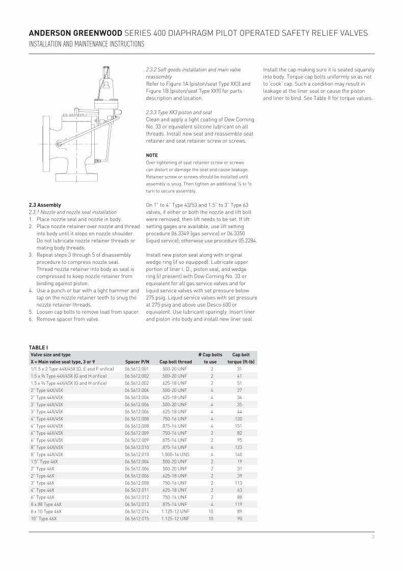
2.1 disassemblyBefore beginning disassembly, bleed off any pressure trapped in the main valve or pilot.refer to figure 1a (piston/seat type XX3) and figure 1B (piston/seat type XX9) for parts description and location.remove cap (item 17) from the body (item 1). remove the liner seal (item 6), liner (item 5) and piston (item 10). remove the soft goods from the piston. if the piston is equipped with a wedge ring (item 23), clean and retain it for use during assembly. the dipper tube (item 4) is swaged in place and no attempt should be made to remove it. the nozzle (item 3) should not be removed unless it is damaged or the nozzle seal (item 2) is leaking.
noteDo not remove lock pin and lift adjusting bolt (items 11 and 12) on valves so equipped unless nozzle is removed. this bolt controls the piston lift and hence the valve’s relieving capacity. if either or both the nozzle and lift bolt were removed, then lift must be reset following the procedure of paragraph 2.3.3 (type XX3) or paragraph 2.3.4 (type XX9).
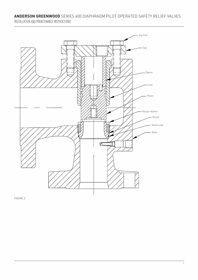
2.1.1 Nozzle and nozzle seal disassemblyrefer to figure 2 for parts description and location.1. remove lock pin and lift adjusting bolt from
piston, if applicable.2. place liner in body and piston, without seat
or seat retainer, into liner and on top of nozzle.
3. place appropriate spacer (see table i) on top of piston and then the cap over the spacer.
4. thread the appropriate number of cap bolts (see table i) into threaded holes on top of body. if two bolts are used, they should be 180° apart. When using four bolts, they should be 90° apart. always use the shortest cap bolts supplied with the valve unless all cap bolts are required. for example, the 1” type 40/50 is equipped with two 1.50” long bolts and two 1.88” long bolts but only the two 1.50” long bolts should be used. however, the 2” type 40/50 is equipped with two 1.25” long bolts and two 1.62” long bolts and all four bolts are required for nozzle installation.
5. tighten cap bolts evenly to the torque listed in table i to compress nozzle seal.
6. Use a punch or bar with a light hammer and tap on the nozzle retainer teeth to loosen the nozzle retainer. Unthread nozzle retainer approximately ½ turn.
7. loosen cap bolts to remove load from nozzle. remove components from main valve.
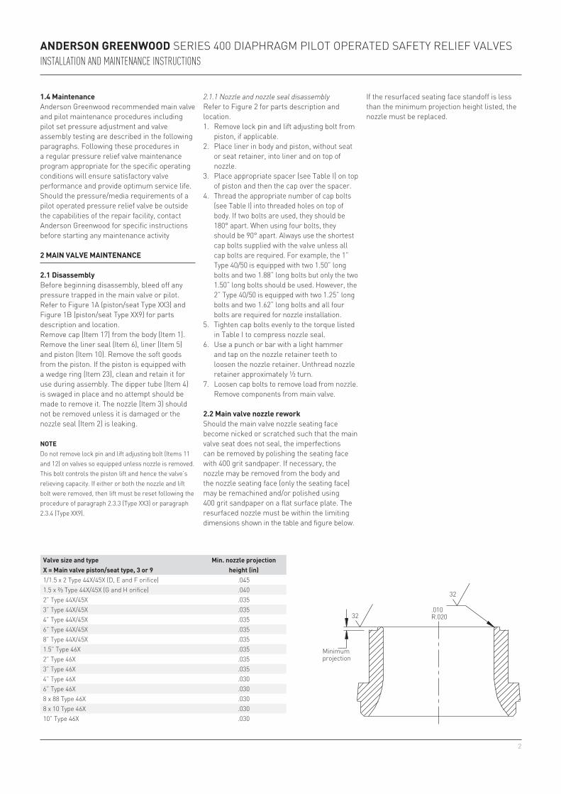
valve size and typeX = Main valve piston/seat type, 3 or 9
Min. nozzle projection height (in)
1/1.5 x 2 type 44X/45X (D, e and f orifice) .0451.5 x ⅔ type 44X/45X (g and h orifice) .0402” type 44X/45X .0353” type 44X/45X .0354” type 44X/45X .0356” type 44X/45X .0358” type 44X/45X .0351.5” type 46X .0352” type 46X .0353” type 46X .0354” type 46X .0306” type 46X .0308 x 88 type 46X .0308 x 10 type 46X .03010” type 46X .030
2.2 Main valve nozzle reworkShould the main valve nozzle seating face become nicked or scratched such that the main valve seat does not seal, the imperfections can be removed by polishing the seating face with 400 grit sandpaper. if necessary, the nozzle may be removed from the body and the nozzle seating face (only the seating face) may be remachined and/or polished using 400 grit sandpaper on a flat surface plate. the resurfaced nozzle must be within the limiting dimensions shown in the table and figure below.
minimum projection
1.4 Maintenanceanderson greenwood recommended main valve and pilot maintenance procedures including pilot set pressure adjustment and valve assembly testing are described in the following paragraphs. following these procedures in a regular pressure relief valve maintenance program appropriate for the specific operating conditions will ensure satisfactory valve performance and provide optimum service life.Should the pressure/media requirements of a pilot operated pressure relief valve be outside the capabilities of the repair facility, contact anderson greenwood for specific instructions before starting any maintenance activity
if the resurfaced seating face standoff is less than the minimum projection height listed, the nozzle must be replaced.
3
Anderson Greenwood SerieS 400 Diaphragm pilot operateD Safety relief ValVeSInstallatIon and MaIntenance InstructIons
2.3 Assembly2.3.1 Nozzle and nozzle seal installation1. place nozzle seal and nozzle in body.2. place nozzle retainer over nozzle and thread
into body until it stops on nozzle shoulder. Do not lubricate nozzle retainer threads or mating body threads.
3. repeat steps 3 through 5 of disassembly procedure to compress nozzle seal. thread nozzle retainer into body as seal is compressed to keep nozzle retainer from binding against piston.
4. Use a punch or bar with a light hammer and tap on the nozzle retainer teeth to snug the nozzle retainer threads.
5. loosen cap bolts to remove load from spacer.6. remove spacer from valve.
tAble ivalve size and typeX = Main valve seat type, 3 or 9 spacer p/n cap bolt thread
# cap bolts to use
cap bolt torque (ft·lb)
1/1.5 x 2 type 44X/45X (D, e and f orifice) 06.5612.001 .500-20 UNf 2 311.5 x ⅔ type 44X/45X (g and h orifice) 06.5612.002 .500-20 UNf 2 411.5 x ⅔ type 44X/45X (g and h orifice) 06.5612.002 .625-18 UNf 2 512” type 44X/45X 06.5612.004 .500-20 UNf 4 272” type 44X/45X 06.5612.004 .625-18 UNf 4 343” type 44X/45X 06.5612.006 .500-20 UNf 4 353” type 44X/45X 06.5612.006 .625-18 UNf 4 444” type 44X/45X 06.5612.008 .750-16 UNf 4 1304” type 44X/45X 06.5612.008 .875-14 UNf 4 1516” type 44X/45X 06.5612.009 .750-16 UNf 2 826” type 44X/45X 06.5612.009 .875-14 UNf 2 958” type 44X/45X 06.5612.010 .875-14 UNf 4 1238” type 44X/45X 06.5612.010 1.000-14 UNS 4 1401.5” type 46X 06.5612.004 .500-20 UNf 2 192” type 46X 06.5612.006 .500-20 UNf 2 312” type 46X 06.5612.006 .625-18 UNf 2 393” type 46X 06.5612.008 .750-16 UNf 2 1134” type 46X 06.5612.011 .625-18 UNf 2 636” type 46X 06.5612.012 .750-16 UNf 2 888 x 88 type 46X 06.5612.013 .875-14 UNf 4 1198 x 10 type 46X 06.5612.014 1.125-12 UNf 10 8910” type 46X 06.5612.015 1.125-12 UNf 10 90
2.3.2 Soft goods installation and main valve reassemblyrefer to figure 1a (piston/seat type XX3) and figure 1B (piston/seat type XX9) for parts description and location.
2.3.3 Type XX3 piston and seatClean and apply a light coating of Dow Corning No. 33 or equivalent silicone lubricant on all threads. install new seat and reassemble seat retainer and seat retainer screw or screws.
noteover tightening of seat retainer screw or screws can distort or damage the seat and cause leakage. retainer screw or screws should be installed until assembly is snug. then tighten an additional ¼ to ½ turn to secure assembly.
on 1” to 4” type 43/53 and 1.5” to 3” type 63 valves, if either or both the nozzle and lift bolt were removed, then lift needs to be set. if lift setting gages are available, use lift setting procedure 06.3349 (gas service) or 06.3350 (liquid service); otherwise use procedure 05.2284.
install new piston seal along with original wedge ring (if so equipped). lubricate upper portion of liner i. D., piston seal, and wedge ring (if present) with Dow Corning No. 33 or equivalent for all gas service valves and for liquid service valves with set pressure below 275 psig. liquid service valves with set pressure at 275 psig and above use Desco 600 or equivalent. Use lubricant sparingly. insert liner and piston into body and install new liner seal.
install the cap making sure it is seated squarely into body. torque cap bolts uniformly so as not to ‘cock’ cap. Such a condition may result in leakage at the liner seal or cause the piston and liner to bind. See table ii for torque values.

4
13
13
23
1
6 18 17 11 1216
29
8
4 22
3
13105
7
15 21
¼ 75/16 12⅜ 217/16 33½ 459/16 59⅝ 97¾ 130⅞ 2021 2711 ⅛ 408
Anderson Greenwood SerieS 400 Diaphragm pilot operateD Safety relief ValVeSInstallatIon and MaIntenance InstructIons
2.3.4 Type XX9 piston and seatClean and apply a light coating of Dow Corning No. 33 or equivalent silicone lubricant on all threads. Do not apply any lubricant to any of the soft goods. install new seat and reassemble seat retainer and seat retainer screw or screws.
noteover tightening of seat retainer screw or screws can distort or damage the seat and cause leakage. retainer screw or screws should be installed until assembly is snug. then tighten an additional ¼ to ½ turn to secure assembly.
on 1” to 4” type 49/59 and 1.5” to 3” type 69 valves, if either or both the nozzle and lift bolt were removed, then lift needs to be set. if lift setting gages are available, use lift setting procedure 06.3349 (gas service) or 06.3350 (liquid service); otherwise use procedure 05.2284.
item no. part name1 Body2 Nozzle seal [1]
3 Nozzle [1]
4 Dipper tube5 liner6 liner seal [2]
7 Seat [2]
8 Seat retainer9 Seat retainer screw10 piston
detail Aliquid service
detail Agas service
see detail A
notes1. field replaceable only if required.2. recommended spare parts for repair.3. Used only for liquid service.4. Not used on 6”, 8” type 443/453 and 4” and larger
type 463.
refer to Section 7.1 for soft goods repair kit part numbers.
figUre 1a - maiN ValVe443/453/463
tAble iibolt size torque value (ft·lb)
install new piston seal along with original wedge ring (if so equipped) and snap ring. insert liner and piston into body and install new liner seal.
install the cap making sure it is seated squarely into body. torque cap bolts uniformly so as not to ‘cock’ cap. Such a condition may result in leakage at the liner seal or cause the piston and liner to bind. See table ii for torque values.
item no. part name11 lift adjusting bolt [4]
12 lock pin [4]
13 piston seal [2]
15 Nozzle retainer16 Dome spring17 Cap18 Cap bolt21 Supply tube22 tube connector23 Wedge ring [3]
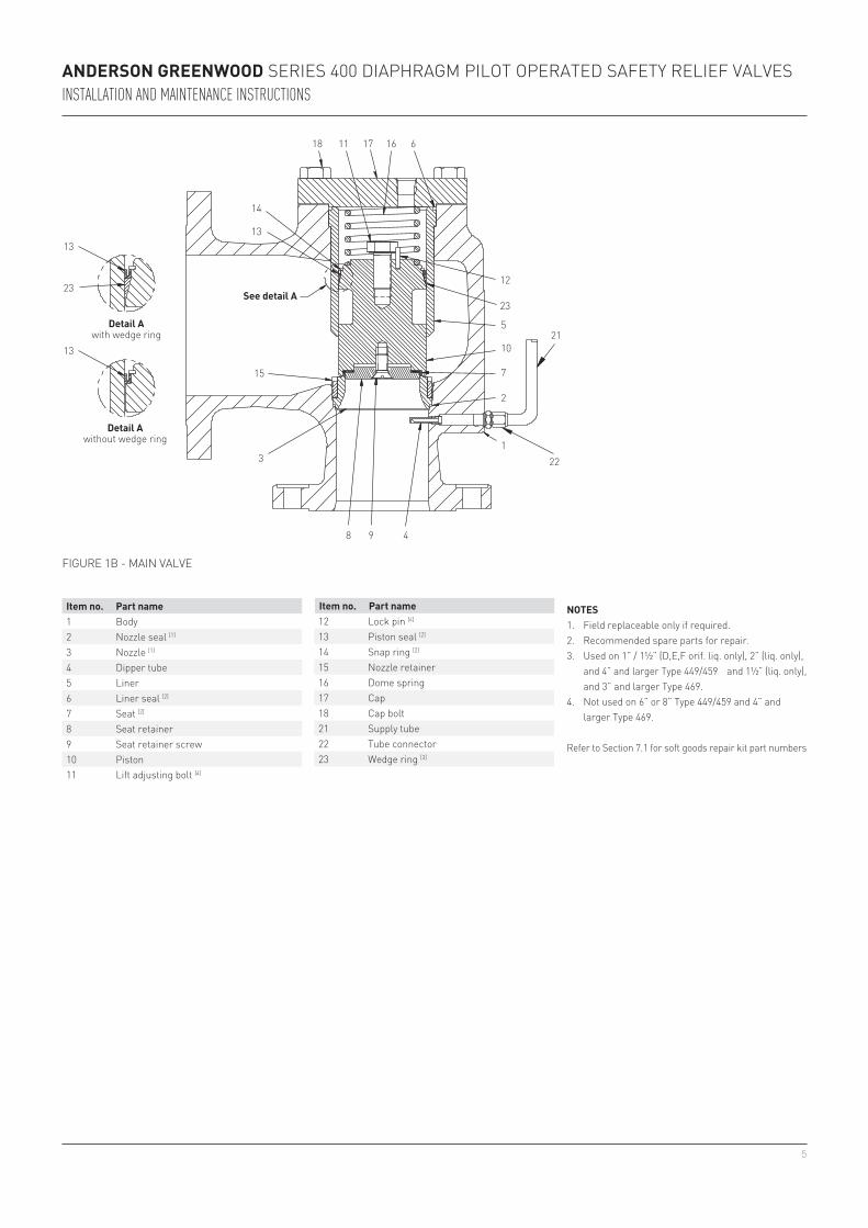
5
618 1711
12
8
13
14
15
3
9 4
16
23
5
10
7
2
122
21
13
13
23
Anderson Greenwood SerieS 400 Diaphragm pilot operateD Safety relief ValVeSInstallatIon and MaIntenance InstructIons
item no. part name1 Body2 Nozzle seal [1]
3 Nozzle [1]
4 Dipper tube5 liner6 liner seal [2]
7 Seat [2]
8 Seat retainer9 Seat retainer screw10 piston11 lift adjusting bolt [4]
notes1. field replaceable only if required.2. recommended spare parts for repair.3. Used on 1” / 1½” (D,e,f orif. liq. only), 2” (liq. only),
and 4” and larger type 449/459 and 1½” (liq. only), and 3” and larger type 469.
4. Not used on 6” or 8” type 449/459 and 4” and larger type 469.
refer to Section 7.1 for soft goods repair kit part numbers
figUre 1B - maiN ValVe
detail Awith wedge ring
see detail A
detail Awithout wedge ring
item no. part name12 lock pin [4]
13 piston seal [2]
14 Snap ring [2]
15 Nozzle retainer16 Dome spring17 Cap18 Cap bolt21 Supply tube22 tube connector23 Wedge ring [3]
6
Anderson Greenwood SerieS 400 Diaphragm pilot operateD Safety relief ValVeSInstallatIon and MaIntenance InstructIons
Body
Nozzle seal
Nozzle
Nozzle retainer
piston
liner
Spacer
Cap
Cap bolt
figUre 2
7
Anderson Greenwood SerieS 400 Diaphragm pilot operateD Safety relief ValVeSInstallatIon and MaIntenance InstructIons
3 pilot MAintenAnce
Refer to Figures 3, 4 and 5.arrange all parts in an orderly sequence on a flat work surface during disassembly. this will facilitate assembly and help ensure that the correct parts are assembled in the proper sequence.
3.1 disassemblyBefore beginning disassembly, bleed off any pressure trapped in the main valve or pilot.
3.1.1 Standard pilot - gas or liquid service
noteif the pilot is equipped with a lift lever, the lift lever handle assembly (item 50) must be removed from the cap (item 18) before continuing with disassembly. to do this, hold the lift lever handle in the position shown in figure 3, unscrew the handle assembly bushing (item 51) from the cap, and remove the handle assembly.
remove the cap (item 18), for pilot with lift lever remove jam nut (item 52) and lift lever nut (item 53), loosen the jam nut (item 17), and turn the adjustment screw (item 16) counterclockwise to relieve the spring tension. exercise caution when removing the spring bonnet (item 15) from pilots set above 500 psig, as spring tension is not completely relieved until the bonnet is removed. remove the spring bonnet, spring (item 6), and spring washers (item 13).
3.1.2 Iso-Dome pilot - gas service
noteall iso-Dome pilots are gas service pilots; however, fully assembled valves with these pilots may be either gas service valves or liquid services valves.
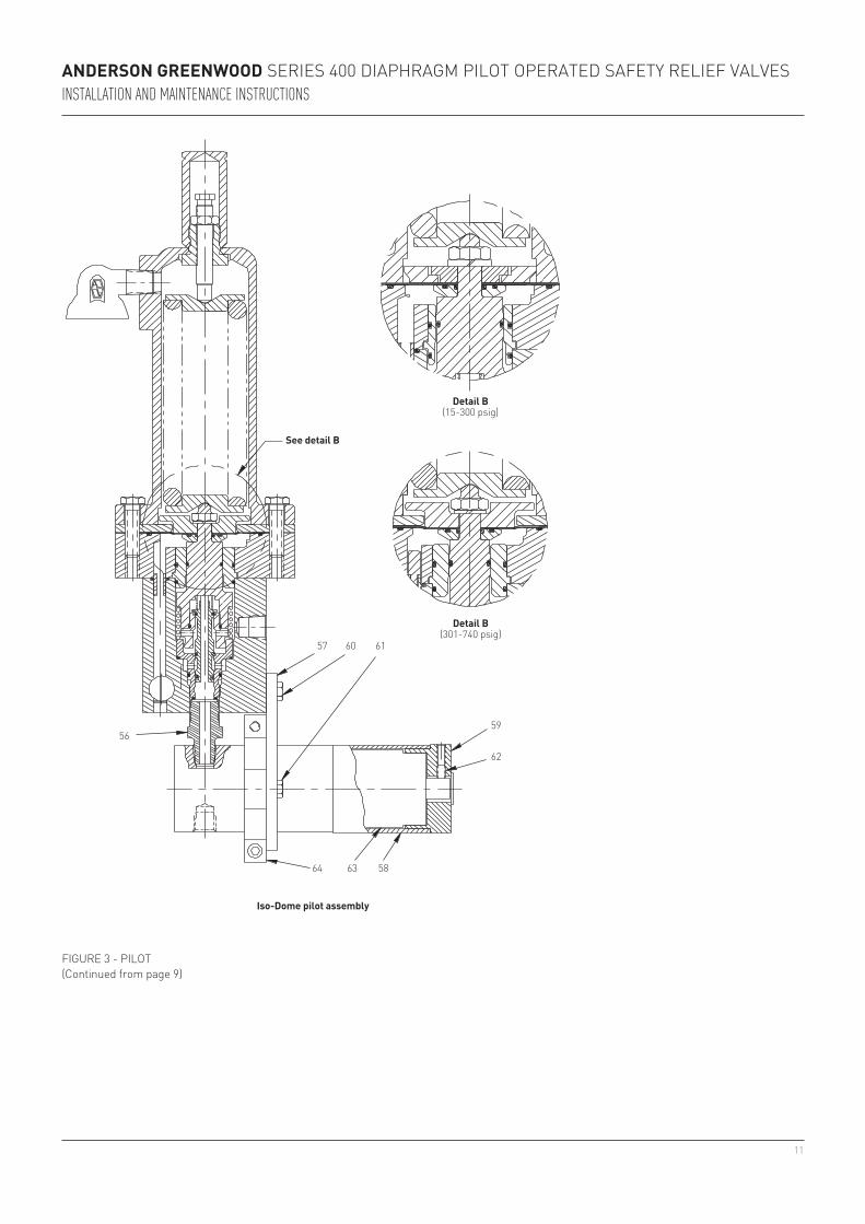
after bleeding off any pressure trapped in the main valve or pilot, remove the pilot with the regulator (item 63) attached from the main valve. Unscrew and remove bracket bolts (items 60) and bracket bolts (items 61). Slide the bracket (item 57) outward approximately 1½” along the regulator cover spacer (item 58).Using an 11/16” wrench, unscrew the adapter (item 56) with regulator attached from the body (item 1). if necessary, slide the bracket farther out along the cover spacer so that it does not hit the body. Support the regulator during this operation in order to avoid damaging the adapter threads or the body threads. loosen set screw (item 62) and remove regulator cover cap (item 59), regulator cover spaces (item 58), and bracket.Continue pilot disassembly in accordance with the procedures described in paragraph 3.1.1 except that the iso-Dome pilot uses an adapter in place of the body plug (item 2) in a standard pilot.
3.1.3 Iso-Sense pilot - gas or liquid servicethe iso-Sense pilot sectional drawing shown in figure 3 is presented for identification purposes only. this is a special pilot assembly which may incorporate non-standard components. Contact anderson greenwood for replacement parts and maintenance instructions for individual pilots (serial number is required for complete identification).
With the bonnet removed, the diaphragm case (item 14), diaphragm support plate (item 38) or sense plate (item 43), and sense washer (item 10) with internal parts attached can be removed from the body (item 1). Unscrew the piston nut (item 9) from the feedback piston (item 3) and remove the lockwasher (item 44). Disassemble the sense washer, diaphragm support plate or sense plate, diaphragm (item 4), diaphragm shield (item 47), diaphragm retaining washer (item 37), and piston sleeve (item 24) from the feedback piston. Unscrew the inlet nozzle (item 5) from the feedback piston. remove the spool spring (item 8) and inlet nozzle with the spool from the feedback piston.
remove the bias spring (item 11) and unscrew the body plug (item 2) from the body. Using a hex key (allen wrench) inserted through the bottom of the body into the hex socket in the outlet nozzle (item 28), unscrew the outlet nozzle and remove through the top of the body. Note that when viewed from the bottom of the body, the hex key is turned clockwise to unscrew the outlet nozzle.
8
Anderson Greenwood SerieS 400 Diaphragm pilot operateD Safety relief ValVeSInstallatIon and MaIntenance InstructIons
3.1.4 Pilot variations and accessoriesfor pilot equipped with a one-piece spool, figure 3 Style a, remove the spool seal (item 31) and the outlet seat (item 33) from the spool (item 34); then remove the spool from the inlet nozzle.
for pilot equipped with a three-piece spool, figure 3 Style e, unscrew the spool nut (item 48) from the inner spool (item 36), remove the outer spool (item 35) from the inlet nozzle and remove the inner spool from the outer spool.
for pilot equipped with a field test accessory, figure 4, remove this accessory with the shuttle from the body (item 1). Disassemble the dome connector from the field test body and remove the spring, plunger and shuttle.
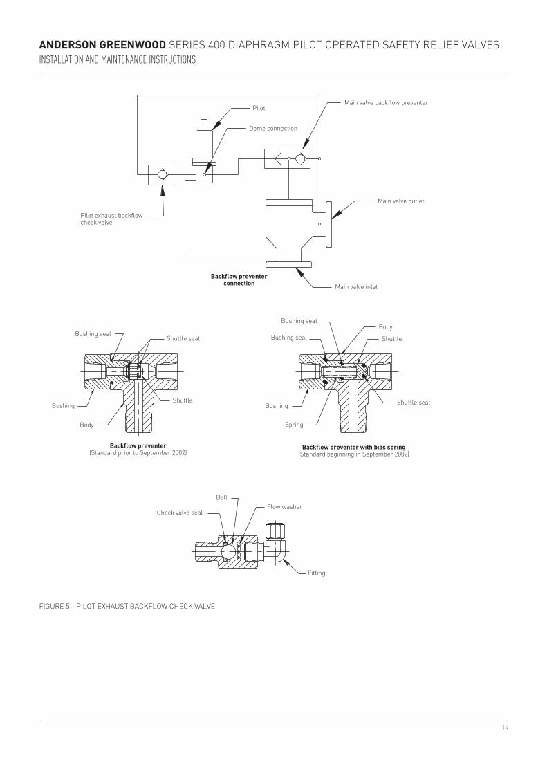
for pilot equipped with a backflow preventer and pilot exhaust backflow check valve, figure 5, remove these accessories from main valve dome port (backflow preventer) and the pilot exhaust port (backflow check valve). Unscrew the backflow preventer bushing from the body and remove the spring and shuttle. Unscrew the fitting from the backflow check valve body and remove the flow washer and ball.
remove and discard all old seats, seals and o-rings before beginning assembly.
3.2 Assembly3.2.1 Standard pilot - gas or liquid serviceassembly is done in the reverse order of disassembly. lightly lubricate all o-rings, all sliding surfaces, screw threads and spring washer pivot points with Dow Corning No. 33 silicone grease or equivalent. Do not lubricate the inlet seat (item 7) or the outlet seat (item 33). for pilot with lift lever, do not install lift lever handle assembly (item 50) until final pilot adjustment is completed, see paragraph 4.6. When assembling the pilot, the following should be observed:
3.2.2 Iso-Dome pilot - gas serviceall iso-Dome pilots are gas service pilots (see Note paragraph 3.1.2).
assemble pilot in accordance with procedures described in paragraph 3.2.1. Support the regulator when threading the adapter (item 56) with regulator attached into the body (item 1). With an 11/16” wrench used to back-up the adapter, the regulator may be rotated ± ¼ turn about the adapter axis to align the bracket (item 57) mounting surfaces on the body and the regulator bracket (item 64).
if alignment can not be achieved with ± ¼ turn, unthread the regulator from the adapter. Clean the ¼ Npt threads on the adapter and in the regulator outlet port and wrap the adapter threads with several wraps of ptfe thread seal tape. Screw the regulator onto the adapter and tighten sufficiently to effect a thread seal and alignment of the bracket mounting surfaces.
loosen the two #10-24 socket head cap screws in the regulator bracket so that the bracket can slide along the outside of the regulator. install the bracket (item 60) and hand tighten two bracket bolts into the body. hand tighten two bracket bolts into the regulator bracket and securely tighten the two #10-24 socket head cap screws into the regulator bracket. Securely tighten the four bracket bolts. Do not install the regulator cover spacer and regulator cover cap until final adjustment is completed, see paragraph 4.3.
diaphragm/piston assemblyassemble the diaphragm shield (item 47) on top of the diaphragm. assemble the diaphragm support plate (item 38), with the rounded edge towards the diaphragm shield. the nut holding the diaphragm/piston assembly together must not be torqued in excess of 10 ft. lbs. overtightening will damage the diaphragm.
pilot assembly and pretestWhen assembling diaphragm case sub-assembly to body sub-assembly, orient hole in case to fit over the length of damper bushing (item 23) projecting past the body face. engage spool in outlet nozzle and press gently until assembly drops into place.pretest to verify proper feedback piston function by depressing piston stack assembly
downward. the bias spring (item 11) should return the stack assembly to the upward position. if stack assembly does not return, identify and correct source of malfunction before completing assembly.
9
12
45
22
26
25
3
12 449
10
38
37
24
25
45
22
26
25
3
47, 4
14
46
23
7
27
20, 21
8
34
33
32
42
1 39 29 2 30 31
11
5
28
13
6
15
49
18
17
16
19
41
40
A
A
944
10
43
37
24
25
Anderson Greenwood SerieS 400 Diaphragm pilot operateD Safety relief ValVeSInstallatIon and MaIntenance InstructIons
3.2.3 Accessoriesassembly is done in the reverse order of disassembly. on backflow preventers (reference figures 4 and 5), lightly lubricate the bushing threads with Dow Corning No. 33 silicone grease or equivalent. a small amount of lubricant can be applied to the bushing seal(s).
Do not get any lubricant on the shuttle, shuttle seat(s) and or bushing seat. When re-installing the backflow preventer on the main valve dome port orient it so that the bushing is connected to the pilot (process) side.
Dome
detail A(15-300 psig)
detail A(301-740 psig)
inlet (½ Npt) outlet (¼ Npt)
Dome (¼ Npt)
section A - A
see detail A
style A(301-740 psig shown)
rotated 90° for clarity
figUre 3 - pilot(Continued thru page 12)
10
4835
36
53
52
51
50
55
54
Anderson Greenwood SerieS 400 Diaphragm pilot operateD Safety relief ValVeSInstallatIon and MaIntenance InstructIons
figUre 3 - pilot(Continued from page 9)
style e(301-740 psig shown)
lift lever assembly
11
56
57 60 61
59
62
64 63 58
Anderson Greenwood SerieS 400 Diaphragm pilot operateD Safety relief ValVeSInstallatIon and MaIntenance InstructIons
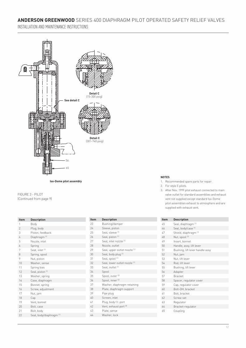
figUre 3 - pilot(Continued from page 9)
detail b(15-300 psig)
see detail b
detail b(301-740 psig)
iso-dome pilot assembly
12
56
65
Anderson Greenwood SerieS 400 Diaphragm pilot operateD Safety relief ValVeSInstallatIon and MaIntenance InstructIons
see detail c
detail c(15-300 psig)
detail c(301-740 psig)
figUre 3 - pilot(Continued from page 9)
item description1 Body2 plug, body3 piston, feedback4 Diaphragm [1]
5 Nozzle, inlet6 Spring7 Seat, inlet [1]
8 Spring, spool9 Nut, piston10 Washer, sense11 Spring bias12 Seal, piston [1]
13 Washer, spring14 Case, diaphragm15 Bonnet, spring16 Screw, adjustment17 Nut, jam18 Cap19 Vent, bonnet20 Bolt, case21 Bolt, body22 Seal, body/diaphragm [1]
notes1. recommended spare parts for repair.2. for style e pilots.3. after Nov. 1999 pilot exhaust connected to main
valve outlet for standard assemblies and exhaust vent not supplied except standard iso-Dome pilot assemblies exhaust to atmosphere and are supplied with exhaust vent.
iso-dome pilot assembly
item description23 Bushing/damper24 Sleeve, piston25 Seal, sleeve [1]
26 Seal, piston [1]
27 Seal, inlet nozzle [1]
28 Nozzle, outlet29 Seal, upper outlet nozzle [1]
30 Seal, body plug [1]
31 Seal, spool [1]
32 Seal, lower outlet nozzle [1]
33 Seat, outlet [1]
34 Spool35 Spool, outer [2]
36 Spool, inner [2]
37 Washer, diaphragm retaining38 plate, diaphragm support39 pipe plug40 Screen, inlet41 plug, body f.t. port42 Vent, exhaust port [3]
43 plate, sense44 Washer, lock
45 Seal, diaphragm [1]
46 Seal, body/case [1]
47 Shield, diaphragm [1]
48 Nut, spool [2]
49 insert, bonnet50 handle, assy, lift lever51 Bushing, lift lever handle assy52 Nut, jam53 Nut, lift lever54 rod, lift lever55 Bushing, lift lever56 adapter57 Bracket58 Spacer, regulator cover59 Cap, regulator cover60 Bolt-Dh, bracket61 Bolt, bracket62 Screw-set63 regulator64 Bracket-regulator65 Coupling
item description

13
A
A
Anderson Greenwood SerieS 400 Diaphragm pilot operateD Safety relief ValVeSInstallatIon and MaIntenance InstructIons
Dome connection port
Spring*
Shuttle seal
Shuttle*
plunger spring
Dome connector
plunger seal
field test body
plunger
plunger seat
* Spring based shuttle design standard from July 1st, 2002
view A - A
figUre 4 - fielD teSt aCCeSSory
14
Anderson Greenwood SerieS 400 Diaphragm pilot operateD Safety relief ValVeSInstallatIon and MaIntenance InstructIons
pilot exhaust backflow check valve
pilot
Dome connection
main valve backflow preventer
main valve outlet
main valve inlet
Body
Shuttle
Shuttle seat
Spring
Bushing
Bushing seal
Bushing seat
Bushing seal
BushingShuttle
Shuttle seat
Body
backflow preventer(Standard prior to September 2002)
backflow preventer with bias spring(Standard beginning in September 2002)
Ballflow washer
Check valve seal
fitting
backflow preventer connection
figUre 5 - pilot eXhaUSt BaCkfloW CheCk ValVe
15
Anderson Greenwood SerieS 400 Diaphragm pilot operateD Safety relief ValVeSInstallatIon and MaIntenance InstructIons
4 pilot AdjustMent
4.1 definitionsset pressure is defined as that pressure where the dome pressure is 70% of the supply pressure. this corresponds to the initial audible discharge of gas or first steady stream of liquid from the main valve.
crack pressure is defined as the supply pressure where gas or liquid flow begins at the pilot exhaust.
reseat pressure is defined as the supply pressure where the dome pressure increases to 75% of supply pressure. the dome pressure will continue to increase until the supply pressure decreases to 94% of set.
4.2 set pressure, standard pilot4.2.1 Gas service pilotto adjust the set pressure, a test setup similar to that shown in figure 6 should be used. the test media should be air. the adjustment screw should be turned iN most of the way. increase the supply pressure to nameplate setting and slowly back out the adjustment screw until flow through the pilot exhaust begins. Continue to slowly back out the adjustment screw until dome pressure is 70% of the supply pressure and the supply pressure meets the required set pressure tolerance of paragraph 4.5. after adjustment is completed, securely tighten the jam.
to determine reseat pressure, shut off the air supply and use the accumulator vent valve to slowly reduce the supply pressure until the dome pressure is 75% of supply pressure.
Close the shut-off valve and slowly open the bleed valve. When the dome pressure gauge reading is zero, the pilot may be removed from the test set-up.
4.2.2 Liquid service pilot
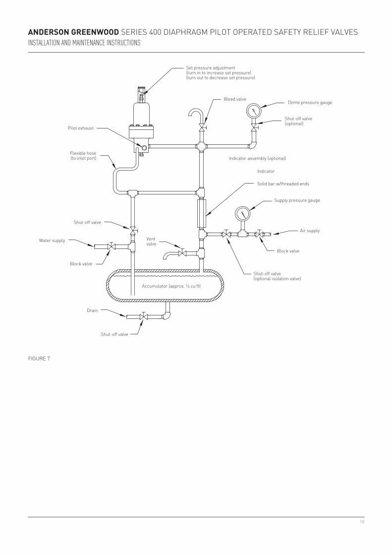
notean initial set pressure adjustment may be made with air as the supply pressure media using a test set-up similar to that shown in figure 6 and following the procedure described in paragraph 4.2.1 above. this initial set pressure will be approximately 1½% lower than the set pressure observed when the pilot is tested on liquid.
to adjust the set pressure, a test set-up similar to that shown in figure 7 should be used. the test media should be water. Some air volume must be maintained above the water surface in the accumulator.
Close the shut-off valve in the water line to the pilot inlet port and slowly open the bleed valve. When the dome pressure gauge reading is zero, the pilot may be removed from the test set-up.
the optional indicator assembly shown in figure 7 may be used for set pressure above 70 psig. if an indicator assembly is used, slowly increase the supply pressure until the indicator pin pulls into the indicator assembly and is approximately flush with the end of the indicator body. the pressure when the pin pulls in is the set pressure. loosen the jam nut, adjust the adjustment screw, and retighten the jam nut as required to meet the set pressure tolerance of paragraph 4.5.
Shut off the air supply and use the accumulator vent valve to slowly bleed down supply pressure until the indicator pin ‘pops’ out of the indicator assembly (full extension of the pin is approximately 7/16”). the pressure when the pin ‘pops’ out is the reseat pressure.
Close the shut-off valve in the water line to the pilot inlet port and slowly open the bleed valve. When the dome pressure gauge reading is zero, the pilot may be removed from the test set-up.
increase the air supply pressure to nameplate setting and slowly back out the adjustment screw until water flow through the pilot exhaust begins. Continue to slowly back out the adjustment screw until dome pressure is 70% of the supply pressure and the supply pressure meets the required set pressure tolerance of paragraph 4.5.
to determine reseat pressure, shut off the air supply and use the accumulator vent valve to slowly reduce supply pressure until the dome pressure is 75% of supply pressure.

16
Anderson Greenwood SerieS 400 Diaphragm pilot operateD Safety relief ValVeSInstallatIon and MaIntenance InstructIons
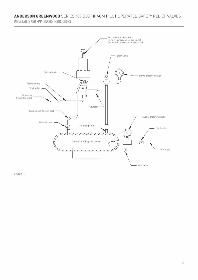
4.3 set pressure, iso-dome pilot
noteall iso-Dome pilots are gas service pilots (See Note paragraph 3.1.2).
4.3.1 Gas sense pilotto adjust set pressure, a test set-up similar to that shown in figure 8 should be used. the air supply to the regulator inlet should be adjusted so that the dome pressure gauge reading is 92% ± 2% of nameplate set pressure. the pressure at the regulator inlet should be a minimum of 200 psi greater than the specified dome pressure. the adjustment screw should be turned iN most of the way. generally it is not necessary to perform any service work on the regulator; however, if maintenance or repair is indicated, contact the regulator manufacturer for instructions and parts. the regulator output pressure should be adjusted if service was performed on the regulator or the pilot set pressure is being changed. apply pressure to the regulator inlet port of 200 psi greater than the specified dome pressure. Using a ½” open end wrench, turn the regulator adjusting screw, clockwise rotation increases and counterclockwise rotation decreases output pressure, as required to produce a dome pressure gauge reading equal to 92% ± 2% of the specified pilot set pressure. final adjustment should be made in the increasing pressure direction (with clockwise rotation). after final adjustment is completed, install the regulator cover spacer and the regulator cover cap. adjust regulator adjusting screw so that socket head set screw in regulator cover cap will tighten against the flat of the regulator adjusting screw. this may require ±¼ turn of regulator adjusting screw. Securely tighten the socket head set screw to lock the cover cap to the regulator adjusting screw.
wArninGIf regulator output pressure is set outside of the 92 ± 2% of nameplate set pressure limits, the pilot (and the assembled valve) set pressure may not comply with the tolerance requirements of Section VIII of the ASME Boiler and Pressure Vessel Code.
increase the supply pressure to the nameplate setting and slowly back out the adjustment screw until flow through the pilot exhaust begins. Continue to slowly back out the adjustment screw until dome pressure is 70% of the supply pressure. after adjustment is completed, securely tighten the jam nut.Close the block valve in the air supply line to the accumulator, close the block valve in the air supply line to the regulator, verify that the shut-off valve is open, slowly open the vent valve, and slowly open the bleed valve.
4.4 range of adjustmentall pilots can be adjusted ±5% beyond the nameplate setting. if a set pressure change is made that requires a new spring, consult factory or refer to appropriate spring chart in anderson greenwood report number 05.9065.017 to make proper selection.
4.3.2 Liquid sense pilotto adjust the set pressure, a test set-up similar to that shown in figure 9 should be used. the air supply to the regulator inlet should be adjusted so that the dome pressure gauge reading is 92% ± 2% of nameplate set pressure. the pressure at the regulator inlet should be a minimum of 200 psi greater than the specified dome pressure. generally it is not necessary to perform any service work on the regulator; however, if maintenance or repair is indicated, contact the regulator manufacturer for instructions and parts. if service was performed on the regulator or if the pilot set pressure is being changed, the regulator output pressure should be adjusted following the procedure described in paragraph 4.3.1.
adjust the pilot set pressure in accordance with procedure described in paragraph 4.2.2 except no initial set pressure adjustment is made.
Close the block valve in the air supply line to the accumulator, close the block valve in the air supply line to the regulator, verify that the shut-off valve in the water line to the pilot is open, slowly open the vent valve, and slowly open the bleed valve. When the supply pressure gauge and the dome gauge each read zero, the pilot may be removed from the test set-up.
When the supply pressure gauge and the dome pressure gauge each read zero, the pilot may be removed from the test set-up.

17
Anderson Greenwood SerieS 400 Diaphragm pilot operateD Safety relief ValVeSInstallatIon and MaIntenance InstructIons
cAutionTo avoid damaging any of the lift lever components, do not rotate the lift lever handle past that position where the cam surface of the handle assembly first contacts the lower face of the lift lever nut.
4.6 lift lever handle assembly installationfor pilot equipped with a lift lever, install the lift lever handle assembly (item 50) after completing the final pilot adjustment.Screw the lift lever nut (item 53) on the threaded portion of the lift lever rod (item 54) until the lower face of the lift lever nut is approximately 2 1/16” above the top of the spring bonnet (item 15). Use the jam nut to lightly lock the lift lever nut in place. Screw the cap on the threaded projection of the bonnet insert (item 52) until it is hand tight against the spring bonnet. the lower face of the lift lever nut should be even with the center of the threaded hole in the cap. if the lift lever nut is not positioned correctly, remove the cap and adjust the nuts as required, and reinstall the cap.
Set pressure adjustment (turn in to increase set pressure) (turn out to decrease set pressure)
Bleed valve
Dome pressure gauge
Supply pressure gauge
Block valvemounting stub
pilot exhaust*
flexible hose (to inlet port)
Shut-off valve
accumulator (approx. ¼ cu ft)
air supply
Vent valveVent fitting in pilot exhaust port not supplied with
standard pilots after Nov. 1999
figUre 6
4.5 perforMAnce requireMentsset pressure (psig) set pressure tolerance crack pressure minimum reseat pressure limits15-70 inclusive ± 2 psig 94% of set 0 to 3 psig below setabove 70 to 740 inclusive ± 3% 94% of set 96 to 100% of set
With the lift lever handle held in the position shown in figure 3, install the handle assembly by screwing the handle assembly bushing (item 51) into the cap. the cam surface of the lift lever handle assembly must contact the lower face of the lift lever nut between 15° and 45° of clockwise or counterclockwise rotation of the handle past its null or centered position. resistance of the handle indicates contact has occurred. if resistance occurs at less than 15°, the lift lever nut must be positioned higher. if resistance first occurs at more than 45°, the nut must be positioned lower on the lift lever rod.if necessary, remove the handle assembly from the cap following the procedure of paragraph 3.1 and repeat this assembly procedure in order to correctly position the lift lever nut and jam nut on the threaded portion of the lift lever rod. When correctly positioned lock the lift lever nut with the jam nut, install and securely tighten the cap, install the handle assembly, and securely tighten the handle assembly bushing.
18
Anderson Greenwood SerieS 400 Diaphragm pilot operateD Safety relief ValVeSInstallatIon and MaIntenance InstructIons
figUre 7
pilot exhaust
flexible hose (to inlet port)
Shut-off valve
Shut-off valve (optional isolation valve)
Shut-off valve (optional)
indicator assembly (optional)
indicator
Solid bar w/threaded ends
Supply pressure gauge
air supply
Water supply
Block valve
Drain
Block valve
Dome pressure gaugeBleed valve
Set pressure adjustment (turn in to increase set pressure) (turn out to decrease set pressure)
Vent valve
accumulator (approx. ¼ cu ft)
Shut-off valve
19
Anderson Greenwood SerieS 400 Diaphragm pilot operateD Safety relief ValVeSInstallatIon and MaIntenance InstructIons
figUre 8
Set pressure adjustment (turn in to increase set pressure) (turn out to decrease set pressure)
Dome pressure gauge
Shut-off valve
flexible hose (to inlet port)
pilot exhaust
Block valve
flexible hose
accumulator (approx. ¼ cu ft)
Bleed valve
air supply
Block valve
Supply pressure gauge
Vent valve
regulator
mounting stub
air supply (regulator inlet)

20
Anderson Greenwood SerieS 400 Diaphragm pilot operateD Safety relief ValVeSInstallatIon and MaIntenance InstructIons
figUre 9
Set pressure adjustment (turn in to increase set pressure) (turn out to decrease set pressure)
Dome pressure gauge
Shut-off valve
flexible hose (to inlet port)
pilot exhaust
Block valveflexible hose
accumulator (approx. ¼ cu ft)
Bleed valve
air supply
Block valve
Supply pressure gauge
Vent valve
regulator
air supply (regulator inlet)
Block valve
Shut-off valve
Shut-off valve (optional isolation valve)
Shut-off valve (optional)
Solid bar w/threaded ends
Water supply
Drain

21
Anderson Greenwood SerieS 400 Diaphragm pilot operateD Safety relief ValVeSInstallatIon and MaIntenance InstructIons
5 vAlve AsseMbly testinG
5.1 Generalthe complete valve assembly should be tested for internal and external leakage and to verify set pressure using a test set-up similar to that shown in figure 10, 11, or 12. the test media should be air.
cAutionDo not test liquid service valves using water or other liquid test media. Liquid service valves should be tested using air as the test media in accordance with the procedures described below. Testing fully assembled liquid service valves using air ensures that no water or other liquid will remain in the main valve dome after final valve testing.
5.2 low pressure leakage check
notefor valve with iso-Dome pilot, apply regulator supply pressure equal to a minimum of 200 psi greater than 92% of set pressure.
5.2.1 Valve for gas service or valve with Iso-Dome pilotSlowly increase the supply pressure to 30% of set pressure. Check for main valve nozzle, seat, and piston seal leakage at the main valve outlet. to help in seating the valve seat and piston seal, the valve may be actuated several times. No leakage shall occur in 15 seconds.
5.2.2 Valve for liquid serviceSlowly increase supply pressure to 30% of set pressure. Check for main valve nozzle, seat, and piston seal leakage at the main valve outlet. to help in seating the valve seat and piston seal, the valve may be actuated several times. No leakage shall occur in 15 seconds. if leakage is detected at the valve outlet, note the leakage in bubbles observed in 15 seconds and remove the leakage test device from the outlet flange. With the same supply pressure applied to the valve inlet, use a bubble test leak detector to measure leakage through the pilot exhaust. low pressure leakage performance is acceptable if the leakage at the main valve outlet is equal to the pilot exhaust leakage and this leakage value does not exceed 15 bubbles in 15 seconds.
liquid service valve with iso-Dome pilot should be tested per paragraph 5.2.1.
5.3 High pressure leakage check
notefor valve with iso-Dome pilot, apply regulator supply pressure equal to a minimum of 200 psi greater than 92% of set pressure.
5.3.1 Valve for gas service or valve with Iso-Dome pilotapply supply pressure to the inlet equal to 90% of the set pressure. Check for leakage at the main valve outlet. Using a suitable gas and air leak detector solution, check for leakage at the cap seal and other pressure connections. No leakage shall occur at the valve outlet and no visible leakage shall be detected at the cap seal or other pressure connections in one minute.
5.3.2 Valve for liquid serviceapply supply pressure to the inlet equal to 90% of the set pressure. Check for leakage at the main valve outlet. Using a suitable gas and air leak detector solution, check for leakage at the cap seal and other pressure connections. No leakage shall occur at the valve outlet and no visible leakage shall be detected at the cap seal or other pressure connections in one minute. if leakage is detected at the valve outlet, note the leakage in bubbles observed in one minute and remove the leakage test device from the outlet flange. With the same supply pressure applied to the valve inlet use a bubble test leak detector to measure leakage through the pilot exhaust. high pressure leakage performance is acceptable if the leakage at the main valve outlet is equal to the pilot exhaust leakage and this leakage value does not exceed 60 bubbles in one minute.
liquid service valve with iso-Dome pilot to be tested per paragraph 5.3.1.
Where superimposed back pressure is specified, the downstream or exhaust connections which are exposed to the back pressure shall be tested at 1.5 times the specified back pressure and all mechanical connections so pressurized will be checked for leaks. No visible leakage shall occur in one minute using a suitable gas and air leak detector solution.
22
.10
.10
Anderson Greenwood SerieS 400 Diaphragm pilot operateD Safety relief ValVeSInstallatIon and MaIntenance InstructIons
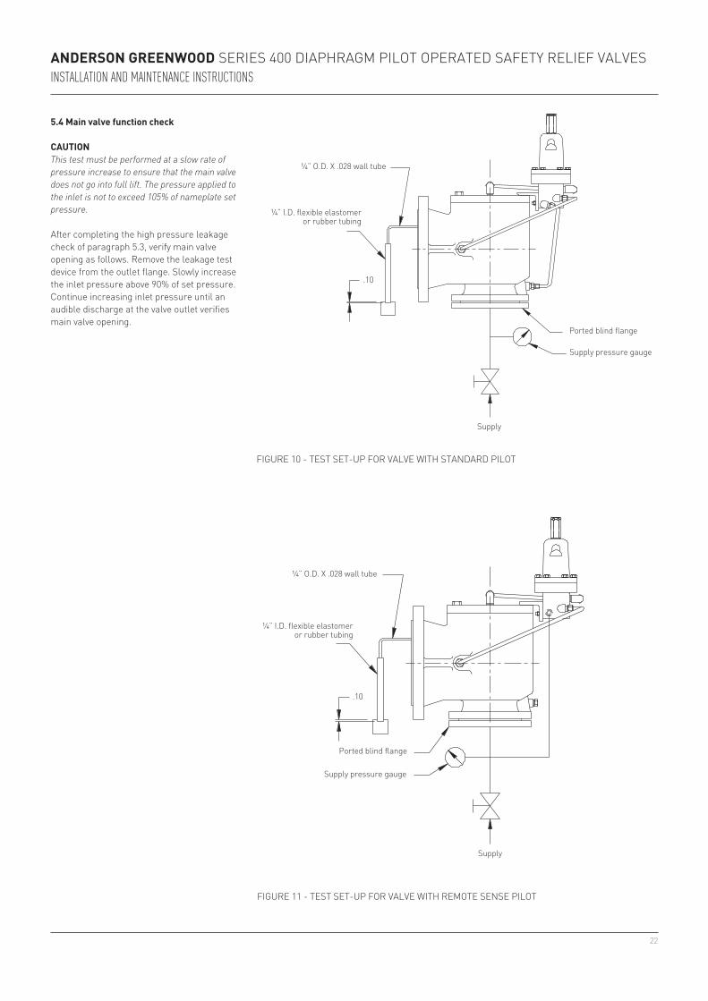
5.4 Main valve function check
cAutionThis test must be performed at a slow rate of pressure increase to ensure that the main valve does not go into full lift. The pressure applied to the inlet is not to exceed 105% of nameplate set pressure.
after completing the high pressure leakage check of paragraph 5.3, verify main valve opening as follows. remove the leakage test device from the outlet flange. Slowly increase the inlet pressure above 90% of set pressure. Continue increasing inlet pressure until an audible discharge at the valve outlet verifies main valve opening.
ported blind flange
Supply pressure gauge
Supply
¼” o.D. X .028 wall tube
¼” i.D. flexible elastomer or rubber tubing
figUre 10 - teSt Set-Up for ValVe With StaNDarD pilot
figUre 11 - teSt Set-Up for ValVe With remote SeNSe pilot
¼” o.D. X .028 wall tube
¼” i.D. flexible elastomer or rubber tubing
ported blind flange
Supply pressure gauge
Supply

23
.10
Anderson Greenwood SerieS 400 Diaphragm pilot operateD Safety relief ValVeSInstallatIon and MaIntenance InstructIons
figUre 12 - teSt Set-Up for ValVe With iSo-Dome pilot
¼” o.D. X .028 wall tube
¼” i.D. flexible elastomer or rubber tubing
ported blind flange
Supply pressure gauge
Supply
regulator supply
regulator supply pressure gauge
iso-Dome pilot
5.7 iso-sense pilot operated pressure relief valvein this special pilot operated pressure relief valve, the sense pressure applied to the pilot inlet/sense port is supplied from a remote source and the sense pressure media is isolated from the process media. the valve assembly is available for either a gas or liquid process media with either a gas or liquid sense media. the typical iso-Sense pilot operated pressure relief valve shown in figure 13 below is presented for identification purposes only. this is a special pressure relief valve assembly which may require special set pressure adjustment procedures. Contact anderson greenwood for replacement parts and maintenance instructions for individual valve assemblies (serial number is required for complete identification).
remote isolated sense pressure line
iso-Sense pilot
figUre 13 - iSo-SeNSe pilot operateD preSSUre relief ValVe
24
Anderson Greenwood SerieS 400 Diaphragm pilot operateD Safety relief ValVeSInstallatIon and MaIntenance InstructIons
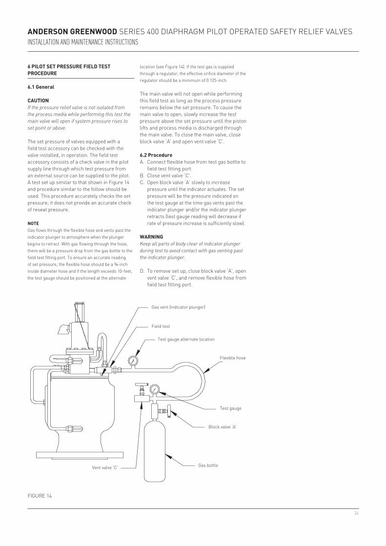
figUre 14
6 pilot set pressure field test procedure
6.1 General
cAutionIf the pressure relief valve is not isolated from the process media while performing this test the main valve will open if system pressure rises to set point or above.
the set pressure of valves equipped with a field test accessory can be checked with the valve installed, in operation. the field test accessory consists of a check valve in the pilot supply line through which test pressure from an external source can be supplied to the pilot. a test set up similar to that shown in figure 14 and procedure similar to the follow should be used. this procedure accurately checks the set pressure; it does not provide an accurate check of reseat pressure.
notegas flows through the flexible hose and vents past the indicator plunger to atmosphere when the plunger begins to retract. With gas flowing through the hose, there will be a pressure drop from the gas bottle to the field test fitting port. to ensure an accurate reading of set pressure, the flexible hose should be a ⅜-inch inside diameter hose and if the length exceeds 10-feet, the test gauge should be positioned at the alternate
field test
gas vent (indicator plunger)
test gauge alternate location
flexible hose
test gauge
Block valve ‘a’
Vent valve ‘C’ gas bottle
6.2 procedurea. Connect flexible hose from test gas bottle to
field test fitting port.B. Close vent valve ‘C’.C. open block valve ‘a’ slowly to increase
pressure until the indicator actuates. the set pressure will be the pressure indicated on the test gauge at the time gas vents past the indicator plunger and/or the indicator plunger retracts (test gauge reading will decrease if rate of pressure increase is sufficiently slow).
wArninGKeep all parts of body clear of indicator plunger during test to avoid contact with gas venting past the indicator plunger.
D. to remove set up, close block valve ‘a’, open vent valve ‘C’, and remove flexible hose from field test fitting port.
location (see figure 14). if the test gas is supplied through a regulator, the effective orifice diameter of the regulator should be a minimum of 0.125-inch.
the main valve will not open while performing this field test as long as the process pressure remains below the set pressure. to cause the main valve to open, slowly increase the test pressure above the set pressure until the piston lifts and process media is discharged through the main valve. to close the main valve, close block valve ‘a’ and open vent valve ‘C’.
25
Anderson Greenwood SerieS 400 Diaphragm pilot operateD Safety relief ValVeSInstallatIon and MaIntenance InstructIons
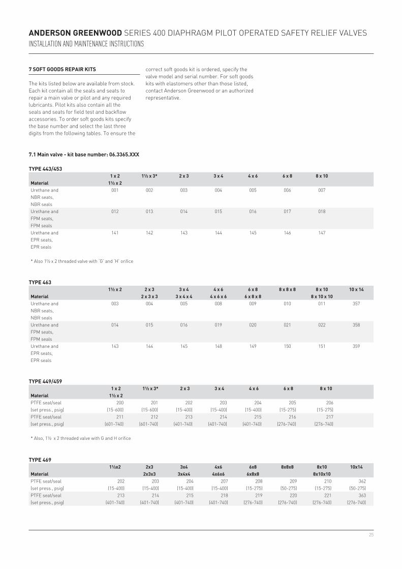
7 soft Goods repAir kits
the kits listed below are available from stock. each kit contain all the seals and seats to repair a main valve or pilot and any required lubricants. pilot kits also contain all the seals and seats for field test and backflow accessories. to order soft goods kits specify the base number and select the last three digits from the following tables. to ensure the
7.1 Main valve - kit base number: 06.3365.XXX
type 443/453
Material1 x 2 1½ x 3* 2 x 3 3 x 4 4 x 6 6 x 8 8 x 10
1½ x 2Urethane and 001 002 003 004 005 006 007NBr seats,NBr sealsUrethane and 012 013 014 015 016 017 018fpm seats,fpm sealsUrethane and 141 142 143 144 145 146 147epr seats,epr seals
* also 1½ x 2 threaded valve with ‘g’ and ‘h’ orifice
type 463
Material1½ x 2 2 x 3 3 x 4 4 x 6 6 x 8 8 x 8 x 8 8 x 10 10 x 14
2 x 3 x 3 3 x 4 x 4 4 x 6 x 6 6 x 8 x 8 8 x 10 x 10Urethane and 003 004 005 008 009 010 011 357NBr seats,NBr sealsUrethane and 014 015 016 019 020 021 022 358fpm seats,fpm sealsUrethane and 143 144 145 148 149 150 151 359epr seats,epr seals
type 449/459
Material1 x 2 1½ x 3* 2 x 3 3 x 4 4 x 6 6 x 8 8 x 10
1½ x 2ptfe seat/seal 200 201 202 203 204 205 206(set press., psig) (15-600) (15-600) (15-400) (15-400) (15-400) (15-275) (15-275)ptfe seat/seal 211 212 213 214 215 216 217(set press., psig) (601-740) (601-740) (401-740) (401-740) (401-740) (276-740) (276-740)
* also, 1½ x 2 threaded valve with g and h orifice
type 469
Material1½x2 2x3 3x4 4x6 6x8 8x8x8 8x10 10x14
2x3x3 3x4x4 4x6x6 6x8x8 8x10x10ptfe seat/seal 202 203 204 207 208 209 210 362(set press., psig) (15-400) (15-400) (15-400) (15-400) (15-275) (50-275) (15-275) (50-275)ptfe seat/seal 213 214 215 218 219 220 221 363(set press., psig) (401-740) (401-740) (401-740) (401-740) (276-740) (276-740) (276-740) (276-740)
correct soft goods kit is ordered, specify the valve model and serial number. for soft goods kits with elastomers other than those listed, contact anderson greenwood or an authorized representative.
26
Anderson Greenwood SerieS 400 Diaphragm pilot operateD Safety relief ValVeSInstallatIon and MaIntenance InstructIons
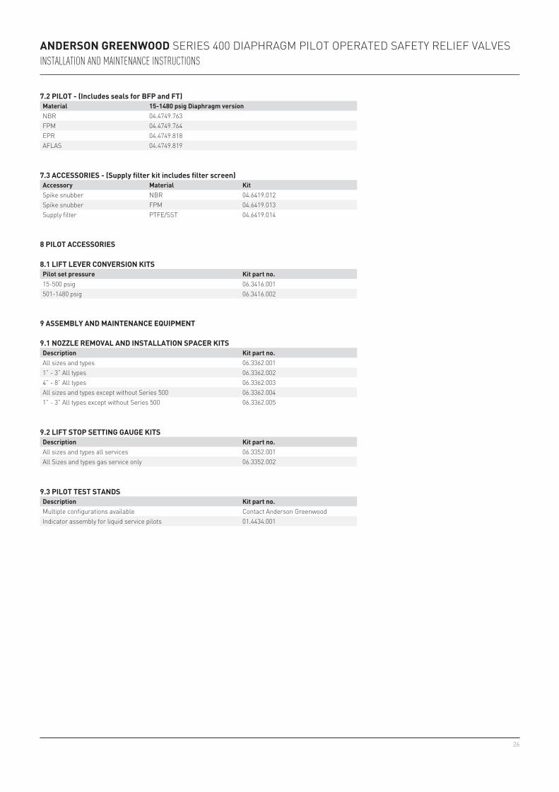
7.2 pilot - (includes seals for bfp and ft)Material 15-1480 psig diaphragm versionNBr 04.4749.763fpm 04.4749.764epr 04.4749.818aflaS 04.4749.819
8.1 lift lever conversion kitspilot set pressure kit part no.15-500 psig 06.3416.001501-1480 psig 06.3416.002
9.1 nozzle reMovAl And instAllAtion spAcer kitsdescription kit part no.all sizes and types 06.3362.0011” - 3” all types 06.3362.0024” - 8” all types 06.3362.003all sizes and types except without Series 500 06.3362.0041” - 3” all types except without Series 500 06.3362.005
7.3 Accessories - (supply filter kit includes filter screen)Accessory Material kitSpike snubber NBr 04.6419.012Spike snubber fpm 04.6419.013Supply filter ptfe/SSt 04.6419.014
9.2 lift stop settinG GAuGe kitsdescription kit part no.all sizes and types all services 06.3352.001all Sizes and types gas service only 06.3352.002
9.3 pilot test stAndsdescription kit part no.multiple configurations available Contact anderson greenwoodindicator assembly for liquid service pilots 01.4434.001
8 pilot Accessories
9 AsseMbly And MAintenAnce equipMent