manual - lmg100 econolev (english - pdf - manual) · see data sheets for specific requirements. ......
TRANSCRIPT

LMG100 EconolevMagnetic level gaugeKTEK products
Operation instruction manual OI/LMG100-EN
IntroductionABB offers the standard LMG100 Econolev Magnetic Level Gauge with a 316 stainless steel chamber, a custom engineered float and all accessories with 316 stainless steel construction.
Measurement made easy

2 LMG100 Magnetic Level Gauge | Operating instruction manual
TABLE OF CONTENTS1. INTRODUCTION .............................................................................................................................................. 3 1.1 General Description ...................................................................................................................... 3 2. STORAGE & HANDLING INFORMATION ........................................................................................................ 3
3. INSTALLATION ................................................................................................................................................ 3 3.1 Float Information ........................................................................................................................... 3 3.2 Leveling ......................................................................................................................................... 3 3.3 Limit Switches ............................................................................................................................... 4 3.3.1 Limit Switch Use............................................................................................................ 6 3.4 Magnetostrictive Transmitter Installation ....................................................................................... 7 3.5 Isolation Valves ............................................................................................................................. 7 3.6 Replacing Indicator Tube .............................................................................................................. 7
4. TROUBLESHOOTING ...................................................................................................................................... 8 4.1 Indicator Decoupling ..................................................................................................................... 8 4.2 Float Sinks or Sticks ..................................................................................................................... 8 4.3 Switch Does Not Work .................................................................................................................. 8
5. PARTS ORDERING ......................................................................................................................................... 9
6. CUSTOMER SPECIFIC PRODUCT INFORMATION ....................................................................................... 9
7. APPENDIX A .............................................................................................................................................. 10 7.1 LMG100 Parts Breakdown Drawing ............................................................................................ 10
8. APPENDIX B ...............................................................................................................................................11 8.1 Unpacking ....................................................................................................................................11 8.2 Pre-Installation Checklist .............................................................................................................11 8.3 Equipment & Tools .......................................................................................................................11 8.4 Placing an MLG in Service (Startup) ............................................................................................11 8.5 Maintenance ............................................................................................................................... 12 8.6ReplacementGlassInstallationProcedure(RetrofitorReplacement) ....................................... 12 8.6.1 LMG100 Shuttle Replacement Glass Installation Procedure (refer to Figures 8-1 and 8-2) 12 8.7 LMG100 Shuttle Replacement Glass Installation Procedure ...................................................... 13
9. APPENDIX C .............................................................................................................................................. 15 9.1 Warranty Statement .................................................................................................................... 15 9.2 RMA Form ................................................................................................................................... 16

Operating instruction manual | LMG100 Magnetic Level Gauge 3
1.0 Introduction 1.1 General Description Features: • Rugged construction • Safeforflammable,corrosive,andtoxicliquids • Suitableforpressuresfromfullvacuumtomaximumspecifiedpressure • Special types for high and low temperature operations • Positive zero indication • Available with integral limit switches & transmitters
ThebasicLMG100systemsconsistofafloat,floatchamberandanindicatorassembly.Thefloatchamberiscon-necteddirectlytotheprocessvessel.Thefloatchambercontainsamagnetassemblyandisdesignedandweightedtofloatintheprocessliquidsubmergedapproximately70to80%.Theindicatorassemblyconsistsofasealedpoly-carbonate tube containing the shuttle indicator and a graduated scale corresponding to the desired operating range. Theindicatorassemblyismountedincloseproximitytothefloatchamber.Magneticcouplingexistsbetweenthefloatandtheindicator.Asthefloatfollowschangingliquidlevel,theindicatorchangespositiontoreflectthatlevelduetothe coupling action.
2.0 Storage and Handling InformationTopreventdamagetotheshippingtubesand/orcratesthatthelevelgaugesaretransportedin,theseitemsshouldnotbeover-exposedtoinclementweather.TheLMG100MagneticLevelGaugeshouldbestoredinsuchamannerthatwouldnotallowtheindicatortubetobeimmersedorsubmergedinanyliquid.Sufficientprecautionsshouldbetakenso that the polycarbonate indicator tubes are not broken or damaged. There are no special storage requirements for theECchamberthemselves,butifthereisatransmitterand/orswitch,thestoragerequirementsofthetransmitterand/orswitchmustbemet.Seedatasheetsforspecificrequirements.
3.0 Installation3.1 Float InformationTheLMG100floatisshippedinsidethechamberunlessspecifiedforseparateshipment.Mostfloatsarelabeledtoindicatethetopofthefloat,thespecificgravityofthefluid,andtheserialnumberofthechamberforwhichtheyaredesigned.Thetopofthefloatcanbefoundbylocatingthemagnetplacementanddirectionwithrespecttotheindicatorinthescale.Theindicatorshouldbeattractedtothefloat,notrepelled,wheninsertedcorrectly. Floatsandindicatorsaredesignedsothatthemagneticactuationpointofthemagnetscoincidewiththefluidlevelatthereferencespecificgravity.Ifspecificgravitydecreases,thefloatwillhavemoreofitslengthbelowthefluidlevelandgiveavisualindicationthatislowerthanactuallyexists.Ifthefluidspecificgravityhassignificantlychangedafterthe unit has been placed in service.
3.2 LevelingThechambermustbeverticallyleveltoinsureproperoperationofthefloatanditsfollower.Aunitthatisnotleveledproperlymaydecoupleunexpectedlyduetofrictionwiththesidesorbecausethefloattravelstoofarawayfromtheindicator.
3.3 Limit SwitchesTosignalspecificliquidlevels,theLMG100canbeequippedwithdifferenttypesofABBlimitswitches.Magneticallyactuated limit switches are the most commonly used devices. They can be clamped to the measuring chamber and are adjustableovertheentiremeasuringrange.Theyareactuatedbyamagnetincorporatedintothefloat.Theprocessoperatingconditionswilldefinewhatlimitswitchtypemaybeused(Table3-1).
Available magnetically actuated switches (Table 3-1):Reed Type: MS30 & MS30EXCamActionType:MS40,MS40EX,&MS41Pneumatic Type: PS35 & PS45

4 LMG100 Magnetic Level Gauge | Operating instruction manual
3.3 Limit Switches (continued)All limit switches are delivered as factory assembled to the LMG100 in most cases (Figure 3-1). Please consult the applicablelimitswitchproductdatasheetsforspecifications,dimensions,ratings,andapprovals.
Figure 3-1
3.3.1 Limit Switch Use A magnetically actuated limit switch is usually mounted using twostainlesssteelclampsthatarefastened,thenattachedto the switch housing and strapped around the LMG100 chamber. The switch can be easily positioned by loosening the clamp with a 5/16” nut driver and sliding the switch to the correct position on the chamber (Figure 3-2).
Figure 3-2

Operating instruction manual | LMG100 Magnetic Level Gauge 5
Mod
el #
Agen
cy A
ppro
vals
Encl
osur
eSw
itchi
ng M
echa
nism
Appl
icat
ion
Type
Rat
ing
Elec
trica
l C
onne
c-tio
n
Type
Rat
ing
Min
Pro
cess
Te
mp
Dea
d-ba
ndC
onta
cts
Hig
h Te
mp
Vibr
a-tio
nH
igh
Cor
ro-
sion
MaxProcess
Tem
p
MS3
0FM
,CSA
Her
met
ical
ly
Seal
edNEM
A4x
1/2”
MN
PTR
eed
AC/D
C
1 am
p-4
0°F
(-40°
C)
1/8”
SPD
T•
300°
F (1
49°C
); 60
0°F
(316
°C)
MS3
0/EX
FM,C
SAH
erm
etic
ally
Se
aled,E
x-pl
osio
n Pr
oof
NEM
A4x
1/2”
FN
PTR
eed
AC/D
C
1am
p-4
0°F
(-40°
C)
1/8”
SPD
T•
300°
F (1
49°C
); 60
0°F
(316
°C)
MS4
0FM
,CSA
Stai
nles
s St
eel
NEM
A4x
1/2”
FN
PTCam
Driven,
Snap
Act
ion
AC: 1
0 am
pD
C: 2
.6
amp
-60°
F (-5
1°C
)7/
8”D
PDT
••
•30
0°F
(149
°C);
600°
F (3
16°C
)
MS4
0/EX
FM,C
SASt
ainl
ess
Steel,Explo-
sion
Pro
of
NEM
A4x
3/4”
FN
PTCam
Driven,
Snap
Act
ion
AC:
10am
pD
C:1
/2
amp
-60°
F (-5
1°C
)13
/16”
DPD
T•
••
300°
F (1
49°C
); 60
0°F
(316
°C)
MS4
1FM
,CSA
,ATE
XSt
ainl
ess
Steel,Dual
Com
partm
ent,
Her
met
ical
ly
Sealed,E
x-pl
osio
n Pr
oof
NEM
A4x
1/2”
FNPT
Cam
Driven,
Snap
Act
ion
AC:
10am
pD
C: 2
.6
amp
-320
°F (-
195°
C)
with
opt
ion
15/1
6”D
PDT
••
•30
0°F
(149
°C);
1000
°F (5
38°C
)
PS35
Non
-ele
ctric
Stai
nles
s St
eel
NEM
A4x
1/8”
MN
PT
port
Pneu
mat
ic15
to
100
psig
0°F
(-18°
C)
1”Pn
eu-
mat
ic
Sign
al•
180°
F (8
2°C
); 45
0°F
(232
°C)
PS45
Non
-ele
ctric
Stai
nles
s St
eel
NEM
A4x
1/8”
MN
PT
port
Pneu
mat
ic1
to 1
00
psig
0°F
(-18°
C)
15/1
6”Pn
eu-
mat
ic
Sign
al•
180°
F (8
2°C
); 45
0°F
(232
°C)
*Requiresuseofinsulationpadorinsulationjacket/rodmountassem
bly.C
onsultspecificproductdatasheetfordetailedguidance.
Table 3-1

6 LMG100 Magnetic Level Gauge | Operating instruction manual
3.4 Magnetostrictive Transmitter Installation
Use the followingsteps tosuccessfully installaMagnetostrictiveLevelTransmitter (MLT)onanexistingMagneticLevel Gauge (MLG). Read all directions carefully before performing any operation. The common mounting location of the transmitter will be on the left hand side of the gauge (when facing the scale) at 90º from the scale.
1. The model number will appear as AT600/B/... to identify electronics housing mounted on the bottom of the probe.2. Compare the measuring length of the transmitter (the last numbers in the model number) with the measuring
length of the MLG and the center to center dimension if the MLG to determine if the transmitter should match the scale measurement or the center to center of the process connections.
3. Identify the “Factory Zero Mark” sticker on the sensor tube of the transmitter.4. Block the MLG from the process.5. DraintheMLGfollowingplantproceduresforpressurereliefanddisposalofprocessfluids.
B. Ifthetransmittermeasuringlengthmatchesthecentertocenterofthegauge,alignthezeromarkwiththecenter of the bottom process connection.
6. Slightly loosen all but the uppermost worm gear clamps which attach the scale assembly to the MLG.7. Realign the zero mark of the transmitter with the corresponding zero on the MLG.8. Startingwith the highest transmittermounting clamp, loosen each transmitter clamp, slide the clamp over or
throughthemountingtabofthetransmitter,andtightentheclamp.9. Repeat step 12 until all transmitter mounting clamps are tightened.10. Tighten all scale mounting clamps being sure to align the scale vertically on the MLG.11. Toconfirmthezeroofthetransmitter,applypowertotheterminalstripofthemagnetostrictivetransmitter.Ifthe
transmitterreadshigherthan“zero”,raisethetransmitter. If thetransmitterreads lowerthan“zero”, lowerthetransmitter.
12.Attachproperfieldwiringtothetransmitteraccordingtotheinstructionmanual,includedwiththetransmitter.13. Open the process to the MLG using the procedure included in Section 3.6.
3.5 Isolation Valves
Valves should be installed between the tank and the KM26 for maintenance purposes and are available as an option.
Caremustbeusedwhenopeningthevalvestopreventasurgeoffluidorgasesthroughthechamber.Asurgecancausethefloattobepropelledagainstthefarstopcausingdamagetothefloatshelland/ortheindicatorglass.Failuretocomplymayresultindamagetothefloatandexpensetothecustomer.Graduallyopentheupperisolationvalveprior to the lower one to equalize the pressure in the level gauge chamber with the pressure in the vessel. After the
pressurehasequalized,graduallyopenthelowerisolationvalve.Atthispoint,thelevel indicator may show a liquid level if enough liquid is present.
3.6 Replacing Indicator Tube1. Remove the machine screw in the upper tube holder. Remove the upper tube
holder by sliding it out of the end of the channel (do not pull forward). For units 60” or longer remove all of the stain-less steel wires that retain the tube in the channel. Slide the tube to be replaced out of the end of the channel.
2. Beforeinstallingreplacementtube,checkforproperorientation.Thebottomoftheshuttletubewillhaveanor-ange “PAC-MAN” shaped silicon bumper inside the tube. The bottom of the magnetic bar graph glass tube will have an indentation to align with the bottom tube holder. Insert the replacement tube into the bottom holder. Install the top holder using the machine screw to hold in place. Replace any stainless steel wires necessary to retain the tube in the channel.

Operating instruction manual | LMG100 Magnetic Level Gauge 7
4.0 Troubleshooting
4.1 Indicator DecouplingCauses:• Floatisupsidedown.Remove,checkfieldstrengthofmagnets,andinstallcorrectly.Proximitytoopposingfield
mayweakenmagneticfield.• Scaleassemblyisnotflatagainstthechamberduetomissingstraps.Magneticfieldstrengthdropsexponentially
with distance. Add gear clamps to eliminate channel separation from chamber. Add stainless steel retaining wires to eliminate indicator tube separation from channel.
• Floatstopspringshavebeenbentorbroken.Adjustorreplacespringsasneededtopreventfloattraveloutsidethe range of the indicator tube.
• Scalehasbeenmovedallowingfloattraveloutsideofrangeorcausingtoomuchseparationfromthefloat.Reposi-tion the scale.
• Floatorindicatorde-magnetizingbyproximitytoothermagneticmaterial,hightemperature,orrepulsivefields.Consultfactoryforre-magnetizationoffloatorreplacethefloatand/orindicatorandremovethesourceofdemag-netization.Sourcesincludefloatsandswitchesinstalledupsidedown,closeferrousmaterials,nearbymagneticfields,magneticparticlesfromprocesspiping,etc.
• Indicator tube is no longer sealed and contains moisture or dirt. This increases friction inside the tube. Replace the tube.
• Chamber is not vertically level causing increased friction between the shuttle and glass and increased distance betweenthefloatandthescaleassembly.Adjustthepositionofthechamber.
• Indicator tube incorrectly installed. See directions for installation. • Magneticparticlesfromtheprocessfluidstucktofloat.Thisdistortsthemagneticfieldandchangesthefloatbuoy-
ancy.Removeandcleanfloatandinstallmagnetictrapsintheprocessconnections.
• Ifforsomereason,magneticcouplingislost,itcanberestoredbyfollowingthreesimplesteps.1. Usingapermanentmagnet,locatethefloatinsidethechamber.2. Takethepermanentmagnetandraisethefollowertothesamelevelasthefloat.3. Remove the magnet to the side as quickly as possible to set the follower in a spinning motion.
4.2 Float Sinks or Sticks• Processspecificgravity is lower thanwasspecifiedat thetimeoforder. Identify trueminimumspecificgravity
requirementsconsideringtemperatureandpressurevariationsandordernewfloatprovidingminimumandoperat-ingspecificgravity.
• Magneticparticlesintheprocessfluidhavebecomeattachedtothefloatchangingitsbuoyancy.Installmagnettrapsintheprocessconnectionlines,thencleanandreinstallfloat.
• Solidificationofprocessfluidsonthesurfaceofthefloathavechangeditsbuoyancy.ConsiderreplacingwithaTeflon®(registeredtrademarkofDuPont)“S”coatedfloat,
• Solidificationofprocessfluidontheinteriorofthechamberhasdecreasedtheclearanceforthefloat.Considerreducing the amount of solidifying particles in the chamber.
4.3 Switch Does Not Work• Switch installed upside down. Remove and install correctly. • Floatdoesnottravelpasttheswitchduringoperation.Floatmayencounterfloatstoppriortoactivatingswitch.
Switchpointshouldbeaminimumof1”insidetheupperandlowerstoppointsforthefloat.• Contactsdamagedduetoexcessiveload,inductiveload,ordeadshortinthecircuit.Replacetheswitch.• Magnethasbeendemagnetizedbyproximitytomagneticsourceor ferrousmaterials.Replacetheswitchand
removetheinterference.(continuedonnextpage) • Distancebetweentheswitchandfloatistoolarge.Strapmaybeloose. • Floathasbecomedemagnetizedandindicatoralsodecouplesreadily.Havethefloatre-magnetizedatthefactory
and remove the source of demagnetizing.
8 LMG100 Magnetic Level Gauge | Operating instruction manual
5.0 Parts OrderingABBcanprovidecustomfitinsulationformostinstallations.Contactthefactoryfordetails.EachKM26isbuilttothecustomer’sspecifications,whichmakespartsfortheseunitsunique.EachunitisgivenaserialnumbertoprovideABBameanstotrackexactlyhowtheunitwasconstructed.Toorderparts,specifytheLMG100’sserialnumberandthepartnumbersuffixshownonthedrawingsthatfollow.
6.0 CustomerSpecificProductInformationUse this area to record pertinent information about your purchased unit.
Serial Number _____________________________________________________________________________
Process Fluid______________________________________________________________________________
Process Temperature _______________________________________________________________________
Process Pressure __________________________________________________________________________
FluidSpecificGravity(SG)___________________________________________________________________
Tag # ____________________________________________________________________________________
Operating instruction manual | LMG100 Magnetic Level Gauge 9
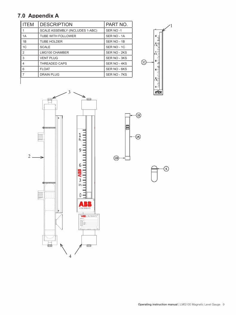
7.0 Appendix A7.1 LMG100 Parts Breakdown Drawing
K-TEK PRODUCTS
K-T
EK P
RO
DUCTS
MADE IN USA LOUISIANA, 70769 TAG0137
K-TEK PRODUCTS
ITEM DESCRIPTION PART NO.1 SCALE ASSEMBLY (INCLUDES 1-ABC) SER NO -1
1A TUBE WITH FOLLOWER SER NO - 1A
1B TUBE HOLDER SER NO - 1B
1C SCALE SER NO - 1C
2 LMG100 CHAMBER SER NO - 2KS
3 VENT PLUG SER NO - 3KS
4 THREADED CAPS SER NO - 4KS
6 FLOAT SER NO - 6KS
7 DRAIN PLUG SER NO - 7KS
4
2
3
1

10 LMG100 Magnetic Level Gauge | Operating instruction manual
8.0 APPENDIX B8.1 Unpacking Unpack the instrument carefully. Inspect all units for damage. Report any concealed damage to carrier within 24 hours. Check the contents of the packing slip and purchase order. Check and record the serial number. This can be used to reference when ordering spare or replacement parts for the MLG and/or related accessories.
Note:Donotdiscardtheshippingcontaineruntilallparts/componentsareverifiedandchecked.
8.2 Pre-Installation Checklist • IfequipmentisusedinamannernotspecifiedbyABB,protectionprovidedbyequipmentmaybe impaired.
• Manuallymovethefloatfrom0%to100%andbackto0%priortostartup/checkoutinordertoreinitializeanyswitch accessories (only required if magnetically actuated switches are supplied). Switches may inadvertently change state during any rough handling during transport.
• Removefloatpriortopressurizingtank/vessel.
Float damage may occur if not removed prior to any pressure testing.
• Verify the MLGs center-to-center dimension equals that of the tank/vessel.
8.3 Equipment & Tools • Open-endwrenchesoranadjustablewrenchtofittheprocessstuds/nuts.Atorquewrenchisalsorecommended.• Flat-blade screwdriver or 5/16” nut driver • Digital multimeter or digital volt/ammeter if transmitters or switches are attached • Level • Gasketformatingflanges• Teflon®(registeredtrademarkofDuPont)tape&“neverseize”forthreadedunits• Pipe wrench for threaded units
8.4 Placing an MLG in Service (Startup) Ensurethattheoperatingconditions(temperature,pressure,andspecificgravity,etc)arewithinthemaximumratingsoftheMLG.AtthebottomareaofeachMLGisanameplatethatindicatesalloftherelevantprocessspecifications,serialnumber,andtagnumber.
Install theMLGfloat(thisshouldhavebeenaccomplishedinpre-installationsteps).Thefloat ismarked“>>>>UP>>>>” to insureproperorientationwhenplacingfloat insidechamber.MLGsaresuppliedwithfloatstartandstopsprings. Verify these are installed at top and bottom locations.
Thefloatchambershouldbeclosedwithnoopeningstotheatmosphere.Checktoseethatalldrainandventplugsare securely in place and all vent and drain valves are closed.
The following procedural sequence is critical in pressurized applications.
When the MLG is mounted and ready to be applied to the liquid service, the TOP processconnection valve should be opened FIRST and should be opened very slowly to allow pressure toequalize.ThisallowsprocessfluidorvaportoentertheMLGataslowandcontrolledratethat
is reasonable and ultimately allows the MLG to reach operating pressure and temperature in a safe fashion.
Operating instruction manual | LMG100 Magnetic Level Gauge 11
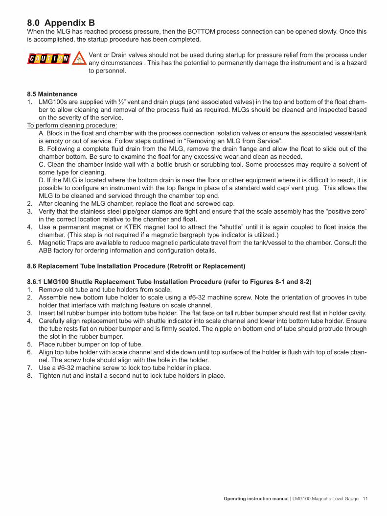
8.0 Appendix B WhentheMLGhasreachedprocesspressure,thentheBOTTOMprocessconnectioncanbeopenedslowly.Oncethisisaccomplished,thestartupprocedurehasbeencompleted.
Vent or Drain valves should not be used during startup for pressure relief from the process under any circumstances . This has the potential to permanently damage the instrument and is a hazard to personnel.
8.5 Maintenance 1. LMG100saresuppliedwith½”ventanddrainplugs(andassociatedvalves)inthetopandbottomofthefloatcham-
bertoallowcleaningandremovaloftheprocessfluidasrequired.MLGsshouldbecleanedandinspectedbasedon the severity of the service.
To perform cleaning procedure: A.Blockinthefloatandchamberwiththeprocessconnectionisolationvalvesorensuretheassociatedvessel/tankis empty or out of service. Follow steps outlined in “Removing an MLG from Service”. B.FollowingacompletefluiddrainfromtheMLG,removethedrainflangeandallowthefloattoslideoutofthechamberbottom.Besuretoexaminethefloatforanyexcessivewearandcleanasneeded.C. Clean the chamber inside wall with a bottle brush or scrubbing tool. Some processes may require a solvent of some type for cleaning. D.IftheMLGislocatedwherethebottomdrainisnearthefloororotherequipmentwhereitisdifficulttoreach,itispossibletoconfigureaninstrumentwiththetopflangeinplaceofastandardweldcap/ventplug.ThisallowstheMLG to be cleaned and serviced through the chamber top end.
2. AftercleaningtheMLGchamber,replacethefloatandscrewedcap.3. Verify that the stainless steel pipe/gear clamps are tight and ensure that the scale assembly has the “positive zero”
inthecorrectlocationrelativetothechamberandfloat.4. UseapermanentmagnetorKTEKmagnettooltoattractthe“shuttle”until it isagaincoupledtofloatinsidethe
chamber. (This step is not required if a magnetic bargraph type indicator is utilized.) 5. Magnetic Traps are available to reduce magnetic particulate travel from the tank/vessel to the chamber. Consult the
ABBfactoryfororderinginformationandconfigurationdetails.
8.6ReplacementTubeInstallationProcedure(RetrofitorReplacement)
8.6.1 LMG100 Shuttle Replacement Tube Installation Procedure (refer to Figures 8-1 and 8-2) 1. Remove old tube and tube holders from scale. 2. Assemble new bottom tube holder to scale using a #6-32 machine screw. Note the orientation of grooves in tube
holder that interface with matching feature on scale channel.3. Inserttallrubberbumperintobottomtubeholder.Theflatfaceontallrubberbumpershouldrestflatinholdercavity.4. Carefully align replacement tube with shuttle indicator into scale channel and lower into bottom tube holder. Ensure
thetuberestsflatonrubberbumperandisfirmlyseated.Thenippleonbottomendoftubeshouldprotrudethroughthe slot in the rubber bumper.
5. Place rubber bumper on top of tube. 6. Aligntoptubeholderwithscalechannelandslidedownuntiltopsurfaceoftheholderisflushwithtopofscalechan-
nel. The screw hole should align with the hole in the holder. 7. Use a #6-32 machine screw to lock top tube holder in place. 8. Tighten nut and install a second nut to lock tube holders in place.

12 LMG100 Magnetic Level Gauge | Operating instruction manual
8.7 LMG100 Shuttle Replacement Glass Installation Procedure
Figure 8-1

Operating instruction manual | LMG100 Magnetic Level Gauge 13
8.9 Lmg100 Shuttle Replacement Glass Installation Procedure
Figure 8-2
RUBBER BUMPERPART NO. MEC24-35
QTY: 1
#6-32 NUTPART NO. NT56-32
QTY: 4
BOTTOM TUBE HOLDERPART NO. KM26-0025
QTY: 1
TOP TUBE HOLDERPART NO. KM26-0026
QTY: 1 REPLACEMENT GLASSWITH SHUTTLE INDICATOR
QTY: 1
TALL RUBBER BUMPERPART NO. MEC24-49
QTY: 1
#6-32 X 2"MACHINE SCREW
PART NO. SRW2X6-32QTY: 2

14 LMG100 Magnetic Level Gauge | Operating instruction manual
9.0 Appendix C9.1 Warranty Statement5 YEAR WARRANTY FOR:KM26 Magnetic Liquid Level Gauges; LMG100 Magnetic Level Gague; MagWave Dual Chamber System; LS Series Mechanical LevelSwitches(LS500,LS550,LS600,LS700,LS800&LS900)(doesNOTincludeswitchingmechanisms,ie.MS30,MS40,MS41,PS35&PS45);ECExternalChambers,STWStillingWellsandST95SealPots.
3 YEAR WARRANTY FOR:KCAP300 & KCAP400 capacitance switches.
2 YEAR WARRANTY FOR:AT100,AT100SandAT200seriestransmitters;RS80andRS85liquidvibratingforkswitches;RLT100andRLT200reedswitchleveltransmitters;TX,TS,TQ,IXandIMthermaldispersionswitches;IR10andPP10ExternalRelays;MT2000,MT5000,MT5100andMT5200radarleveltransmitters;RI100RepeatIndicators;KPpaddleswitches;A02,A75&A77RFcapacitancelevelswitchesandA38RFcapacitanceleveltransmitters;BuoyancyLevelSwitches(MS50,MS10,MS8D&MS8F);MagneticLevelSwitches(MS30,MS40,MS41,PS35&PS45).
1 YEAR WARRANTY FOR:KM50 gauging device; AT500 and AT600 series transmitters; LaserMeter and SureShot series laser transmitters; LPM200 digital indicator; DPM100 digital indicators; APM100 analog indicators; KVIEW series digital indicators and controllers; GRANUPOINT and SLUDGEPOINTvibrating forkswitches,SOLITRAKElectro-MechanicalContinuousMeasuringDevices,KSONIKultrasonic levelswitches,transmitters&transducers,ChuteMasterMicrowaveTransmitter/ReceiverandTiltMasterSwitches.
SPECIAL WARRANTY CONSIDERATIONS:ABB does not honor OEM warranties for items not manufactured by ABB (i.e. Palm Pilots). These claims should be handled directly with the OEM.
ABBwillrepairorreplace,atABB’selection,defectiveitemswhicharereturnedtoABBbytheoriginalpurchaserwithintheperiodspecifiedabovefromtheshipment dateoftheitemandwhichisfound,uponexaminationbyABB,toitssatisfaction,tocontaindefectsinmaterialsorworkmanshipwhicharoseonlyundernormaluseandserviceandwhichwerenottheresultofeitheralterations,misuse,abuse,improperorinadequateadjustments,applicationsorservicingoftheproduct.ABB’swarrantydoesnotcovertherepairorreplacementofunitsthatfailfromtheeffectsofexcessivevibrationunlesstheunitsareoriginallydesignedforvibrationapplication.Inaddition,ABB’s warranty does not include on-site repair or services. Field service rates can be supplied on request.
Ifaproductisbelievedtobedefective,theoriginalpurchasershallnotifyABBandrequestaReturnedMaterialAuthorizationbeforereturning thematerial toABB,with transportationprepaidby thepurchaser. (Toexpediteall returns/repairs fromoutsideof theUnitedStates,consultABB’scustomerserviceteam([email protected])todetermineanoptimalsolutionforshippingmethodandturnaroundtime.)Theproduct,withrepairedorreplacedparts,shallbereturnedtothepurchaseratanypointintheworldwithtransportationprepaidbyABBforbest-waytransportationonly.ABBisnotresponsibleforexpeditedshippingcharges.IftheproductisshippedtoABBfreightcollect,thenitwillbereturnedtothecustomerfreightcollect.
IfinspectionbyABBdoesnotdiscloseanydefectsinmaterialorworkmanship,ABB’snormalchargesforrepairandshipmentshallapply(minimum250.00USD).ThematerialsofconstructionforallABBproductsareclearlyspecifiedanditistheresponsibilityofthepurchaser to determine the compatibility of the materials for the application.
THE FOREGOINGWARRANTY ISABB’S SOLEWARRANTYANDALL OTHERWARRANTIES EXPRESSED, IMPLIED, ORSTATUTORY,INCLUDINGANYIMPLIEDWARRANTYOFMERCHANTABILITYOFFITNESSFORAPARTICULARPURPOSE,ARE EXCLUDED AND NEGATED TO THE MAXIMUM EXTENT PERMITTED BY LAW. NO PERSON OR REPRESENTATIVE IS AUTHORIZED TO EXTEND ANY OTHER WARRANTY OR CREATE FOR ABB ANY OTHER LIABILITY IN CONNECTION WITH THE SALE OF ABB’S PRODUCTS. THE REMEDIES SET FORTH IN THIS WARRANTY ARE EXCLUSIVE OF ALL OTHER REMEDIES AGAINSTABB. ABBSHALLNOTBELIABLEFORANYCONSEQUENTIAL, INCIDENTAL,ORSPECIALDAMAGESOFANYKIND. ABB’S SOLE OBLIGATION SHALL BE TO REPAIR OR REPLACE PARTS (FOUND TO BE DEFECTIVE IN MATERIALS OR WORKMANSHIP) WHICH ARE RETURNED BY THE PURCHASER TO ABB.
Operating instruction manual | LMG100 Magnetic Level Gauge 15
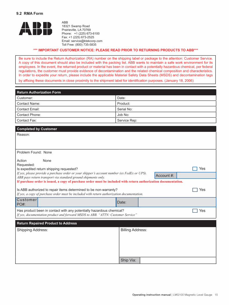
9.2 RMA Form
ABB18321 Swamp RoadPrairieville,LA70769Phone: +1 (225) 673-6100Fax:+1(225)673-2525Email:[email protected] Free: (800) 735-5835
*** IMPORTANT CUSTOMER NOTICE: PLEASE READ PRIOR TO RETURNING PRODUCTS TO ABB***
Be sure to include the Return Authorization (RA) number on the shipping label or package to the attention: Customer Service. A copy of this document should also be included with the packing list. ABB wants to maintain a safe work environment for its employees.Intheevent,thereturnedproductormaterialhasbeenincontactwithapotentiallyhazardouschemical,perfederalregulations,thecustomermustprovideevidenceofdecontaminationandtherelatedchemicalcompositionandcharacteristics.Inordertoexpediteyourreturn,pleaseincludetheapplicableMaterialSafetyDataSheets(MSDS)anddecontaminationtagsbyaffixingthesedocumentsincloseproximitytotheshipmentlabelforidentificationpurposes.(January18,2006)
Return Authorization FormCustomer: Date:Contact Name: Product:Contact Email: Serial No:Contact Phone: JobNo:ContactFax: Service Rep:
Completed by CustomerReason:
Problem Found: None
Action NoneRequested:Isexpeditedreturnshippingrequested?If yes, please provide a purchase order or your shipper’s account number (ex FedEx or UPS). ABB pays return transport via standard ground shipments only.If purchase order is issued, a copy of purchase order must be included with return authorization documentation.
IsABBauthorizedtorepairitemsdeterminedtobenon-warranty?If yes, a copy of purchase order must be included with return authorization documentation.
Hasproductbeenincontactwithanypotentiallyhazardouschemical?If yes, documentation product and forward MSDS to ABB. “ATTN: Customer Service”
Account #:
Yes
Yes
Yes
Customer PO#: Date:
Return Repaired Product to Address
Shipping Address:
Billing Address:
Ship Via:

OI/
LMG
100-
EN
0
5.20
14
Contact us
ABB Inc. 18321 Swamp RoadPrairieville, LA 70769 USAPhone: +1 225 673 6100Service: +1 225 677 5836Fax: +1 225 673 2525E-mail: [email protected] e-mail: [email protected]
ABB Inc.585, Boulevard Charest E., Suite 300Quebec, QC Canada G1K 9H4Phone: +1 418 877 2944Service: +1 800 858 3847Fax: +1 418 877 2834E-mail: [email protected] e-mail: [email protected]
ABB Engineering (Shanghai) Ltd.No. 5, Lane 369, Chuangye RoadKangqiao Town, Pudong District Shanghai, 201319, P.R. ChinaPhone: +86 10 64231407Service: +86 21 61056421Fax: +86 10 64371913E-mail: [email protected] e-mail: [email protected]
ABB LimitedSalterbeck Trading EstateWorkington, Cumbria, England CA14 5DSPhone: +44 7885333752Service: +44 145 3826661E-mail: [email protected] e-mail: [email protected]
www.abb.com/level
NoteWe reserve the right to make technical changes or modify the contents of this document without prior notice. With regard to purchase orders, the agreedparticulars shall prevail. ABB does not accept any responsibility whatsoever for potential errors or possible lack of information in this document.
We reserve all rights in this document and in the subject matter and illustrations contained therein. Any reproduction, disclosure to third parties or utilization of its contents - in whole or in parts – is forbidden without prior written consent of ABB.
Copyright© 2014 ABBAll rights reserved
Sales
Service