manual vbp-hh1-v3.0* - pepperl+fuchs
TRANSCRIPT

VBP-HH1-V3.0*AS-Interface handheld
FACTORY AUTOMATION
MANUAL

With regard to the supply of products, the current issue of the following document is applicable: The General Terms of Delivery for Products and Services of the Electrical Industry, published by the
Central Association of the Electrical Industry (Zentralverband Elektrotechnik und Elektroindustrie (ZVEI) e.V.) in its most recent version as well as the supplementary clause: "Expanded reservation
of proprietorship"
VBP-HH1-V3.0*

VBP-HH1-V3.0*Contents
201
3-06
3
1 Declaration of Conformity ................................................. 42 Safety................................................................................... 5
2.1 Used Symbols.................................................................................. 52.2 General safety instructions ............................................................... 5
3 Notes on disposal............................................................... 64 Product Description ........................................................... 7
4.1 AS-Interface Specification 3.0 .......................................................... 74.2 Use and application of the handheld ................................................ 84.3 Delivery package.............................................................................. 84.4 Displays and controls ....................................................................... 9
4.4.1 AS-Interface-Anschlussadapter ..............................................................104.4.2 LC display ..............................................................................................104.4.3 Button assignment..................................................................................124.4.4 Button combinations...............................................................................124.4.5 Connections ...........................................................................................12
4.5 Accessories.................................................................................... 134.5.1 External power supply ............................................................................134.5.2 Programming cable ................................................................................13
5 Commissioning................................................................. 145.1 Preparation..................................................................................... 145.2 Storage and transport..................................................................... 15
6 Operation........................................................................... 166.1 Addressing operating mode ........................................................... 166.2 Read ID operating mode ................................................................ 176.3 Read/write ID1 operating mode...................................................... 176.4 Read ID2 operating mode .............................................................. 186.5 Read IO operating mode ................................................................ 186.6 Read Peripheral Fault operating mode ........................................... 186.7 Set Slave Parameter operating mode ............................................. 196.8 Read/write Slave Data operating mode .......................................... 19
7 Error messages ................................................................ 228 Technical data................................................................... 23
201
3-06
4
VBP-HH1-V3.0*Declaration of Conformity
1 Declaration of ConformityAll products were developed and manufactured under observance of the applicable European standards and guidelines.
The product manufacturer, Pepperl+Fuchs GmbH, 68307 Mannheim, has a certified quality assurance system that conforms to ISO 9001.
Note!A Declaration of Conformity can be requested from the manufacturer.
ISO9001

VBP-HH1-V3.0*Safety
201
3-06
5
2 Safety2.1 Used Symbols
Safety-relevant Symbols
Informative Symbols
ActionThis symbol indicates a paragraph with instructions.
2.2 General safety instructionsInstallation and commissioning of all devices must be performed by a trained professional only.This device is approved for use in environments with controlled electromagnetic compatibility (EMC) according to IEC 61326-1. Jammers, such as mobile phones can not be operated in close proximity.Protection of operating personnel and the system is not ensured if the product is not used in accordance with its intended purpose.Only use recommended original accessories.User modification and or repair are dangerous and will void the warranty and exclude the manufacturer from any liability. If serious faults occur, stop using the device. Secure the device against inadvertent operation. In the event of repairs, return the device to your local Pepperl+Fuchs representative or sales office. When packing the device for storage or transport, use materials that will protect the device from bumps and impacts and protect against moisture. The original packaging provides the best protection. Also take into account the permitted ambient conditions.
Danger!This symbol indicates an imminent danger.Non-observance will result in personal injury or death.
Warning!This symbol indicates a possible fault or danger.Non-observance may cause personal injury or serious property damage.
Caution!This symbol indicates a possible fault.Non-observance could interrupt devices and any connected facilities or systems, or result in their complete failure.
Note!This symbol brings important information to your attention.

201
3-06
6
VBP-HH1-V3.0*Notes on disposal
3 Notes on disposalElectronic waste is hazardous waste. When disposing of the equipment, observe the current statutory requirements in the respective country of use, as well as local regulations. Do not dispose of storage batteries with the household refuse.
Consumers are obliged by law to dispose of used storage batteries in accordance with regulations. You can hand in your used batteries at public collection points in your area or sales points where batteries of that particular kind are sold. You can also send your used batteries directly to us for disposal. Please remember that this service is only available within the scope of normal use. If you wish to send back your used batteries, please affix sufficient postage stamps and send to our address. There are no extra charges for disposal.

VBP-HH1-V3.0*Product Description
201
3-06
4 Product Description4.1 AS-Interface Specification 3.0
In 2004, the AS-Interface Association defined the AS-Interface Specification 3.0 as a backwards-compatible extension, while retaining the protocol and physical structure. AS-Interface Specification 3.0 gives the user important advantages:
■ The number of possible network slaves is increased to 62. This is accomblished by enabling 31 A addresses and 31B addresses of which each is able to support up to 4 output databits.In the master message of Specification 3 the I3 output bit has been replaced by the SEL select bit. This select bit enables, in addition to the address bits A0 to A4, differentiation in the address areas A and B. Through this differentiation, any address can be distributed in both A and B, e.g. the address 15A and 15B.In Specification 2.1 3 output bits are available per AS-Interface slave. In Specification 3.0, through the definition of the multiplex bit in place of the I2 bit, 4 output bits are available per slave(communication of 4 output bits in succession via the data bits I1 and I0), i.e. a total of 4*62=248 output bits. The slave message remains unaffected by this change, i.e. there are still 4*62=248 input bits available. In practice, this means an increase of the cycle time to a max. 20 ms, since in the 1st cycle the data of the AS-Interface slaves in the address area A, and in the 2nd cycle, the data of the respective AS-Interface slaves in the address area B are written and read. Additionally, the output bits are transferred one after the other.Due to the backwards compatibility of Specification 3.0 you can continue to use standard AS-Interface slaves. However, two of the 62 possible addresses are occupied by a standard AS-Interface slave.
Structure of the master message
■ Extended diagnostic functionIn addition to communication faults (e.g. messages with errors), the AS-Interface master also detects hardware faults that are present on the AS-Interface slave. You have the option of utilizing these peripheral error messages to provide a defined system shutdown in the event of a fault, since sensor signals are no longer guaranteed to be available. In addition, a statistical evaluation of the data is conceivable in order to assess the safety of the system. Also, because of the extended diagnostics, it is possible to locate sporadically occurring faults with regard to configuration and communication and to evaluate them via the AS-I Control Tools.
SB CB A4 A3 A2 A1 A0 I4 SEL MUX I1 I0 PB EB
Note!You have the option of reducing the cycle time by reducing the number of AS-Interface slaves or by addressing the A/B-Slaves in the standard mode.
7

VBP-HH1-V3.0*Product Description
201
3-06
■ Extension of the ID-Codes of the AS-Interface slaves.Specification 2.1 AS-Interface slaves (A/B slaves) have the hexadecimal value A as the ID-Code and have 2 more identification codes (ID1 and ID2) that describe the functionality of the slave. You have the option of describing the ID1-Code.The ID-Code for standard AS-Interface slaves differs from the ID-Code of the A/B slaves. With standard AS-Interface slaves, no further identification codes are included.
4.2 Use and application of the handheldAS-Interface slaves are usually addressed with a handheld. As a rule, a number of steps are necessary to address the slaves and in the future you will be able to execute this procedure faster using the handheld:
■ Unique addressing of the AS-Interface slaves■ Power supply to the AS-Interface slaves via the handheld■ Function checks – even without programmable logic controller (PLC)
4.3 Delivery packageThe delivery package contains:
Figure 4.1 1) = VBP-HH1-V3.0-KIT-110V only
Note!If you have changed the ID1-Code and want to automatically program the address, check before the installation of the new AS-Interface slave that the ID1-Code has been correctly stored in the AS-Interface slave.
VBP-HH1-V3.0VBP-HH1-V3.0-110V
VBP-HH1-V3.0-KITVBP-HH1-V3.0-KIT-110V
■ Addressing device■ Charger■ Quick start guide
■ Addressing device■ Charger■ Quick start guide■ Case■ Four programming cables:
VAZ-PK-1.5M-V1-G1, V1S-G-1M-PUR1), V1-G-0.3M-PUR-V1-G1) and VAZ-PK-FK-0.2M-V1-W 1)
8

VBP-HH1-V3.0*Product Description
201
3-06
4.4 Displays and controls
1 AS-Interface connection adapter2 LC Display3 up arrow button4 down arrow button5 PRG button6 ADR button7 Charger connector8 Mode button
2
3
4
6
5
1
8
7
9

VBP-HH1-V3.0*Product Description
201
3-06
4.4.1 AS-Interface-Anschlussadapter
Figure 4.2
The AS-Interface connection adapter on the top of the addressing device is used to connect AS-Interface nodes (sensors, actuators, and interface modules) to the addressing device. The following devices and models can be connected directly to the addressing device by plugging into the AS-Interface connecting adapter:
■ Devices with M12 plug■ VariKont M-System■ VariKont-System■ FP models■ AS-Interface modules (*-G1, *-G4, *-G16)
For models with an integrated addressing jack, please use the VAZ-PK-1.5M-V1-G adapter cable.The addressing device supplies the connected AS-Interface node with up to 28 V voltage (25 V 100 mA). If this voltage is not sufficient, you have the option of using an external power supply for the AS-Interface node. In this case, the internal power supply is cut off by the addressing device.
4.4.2 LC display
1 Address and data display2 Address field3 Operating mode display
ADDRID12IO
DATAPARAPERI
RDWR A
B1 2 3 4 5 6 7 8 9 10 11 12 13 14 16 16 1718 19 20 21 22 23 24 25 26 27 28 29 30 31
AB
3
1
2
10

VBP-HH1-V3.0*Product Description
201
3-06
Address and data displayDepending on the operating mode, two digits and the letters A and B are used to display various information in this area of the display.
■ The address of the currently selected AS-Interface node differs according to the AS-Interface specification supported and the address areas Standard (shown without letters), A and B.
■ Target address which is to be communicated to the currently selected AS-Interface node
■ Display of read data■ Display of data to be written
Address fieldAll the AS-Interface nodes of the AS-Interface network are shown in this area of the display:
■ If the addressing device detects AS-Interface nodes from various address areas, the various address areas are identified in the right-hand section of the address field, as follows:
• Without letters: For AS-Interface nodes that do not support the AS-Interface specification 2.1.
• A: For AS-Interface nodes belonging to address area A.• B: For AS-Interface nodes belonging to address area B.
The display of the detected addresses in the respective address area changes every 2 seconds.
■ The addresses of all AS-Interface nodes currently connected to the addressing device are shown in the Addressing operating mode by flashing digits. In all other operating modes, the addresses of the AS-Interface nodes shown flashing are those being actively accessed.
■ During Addressing, the non-flashing digits represent addresses of AS-Interface nodes that have been assigned addresses by the addressing device.
Operating mode displayThe current operating mode is shown in this area of the display.
11

VBP-HH1-V3.0*Product Description
201
3-06
4.4.3 Button assignment
4.4.4 Button combinations
4.4.5 ConnectionsThe addressing device uses the following connections:
■ Connection socket for the power supply to charge the internal battery on the underside of the addressing device.
■ M12 socket on the AS-Interface connection adapter with the following pinning:
• Pin 1: AS-Interface+• Pin 2: Digital input for optical addressing adapter• Pin 3: AS-Interface-• Pin 4: Digital output for optical addressing adapter• Pin 5: Power supply for optical addressing adapter
■ Several individual AS-Interface+/- sockets on the AS-Interface connection adapter for connection of AS-Interface nodes.
Button DescriptionSet values (e.g.slave address, ID1 data, slave parameters, slave data), change of operating modeSet values (e.g. slave address, ID1 data, slave parameters, slave data)The function depends on the operating mode:■ transfer of a new slave address to the slave (ADDR)■ transfer of ID1 data (ID1)■ transfer of slave parameters (PARA)■ transfer of slave data (DATA)Switch on addressing device, search and read out slave addressesDouble click: switch off addressing deviceChange between operating modes
PRG
ADR
MODE
Button combinations Description
& Function dependent on the duration of pressing:■ Short press: address 0 is assigned to the connected slave■ Long press: the list of assigned slaves is deleted
& or Navigate through source addresses of several slaves connected to the addressing device
& or Navigate through the operating modes
ADR PRG
ADR
MODE
1
4 2
35
12

VBP-HH1-V3.0*Product Description
201
3-06
4.5 AccessoriesVarious accessories are available.
4.5.1 External power supply
4.5.2 Programming cable
Product Product nameVAN-115/230AC-K21-EFD AS-Interface power supplyV1S-TEE-V1/V1S T-splitter for the connection of an external power
supply (V1 plug) and an AS-Interface node (M12 socket)
V1-W-2M-PVC Cable with V1 socket and open end for connection of the power supply
Product Product nameVAZ-PK-1.5M-V1-G Extension cable for module/handheld programming
unit
13
VBP-HH1-V3.0*Commissioning
201
3-06
5 Commissioning5.1 Preparation
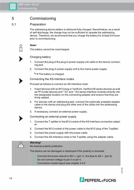
The addressing device battery is delivered fully charged. Nevertheless, as a result of self-discharge, the charge may not be sufficient to operate the addressing device. Therefore, we recommend that you charge the battery for at least 24 hours prior to commissioning.
Charging battery1. Connect the plug of the plug-in power-supply unit cable to the device connect-
ing jack.2. Connect the plug-in power-supply unit to the mains power supply.
The battery is charged.Connecting the AS-Interface nodesProceed as follows to connect an AS-Interface node:1. Insert devices with an M12 plug or VariKont, VariKont M series devices as well
as FP model devices and *-G1 and *-G4 series interface modules directly into the designated location on the connecting adapter and ensure that they are firmly seated.
2. For devices with an addressing jack, connect the optionally available adapter cable to the device and plug the other end of the cable into the addressing device.
3. If necessary, connect an external power supply.Connecting an external power supply1. Connect the T-splitter to the M12 socket of the AS-Interface connection adapt-
er.2. Connect the M12 socket of the power cable to the M12 plug of the T-splitter.3. Connect the power supply with the power cable.4. Connect the AS-Interface node to the T-splitter using the adapter cable.
Note!The battery cannot be overcharged.
Warning!No reverse polarity protectionThe device can be damaged or destroyed if the polarity is reversed.
■ Connect the brown strand to AS-i + (pin 1), the blue to AS-i - (pin 3).■ Do not connect voltage to pin 2 or pin 4.■ Connection socket layout see chapter 4.4.5
14
VBP-HH1-V3.0*Commissioning
201
3-06
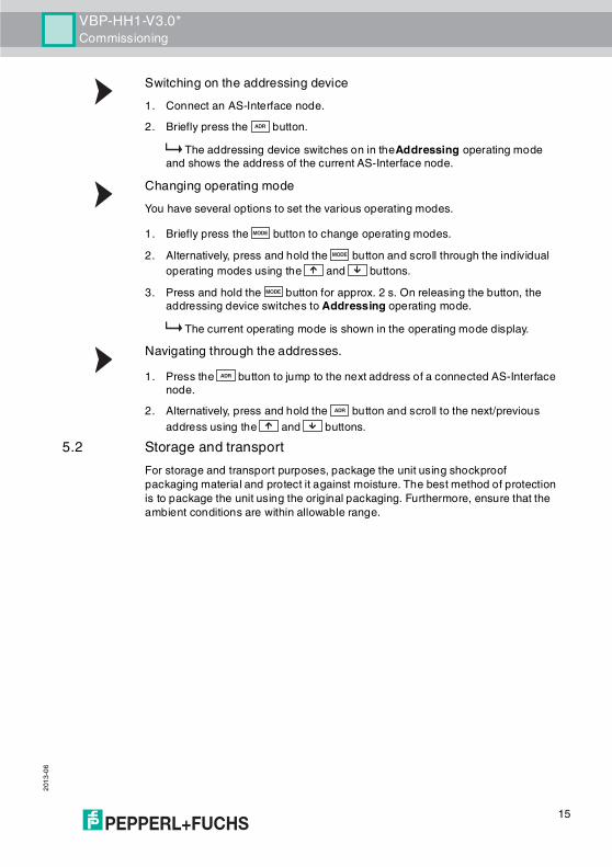
Switching on the addressing device1. Connect an AS-Interface node.2. Briefly press the button.
The addressing device switches on in theAddressing operating mode and shows the address of the current AS-Interface node.
Changing operating modeYou have several options to set the various operating modes.
1. Briefly press the button to change operating modes.2. Alternatively, press and hold the button and scroll through the individual
operating modes using the and buttons.3. Press and hold the button for approx. 2 s. On releasing the button, the
addressing device switches to Addressing operating mode. The current operating mode is shown in the operating mode display.
Navigating through the addresses.1. Press the button to jump to the next address of a connected AS-Interface
node.2. Alternatively, press and hold the button and scroll to the next/previous
address using the and buttons.5.2 Storage and transport
For storage and transport purposes, package the unit using shockproof packaging material and protect it against moisture. The best method of protection is to package the unit using the original packaging. Furthermore, ensure that the ambient conditions are within allowable range.
ADR
MODE
MODE
MODE
ADR
ADR
15
VBP-HH1-V3.0*Operation
201
3-06
6 Operation6.1 Addressing operating mode
The addressing is divided into 3 individual procedures. The following table shows the individual processes:
Navigating through addresses / selecting source address when several slaves are connectedPress the button to select the AS-Interface slave to which you want to assign a new address. If several AS-Interface slaves are connected to the addressing device, press the button several times or press and hold the button and scroll through the addresses using the and buttons.Synonymous use of standard and A addresses
1. To assign an address to a connected slave with or without extended address-ing, it is sufficient to specify a target address in the standard address area or in address area A. For a slave without extended addressing, the addressing device assigns the set address automatically in the standard address area. For a slave with extended addressing, the addressing device assigns the set address automatically as an A address.
2. To assign an address in address area B, you must specify target address area B. See "Setting the target address" on page 17. If a slave without extended addressing is connected, the addressing device shows a fault message.
Note!When addressing AS-Interface slaves connected to the handheld, make sure that the address 0 is not occupied. Otherwise, an error message may occur.
Procedure AddressingSelecting the source address
■ one AS-Interface slave connected: The address of the connected AS-Interface slave is automatically detected as the source address.
■ several AS-Interface slaves connected: The source address must be manually selected, see "Navigating through addresses / selecting source address when several slaves are connected" on page 16.
Selection of target address See "Setting the target address" on page 17When being addressed, if the target address is occupied by a further connected AS-Interface slave, the addressing device issues an error message.
Start addressing See "Starting addressing" on page 17
ADR
ADR ADR
Note!When addressing a slave, the address area of the target address is automatically adapted to the connected slave:
16

VBP-HH1-V3.0*Operation
201
3-06
Setting the target addressSet the target address using the and buttons.
Starting addressingBriefly press the button to start addressing.Deleting the list of assigned addressesTo delete the list of assigned addresses, press and hold the and buttons simultaneously for approx. 2 s.Assigning address 0 to slaveTo assign address 0 to a connected slave, press and briefly hold the buttons and simultaneously.
6.2 Read ID operating modeAs soon as you switch to the Read ID operating mode, the ID code of the active AS-Interface slave is read in and shown in the address and data display. The value of the ID-Code is always Afor A/B Slaves.Repeat readingTo repeat the reading of the code, press the button.
6.3 Read/write ID1 operating mode
As soon as you switch to the Read/write ID1 operating mode, the ID1 code of the active AS-Interface slave is read in and is shown in the address and data display.Repeat readingTo repeat the reading of the code, press the button.
TipAddresses marked as occupiedThe already assigned addresses are stored in the addressing device in a list of assigned addresses and shown in the address field of the display as a non-flashing number. This list is available after restarting the addressing device. You can therefore avoid duplicate addressing.
PRG
PRG ADR
PRG
ADR
ADR
Note!AS-Interface Specification 2.1This function applies only to AS-Interface slaves that support Specification 2.1.
ADR
17

VBP-HH1-V3.0*Operation
201
3-06
Write ID1 Code
To write an ID1 Code to the active AS-Interface slave, proceed as follows:
1. Set the desired value for the ID1 Code with the and buttons. The RDdisplay goes out when scrolling up and down.
2. Press the button to write the desired value permanently to the active AS-Interface slave,.
WRappears in the operating mode display.6.4 Read ID2 operating mode
As soon as you switch to the Read ID2 operating mode, the ID2 code of the active AS-Interface slave is read in and is shown in the address and data display. It is not possible to change this value.Repeat readingTo repeat the reading of the code, press the button.
6.5 Read IO operating modeAs soon as you switch to the Read IO operating mode, the IO code of the active AS-Interface slave is read in and is shown in the address and data display.Repeat readingTo repeat the reading of the code, press the button.
6.6 Read Peripheral Fault operating modeAs soon as you switch to the Read Peripheral Fault operating mode, the address and data display indicates if there is a peripheral fault on the AS-Interface slave. A peripheral fault is present if the value 1 is displayed. The cause of the fault depends on the AS-Interface slave being used.Repeat readingTo repeat the reading of the code, press the button.
Note!The value of the ID1 Code ranges from 0 to 15 for standard AS-Interface slaves and from 0 to 7 for A/B slaves.
PRG
Note!AS-Interface Specification 2.1This function applies only to AS-Interface slaves that support Specification 2.1.
ADR
ADR
ADR
18

VBP-HH1-V3.0*Operation
201
3-06
6.7 Set Slave Parameter operating modeIn the operating mode Read/write slave data, the slave parameter value activates the data transmission from the addressing device to the AS-Interface slave. The standard value is 15 for standard AS-Interface slaves and 7 for A/B slaves.The set data value is retained until:
■ You change the active address in the Addressing operating mode,■ You replace the AS-Interface slaves which have the same address but
different ID, ID2, or IO codes.■ The addressing device is automatically switched off or manually switched
off after a long period without use.You must adapt the corresponding slave parameters according to the AS-Interface slave used. Set parameters1. Set the desired slave parameter value with the and buttons.
By scrolling up and down, the RDdisplay goes out.2. Press the button.
WRappears in the operating mode display. The parameter value is temporarily accepted, but not transferred to the slave.
6.8 Read/write Slave Data operating mode
Setting and sending output data1. Set the desired output data value using the and buttons.
The RD display goes out when scrolling.2. To temporarily save the desired output data value and transmit it once to the
active AS-Interface slave, briefly press the button. If you want to execute a cyclic output data exchange, you must (for security reasons) press and hold the button. The output data value is cyclically transmitted to the AS-Interface slave until you release the button.
WRappears in the operating mode display. The output data value is 0 as standard.
PRG
button is pressed briefly Send previously set output data once to an AS-Interface slave/display set output data
button pressed and held Cyclic sending of previously set output data
button is pressed briefly Read out input data once from the AS-Interface slave and send previously set output data to the AS-Interface slave.
button pressed for 2 seconds.
Cyclic reading of the input data, cyclic sending of previously set output data.
PRG
PRG
ADR
ADR
PRG
PRG
19

VBP-HH1-V3.0*Operation
201
3-06
The set output data value is temporarily stored in the handheld. The output data value is shown on the display as long as you do not press the , or buttons. If the displayed output data value deviates from the stored output data after pressing the button, then:
1. press the button once. The set output data are shown and the RD goes out.
2. Set the desired output data value if necessary using the and buttons or
3. briefly press the button to temporarily save the set output data value and transmit it once to the active AS-Interface slave.
The set data value is retained until:■ You change the active address in the Addressing operating mode,■ You replace the AS-Interface slaves which have the same address but
different ID, ID2, or IO codes.■ The addressing device is automatically switched off or manually switched
off after a long period without use.Reading data from the AS-Interface slave
To read the input data from the AS-Interface slave, briefly press the button. If you press the button for at least 2 seconds, the input data from the AS-Interface slave is cyclically read and the output data from the addressing device is sent to the AS-Interface slave. This continues until you press any button on the addressing device. The addressing devices does not switch itself off.Complex communication protocolsThe addressing device supports the following complex communication protocols:
■ AS-Interface slaves with the profile S-7.A.7 are detected as AS-Interface slaves with extended addressing and 4 inputs and 4 outputs and are correctly handled.
■ AS-Interface slaves with the Profile S-0.B and S-7.B are detected as AS-Interface slaves and handled in accordance with AS-Interface at Work.
TipChecking output dataYou can check the set output data by briefly pressing the or button. The set output data are displayed. No data is transferred to the slave.
ADR
ADR
PRG
PRG
Note!When input data are read from the AS-Interface slave, the output data and/or parameter values are also automatically transmitted from the addressing device to the AS-Interface slave. Check that these values do not endanger the trouble-free operation of your plant.
ADR
ADR
20

VBP-HH1-V3.0*Operation
201
3-06
All other complex communication protocols are not supported and are handled by the addressing device as standard AS-Interface slaves.Safety Code (AS-Interface Safety At Work)As soon as both input channels of an AS-Interface safety slave are active, a cyclic sequence of 8 x 4 bits is transmitted to the addressing device. These data are designated as the Safety-Code. The Safety-Code is defined as follows:
The Safety-Code always starts with the data packet 00zz. Thus this denotes the start of a new safety code. The two y-bits of the following data packets are never simultaneously 0. The two x-bits of the following data packets are 00. Read Safety-Code (AS-Interface Safety at Work)Reading Safety-Codes is supported by this addressing device. To be able to read Safety-Codes, proceed as follows:1. Make sure that the two input channels of the AS-Interface safety slaves are ac-
tive.2. Press the button.
Each time the button is pressed, the hexadecimal value of the respective data packet of the Safety-Code, beginning with the first data packet 00zz, is shown in the address and data display.
Cycle Structure of the data packet1 00zz2 yyxx3 yyxx4 yyxx5 yyxx6 yyxx7 yyxx8 yyxx
ADR
21

201
3-06
22
VBP-HH1-V3.0*Error messages
7 Error messagesThe following messages can appear in the addressing device display.
Error code Meaning Description RemedyF1 AS-Interface overload Current consumption of
the AS-Interface slaves connected to the addressing device is too high.
Connect an external power supply.
F2 Slave not found No AS-Interface slave has been found at the active address
Check the address or connect an AS-Interface slave.
F3 Programming error When programming the address or the IDI code, the value could not be permanently stored in the AS-Interface slave’s EEPROM.
If necessary, repeat the programming.
F4 Target address occupied
The target address, to which the current AS-Interface slave is to be reprogrammed, is occupied.
Assign a different address to the active AS-Interface slave.
F5 Address 0 occupied Address 0 is occupied by another AS-Interface slave
Make sure that address 0 is not occupied.
F6 Standard AS-Interface slave found instead of the A/B-Slave
The standard operation cannot be executed because the active AS-Interface slave does not satisfy the specification 2.1
You cannot use the Read IO, Set slave parameters, and Read/write slave data operating modes with the currently connected standard AS-Interface slave.
F7 A-/B slave found instead of the standard AS-Interface slave
The active standard AS-interface slave has been replaced by an A-/B slave
Assign an address to the A-/B-Slave in the corresponding address area A or B.
F8 Reception error Due to a fault, the AS-Interface slave response could not be correctly received
Carry out the action again.

VBP-HH1-V3.0*Technical data
201
3-06
8 Technical data
Figure 8.1
General specifications
Indicators/operating means
Electrical specifications
Interface
VBP-HH1-V3.0 VBP-HH1-V3.0-110VOperating mode plug-in charging unit, 230 V
AC, included in the delivery package
Power adapter 120 V AC, included with delivery
AS-Interface specification
V3.0
Display LC displayKeyboard membrane keys, 5 keys
Operating duration 8 h or 250 read/write procedures for fully charged batteryPower supply battery mode, please use only battery charger included with
delivery to charge (charging time about 14 h)
Interface type AS-Interface, short-circuit proof and overload-proof, or opticalOpen loop voltage 28 VLoad current 100 mA at 25 V
23

VBP-HH1-V3.0*Technical data
201
3-06
Compliance with standards and directives
Ambient conditions
Mechanical specifications
Directive conformityLow Voltage Directive 2006/95/EC
EN 61558-1:2005 , EN 61558-2-6:1997
EMC Directive 2004/108/EC
EN 61326-1:2006 , EN 61000-6-4:2007
Standard conformityNoise immunity EN 61326-1:2006Emitted interference EN 61000-6-4:2007Protection degree EN 60529:2000
Ambient temperature 0 ... 40 °C (32 ... 104 °F)Storage temperature -20 ... 40 °C (-4 ... 104 °F)
Protection degree IP20MaterialHousing plasticMass approx. 275 g
24

VBP-HH1-V3.0*Technical data
201
3-06
25

Subject to modificationsCopyright PEPPERL+FUCHS • Printed in Germany
www.pepperl-fuchs.com
FACTORY AUTOMATION – SENSING YOUR NEEDS
Worldwide HeadquartersPepperl+Fuchs GmbH68307 Mannheim · GermanyTel. +49 621 776-0E-mail: [email protected]
USA HeadquartersPepperl+Fuchs Inc.Twinsburg, Ohio 44087 · USATel. +1 330 4253555E-mail: [email protected]
Asia Pacific HeadquartersPepperl+Fuchs Pte Ltd.Company Registration No. 199003130ESingapore 139942Tel. +65 67799091E-mail: [email protected]
TDOCT-0159E_ENG06/2013