mapware-7000 ladder logic guide - prime controls co ...€¦ · multiplexer a particular register...
TRANSCRIPT
1010-1041 rev. 00
MAPware-7000
Ladder Logic Guide
© 2011 Maple Systems Inc. All rights reserved.
Maple Systems Inc.
808 134th
Street SW, Suite 120
Everett, WA 98204-7333
Phone: (425) 745-3229
Email: [email protected]
Web: www.maplesystems.com


i MAPware-7000 Ladder Logic Guide
1010-1041 rev. 00
Table of Contents Logic Block Instructions ................................................................................................................... 1
Overview ...................................................................................................................................... 1
Ladder Instruction Table.............................................................................................................. 1
Input/Output Instructions ........................................................................................................... 1
Data Transfer Instructions ........................................................................................................... 2
Math Instructions ........................................................................................................................ 4
Compare Instructions .................................................................................................................. 5
Logic Instructions ......................................................................................................................... 6
Conversion Instructions ............................................................................................................... 8
Timer Instructions ....................................................................................................................... 9
Counter Instructions .................................................................................................................. 10
Program Control Instructions .................................................................................................... 10
Functions Instructions ............................................................................................................... 11
Special Instructions.................................................................................................................... 12
Instructions Defined .................................................................................................................. 14
Instruction 1- NO Contact ...................................................................................................... 14
Instruction 2- NC Contact ...................................................................................................... 15
Instruction 3- Output ............................................................................................................. 16
Instruction 4- Rising Edge (Transitional Contact) .................................................................. 17
Instruction 5- Falling Edge (Transitional Contact) ................................................................. 18
Instruction 6- Forced Coil ...................................................................................................... 19
Instruction 7- Inverter ........................................................................................................... 20
Instruction 8- Inverter Coil .................................................................................................... 21
Instruction 9- Positive Pulse Contact ..................................................................................... 22
Instruction 10- Negative Pulse Contact ................................................................................. 23
Instruction 11- Positive Pulse Coil ......................................................................................... 24
Instruction 12- Negative Pulse Coil ....................................................................................... 25
Instruction 13- MOV Word .................................................................................................... 26
Instruction 14- MOV DWord.................................................................................................. 28
MAPware-7000 Ladder Logic Guide ii
1010-1041 rev. 00
Instruction 15- Invert Transfer .............................................................................................. 29
Instruction 16- Table Initialize ............................................................................................... 30
Instruction 17- Table Block Transfer ..................................................................................... 31
Instruction 18- Table Invert Transfer ..................................................................................... 32
Instruction 19- Data Exchange .............................................................................................. 33
Instruction 20- Multiplexer.................................................................................................... 34
Instruction 21- Demultiplexer ............................................................................................... 36
Instruction 22- Addition ........................................................................................................ 38
Instruction 23- Double-Word Addition.................................................................................. 40
Instruction 24- Subtraction.................................................................................................... 42
Instruction 25- Double-Word Subtraction ............................................................................. 44
Instruction 26- Multiplication ................................................................................................ 47
Instruction 27- Unsigned Multiplication ................................................................................ 48
Instruction 28- Division.......................................................................................................... 50
Instruction 29- Unsigned Division ......................................................................................... 52
Instruction 30- Division – Double Word ................................................................................ 55
Instruction 31- Addition with carry ....................................................................................... 57
Instruction 32- Subtraction with carry .................................................................................. 59
Instruction 33- Increment...................................................................................................... 61
Instruction 34- Decrement .................................................................................................... 62
Instruction 35- Greater Than ................................................................................................. 63
Instruction 36- Double Word Greater Than .......................................................................... 64
Instruction 37- Unsigned Word Greater Than ....................................................................... 66
Instruction 38- Greater Than or Equal To .............................................................................. 67
Instruction 39- Double Word Greater Than or Equal To ....................................................... 69
Instruction 40- Unsigned Greater Than or Equal To .............................................................. 71
Instruction 41- Equal To ........................................................................................................ 73
Instruction 42- Double Word Equal To .................................................................................. 75
Instruction 43- Unsigned Equal To ........................................................................................ 77
Instruction 44- Not Equal To ................................................................................................. 79
Instruction 45- Double Word Not Equal To ........................................................................... 80
Instruction 46- Unsigned Not Equal To ................................................................................. 82
iii MAPware-7000 Ladder Logic Guide
1010-1041 rev. 00
Instruction 47- Less Than ....................................................................................................... 83
Instruction 48- Double Word Less Than ................................................................................ 85
Instruction 49- Unsigned Less Than....................................................................................... 86
Instruction 50- Less Than or Equal To ................................................................................... 87
Instruction 51- Double Word Less Than or Equal To ............................................................. 88
Instruction 52- Unsigned Less Than or Equal To ................................................................... 89
Instruction 53- Logic AND ...................................................................................................... 90
Instruction 54- Logic OR ........................................................................................................ 91
Instruction 55- Logic Exclusive OR ......................................................................................... 92
Instruction 56- Logic Shift – 1 bit shift right .......................................................................... 93
Instruction 57- Logic Shift – 1 bit shift left ............................................................................ 94
Instruction 58- Logic Shift – n bits shift right......................................................................... 95
Instruction 59- Logic Shift – n bits shift left ........................................................................... 96
Instruction 60- Shift Register ................................................................................................. 97
Instruction 61- Bi-directional Shift Register .......................................................................... 99
Instruction 62- 1 bit rotate right .......................................................................................... 102
Instruction 63- 1 bit rotate left ............................................................................................ 103
Instruction 64- n bit rotate right ......................................................................................... 104
Instruction 65- n bit rotate left ............................................................................................ 105
Instruction 66- Hex to ASCII Conversion.............................................................................. 106
Instruction 67- ASCII to Hex Conversion.............................................................................. 107
Instruction 68- Absolute Value ............................................................................................ 109
Instruction 69- 2’s Complement .......................................................................................... 110
Instruction 70- Double-word 2’s Complement .................................................................... 111
Instruction 71- 7 Segment Decode ...................................................................................... 112
Instruction 72- ASCII Conversion ......................................................................................... 114
Instruction 73- Binary Conversion ....................................................................................... 115
Instruction 74- BCD Conversion .......................................................................................... 116
Instruction 75- ON Timer ..................................................................................................... 117
Instruction 76- OFF Timer .................................................................................................... 119
Instruction 78- Counter ....................................................................................................... 123
Instruction 79- Up/Down Counter ....................................................................................... 125

MAPware-7000 Ladder Logic Guide iv
1010-1041 rev. 00
Instruction 80- Subroutine Call ............................................................................................ 127
Instruction 81- Subroutine Return ...................................................................................... 128
Instruction 82- FOR (For next loop) ..................................................................................... 129
Instruction 83- NEXT (For-Next loop) .................................................................................. 130
Instruction 84- Master Control Set/Reset ........................................................................... 131
Instruction 85- Jump Control Set/Reset .............................................................................. 132
Instruction 86- Enable Interrupt .......................................................................................... 133
Instruction 87- Disable Interrupt ......................................................................................... 134
Instruction 88- Watchdog timer reset ................................................................................. 135
Instruction 89- Step Sequence Initialize .............................................................................. 136
Instruction 90- Step Sequence Input ................................................................................... 138
Instruction 91- Step Sequence Output ................................................................................ 139
Instruction 92- Moving Average .......................................................................................... 141
Instruction 93- Digital Filter ................................................................................................. 143
Instruction 94- PID1 ............................................................................................................. 145
Instruction 95- PID4 ............................................................................................................. 150
Instruction 96- Upper Limit ................................................................................................. 155
Instruction 97- Lower Limit ................................................................................................. 157
Instruction 98- Maximum Value .......................................................................................... 159
Instruction 99- Minimum Value .......................................................................................... 161
Instruction 100- Average Value ........................................................................................... 162
Instruction 101 Function Generator .................................................................................... 163
Instruction 102- Device Set ................................................................................................. 166
Instruction 103- Device Reset.............................................................................................. 167
Instruction 104- Register Set ............................................................................................... 168
Instruction 105- Register Reset ........................................................................................... 169
Instruction 106- Set Carry .................................................................................................... 170
Instruction 107- Reset Carry ................................................................................................ 171
Instruction 108- Encode ...................................................................................................... 172
Instruction 109- Decode ...................................................................................................... 174
Instruction 110- Bit Count ................................................................................................... 175
Instruction 111- Flip Flop ..................................................................................................... 176
v MAPware-7000 Ladder Logic Guide
1010-1041 rev. 00
Instruction 112- Direct I/O .................................................................................................. 178
Instruction 112- Direct I/O .................................................................................................. 178
Instruction 113- Set Calendar .............................................................................................. 179
Instruction 114- Calendar Operation .................................................................................. 181

1 MAPware-7000 Ladder Logic Guide
1010-1041 rev. 00
Logic Block Instructions
Overview Logic Block instructions are the commands and instructions used to create the ladder logic
routines supported by the HMC7000 Series. Over 100 instructions are available making the
HMC as flexible as using a PLC. The ladder logic can read/write to any internal memory of the
HMC including memory addresses allocated for use by the I/O expansion modules. Note that
although the ladder logic programs cannot directly access any memory of a PLC that is attached
to the HMC’s serial ports, you can still exchange data between the PLC and your ladder logic
programs by using the ‘Copy HMI Block to HMI/PLC Block’ and ‘Copy HMI/PLC Block to HMI
Block’ task commands (for more information on using these and other tasks, please read
Chapter 8 – Task Management).
The previous chapter discusses how to create ladder logic routines as well as the various types
of Logic Blocks supported. This chapter focuses on the ladder logic instructions available and
how they work.
Ladder Instruction Table The table below is a brief listing of all ladder logic instructions available. The instructions are
split into groups according to similarity of purpose. Later in this chapter, each instruction will be
dealt with in more detail.
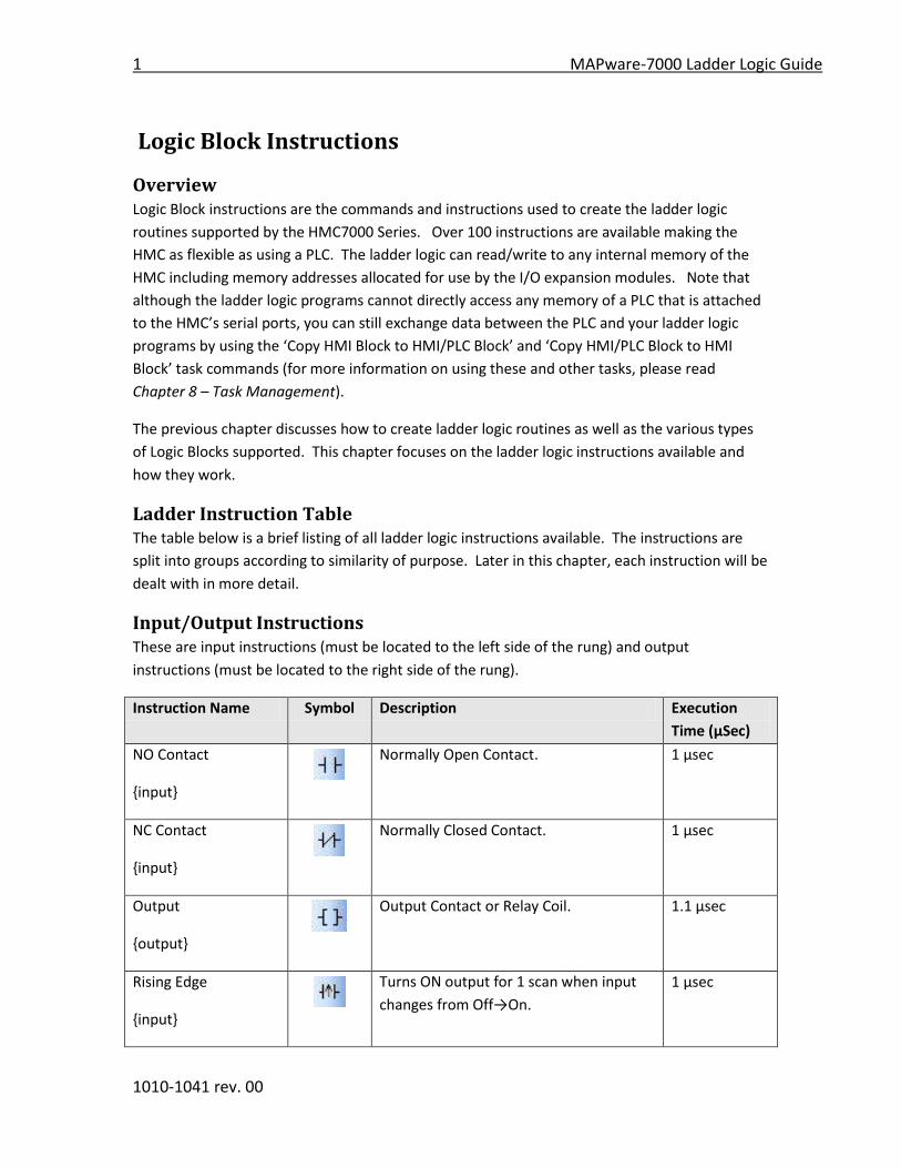
Input/Output Instructions These are input instructions (must be located to the left side of the rung) and output
instructions (must be located to the right side of the rung).
Instruction Name Symbol Description Execution
Time (μSec)
NO Contact
{input}
Normally Open Contact. 1 μsec
NC Contact
{input}
Normally Closed Contact. 1 μsec
Output
{output}
Output Contact or Relay Coil. 1.1 μsec
Rising Edge
{input}
Turns ON output for 1 scan when input
changes from Off→On.
1 μsec

MAPware-7000 Ladder Logic Guide 2
1010-1041 rev. 00
Instruction Name Symbol Description Execution
Time (μSec)
Falling Edge
{input}
Turns ON output for 1 scan when input
changes from On→Off.
1 μsec
Inverter
{input}
Inverts the input state. 0.8 μsec
Invert Coil
{output}
Stores the inverse state of the input
going into coil.
1.1 μsec
Positive Pulse Contact
{input}
Turns ON output for 1 scan when input is
ON and Operand A changes from
Off→On.
1.3 μsec
Negative Pulse
Contact
{input}
Turns ON output for 1 scan when input is
ON and Operand A changes from
On→Off.
1.3 μsec
Positive Pulse Coil
{output}
Turns ON Operand A for 1 scan when
input changes from Off→On.
1.3 μsec
Negative Pulse Coil
{output}
Turns ON Operand A for 1 scan when
input changes from On→Off.
1.3 μsec
Data Transfer Instructions These are instructions which can be used to move data from one (or more) memory location(s)
to another memory location(s).
Instruction Name Symbol Description Execution
Time (μSec)
MOV Word
Transfer data from one 16-bit register to
another.
1.9 μsec
MOV DWord
Transfer data from one 32-bit register to
another.
2.2 μsec
Invert Transfer
Transfers an inverted version of the data
in one register (ex. 1→0, and 0→1) to
1.9 μsec

3 MAPware-7000 Ladder Logic Guide
1010-1041 rev. 00
another.
Instruction Name Symbol Description Execution
Time (μSec)
Table Initialize
Transfers a constant value or a value in
the specified source register (Operand A)
to a series of consecutive registers (1 to
1024) beginning with the target register.
(Operand B)
1.8 μsec to
205.3 μsec
Table Block Transfer
Transfers a series of consecutive registers
(1 to 1024) beginning with the source
register (Operand A) to a series of
consecutive registers beginning with the
target register. (Operand B)
1.7 μsec to
271.4 μsec
Table Invert Transfer
Transfers a series of consecutive registers
(1 to 1024) beginning with the source
register (Operand A) to a series of
consecutive registers beginning with the
target register (Operand B). However,
the values transferred are inverted. (ex.
1→0, and 0→1).
1.6 μsec to
316.2 μsec
Data Exchange
The data values in the two specified
registers are exchanged or swapped.
2 μsec
Multiplexer
A particular register in a range of
registers (Operand A) is read and copied
to a target register (Operand C). Which
register read/copied is determined by the
value in Operand B register.
2.7 μsec
Demultiplexer
A register (Operand A) is read and copied
to a particular target register selected
from a range of registers (determined by
Operand C). Which target register
selected is determined by the value in
Operand B register.
2.5 μsec
MAPware-7000 Ladder Logic Guide 4
1010-1041 rev. 00
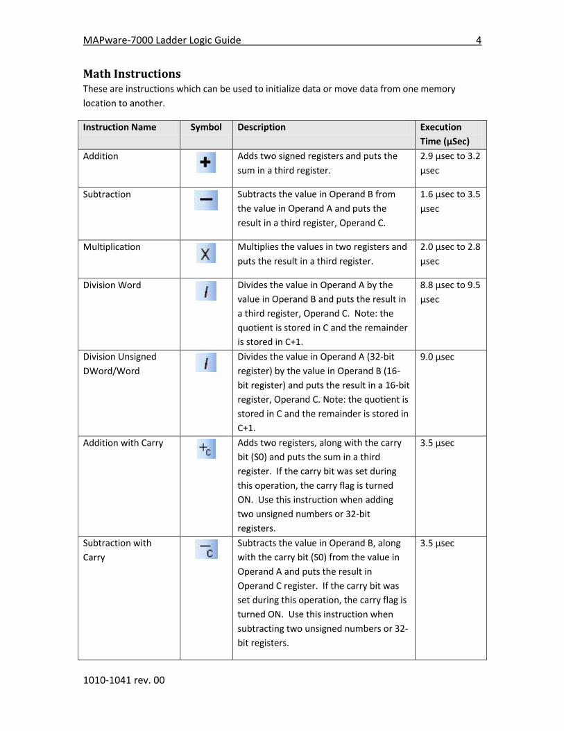
Math Instructions These are instructions which can be used to initialize data or move data from one memory
location to another.
Instruction Name Symbol Description Execution
Time (μSec)
Addition
Adds two signed registers and puts the
sum in a third register.
2.9 μsec to 3.2
μsec
Subtraction
Subtracts the value in Operand B from
the value in Operand A and puts the
result in a third register, Operand C.
1.6 μsec to 3.5
μsec
Multiplication
Multiplies the values in two registers and
puts the result in a third register.
2.0 μsec to 2.8
μsec
Division Word
Divides the value in Operand A by the
value in Operand B and puts the result in
a third register, Operand C. Note: the
quotient is stored in C and the remainder
is stored in C+1.
8.8 μsec to 9.5
μsec
Division Unsigned
DWord/Word Divides the value in Operand A (32-bit
register) by the value in Operand B (16-
bit register) and puts the result in a 16-bit
register, Operand C. Note: the quotient is
stored in C and the remainder is stored in
C+1.
9.0 μsec
Addition with Carry
Adds two registers, along with the carry
bit (S0) and puts the sum in a third
register. If the carry bit was set during
this operation, the carry flag is turned
ON. Use this instruction when adding
two unsigned numbers or 32-bit
registers.
3.5 μsec
Subtraction with
Carry
Subtracts the value in Operand B, along
with the carry bit (S0) from the value in
Operand A and puts the result in
Operand C register. If the carry bit was
set during this operation, the carry flag is
turned ON. Use this instruction when
subtracting two unsigned numbers or 32-
bit registers.
3.5 μsec
5 MAPware-7000 Ladder Logic Guide
1010-1041 rev. 00
Instruction Name Symbol Description Execution
Time (μSec)
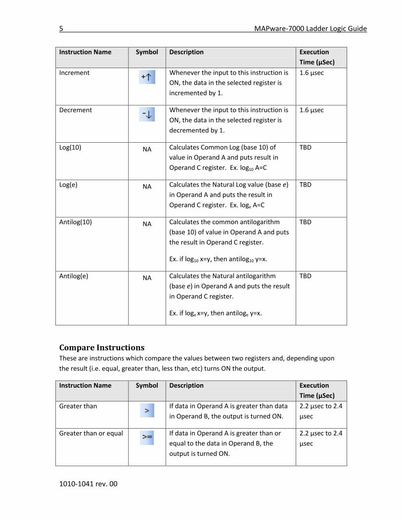
Increment
Whenever the input to this instruction is
ON, the data in the selected register is
incremented by 1.
1.6 μsec
Decrement
Whenever the input to this instruction is
ON, the data in the selected register is
decremented by 1.
1.6 μsec
Log(10) NA Calculates Common Log (base 10) of
value in Operand A and puts result in
Operand C register. Ex. log10 A=C
TBD
Log(e) NA Calculates the Natural Log value (base e)
in Operand A and puts the result in
Operand C register. Ex. loge A=C
TBD
Antilog(10) NA Calculates the common antilogarithm
(base 10) of value in Operand A and puts
the result in Operand C register.
Ex. if log10 x=y, then antilog10 y=x.
TBD
Antilog(e) NA Calculates the Natural antilogarithm
(base e) in Operand A and puts the result
in Operand C register.
Ex. if loge x=y, then antiloge y=x.
TBD
Compare Instructions These are instructions which compare the values between two registers and, depending upon
the result (i.e. equal, greater than, less than, etc) turns ON the output.
Instruction Name Symbol Description Execution
Time (μSec)
Greater than
If data in Operand A is greater than data
in Operand B, the output is turned ON.
2.2 μsec to 2.4
μsec
Greater than or equal
If data in Operand A is greater than or
equal to the data in Operand B, the
output is turned ON.
2.2 μsec to 2.4
μsec

MAPware-7000 Ladder Logic Guide 6
1010-1041 rev. 00
Instruction Name Symbol Description Execution
Time (μSec)
Equal
If data in Operand A is equal to the data
in Operand B, the output is turned ON.
2.3 μsec to 2.4
μsec
Not Equal
If data in Operand A is not equal to the
data in Operand B, the output is turned
ON.
2.2 μsec to 2.3
μsec
Less than
If data in Operand A is less than data in
Operand B, the output is turned ON.
2.1 μsec to 2.4
μsec
Less than or equal
If data in Operand A is less than or equal
to the data in Operand B, the output is
turned ON.
2.1 μsec to 2.4
μsec
Logic Instructions These are instructions which perform logic operations (i.e. AND, OR, XOR, etc.) on the selected
data registers.
Instruction Name Symbol Description Execution
Time (μSec)
AND
The data in Operand A is logic ANDed to
the data in Operand B and output to
Operand C.
2.7 μsec
OR
The data in Operand A is logic ORed to
the data in Operand B and output to
Operand C.
2.7 μsec
Exclusive OR
The data in Operand A is logic XORed to
the data in Operand B and output to
Operand C.
2.7 μsec
1 bit shift right
The data in the selected register is shifted
1 bit to the right (LSB direction). The least
significant bit is stored in the carry flag.
(S0)
2 μsec
1 bit shift left
The data in the selected register is shifted
1 bit to the left (MSB direction). The most
significant bit is stored in the carry flag.
(S0)
2 μsec
7 MAPware-7000 Ladder Logic Guide
1010-1041 rev. 00
Instruction Name Symbol Description Execution
Time (μSec)
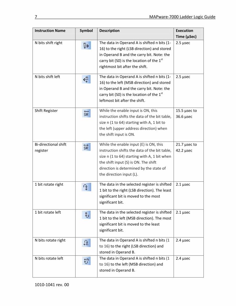
N bits shift right
The data in Operand A is shifted n bits (1-
16) to the right (LSB direction) and stored
in Operand B and the carry bit. Note: the
carry bit (S0) is the location of the 1st
rightmost bit after the shift.
2.5 μsec
N bits shift left
The data in Operand A is shifted n bits (1-
16) to the left (MSB direction) and stored
in Operand B and the carry bit. Note: the
carry bit (S0) is the location of the 1st
leftmost bit after the shift.
2.5 μsec
Shift Register
While the enable input is ON, this
instruction shifts the data of the bit table,
size n (1 to 64) starting with A, 1 bit to
the left (upper address direction) when
the shift input is ON.
15.5 μsec to
36.6 μsec
Bi-directional shift
register
While the enable input (E) is ON, this
instruction shifts the data of the bit table,
size n (1 to 64) starting with A, 1 bit when
the shift input (S) is ON. The shift
direction is determined by the state of
the direction input (L).
21.7 μsec to
42.2 μsec
1 bit rotate right
The data in the selected register is shifted
1 bit to the right (LSB direction). The least
significant bit is moved to the most
significant bit.
2.1 μsec
1 bit rotate left
The data in the selected register is shifted
1 bit to the left (MSB direction). The most
significant bit is moved to the least
significant bit.
2.1 μsec
N bits rotate right
The data in Operand A is shifted n bits (1
to 16) to the right (LSB direction) and
stored in Operand B.
2.4 μsec
N bits rotate left
The data in Operand A is shifted n bits (1
to 16) to the left (MSB direction) and
stored in Operand B.
2.4 μsec
MAPware-7000 Ladder Logic Guide 8
1010-1041 rev. 00
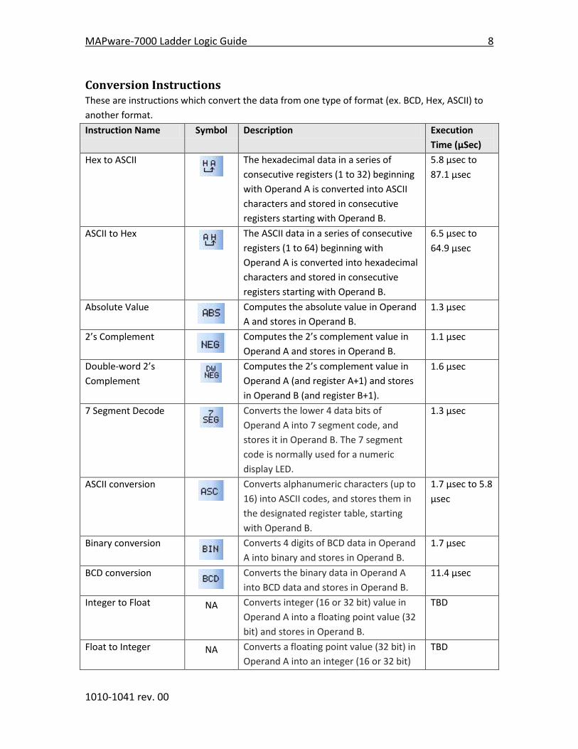
Conversion Instructions
These are instructions which convert the data from one type of format (ex. BCD, Hex, ASCII) to
another format.
Instruction Name Symbol Description Execution
Time (μSec)
Hex to ASCII
The hexadecimal data in a series of
consecutive registers (1 to 32) beginning
with Operand A is converted into ASCII
characters and stored in consecutive
registers starting with Operand B.
5.8 μsec to
87.1 μsec
ASCII to Hex
The ASCII data in a series of consecutive
registers (1 to 64) beginning with
Operand A is converted into hexadecimal
characters and stored in consecutive
registers starting with Operand B.
6.5 μsec to
64.9 μsec
Absolute Value
Computes the absolute value in Operand
A and stores in Operand B.
1.3 μsec
2’s Complement
Computes the 2’s complement value in
Operand A and stores in Operand B.
1.1 μsec
Double-word 2’s
Complement
Computes the 2’s complement value in
Operand A (and register A+1) and stores
in Operand B (and register B+1).
1.6 μsec
7 Segment Decode
Converts the lower 4 data bits of
Operand A into 7 segment code, and
stores it in Operand B. The 7 segment
code is normally used for a numeric
display LED.
1.3 μsec
ASCII conversion
Converts alphanumeric characters (up to
16) into ASCII codes, and stores them in
the designated register table, starting
with Operand B.
1.7 μsec to 5.8
μsec
Binary conversion
Converts 4 digits of BCD data in Operand
A into binary and stores in Operand B.
1.7 μsec
BCD conversion
Converts the binary data in Operand A
into BCD data and stores in Operand B.
11.4 μsec
Integer to Float NA Converts integer (16 or 32 bit) value in
Operand A into a floating point value (32
bit) and stores in Operand B.
TBD
Float to Integer NA Converts a floating point value (32 bit) in
Operand A into an integer (16 or 32 bit)
TBD

9 MAPware-7000 Ladder Logic Guide
1010-1041 rev. 00
value and stores in Operand B.
Timer Instructions These are instructions which run timers.
Instruction Name Symbol Description Execution
Time (μSec)
ON timer
While the input is ON, timer updates
according to the time specified
(hundredths of second) in Operand A.
Time elapsed is recorded in Operand B.
When time is reached, output is turned
ON and the update of Operand B stops.
When input is OFF, value in Operand B is
reset back to 0.
6.7 μsec
OFF timer
While the input is OFF, timer updates
according to the time specified
(hundredths of second) in Operand A.
Time elapsed is recorded in Operand B.
When time is reached, output is turned
OFF and the update of Operand B stops.
When input is ON, value in Operand B is
reset back to 0.
6.8 μsec
Single Shot timer
When the input is pulsed ON, timer
updates according to the time specified
(hundredths of second) in Operand A.
Time elapsed is recorded in Operand B.
Output is ON during this time until time is
reached, then Output is turned OFF and
remains OFF until input is pulsed again.
Value in Operand B is reset back to 0 if 1)
value equals preset value in Operand A
and then input is turned OFF or
2) input is turned OFF, value reaches
preset value, input is pulsed ON.
7.1 μsec
MAPware-7000 Ladder Logic Guide 10
1010-1041 rev. 00
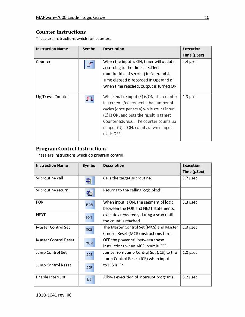
Counter Instructions These are instructions which run counters.
Instruction Name Symbol Description Execution
Time (μSec)
Counter
When the input is ON, timer will update
according to the time specified
(hundredths of second) in Operand A.
Time elapsed is recorded in Operand B.
When time reached, output is turned ON.
4.4 μsec
Up/Down Counter
While enable input (E) is ON, this counter
increments/decrements the number of
cycles (once per scan) while count input
(C) is ON, and puts the result in target
Counter address. The counter counts up
if input (U) is ON, counts down if input
(U) is OFF.
1.3 μsec
Program Control Instructions These are instructions which do program control.
Instruction Name Symbol Description Execution
Time (μSec)
Subroutine call
Calls the target subroutine. 2.7 μsec
Subroutine return
Returns to the calling logic block.
FOR
When input is ON, the segment of logic
between the FOR and NEXT statements.
3.3 μsec
NEXT
executes repeatedly during a scan until
the count is reached.
Master Control Set
The Master Control Set (MCS) and Master
Control Reset (MCR) instructions turn.
2.3 μsec
Master Control Reset
OFF the power rail between these
instructions when MCS input is OFF.
Jump Control Set
Jumps from Jump Control Set (JCS) to the
Jump Control Reset (JCR) when input
1.8 μsec
Jump Control Reset
to JCS is ON.
Enable Interrupt
Allows execution of interrupt programs. 5.2 μsec

11 MAPware-7000 Ladder Logic Guide
1010-1041 rev. 00
Instruction Name Symbol Description Execution
Time (μSec)
Disable Interrupt
Prevents execution of interrupt
programs.
Watchdog Timer
Reset
The built-in watchdog timer resets the
HMC7000 if timeout exceeds 200 msec.
This instruction extends that time by up
to an additional 100 msec.
1.0 μsec
Step Sequence
initialize
This function initializes a step sequencer.
It clears n bit registers starting with
Operand A, then sets Operand A.
3.5 μsec to
86.8 μsec
Step Sequence input
If input to this function is ON and
Operand A is ON, then turns the output
ON.
1.2 μsec
Step Sequence output
When input is ON, this functions resets all
bit registers of the step sequencer, then
sets Operand A.
1.9 μsec
Functions Instructions These are instructions which perform complex functions.
Instruction Name Symbol Description Execution
Time (μSec)
Moving Average
Calculates the average value of last n
scan values of A, and stores the result in
C.
5.7 to 45.5
μsec
Digital Filter
Filters the value of A by filter constant
specified by B, and stores the result in C.
28.4 μsec
PID 1,4
Performs PID control (pre-derivative real
PID algorithm):
Process value (PV): A
Set value (SV): A+1
PID parameters: B
Manipulation value (MV): C
35.9-44.7 μsec
MAPware-7000 Ladder Logic Guide 12
1010-1041 rev. 00
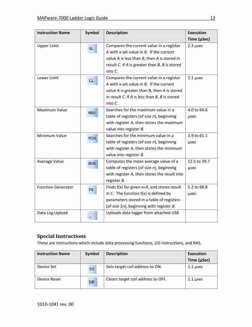
Instruction Name Symbol Description Execution
Time (μSec)
Upper Limit
Compares the current value in a register
A with a set value in B. If the current
value A is less than B, then A is stored in
result C. If A is greater than B, B is stored
into C.
2.3 μsec
Lower Limit
Compares the current value in a register
A with a set value in B. If the current
value A is greater than B, then A is stored
in result C. If A is less than B, B is stored
into C.
2.1 μsec
Maximum Value
Searches for the maximum value in a
table of registers (of size n), beginning
with register A, then stores the maximum
value into register B.
4.0 to 64.6
μsec
Minimum Value
Searches for the minimum value in a
table of registers (of size n), beginning
with register A, then stores the minimum
value into register B.
3.9 to 61.1
μsec
Average Value
Computes the mean average value of a
table of registers (of size n), beginning
with register A, then stores the result into
register B.
12.5 to 39.7
μsec
Function Generator
Finds f(x) for given x=A, and stores result
in C. The function f(x) is defined by
parameters stored in a table of registers
(of size 2n), beginning with register B.
5.2 to 68.8
μsec
Data Log Upload
Uploads data logger from attached USB
Special Instructions These are instructions which include data processing functions, I/O instructions, and RAS.
Instruction Name Symbol Description Execution
Time (μSec)
Device Set
Sets target coil address to ON. 1.1 μsec
Device Reset
Clears target coil address to OFF. 1.1 μsec
13 MAPware-7000 Ladder Logic Guide
1010-1041 rev. 00
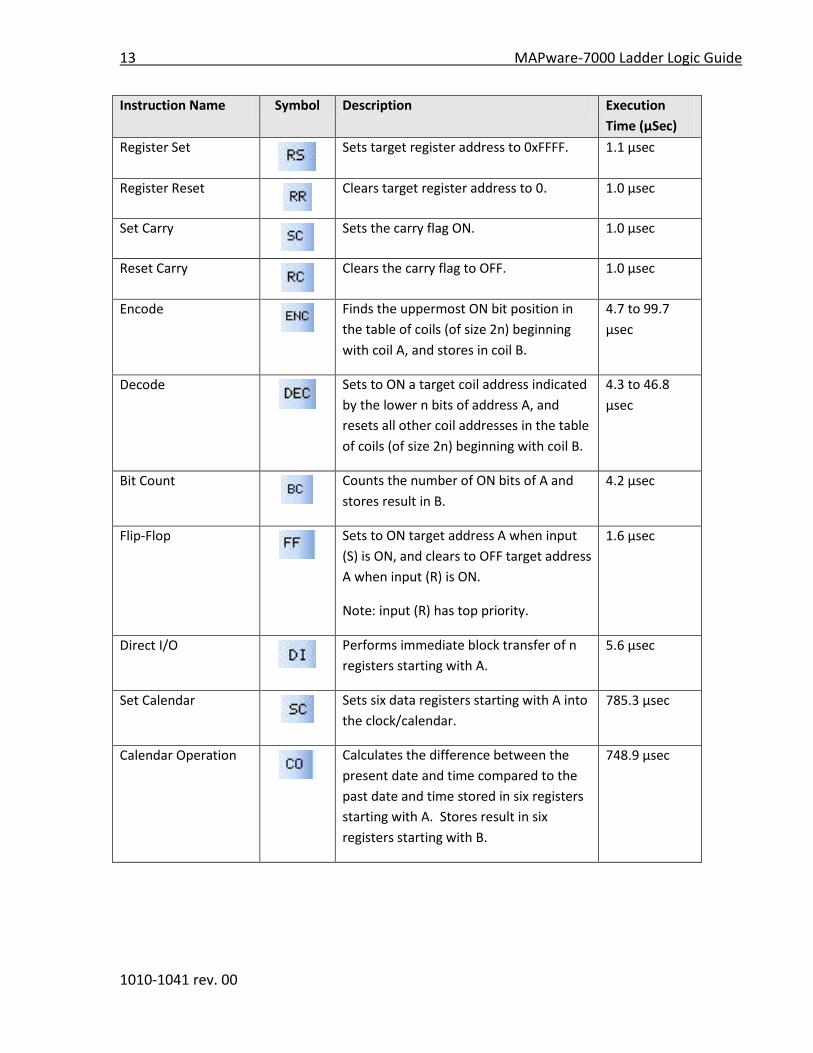
Instruction Name Symbol Description Execution
Time (μSec)
Register Set
Sets target register address to 0xFFFF. 1.1 μsec
Register Reset
Clears target register address to 0. 1.0 μsec
Set Carry
Sets the carry flag ON. 1.0 μsec
Reset Carry
Clears the carry flag to OFF. 1.0 μsec
Encode
Finds the uppermost ON bit position in
the table of coils (of size 2n) beginning
with coil A, and stores in coil B.
4.7 to 99.7
μsec
Decode
Sets to ON a target coil address indicated
by the lower n bits of address A, and
resets all other coil addresses in the table
of coils (of size 2n) beginning with coil B.
4.3 to 46.8
μsec
Bit Count
Counts the number of ON bits of A and
stores result in B.
4.2 μsec
Flip-Flop
Sets to ON target address A when input
(S) is ON, and clears to OFF target address
A when input (R) is ON.
Note: input (R) has top priority.
1.6 μsec
Direct I/O
Performs immediate block transfer of n
registers starting with A.
5.6 μsec
Set Calendar
Sets six data registers starting with A into
the clock/calendar.
785.3 μsec
Calendar Operation
Calculates the difference between the
present date and time compared to the
past date and time stored in six registers
starting with A. Stores result in six
registers starting with B.
748.9 μsec

MAPware-7000 Ladder Logic Guide 14
1010-1041 rev. 00
Instructions Defined
Instruction 1- NO Contact
Expression:
Space Requirement: 1 line x 1 column Location Requirement: Left rail, Middle
Function:
NO (normally open) contact of device A.
When the input is ON and the device A is ON, the output is turned ON.
Execution Condition:
Input Operation Output
OFF Regardless of the state of device A OFF
ON When device A is OFF. OFF
When device A is ON. ON
Operand:
Coil or Bit Register Constant Index
Name X Y B S T. C. M
X
W
Y
W
B
W
S
W T C D I J K
M
W
A Device √ √ √ √ √ √
Example:
Timing Diagram:
Coil Y0022 comes on when the devices X0000 and B0001 are both ON.

15 MAPware-7000 Ladder Logic Guide
1010-1041 rev. 00
Instruction 2- NC Contact
Expression:
Space Requirement: 1 line x 1 column Location Requirement: Left rail, Middle
Function:
NC (normally closed) contact of device A.
When the input is ON and the device A is OFF, the output is turned ON.
Execution Condition:
Input Operation Output
OFF Regardless of the state of device A OFF
ON When device A is OFF. ON
When device A is ON. OFF
Operand:
Coil or Bit Register Constant Index
Name X Y B S T. C. M
X
W
Y
W
B
W
S
W T C D I J K
M
W
A Device √ √ √ √ √ √
Example:
Timing Diagram:
Coil Y0022 comes on when the device X0000 and B0001 are both OFF.

MAPware-7000 Ladder Logic Guide 16
1010-1041 rev. 00
Instruction 3- Output
Expression:
Space Requirement: 1 line x 1 column Location Requirement: Right rail
Function:
This is the output coil of device A.
When the input is ON, the device A is ON.
Execution Condition:
Input Operation Output
OFF Sets device A to OFF. --
ON Sets device A to ON. --
Operand:
Coil or Bit Register Constant Index
Name X Y B S T. C. M
X
W
Y
W
B
W
S
W T C D I J K
M
W
A Device √ √ √
Example:
Timing Diagram:
Coil Y0005 comes on when the device X0000 is ON.

17 MAPware-7000 Ladder Logic Guide
1010-1041 rev. 00
Instruction 4- Rising Edge (Transitional Contact)
Expression:
Space Requirement: 1 line x 1 column Location Requirement: Left rail, Middle
Function:
When the input at last scan is OFF and the input at this scan is ON, the output is turned ON. This
instruction is used to detect the input changing from OFF to ON.
Execution Condition:
Input Operation Output
OFF Regardless of the input state at last scan. OFF
ON When the input state at last scan is OFF. ON
When the input state at last scan is ON. OFF
Operand:
No operand is required.
Example:
Timing Diagram:
Coil Y0002 comes ON for only 1 scan when the device X0000 comes ON.
MAPware-7000 Ladder Logic Guide 18
1010-1041 rev. 00
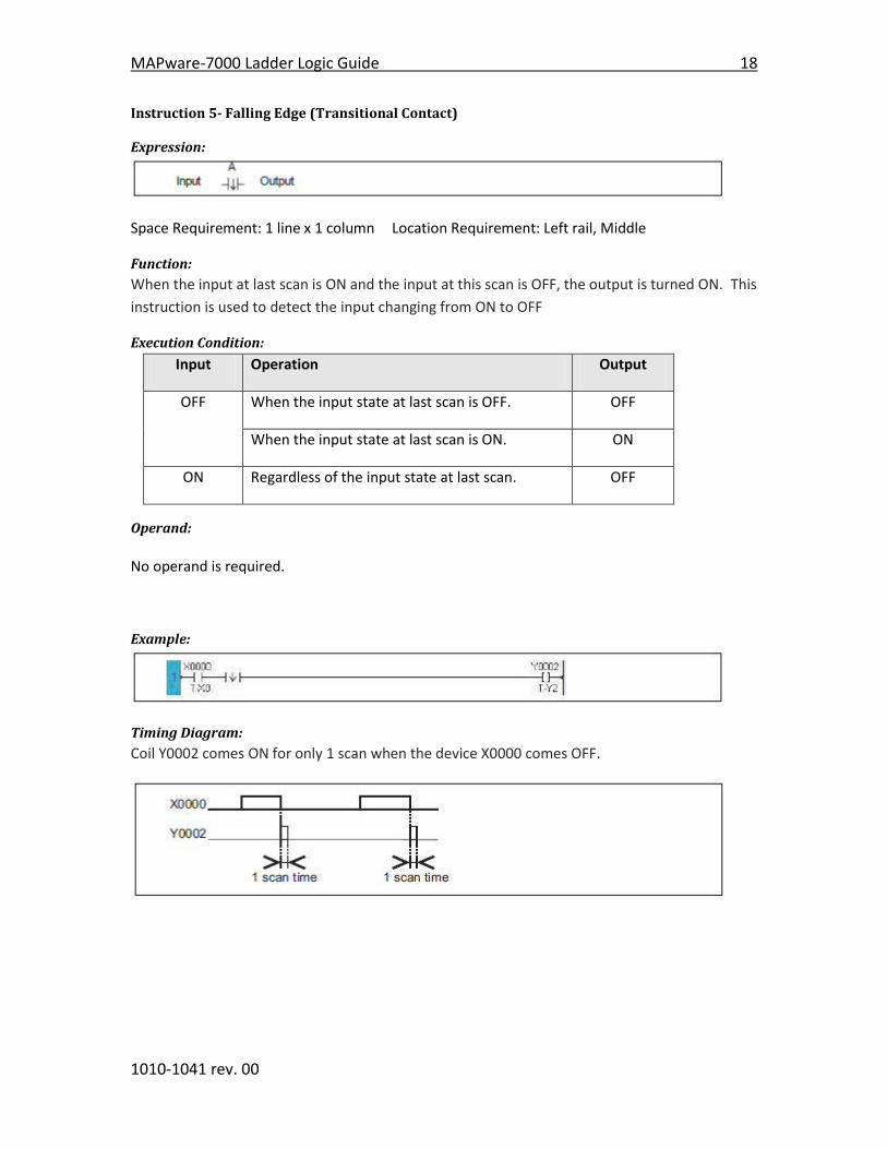
Instruction 5- Falling Edge (Transitional Contact)
Expression:
Space Requirement: 1 line x 1 column Location Requirement: Left rail, Middle
Function:
When the input at last scan is ON and the input at this scan is OFF, the output is turned ON. This
instruction is used to detect the input changing from ON to OFF
Execution Condition:
Input Operation Output
OFF When the input state at last scan is OFF. OFF
When the input state at last scan is ON. ON
ON Regardless of the input state at last scan. OFF
Operand:
No operand is required.
Example:
Timing Diagram:
Coil Y0002 comes ON for only 1 scan when the device X0000 comes OFF.
19 MAPware-7000 Ladder Logic Guide
1010-1041 rev. 00
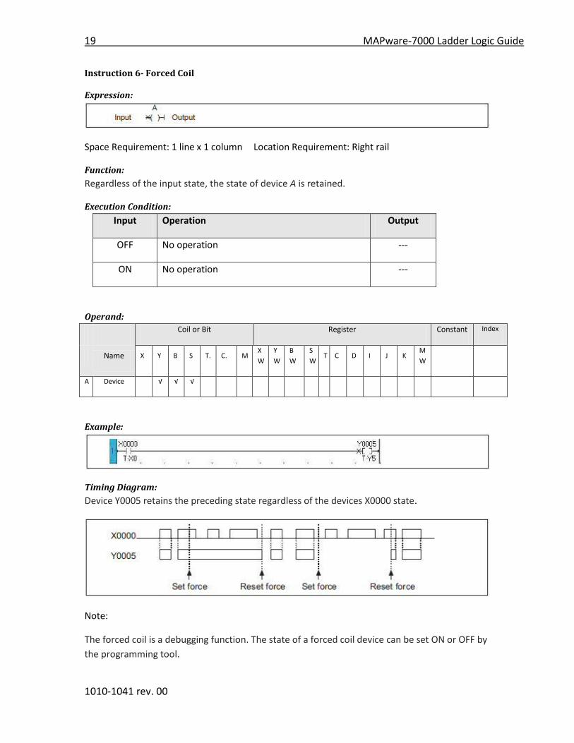
Instruction 6- Forced Coil
Expression:
Space Requirement: 1 line x 1 column Location Requirement: Right rail
Function:
Regardless of the input state, the state of device A is retained.
Execution Condition:
Input Operation Output
OFF No operation ---
ON No operation ---
Operand:
Coil or Bit Register Constant Index
Name X Y B S T. C. M
X
W
Y
W
B
W
S
W T C D I J K
M
W
A Device √ √ √
Example:
Timing Diagram:
Device Y0005 retains the preceding state regardless of the devices X0000 state.
Note:
The forced coil is a debugging function. The state of a forced coil device can be set ON or OFF by
the programming tool.

MAPware-7000 Ladder Logic Guide 20
1010-1041 rev. 00
Instruction 7- Inverter
Expression:
Space Requirement: 1 line x 1 column Location Requirement: Left rail, Middle
Function:
When the input is OFF, the output is turned ON, and when the input is ON, the output is turned
OFF. This instruction inverts the link state.
Execution Condition:
Input Operation Output
OFF Inverts the input state. ON
ON Inverts the input state. OFF
Operand:
No operand is required.
Example:
Timing Diagram:
Device Y0002 comes ON when X0000 is OFF, and Y0002 comes OFF when X0000 is ON.
21 MAPware-7000 Ladder Logic Guide
1010-1041 rev. 00
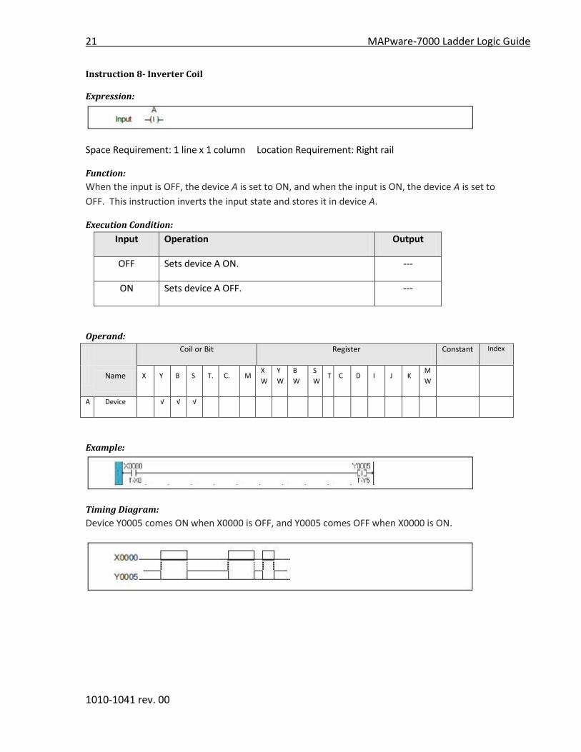
Instruction 8- Inverter Coil
Expression:
Space Requirement: 1 line x 1 column Location Requirement: Right rail
Function:
When the input is OFF, the device A is set to ON, and when the input is ON, the device A is set to
OFF. This instruction inverts the input state and stores it in device A.
Execution Condition:
Input Operation Output
OFF Sets device A ON. ---
ON Sets device A OFF. ---
Operand:
Coil or Bit Register Constant Index
Name X Y B S T. C. M
X
W
Y
W
B
W
S
W T C D I J K
M
W
A Device √ √ √
Example:
Timing Diagram:
Device Y0005 comes ON when X0000 is OFF, and Y0005 comes OFF when X0000 is ON.
MAPware-7000 Ladder Logic Guide 22
1010-1041 rev. 00
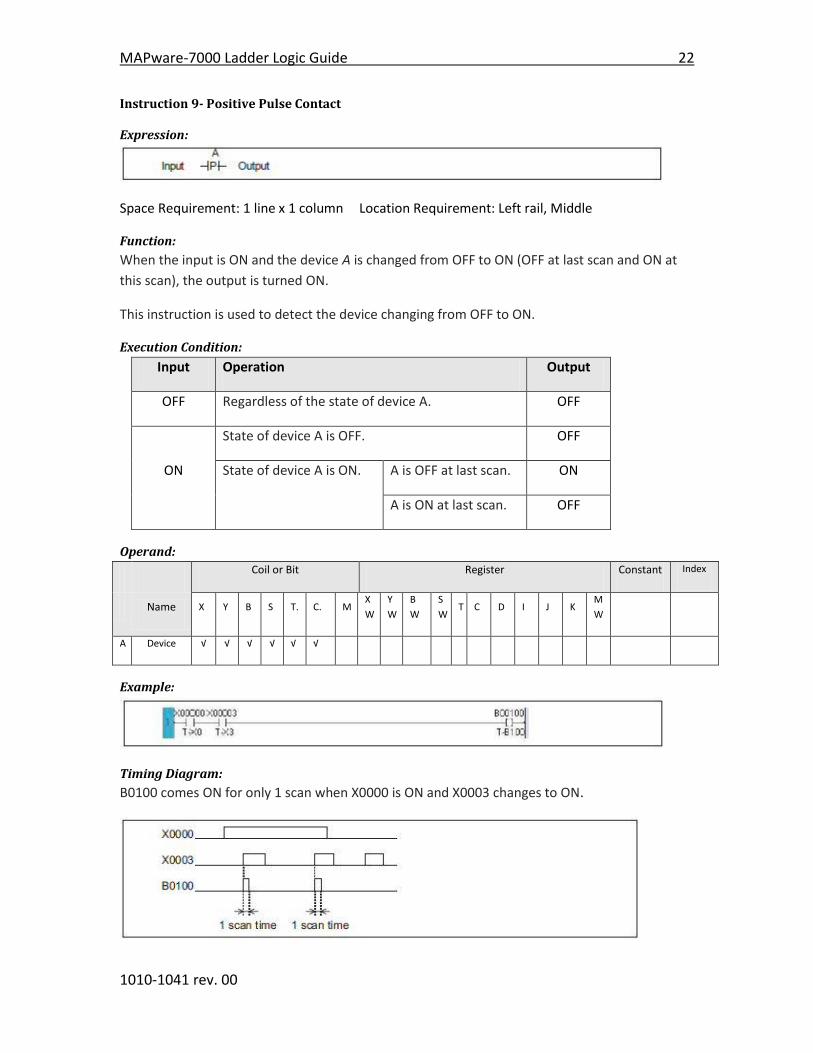
Instruction 9- Positive Pulse Contact
Expression:
Space Requirement: 1 line x 1 column Location Requirement: Left rail, Middle
Function:
When the input is ON and the device A is changed from OFF to ON (OFF at last scan and ON at
this scan), the output is turned ON.
This instruction is used to detect the device changing from OFF to ON.
Execution Condition:
Input Operation Output
OFF Regardless of the state of device A. OFF
State of device A is OFF. OFF
ON State of device A is ON. A is OFF at last scan. ON
A is ON at last scan. OFF
Operand:
Coil or Bit Register Constant Index
Name X Y B S T. C. M
X
W
Y
W
B
W
S
W T C D I J K
M
W
A Device √ √ √ √ √ √
Example:
Timing Diagram:
B0100 comes ON for only 1 scan when X0000 is ON and X0003 changes to ON.
23 MAPware-7000 Ladder Logic Guide
1010-1041 rev. 00
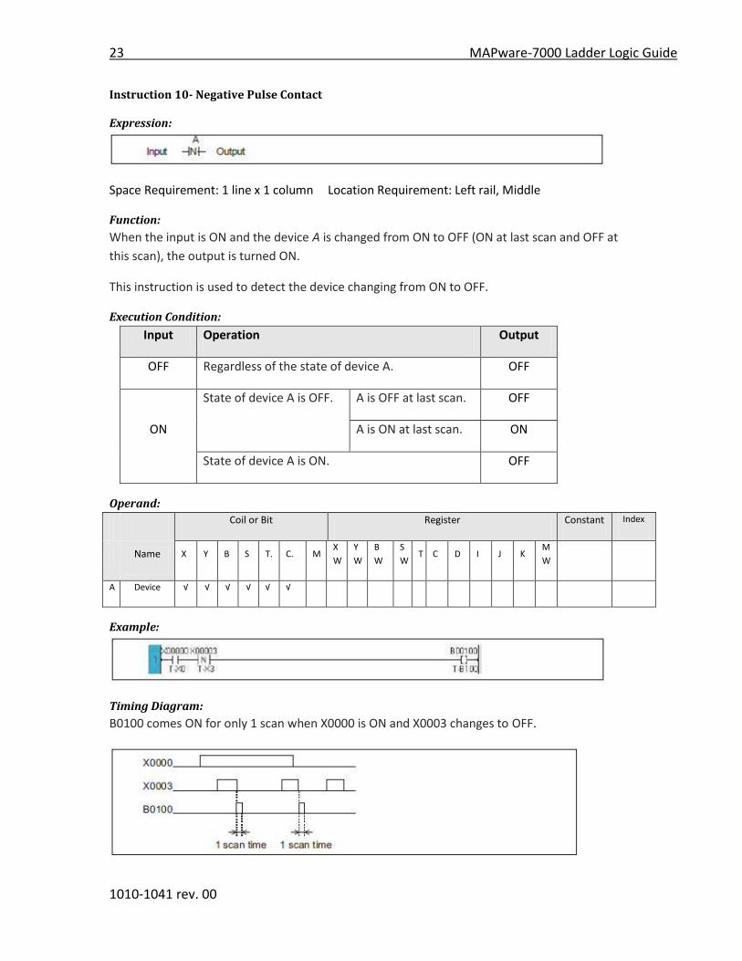
Instruction 10- Negative Pulse Contact
Expression:
Space Requirement: 1 line x 1 column Location Requirement: Left rail, Middle
Function:
When the input is ON and the device A is changed from ON to OFF (ON at last scan and OFF at
this scan), the output is turned ON.
This instruction is used to detect the device changing from ON to OFF.
Execution Condition:
Input Operation Output
OFF Regardless of the state of device A. OFF
State of device A is OFF. A is OFF at last scan. OFF
ON A is ON at last scan. ON
State of device A is ON. OFF
Operand:
Coil or Bit Register Constant Index
Name X Y B S T. C. M
X
W
Y
W
B
W
S
W T C D I J K
M
W
A Device √ √ √ √ √ √
Example:
Timing Diagram:
B0100 comes ON for only 1 scan when X0000 is ON and X0003 changes to OFF.

MAPware-7000 Ladder Logic Guide 24
1010-1041 rev. 00
Instruction 11- Positive Pulse Coil
Expression:
Space Requirement: 1 line x 1 column Location Requirement: Right rail
Function:
When the input is changed from OFF to ON, the device A is set to ON for 1 scan time.
This instruction is used to detect the input changing from OFF to ON.
Execution Condition:
Input Operation Output
OFF Sets device A to OFF. ---
ON When the input at last scan is OFF, sets A to ON. ---
When the input at last scan is OFF, sets A to OFF. ---
Operand:
Coil or Bit Register Constant Index
Name X Y B S T. C. M
X
W
Y
W
B
W
S
W T C D I J K
M
W
A Device √ √ √
Example:
Timing Diagram:
B0101 comes ON for only 1 scan when X0000 is changed from OFF to ON.
25 MAPware-7000 Ladder Logic Guide
1010-1041 rev. 00
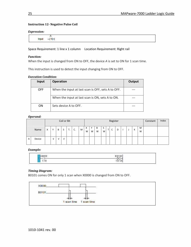
Instruction 12- Negative Pulse Coil
Expression:
Space Requirement: 1 line x 1 column Location Requirement: Right rail
Function:
When the input is changed from ON to OFF, the device A is set to ON for 1 scan time.
This instruction is used to detect the input changing from ON to OFF.
Execution Condition:
Input Operation Output
OFF When the input at last scan is OFF, sets A to OFF. ---
When the input at last scan is ON, sets A to ON. ---
ON Sets device A to OFF. ---
Operand:
Coil or Bit Register Constant Index
Name X Y B S T. C. M
X
W
Y
W
B
W
S
W T C D I J K
M
W
A Device √ √ √
Example:
Timing Diagram:
B0101 comes ON for only 1 scan when X0000 is changed from ON to OFF.

MAPware-7000 Ladder Logic Guide 26
1010-1041 rev. 00
Instruction 13- MOV Word
Expression:
Space Requirement: 1 line x 5 column Location Requirement: Middle, Right rail
Function:
When the input is ON, the data of A is stored in B.
Execution Condition:
Input Operation Output
OFF No execution OFF
ON Execution ON
Operand:
Coil or Bit Register Constant Index
Name X Y B S T. C. M
X
W
Y
W
B
W
S
W T C D I J K
M
W
A Source √ √ √ √ √ √ √ √ √ √ √ √
B Destination √ √ √ √ √ √ √ √ √ √
Examples:
Sample 1- Moving a constant value into a register
B0010 is ON, a constant data (12345) is stored in D0100 and the output is turned ON.
Sample 2- Copying a value in a register to another register
When B00010 is ON, the data of SW030 is stored in BW045 and the output is turned ON. If
SW030 is 500, the data 500 is stored in BW045.
27 MAPware-7000 Ladder Logic Guide
1010-1041 rev. 00
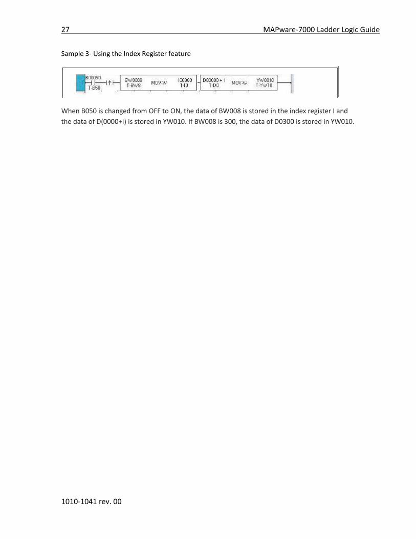
Sample 3- Using the Index Register feature
When B050 is changed from OFF to ON, the data of BW008 is stored in the index register I and
the data of D(0000+I) is stored in YW010. If BW008 is 300, the data of D0300 is stored in YW010.

MAPware-7000 Ladder Logic Guide 28
1010-1041 rev. 00
Instruction 14- MOV DWord
Expression:
Space Requirement: 1 line x 5 column Location Requirement: Middle, Right rail
Function:
When the input is ON, the double-word (32-bit) data of A+1× A is stored in double-word register
B+1× B. The data range is -2147483648 to 2147483647.
Execution Condition:
Input Operation Output
OFF No execution OFF
ON Execution ON
Operand:
Coil or Bit Register Constant Index
Name X Y B S T. C. M
X
W
Y
W
B
W
S
W T C D I J K
M
W
A Source √ √ √ √ √ √ √ √ √ √ √ √
B Destination √ √ √ √ √ √ √ √ √ √
Example:
When B011 is ON, a double-word data of D0101×D0100 is stored in BW17×BW16 and the
output is turned ON. If D0101×D0100 is 1234567, the data 1234567 is stored in BW17×BW16.
29 MAPware-7000 Ladder Logic Guide
1010-1041 rev. 00
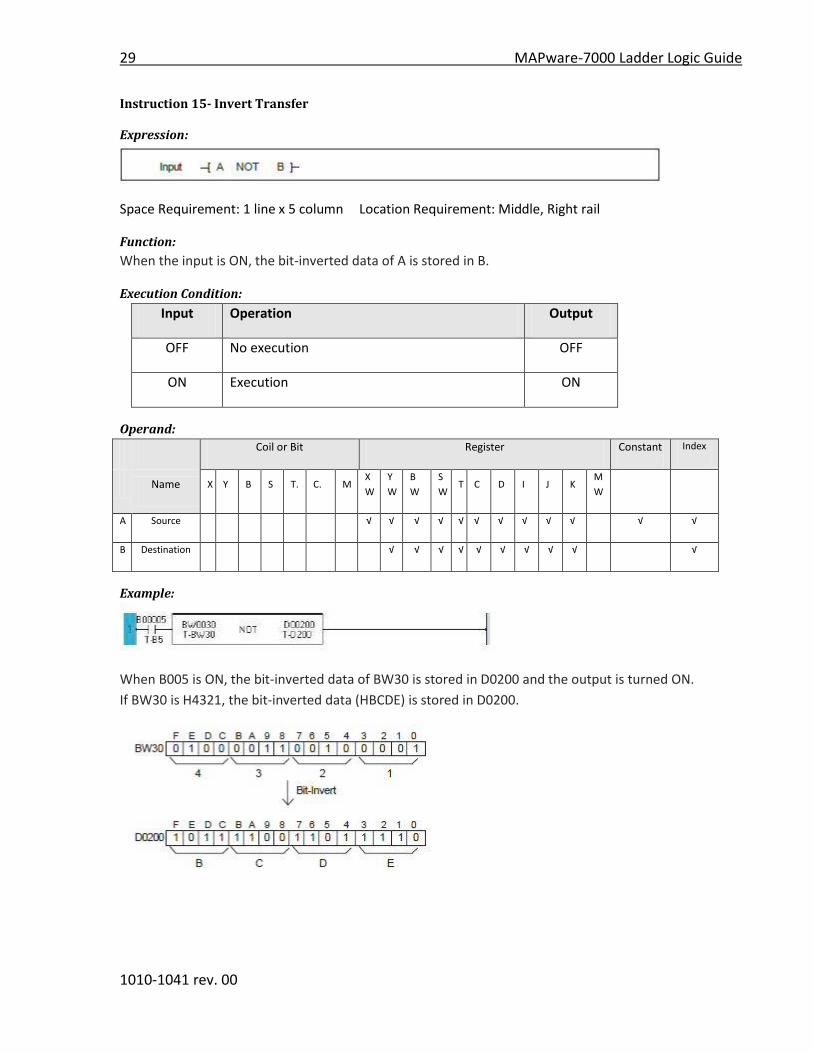
Instruction 15- Invert Transfer
Expression:
Space Requirement: 1 line x 5 column Location Requirement: Middle, Right rail
Function:
When the input is ON, the bit-inverted data of A is stored in B.
Execution Condition:
Input Operation Output
OFF No execution OFF
ON Execution ON
Operand:
Coil or Bit Register Constant Index
Name X Y B S T. C. M
X
W
Y
W
B
W
S
W T C D I J K
M
W
A Source √ √ √ √ √ √ √ √ √ √ √ √
B Destination √ √ √ √ √ √ √ √ √ √
Example:
When B005 is ON, the bit-inverted data of BW30 is stored in D0200 and the output is turned ON.
If BW30 is H4321, the bit-inverted data (HBCDE) is stored in D0200.
MAPware-7000 Ladder Logic Guide 30
1010-1041 rev. 00
Instruction 16- Table Initialize
Expression:
Space Requirement: 1 line x 5 column Location Requirement: Middle, Right rail
Function:
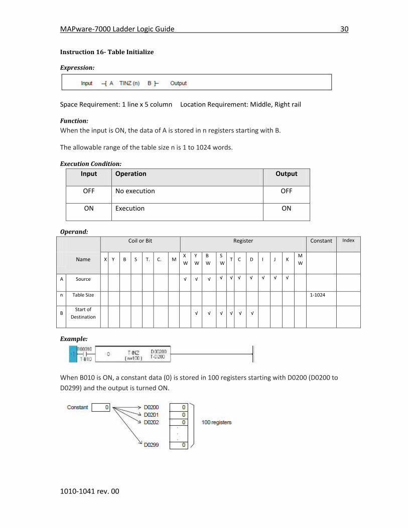
When the input is ON, the data of A is stored in n registers starting with B.
The allowable range of the table size n is 1 to 1024 words.
Execution Condition:
Input Operation Output
OFF No execution OFF
ON Execution ON
Operand:
Coil or Bit Register Constant Index
Name X Y B S T. C. M
X
W
Y
W
B
W
S
W T C D I J K
M
W
A Source √ √ √ √ √ √ √ √ √ √
n Table Size 1-1024
B Start of
Destination √ √ √ √ √ √
Example:
When B010 is ON, a constant data (0) is stored in 100 registers starting with D0200 (D0200 to
D0299) and the output is turned ON.
31 MAPware-7000 Ladder Logic Guide
1010-1041 rev. 00
Instruction 17- Table Block Transfer
Expression:
Space Requirement: 1 line x 5 column Location Requirement: Middle, Right rail
Function:
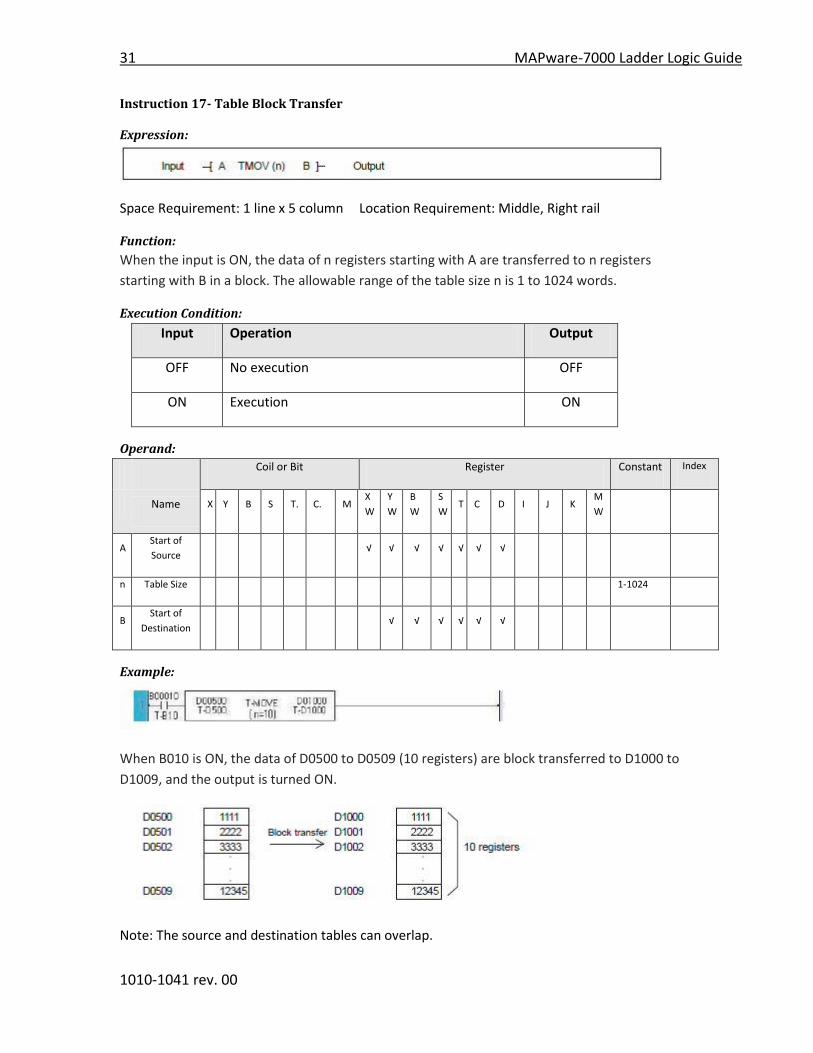
When the input is ON, the data of n registers starting with A are transferred to n registers
starting with B in a block. The allowable range of the table size n is 1 to 1024 words.
Execution Condition:
Input Operation Output
OFF No execution OFF
ON Execution ON
Operand:
Coil or Bit Register Constant Index
Name X Y B S T. C. M
X
W
Y
W
B
W
S
W T C D I J K
M
W
A Start of
Source √ √ √ √ √ √ √
n Table Size 1-1024
B Start of
Destination √ √ √ √ √ √
Example:
When B010 is ON, the data of D0500 to D0509 (10 registers) are block transferred to D1000 to
D1009, and the output is turned ON.
Note: The source and destination tables can overlap.
MAPware-7000 Ladder Logic Guide 32
1010-1041 rev. 00
Instruction 18- Table Invert Transfer
Expression:
Space Requirement: 1 line x 5 column Location Requirement: Middle, Right rail
Function:
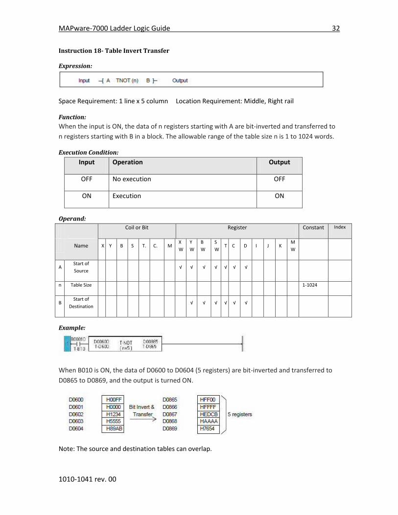
When the input is ON, the data of n registers starting with A are bit-inverted and transferred to
n registers starting with B in a block. The allowable range of the table size n is 1 to 1024 words.
Execution Condition:
Input Operation Output
OFF No execution OFF
ON Execution ON
Operand:
Coil or Bit Register Constant Index
Name X Y B S T. C. M
X
W
Y
W
B
W
S
W T C D I J K
M
W
A Start of
Source √ √ √ √ √ √ √
n Table Size 1-1024
B Start of
Destination √ √ √ √ √ √
Example:
When B010 is ON, the data of D0600 to D0604 (5 registers) are bit-inverted and transferred to
D0865 to D0869, and the output is turned ON.
Note: The source and destination tables can overlap.

33 MAPware-7000 Ladder Logic Guide
1010-1041 rev. 00
Instruction 19- Data Exchange
Expression:
Space Requirement: 1 line x 5 column Location Requirement: Middle, Right rail
Function:
When the input is ON, the data of A and the data of B is exchanged.
Execution Condition:
Input Operation Output
OFF No execution OFF
ON Execution ON
Operand:
Coil or Bit Register Constant Index
Name X Y B S T. C. M
X
W
Y
W
B
W
S
W T C D I J K
M
W
A Operation
Data √ √ √ √ √ √ √ √ √ √
B Operation
Data √ √ √ √ √ √ √ √ √
√
Example:
When B005 is ON, the data of BW23 and D0100 is exchanged. If the original data of BW23 is
23456 and that of D0100 is 291, the operation result is as follows.
Before Operation After Operation
MAPware-7000 Ladder Logic Guide 34
1010-1041 rev. 00
Instruction 20- Multiplexer
Expression:
Space Requirement: 1 line x 6 column Location Requirement: Middle, Right rail
Function:
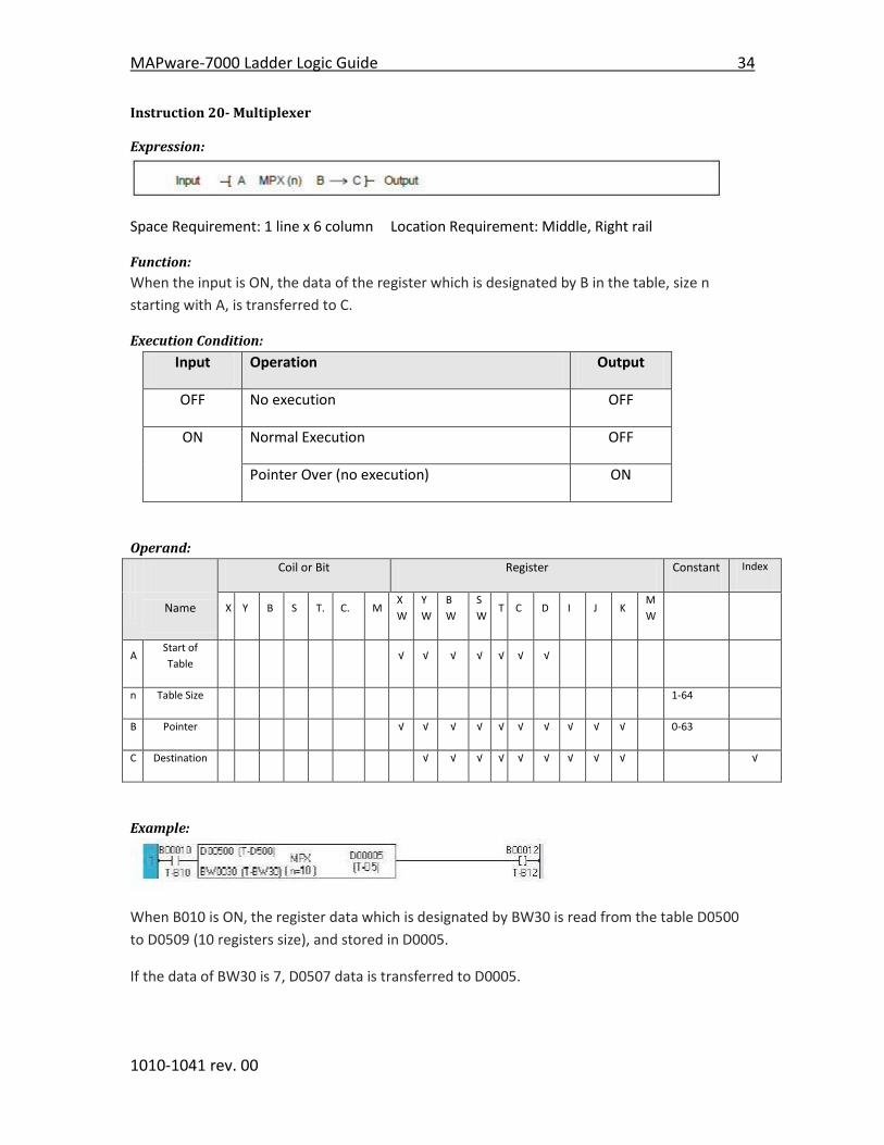
When the input is ON, the data of the register which is designated by B in the table, size n
starting with A, is transferred to C.
Execution Condition:
Input Operation Output
OFF No execution OFF
ON Normal Execution OFF
Pointer Over (no execution) ON
Operand:
Coil or Bit Register Constant Index
Name X Y B S T. C. M
X
W
Y
W
B
W
S
W T C D I J K
M
W
A Start of
Table √ √ √ √ √ √ √
n Table Size 1-64
B Pointer √ √ √ √ √ √ √ √ √ √ 0-63
C Destination √ √ √ √ √ √ √ √ √ √
Example:
When B010 is ON, the register data which is designated by BW30 is read from the table D0500
to D0509 (10 registers size), and stored in D0005.
If the data of BW30 is 7, D0507 data is transferred to D0005.

35 MAPware-7000 Ladder Logic Guide
1010-1041 rev. 00
Note: If the pointer data designates outside the table (10 or more in the above example), the
transfer is not executed and the output comes ON.
The table must be within the effective range of the register address.

MAPware-7000 Ladder Logic Guide 36
1010-1041 rev. 00
Instruction 21- Demultiplexer
Expression:
Space Requirement: 1 line x 6 column Location Requirement: Middle, Right rail
Function:
When the input is ON, the data of A is transferred to the register which is designated by B in the
table, size n starting with C.
Execution Condition:
Input Operation Output
OFF No execution OFF
ON Normal Execution OFF
Pointer Over (no execution) ON
Operand:
Coil or Bit Register Constant Index
Name X Y B S T. C. M
X
W
Y
W
B
W
S
W T C D I J K
M
W
A Source √ √ √ √ √ √ √ √ √ √ √
n Table Size 1-64
B Pointer √ √ √ √ √ √ √ √ √ √ 0-63
C Start of
Table √ √ √ √ √ √
Example:
When B011 is ON, the data of XW04 is transferred to the register which is designated by BW30
in the table D0500 to D0509 (10 registers size).
If the data of BW30 is 8, XW04 data is transferred to D0508.

37 MAPware-7000 Ladder Logic Guide
1010-1041 rev. 00
Note: If the pointer data designates outside the table (10 or more in the above example), the
transfer is not executed and the output comes ON.
The table must be within the effective range of the register address.
MAPware-7000 Ladder Logic Guide 38
1010-1041 rev. 00
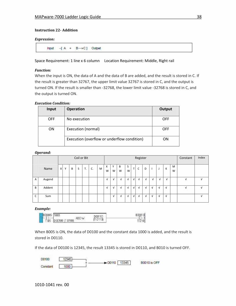
Instruction 22- Addition
Expression:
Space Requirement: 1 line x 6 column Location Requirement: Middle, Right rail
Function:
When the input is ON, the data of A and the data of B are added, and the result is stored in C. If
the result is greater than 32767, the upper limit value 32767 is stored in C, and the output is
turned ON. If the result is smaller than -32768, the lower limit value -32768 is stored in C, and
the output is turned ON.
Execution Condition:
Input Operation Output
OFF No execution OFF
ON Execution (normal) OFF
Execution (overflow or underflow condition) ON
Operand:
Coil or Bit Register Constant Index
Name X Y B S T. C. M
X
W
Y
W
B
W
S
W T C D I J K
M
W
A Augend √ √ √ √ √ √ √ √ √ √ √ √
B Addent √ √ √ √ √ √ √ √ √ √ √ √
C Sum √ √ √ √ √ √ √ √ √ √
Example:
When B005 is ON, the data of D0100 and the constant data 1000 is added, and the result is
stored in D0110.
If the data of D0100 is 12345, the result 13345 is stored in D0110, and B010 is turned OFF.
39 MAPware-7000 Ladder Logic Guide
1010-1041 rev. 00
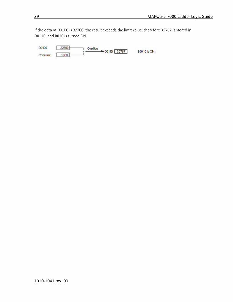
If the data of D0100 is 32700, the result exceeds the limit value, therefore 32767 is stored in
D0110, and B010 is turned ON.

MAPware-7000 Ladder Logic Guide 40
1010-1041 rev. 00
Instruction 23- Double-Word Addition
Select the “Addition” function and place it in the logic block.
Select “DWord” from the Data Properties selection tab as shown below:
Thus by selecting “DWord” in Data Properties, the Addition function can be changed to “Double-
word Addition” entry as shown below:
Expression:
Space Requirement: 1 line x 6 column Location Requirement: Middle, Right rail
Function:
When the input is ON, the double-word data of A+1× A and B+1× B are added, and the result is
stored in C+1× C. The data range is -2147483648 to 2147483647.
41 MAPware-7000 Ladder Logic Guide
1010-1041 rev. 00
If the result is greater than 2147483647, the upper limit value 2147483647 is stored in C+1× C,
and the output is turned ON. If the result is smaller than -2147483648, the lower limit value -
2147483648 is stored in C+1× C, and the output is turned ON.
Execution Condition:
Input Operation Output
OFF No execution OFF
ON Execution (normal) OFF
Execution (overflow or underflow condition) ON
Operand:
Coil or Bit Register Constant Index
Name X Y B S T. C. M
X
W
Y
W
B
W
S
W T C D I J K
M
W
A Augend √ √ √ √ √ √ √ √
B Addent √ √ √ √ √ √ √ √
C Sum √ √ √ √ √ √
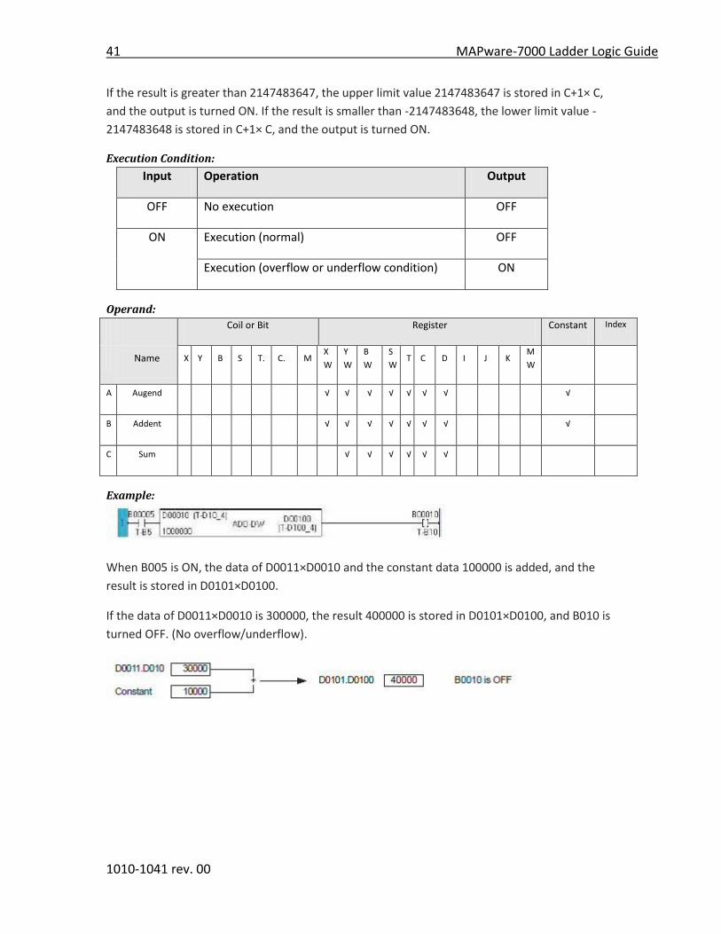
Example:
When B005 is ON, the data of D0011×D0010 and the constant data 100000 is added, and the
result is stored in D0101×D0100.
If the data of D0011×D0010 is 300000, the result 400000 is stored in D0101×D0100, and B010 is
turned OFF. (No overflow/underflow).
MAPware-7000 Ladder Logic Guide 42
1010-1041 rev. 00
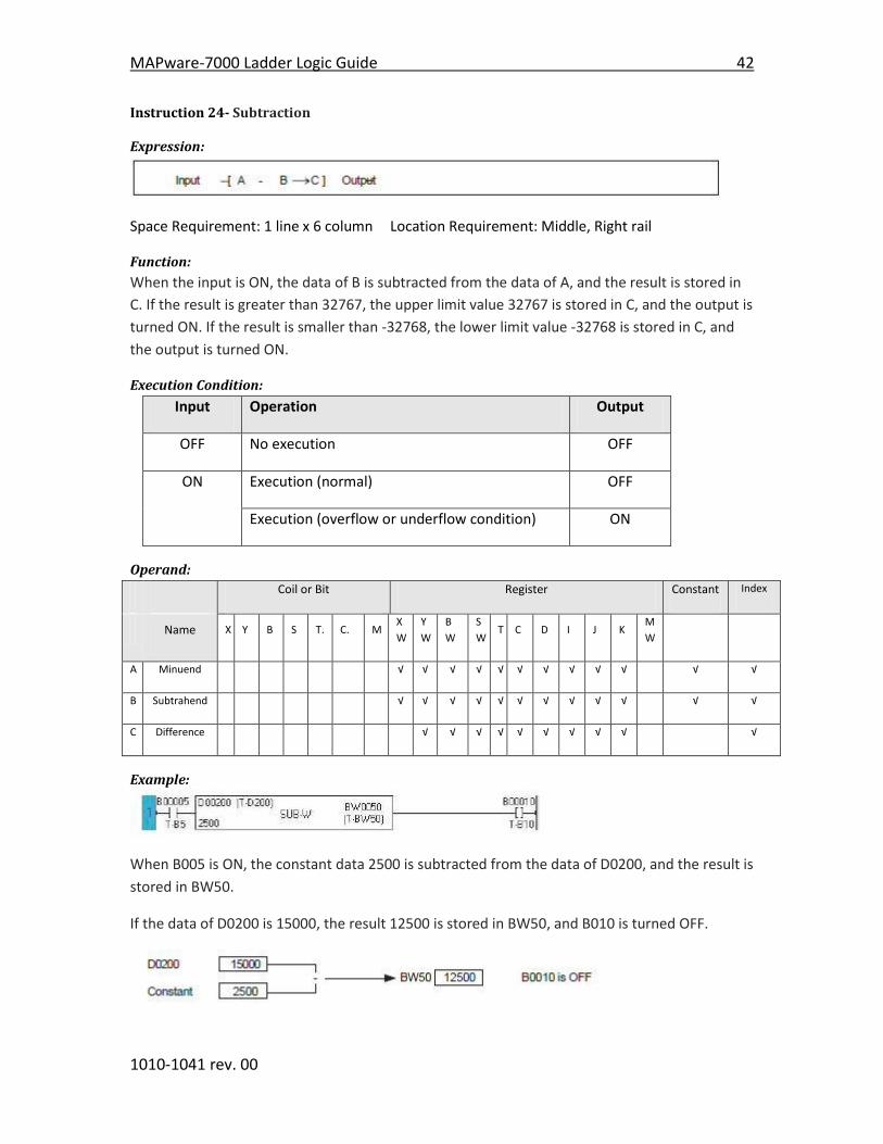
Instruction 24- Subtraction
Expression:
Space Requirement: 1 line x 6 column Location Requirement: Middle, Right rail
Function:
When the input is ON, the data of B is subtracted from the data of A, and the result is stored in
C. If the result is greater than 32767, the upper limit value 32767 is stored in C, and the output is
turned ON. If the result is smaller than -32768, the lower limit value -32768 is stored in C, and
the output is turned ON.
Execution Condition:
Input Operation Output
OFF No execution OFF
ON Execution (normal) OFF
Execution (overflow or underflow condition) ON
Operand:
Coil or Bit Register Constant Index
Name X Y B S T. C. M
X
W
Y
W
B
W
S
W T C D I J K
M
W
A Minuend √ √ √ √ √ √ √ √ √ √ √ √
B Subtrahend √ √ √ √ √ √ √ √ √ √ √ √
C Difference √ √ √ √ √ √ √ √ √ √
Example:
When B005 is ON, the constant data 2500 is subtracted from the data of D0200, and the result is
stored in BW50.
If the data of D0200 is 15000, the result 12500 is stored in BW50, and B010 is turned OFF.

43 MAPware-7000 Ladder Logic Guide
1010-1041 rev. 00
If the data of D0200 is -31000, the result is smaller than the limit value, therefore -32768 is
stored in BW50, and B010 is turned ON.
MAPware-7000 Ladder Logic Guide 44
1010-1041 rev. 00
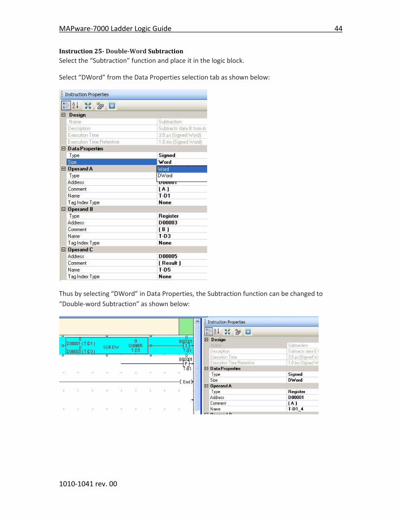
Instruction 25- Double-Word Subtraction
Select the “Subtraction” function and place it in the logic block.
Select “DWord” from the Data Properties selection tab as shown below:
Thus by selecting “DWord” in Data Properties, the Subtraction function can be changed to
“Double-word Subtraction” as shown below:
45 MAPware-7000 Ladder Logic Guide
1010-1041 rev. 00
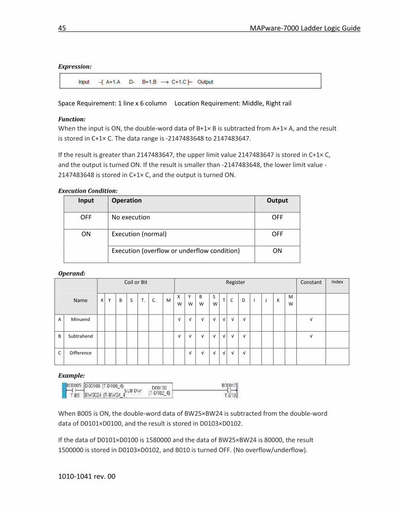
Expression:
Space Requirement: 1 line x 6 column Location Requirement: Middle, Right rail
Function:
When the input is ON, the double-word data of B+1× B is subtracted from A+1× A, and the result
is stored in C+1× C. The data range is -2147483648 to 2147483647.
If the result is greater than 2147483647, the upper limit value 2147483647 is stored in C+1× C,
and the output is turned ON. If the result is smaller than -2147483648, the lower limit value -
2147483648 is stored in C+1× C, and the output is turned ON.
Execution Condition:
Input Operation Output
OFF No execution OFF
ON Execution (normal) OFF
Execution (overflow or underflow condition) ON
Operand:
Coil or Bit Register Constant Index
Name X Y B S T. C. M
X
W
Y
W
B
W
S
W T C D I J K
M
W
A Minuend √ √ √ √ √ √ √ √
B Subtrahend √ √ √ √ √ √ √ √
C Difference √ √ √ √ √ √
Example:
When B005 is ON, the double-word data of BW25×BW24 is subtracted from the double-word
data of D0101×D0100, and the result is stored in D0103×D0102.
If the data of D0101×D0100 is 1580000 and the data of BW25×BW24 is 80000, the result
1500000 is stored in D0103×D0102, and B010 is turned OFF. (No overflow/underflow).

MAPware-7000 Ladder Logic Guide 46
1010-1041 rev. 00
47 MAPware-7000 Ladder Logic Guide
1010-1041 rev. 00
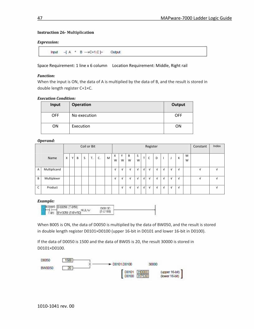
Instruction 26- Multiplication
Expression:
Space Requirement: 1 line x 6 column Location Requirement: Middle, Right rail
Function:
When the input is ON, the data of A is multiplied by the data of B, and the result is stored in
double length register C+1×C.
Execution Condition:
Input Operation Output
OFF No execution OFF
ON Execution ON
Operand:
Coil or Bit Register Constant Index
Name X Y B S T. C. M
X
W
Y
W
B
W
S
W T C D I J K
M
W
A Multiplicand √ √ √ √ √ √ √ √ √ √ √ √
B Multiplexer √ √ √ √ √ √ √ √ √ √ √ √
C Product √ √ √ √ √ √ √ √ √ √
Example:
When B005 is ON, the data of D0050 is multiplied by the data of BW050, and the result is stored
in double length register D0101×D0100 (upper 16-bit in D0101 and lower 16-bit in D0100).
If the data of D0050 is 1500 and the data of BW05 is 20, the result 30000 is stored in
D0101×D0100.

MAPware-7000 Ladder Logic Guide 48
1010-1041 rev. 00
Instruction 27- Unsigned Multiplication
Select “Multiplication” function and place it in the logic block.
Select “Unsigned” in the Data Properties selection tab as shown below:
49 MAPware-7000 Ladder Logic Guide
1010-1041 rev. 00
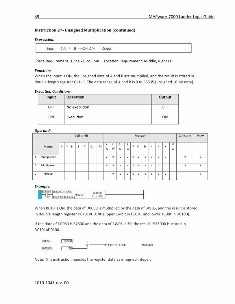
Instruction 27- Unsigned Multiplication (continued)
Expression:
Space Requirement: 1 line x 6 column Location Requirement: Middle, Right rail
Function:
When the input is ON, the unsigned data of A and B are multiplied, and the result is stored in
double-length register C+1×C. The data range of A and B is 0 to 65535 (unsigned 16-bit data).
Execution Condition:
Input Operation Output
OFF No execution OFF
ON Execution ON
Operand:
Coil or Bit Register Constant Index
Name X Y B S T. C. M
X
W
Y
W
B
W
S
W T C D I J K
M
W
A Multiplicand √ √ √ √ √ √ √ √ √ √ √ √
B Multiplexer √ √ √ √ √ √ √ √ √ √ √ √
C Product √ √ √ √ √ √ √ √ √ √
Example:
When B010 is ON, the data of D0050 is multiplied by the data of BW05, and the result is stored
in double length register D0101×D0100 (upper 16-bit in D0101 and lower 16-bit in D0100).
If the data of D0050 is 52500 and the data of BW05 is 30, the result 1575000 is stored in
D0101×D0100.
Note: This instruction handles the register data as unsigned integer.

MAPware-7000 Ladder Logic Guide 50
1010-1041 rev. 00
Instruction 28- Division
Expression:
Space Requirement: 1 line x 6 column Location Requirement: Middle, Right rail
Function:
When the input is ON, the data of A is divided by the data of B, and the quotient is stored in C
and the remainder in C+1.
Execution Condition:
Input Operation Output ERF
OFF No execution OFF ---
ON Normal Execution (B ≠ 0) ON ---
No execution ( B = 0) OFF ---
Operand:
Coil or Bit Register Constant Index
Name X Y B S T. C. M
X
W
Y
W
B
W
S
W T C D I J K
M
W
A Multiplicand √ √ √ √ √ √ √ √ √ √ √ √
B Multiplexer √ √ √ √ √ √ √ √ √ √ √ √
C Product √ √ √ √ √ √ √ √ √ √
Example:
When B005 is ON, the data of BW22 is divided by the constant data 325, and the quotient is
stored in BW27 and the remainder is stored in BW28.
If the data of BW22 is 2894, the quotient 8 is stored in BW27 and the remainder 294 is stored in
BW28.
Note:

51 MAPware-7000 Ladder Logic Guide
1010-1041 rev. 00
If the divisor (operand B) is 0, the ERF (instruction error flag = S1010) is set to ON. The ERF (S1010) can be reset to OFF by user program, e.g. [ RST S1010 ].
If the index register K is used as operand C, the remainder is ignored.
If operand A is -32768 and operand B is -1, the data +32768 is stored in C and 0 is stored in C+1.

MAPware-7000 Ladder Logic Guide 52
1010-1041 rev. 00
Instruction 29- Unsigned Division
Select “Division” function and place it in the logic block.
Select “Unsigned” division from the Data Properties selection tab as shown below:
53 MAPware-7000 Ladder Logic Guide
1010-1041 rev. 00
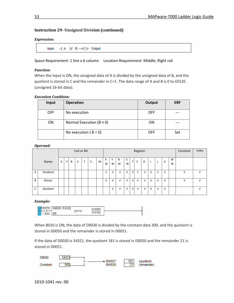
Instruction 29- Unsigned Division (continued)
Expression:
Space Requirement: 1 line x 6 column Location Requirement: Middle, Right rail
Function:
When the input is ON, the unsigned data of A is divided by the unsigned data of B, and the
quotient is stored in C and the remainder in C+1. The data range of A and B is 0 to 65535
(unsigned 16-bit data).
Execution Condition:
Input Operation Output ERF
OFF No execution OFF ---
ON Normal Execution (B ≠ 0) ON ---
No execution ( B = 0) OFF Set
Operand:
Coil or Bit Register Constant Index
Name X Y B S T. C. M
X
W
Y
W
B
W
S
W T C D I J K
M
W
A Dividend √ √ √ √ √ √ √ √ √ √ √ √
B Divisor √ √ √ √ √ √ √ √ √ √ √ √
C Quotient √ √ √ √ √ √ √ √ √ √
Example:
When B010 is ON, the data of D0030 is divided by the constant data 300, and the quotient is
stored in D0050 and the remainder is stored in D0051.
If the data of D0030 is 54321, the quotient 181 is stored in D0050 and the remainder 21 is
stored in D0051.

MAPware-7000 Ladder Logic Guide 54
1010-1041 rev. 00
Note:
If divisor (operand B) is 0, ERF (instruction error flag = S1010) is set to ON. The ERF (S1010) can be reset to OFF by user program, e.g. [ RST S1010 ].
If the index register K is used as operand C, the remainder is ignored.
This instruction handles the register data as unsigned integer.
55 MAPware-7000 Ladder Logic Guide
1010-1041 rev. 00
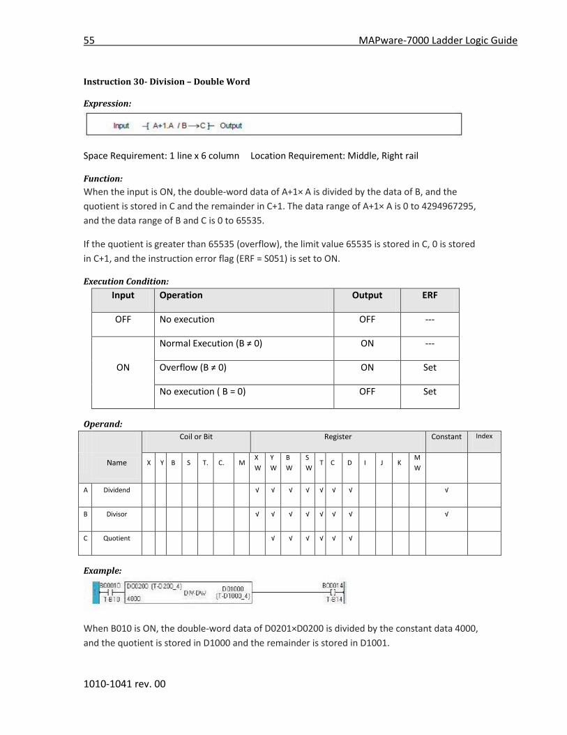
Instruction 30- Division – Double Word
Expression:
Space Requirement: 1 line x 6 column Location Requirement: Middle, Right rail
Function:
When the input is ON, the double-word data of A+1× A is divided by the data of B, and the
quotient is stored in C and the remainder in C+1. The data range of A+1× A is 0 to 4294967295,
and the data range of B and C is 0 to 65535.
If the quotient is greater than 65535 (overflow), the limit value 65535 is stored in C, 0 is stored
in C+1, and the instruction error flag (ERF = S051) is set to ON.
Execution Condition:
Input Operation Output ERF
OFF No execution OFF ---
Normal Execution (B ≠ 0) ON ---
ON Overflow (B ≠ 0) ON Set
No execution ( B = 0) OFF Set
Operand:
Coil or Bit Register Constant Index
Name X Y B S T. C. M
X
W
Y
W
B
W
S
W T C D I J K
M
W
A Dividend √ √ √ √ √ √ √ √
B Divisor √ √ √ √ √ √ √ √
C Quotient √ √ √ √ √ √
Example:
When B010 is ON, the double-word data of D0201×D0200 is divided by the constant data 4000,
and the quotient is stored in D1000 and the remainder is stored in D1001.

MAPware-7000 Ladder Logic Guide 56
1010-1041 rev. 00
If the data of D0201×D0200 is 332257, the quotient 83 is stored in D1000 and the remainder
257 is stored in D1001.
Note:
If the divisor (operand B) is 0, the ERF (instruction error flag = S1010) is set to ON. The ERF (S1010) can be reset to OFF by user program, e.g. [ RST S1010 ].
If the index register K is used as operand C, the remainder is ignored.
This instruction handles the register data as unsigned integer.

57 MAPware-7000 Ladder Logic Guide
1010-1041 rev. 00
Instruction 31- Addition with carry
Expression:
Space Requirement: 1 line x 6 column Location Requirement: Middle, Right rail
Function:
When the input is ON, the data of A, B and the carry flag (CF = S976) are added, and the result is
stored in C. If the carry occurs in the operation, the carry flag is set to ON. If the result is greater
than 32767 or smaller than -32768, the output is turned ON.
This instruction is used to perform unsigned addition or double-length addition.
Execution Condition:
Input Operation Output ERF
OFF No execution OFF ---
Normal No Carry OFF Reset
ON Execution Carry Occurred OFF Set
Overflow/ No Carry ON Reset
Underflow Carry Occurred ON Set
Operand:
Coil or Bit Register Constant Index
Name X Y B S T. C. M
X
W
Y
W
B
W
S
W T C D I J K
M
W
A Augend √ √ √ √ √ √ √ √ √ √ √ √
B Addend √ √ √ √ √ √ √ √ √ √ √ √
C Sum √ √ √ √ √ √ √ √ √
Example:

MAPware-7000 Ladder Logic Guide 58
1010-1041 rev. 00
When B013 is ON, the data of double-length registers D0100×D0101 and BW20×BW21 are
added, and the result is stored in D0201×D0200. The RSTC is a instruction to reset the carry flag
before starting the calculation.
If the data of D0100×D0101 is 12345678 and BW20×BW21 is 54322, the result 12400000 is
stored in D0201×D0200.

59 MAPware-7000 Ladder Logic Guide
1010-1041 rev. 00
Instruction 32- Subtraction with carry
Expression:
Space Requirement: 1 line x 6 column Location Requirement: Middle, Right rail
Function:
When the input is ON, the data of B and the carry flag (CF = S976) are subtracted from A, and
the result is stored in C. If a borrow occurs in the operation, the carry flag is set to ON. If the
result is greater than 32767 or smaller than -32768, the output is turned ON.
This instruction is used to perform unsigned subtraction or double-length subtraction.
Execution Condition:
Input Operation Output ERF
OFF No execution OFF ---
Normal No Borrow OFF Reset
ON Execution Borrow Occurred OFF Set
Overflow/ No Borrow ON Reset
Underflow Borrow Occurred ON Set
Operand:
Coil or Bit Register Constant Index
Name X Y B S T. C. M
X
W
Y
W
B
W
S
W T C D I J K
M
W
A Minuend √ √ √ √ √ √ √ √ √ √ √ √
B Subtrahend √ √ √ √ √ √ √ √ √ √ √ √
C Difference √ √ √ √ √ √ √ √ √ √
Example:

MAPware-7000 Ladder Logic Guide 60
1010-1041 rev. 00
When B013 is ON, the data of double-length register BW23×BW22 is subtracted from the data
of D0201×D0200, and the result is stored in D0211×D0210. The RSTC is a instruction to reset the
carry flag before starting the calculation.
If the data of D0200×D0201 is 12345678 and BW22×BW23 is 12340000, the result 5678 is stored
in D0210×D0211.

61 MAPware-7000 Ladder Logic Guide
1010-1041 rev. 00
Instruction 33- Increment
Expression:
Space Requirement: 1 line x 3 column Location Requirement: Middle, Right rail
Function:
When the input is ON, the data of A is increased by 1 and stored in A.
Execution Condition:
Input Operation Output
OFF No execution OFF
ON Execution ON
Operand:
Coil or Bit Register Constant Index
Name X Y B S T. C. M
X
W
Y
W
B
W
S
W T C D I J K
M
W
A Operation
Data √ √ √ √ √ √ √ √ √ √
Example:
At the rising edge of X004 changes from OFF to ON, the data of D0050 is increased by 1 and
stored in D0050.
If the data of D0050 is 750 before the execution, it will be 751 after the execution.
Note:
There is no limit value for this instruction. When the data of operand A is 32767 before the
execution, it will be -32768 after the execution

MAPware-7000 Ladder Logic Guide 62
1010-1041 rev. 00
Instruction 34- Decrement
Expression:
Space Requirement: 1 line x 3 column Location Requirement: Middle, Right rail
Function:
When the input is ON, the data of A is decreased by 1 and stored in A.
Execution Condition:
Input Operation Output
OFF No execution OFF
ON Execution ON
Operand:
Coil or Bit Register Constant Index
Name X Y B S T. C. M
X
W
Y
W
B
W
S
W T C D I J K
M
W
A Operation
Data √ √ √ √ √ √ √ √ √ √
Example:
At the rising edge of X005 changes from OFF to ON, the data of D0050 is decreased by 1 and
stored in D0050.
If the data of D0050 is 1022 before the execution, it will be 1021 after the execution.
Note:
There is no limit value for this instruction. When the data of operand A is -32768 before the
execution, it will be 32767 after the execution
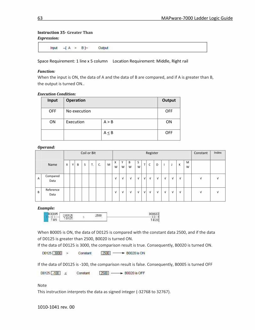
63 MAPware-7000 Ladder Logic Guide
1010-1041 rev. 00
Instruction 35- Greater Than
Expression:
Space Requirement: 1 line x 5 column Location Requirement: Middle, Right rail
Function:
When the input is ON, the data of A and the data of B are compared, and if A is greater than B,
the output is turned ON..
Execution Condition:
Input Operation Output
OFF No execution OFF
ON Execution A > B ON
A < B OFF
Operand:
Coil or Bit Register Constant Index
Name X Y B S T. C. M
X
W
Y
W
B
W
S
W T C D I J K
M
W
A Compared
Data √ √ √ √ √ √ √ √ √ √ √ √
B Reference
Data √ √ √ √ √ √ √ √ √ √ √ √
Example:
When B0005 is ON, the data of D0125 is compared with the constant data 2500, and if the data
of D0125 is greater than 2500, B0020 is turned ON.
If the data of D0125 is 3000, the comparison result is true. Consequently, B0020 is turned ON.
If the data of D0125 is -100, the comparison result is false. Consequently, B0005 is turned OFF
Note
This instruction interprets the data as signed integer (-32768 to 32767).
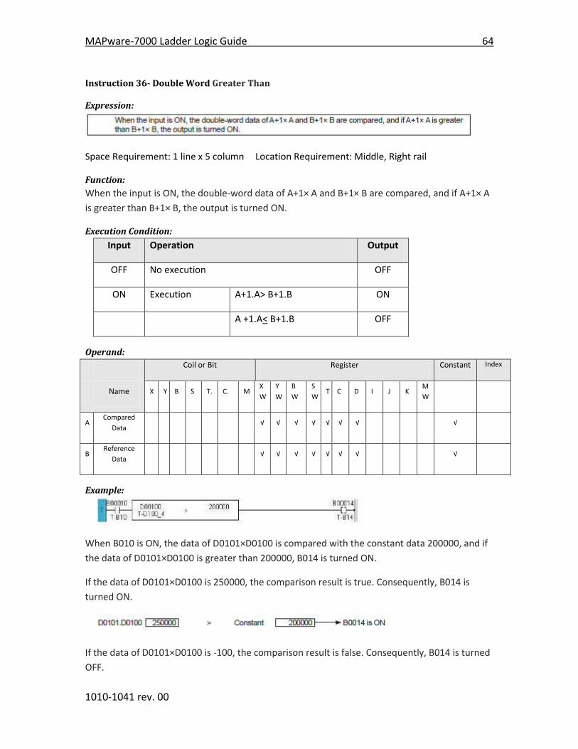
MAPware-7000 Ladder Logic Guide 64
1010-1041 rev. 00
Instruction 36- Double Word Greater Than
Expression:
Space Requirement: 1 line x 5 column Location Requirement: Middle, Right rail
Function:
When the input is ON, the double-word data of A+1× A and B+1× B are compared, and if A+1× A
is greater than B+1× B, the output is turned ON.
Execution Condition:
Input Operation Output
OFF No execution OFF
ON Execution A+1.A> B+1.B ON
A +1.A< B+1.B OFF
Operand:
Coil or Bit Register Constant Index
Name X Y B S T. C. M
X
W
Y
W
B
W
S
W T C D I J K
M
W
A Compared
Data √ √ √ √ √ √ √ √
B Reference
Data √ √ √ √ √ √ √ √
Example:
When B010 is ON, the data of D0101×D0100 is compared with the constant data 200000, and if
the data of D0101×D0100 is greater than 200000, B014 is turned ON.
If the data of D0101×D0100 is 250000, the comparison result is true. Consequently, B014 is
turned ON.
If the data of D0101×D0100 is -100, the comparison result is false. Consequently, B014 is turned
OFF.

65 MAPware-7000 Ladder Logic Guide
1010-1041 rev. 00
Note
This instruction interprets the data as double word integer (-2147483648 to 2147483648).

MAPware-7000 Ladder Logic Guide 66
1010-1041 rev. 00
Instruction 37- Unsigned Word Greater Than
Expression:
Space Requirement: 1 line x 5 column Location Requirement: Middle, Right rail
Function:
When the input is ON, the data of A and the data of B are compared, and if A is greater than B,
the output is turned ON.
Execution Condition:
Input Operation Output
OFF No execution OFF
ON Execution A > B ON
A < B OFF
Operand:
Coil or Bit Register Constant Index
Name X Y B S T. C. M
X
W
Y
W
B
W
S
W T C D I J K
M
W
A Compared
Data √ √ √ √ √ √ √ √ √ √ √ √
B Reference
Data √ √ √ √ √ √ √ √ √ √ √ √
Example:
When B0005 is ON, the data of D0125 is compared with the constant data 40000, and if the data
of D0125 is greater than 40000, B0020 is turned ON.
If the data of D0125 is 52000, the comparison result is true. Consequently, B0020 is turned ON.
If the data of D0125 is 21000, the comparison result is false. Consequently, B0005 is turned OFF.
Note
This instruction deals with the data as unsigned integer (0 to 65535).
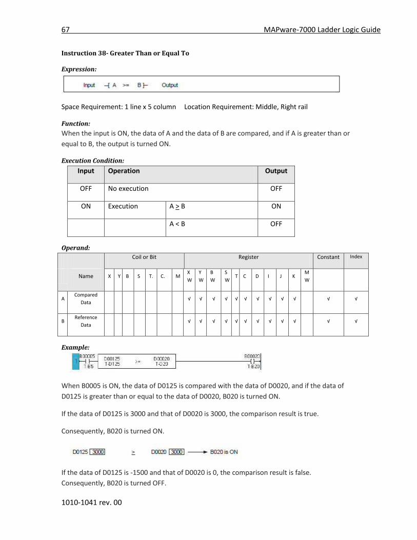
67 MAPware-7000 Ladder Logic Guide
1010-1041 rev. 00
Instruction 38- Greater Than or Equal To
Expression:
Space Requirement: 1 line x 5 column Location Requirement: Middle, Right rail
Function:
When the input is ON, the data of A and the data of B are compared, and if A is greater than or
equal to B, the output is turned ON.
Execution Condition:
Input Operation Output
OFF No execution OFF
ON Execution A > B ON
A < B OFF
Operand:
Coil or Bit Register Constant Index
Name X Y B S T. C. M
X
W
Y
W
B
W
S
W T C D I J K
M
W
A Compared
Data √ √ √ √ √ √ √ √ √ √ √ √
B Reference
Data √ √ √ √ √ √ √ √ √ √ √ √
Example:
When B0005 is ON, the data of D0125 is compared with the data of D0020, and if the data of
D0125 is greater than or equal to the data of D0020, B020 is turned ON.
If the data of D0125 is 3000 and that of D0020 is 3000, the comparison result is true.
Consequently, B020 is turned ON.
If the data of D0125 is -1500 and that of D0020 is 0, the comparison result is false.
Consequently, B020 is turned OFF.

MAPware-7000 Ladder Logic Guide 68
1010-1041 rev. 00
Note
This instruction interprets the data as signed integer (-32768 to 32767).

69 MAPware-7000 Ladder Logic Guide
1010-1041 rev. 00
Instruction 39- Double Word Greater Than or Equal To
Expression:
Space Requirement: 1 line x 5 column Location Requirement: Middle, Right rail
Function:
When the input is ON, the data of A+1 X A and the data of B+1 X B are compared, and if A+1.A is
greater than or equal to B+1.B, the output is turned ON.
Execution Condition:
Input Operation Output
OFF No execution OFF
ON Execution A+1.A > B+1.B ON
A+1.A < B+1.B OFF
Operand:
Coil or Bit Register Constant Index
Name X Y B S T. C. M
X
W
Y
W
B
W
S
W T C D I J K
M
W
A Compared
Data √ √ √ √ √ √ √ √
B Reference
Data √ √ √ √ √ √ √ √
Example:
When B010 is ON, the double-word data of D0101×D0100 is compared with the double-word
data of D0251×D0250, and if the data of D0101×D0100 is greater than or equal to the data of
D0251×D0250, B014 is turned ON.
If the data of D0101×D0100 is 250000 and D0251×D0250 is 200000, B014 is turned ON.
If the data of D0101xD100 is -100 and that of D0251xD0250 is 0, the comparison result is false.
Consequently, B014 is turned OFF.

MAPware-7000 Ladder Logic Guide 70
1010-1041 rev. 00
Note
This instruction interprets the data as double word integer (-2147483648 to 2147483648).

71 MAPware-7000 Ladder Logic Guide
1010-1041 rev. 00
Instruction 40- Unsigned Greater Than or Equal To
Expression:
Space Requirement: 1 line x 5 column Location Requirement: Middle, Right rail
Function:
When the input is ON, the data of A and the data of B are compared, and if A is greater than or
equal to B, the output is turned ON.
Execution Condition:
Input Operation Output
OFF No execution OFF
ON Execution A > B ON
A < B OFF
Operand:
Coil or Bit Register Constant Index
Name X Y B S T. C. M
X
W
Y
W
B
W
S
W T C D I J K
M
W
A Compared
Data √ √ √ √ √ √ √ √ √ √ √ √
B Reference
Data √ √ √ √ √ √ √ √ √ √ √ √
Example:
When B0005 is ON, the data of D0125 is compared with the data of D0020, and if the data of
D0125 is greater than or equal to the data of D0020, B020 is turned ON.
If the data of D0125 is 3000 and that of D0020 is 3000, the comparison result is true.
Consequently, B020 is turned ON.
If the data of D0125 is -1500 and that of D0020 is 0, the comparison result is false.
Consequently, B020 is turned OFF.

MAPware-7000 Ladder Logic Guide 72
1010-1041 rev. 00
Note
This instruction interprets the data as unsigned integer (0 to 65535).
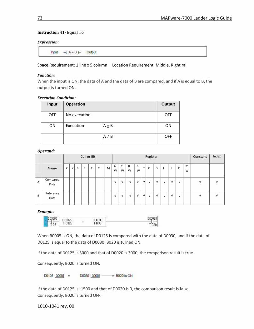
73 MAPware-7000 Ladder Logic Guide
1010-1041 rev. 00
Instruction 41- Equal To
Expression:
Space Requirement: 1 line x 5 column Location Requirement: Middle, Right rail
Function:
When the input is ON, the data of A and the data of B are compared, and if A is equal to B, the
output is turned ON.
Execution Condition:
Input Operation Output
OFF No execution OFF
ON Execution A = B ON
A ≠ B OFF
Operand:
Coil or Bit Register Constant Index
Name X Y B S T. C. M
X
W
Y
W
B
W
S
W T C D I J K
M
W
A Compared
Data √ √ √ √ √ √ √ √ √ √ √ √
B Reference
Data √ √ √ √ √ √ √ √ √ √ √ √
Example:
When B0005 is ON, the data of D0125 is compared with the data of D0030, and if the data of
D0125 is equal to the data of D0030, B020 is turned ON.
If the data of D0125 is 3000 and that of D0020 is 3000, the comparison result is true.
Consequently, B020 is turned ON.
If the data of D0125 is -1500 and that of D0020 is 0, the comparison result is false.
Consequently, B020 is turned OFF.

MAPware-7000 Ladder Logic Guide 74
1010-1041 rev. 00
Note
This instruction interprets the data as signed integer (-32768 to 32767).
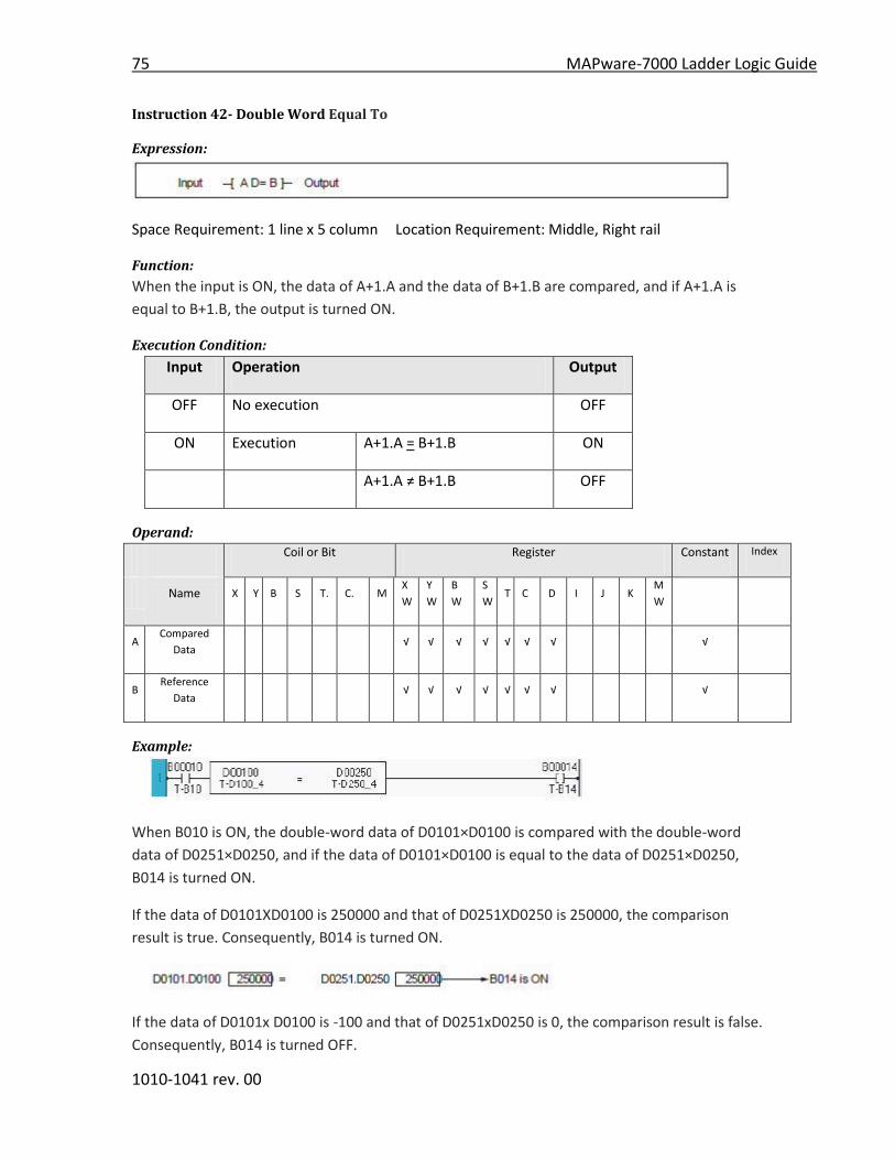
75 MAPware-7000 Ladder Logic Guide
1010-1041 rev. 00
Instruction 42- Double Word Equal To
Expression:
Space Requirement: 1 line x 5 column Location Requirement: Middle, Right rail
Function:
When the input is ON, the data of A+1.A and the data of B+1.B are compared, and if A+1.A is
equal to B+1.B, the output is turned ON.
Execution Condition:
Input Operation Output
OFF No execution OFF
ON Execution A+1.A = B+1.B ON
A+1.A ≠ B+1.B OFF
Operand:
Coil or Bit Register Constant Index
Name X Y B S T. C. M
X
W
Y
W
B
W
S
W T C D I J K
M
W
A Compared
Data √ √ √ √ √ √ √ √
B Reference
Data √ √ √ √ √ √ √ √
Example:
When B010 is ON, the double-word data of D0101×D0100 is compared with the double-word
data of D0251×D0250, and if the data of D0101×D0100 is equal to the data of D0251×D0250,
B014 is turned ON.
If the data of D0101XD0100 is 250000 and that of D0251XD0250 is 250000, the comparison
result is true. Consequently, B014 is turned ON.
If the data of D0101x D0100 is -100 and that of D0251xD0250 is 0, the comparison result is false.
Consequently, B014 is turned OFF.

MAPware-7000 Ladder Logic Guide 76
1010-1041 rev. 00
Note
This instruction interprets the data as double word integer (-2147483648 to 2147483648).

77 MAPware-7000 Ladder Logic Guide
1010-1041 rev. 00
Instruction 43- Unsigned Equal To
Expression:
Space Requirement: 1 line x 5 column Location Requirement: Middle, Right rail
Function:
When the input is ON, the data of A and the data of B are compared, and if A is equal to B, the
output is turned ON.
Execution Condition:
Input Operation Output
OFF No execution OFF
ON Execution A = B ON
A ≠ B OFF
Operand:
Coil or Bit Register Constant Index
Name X Y B S T. C. M
X
W
Y
W
B
W
S
W T C D I J K
M
W
A Compared
Data √ √ √ √ √ √ √ √ √ √ √ √
B Reference
Data √ √ √ √ √ √ √ √ √ √ √ √
Example:
When B0005 is ON, the data of D0125 is compared with the data of D0030, and if the data of
D0125 is equal to the data of D0030, B020 is turned ON.
If the data of D0125 is 35000 and that of D0020 is 35000, the comparison result is true.
Consequently, B020 is turned ON.
If the data of D0125 is 1500 and that of D0020 is 4000, the comparison result is false.

MAPware-7000 Ladder Logic Guide 78
1010-1041 rev. 00
Consequently, B020 is turned OFF.
Note
This instruction deals with the data as unsigned integer (0 to 65535).
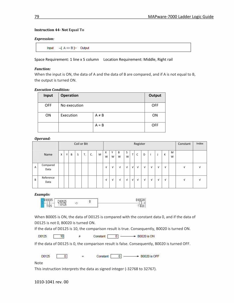
79 MAPware-7000 Ladder Logic Guide
1010-1041 rev. 00
Instruction 44- Not Equal To
Expression:
Space Requirement: 1 line x 5 column Location Requirement: Middle, Right rail
Function:
When the input is ON, the data of A and the data of B are compared, and if A is not equal to B,
the output is turned ON.
Execution Condition:
Input Operation Output
OFF No execution OFF
ON Execution A ≠ B ON
A = B OFF
Operand:
Coil or Bit Register Constant Index
Name X Y B S T. C. M
X
W
Y
W
B
W
S
W T C D I J K
M
W
A Compared
Data √ √ √ √ √ √ √ √ √ √ √ √
B Reference
Data √ √ √ √ √ √ √ √ √ √ √ √
Example:
When B0005 is ON, the data of D0125 is compared with the constant data 0, and if the data of
D0125 is not 0, B0020 is turned ON.
If the data of D0125 is 10, the comparison result is true. Consequently, B0020 is turned ON.
If the data of D0125 is 0, the comparison result is false. Consequently, B0020 is turned OFF.
Note
This instruction interprets the data as signed integer (-32768 to 32767).

MAPware-7000 Ladder Logic Guide 80
1010-1041 rev. 00
Instruction 45- Double Word Not Equal To
Expression:
Space Requirement: 1 line x 5 column Location Requirement: Middle, Right rail
Function:
When the input is ON, the data of A+1.A and the data of B+1.B are compared, and if A+1.A is not
equal to B+1.B, the output is turned ON.
Execution Condition:
Input Operation Output
OFF No execution OFF
ON Execution A+1.A ≠ B+1.B ON
A+1.A = B+1.B OFF
Operand:
Coil or Bit Register Constant Index
Name X Y B S T. C. M
X
W
Y
W
B
W
S
W T C D I J K
M
W
A Compared
Data √ √ √ √ √ √ √ √
B Reference
Data √ √ √ √ √ √ √ √
Example:
When B010 is ON, the double-word data of D0101×D0100 is compared with the double-word
data of D0251×D0250, and if the data of D0101×D0100 is not equal to the data of
D0251×D0250, B014 is turned ON.
If the data of D0101.D0100 is 250000 and D0251xD0250 is 200000, B014 is turned ON.
If the data of D0101.D0100 is -100 and D0251.D0250 is -100, B014 is turned OFF.

81 MAPware-7000 Ladder Logic Guide
1010-1041 rev. 00
Note
This instruction interprets the data as double word integer (-2147483648 to 2147483648).
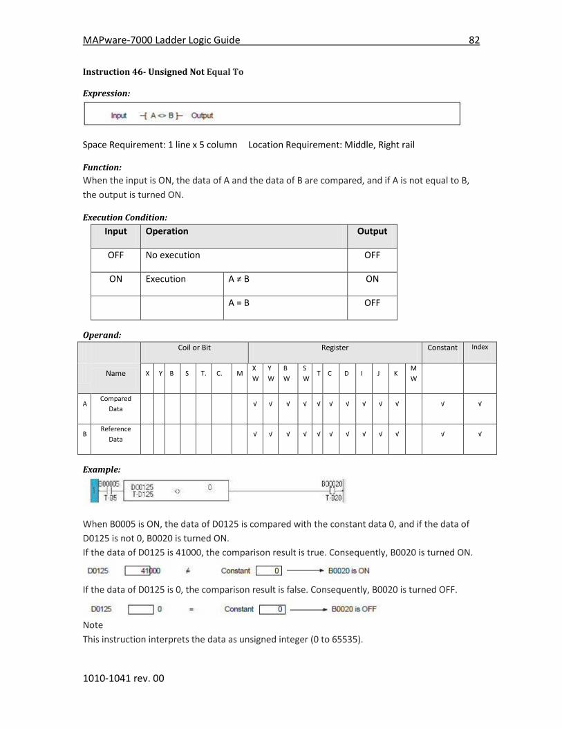
MAPware-7000 Ladder Logic Guide 82
1010-1041 rev. 00
Instruction 46- Unsigned Not Equal To
Expression:
Space Requirement: 1 line x 5 column Location Requirement: Middle, Right rail
Function:
When the input is ON, the data of A and the data of B are compared, and if A is not equal to B,
the output is turned ON.
Execution Condition:
Input Operation Output
OFF No execution OFF
ON Execution A ≠ B ON
A = B OFF
Operand:
Coil or Bit Register Constant Index
Name X Y B S T. C. M
X
W
Y
W
B
W
S
W T C D I J K
M
W
A Compared
Data √ √ √ √ √ √ √ √ √ √ √ √
B Reference
Data √ √ √ √ √ √ √ √ √ √ √ √
Example:
When B0005 is ON, the data of D0125 is compared with the constant data 0, and if the data of
D0125 is not 0, B0020 is turned ON.
If the data of D0125 is 41000, the comparison result is true. Consequently, B0020 is turned ON.
If the data of D0125 is 0, the comparison result is false. Consequently, B0020 is turned OFF.
Note
This instruction interprets the data as unsigned integer (0 to 65535).
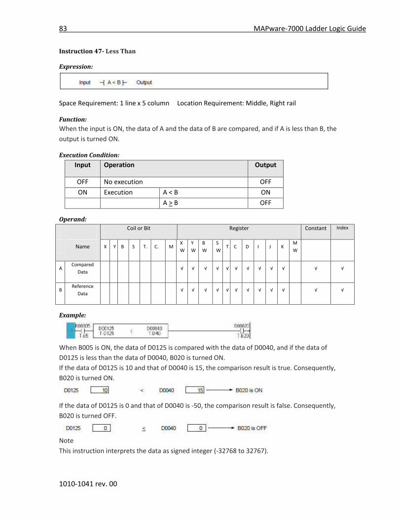
83 MAPware-7000 Ladder Logic Guide
1010-1041 rev. 00
Instruction 47- Less Than
Expression:
Space Requirement: 1 line x 5 column Location Requirement: Middle, Right rail
Function:
When the input is ON, the data of A and the data of B are compared, and if A is less than B, the
output is turned ON.
Execution Condition:
Input Operation Output
OFF No execution OFF
ON Execution A < B ON
A > B OFF
Operand:
Coil or Bit Register Constant Index
Name X Y B S T. C. M
X
W
Y
W
B
W
S
W T C D I J K
M
W
A Compared
Data √ √ √ √ √ √ √ √ √ √ √ √
B Reference
Data √ √ √ √ √ √ √ √ √ √ √ √
Example:
When B005 is ON, the data of D0125 is compared with the data of D0040, and if the data of
D0125 is less than the data of D0040, B020 is turned ON.
If the data of D0125 is 10 and that of D0040 is 15, the comparison result is true. Consequently,
B020 is turned ON.
If the data of D0125 is 0 and that of D0040 is -50, the comparison result is false. Consequently,
B020 is turned OFF.
Note
This instruction interprets the data as signed integer (-32768 to 32767).

MAPware-7000 Ladder Logic Guide 84
1010-1041 rev. 00

85 MAPware-7000 Ladder Logic Guide
1010-1041 rev. 00
Instruction 48- Double Word Less Than
Expression:
Space Requirement: 1 line x 5 column Location Requirement: Middle, Right rail
Function:
When the input is ON, the data of A+1.A and the data of B+1.B are compared, and if A+1.A is less
than B+1.B, the output is turned ON.
Execution Condition:
Input Operation Output
OFF No execution OFF
ON Execution A+1.A< B+1.B ON
A +1.A> B+1.B OFF
Operand:
Coil or Bit Register Constant Index
Name X Y B S T. C. M
X
W
Y
W
B
W
S
W T C D I J K
M
W
A Compared
Data √ √ √ √ √ √ √ √
B Reference
Data √ √ √ √ √ √ √ √
Example:
When B010 is ON, the data of D0101.D0100 is compared with the constant data 427780, and if
the data of D0101.D0100 is less than the data 427780, B014 is turned ON.
If the data of D0101.D0100 is 250000 B014 is turned ON.
If the data of D0101Xd100 is 430000, B014 is turned OFF.
Note
This instruction interprets the data as double word integer (-2147483648 to 2147483648).

MAPware-7000 Ladder Logic Guide 86
1010-1041 rev. 00
Instruction 49- Unsigned Less Than
Expression:
Space Requirement: 1 line x 5 column Location Requirement: Middle, Right rail
Function:
When the input is ON, the data of A and the data of B are compared, and if A is less than B, the
output is turned ON.
Execution Condition:
Input Operation Output
OFF No execution OFF
ON Execution A < B ON
A > B OFF
Operand:
Coil or Bit Register Constant Index
Name X Y B S T. C. M
X
W
Y
W
B
W
S
W T C D I J K
M
W
A Compared
Data √ √ √ √ √ √ √ √ √ √ √ √
B Reference
Data √ √ √ √ √ √ √ √ √ √ √ √
Example:
When B005 is ON, the data of D0125 is compared with the data of D0040, and if the data of
D0125 is less than the data of D0040, B020 is turned ON.
If the data of D0125 is 43000 and that of D0040 is 45000, the comparison result is true.
Consequently, B020 is turned ON.
If the data of D0125 is 50000 and that of D0040 is 50000, the comparison result is false.
Consequently, B020 is turned OFF.
Note
This instruction deals with the data as unsigned integer (0 to 65535).

87 MAPware-7000 Ladder Logic Guide
1010-1041 rev. 00
Instruction 50- Less Than or Equal To
Expression:
Space Requirement: 1 line x 5 column Location Requirement: Middle, Right rail
Function:
When the input is ON, the data of A and the data of B are compared, and if A is less than or
equal to B, the output is turned ON.
Execution Condition:
Input Operation Output
OFF No execution OFF
ON Execution A < B ON
A > B OFF
Operand:
Coil or Bit Register Constant Index
Name X Y B S T. C. M
X
W
Y
W
B
W
S
W T C D I J K
M
W
A Compared
Data √ √ √ √ √ √ √ √ √ √ √ √
B Reference
Data √ √ √ √ √ √ √ √ √ √ √ √
Example:
When B0005 is ON, the data of D0125 is compared with the constant data -100, and if the data
of D0125 is less than or equal to -100, B020 is turned ON.
If the data of D0125 is -150, the comparison result is true. Consequently, B020 is turned ON.
If the data of D0125 is 0, the comparison result is false. Consequently, B0020 is turned OFF.
Note
This instruction interprets the data as signed integer (-32768 to 32767).
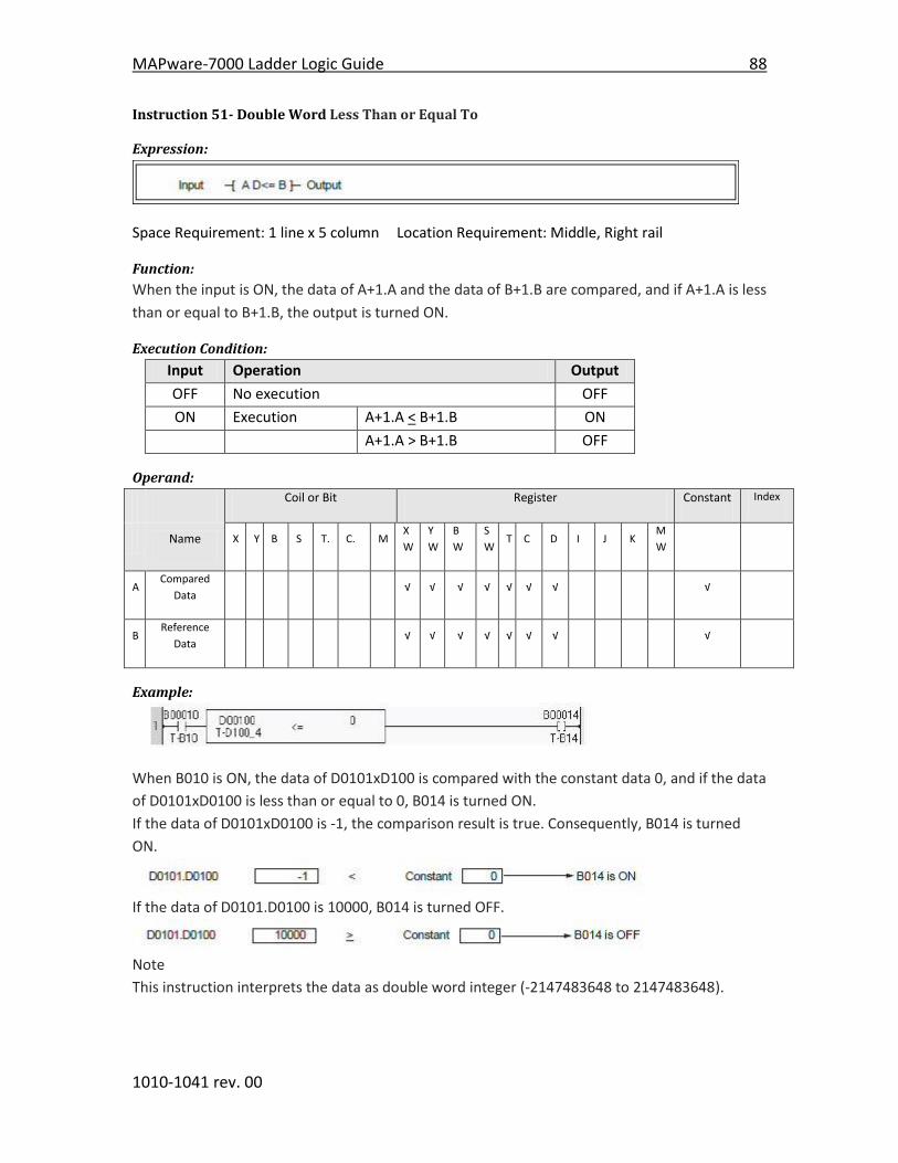
MAPware-7000 Ladder Logic Guide 88
1010-1041 rev. 00
Instruction 51- Double Word Less Than or Equal To
Expression:
Space Requirement: 1 line x 5 column Location Requirement: Middle, Right rail
Function:
When the input is ON, the data of A+1.A and the data of B+1.B are compared, and if A+1.A is less
than or equal to B+1.B, the output is turned ON.
Execution Condition:
Input Operation Output
OFF No execution OFF
ON Execution A+1.A < B+1.B ON
A+1.A > B+1.B OFF
Operand:
Coil or Bit Register Constant Index
Name X Y B S T. C. M
X
W
Y
W
B
W
S
W T C D I J K
M
W
A Compared
Data √ √ √ √ √ √ √ √
B Reference
Data √ √ √ √ √ √ √ √
Example:
When B010 is ON, the data of D0101xD100 is compared with the constant data 0, and if the data
of D0101xD0100 is less than or equal to 0, B014 is turned ON.
If the data of D0101xD0100 is -1, the comparison result is true. Consequently, B014 is turned
ON.
If the data of D0101.D0100 is 10000, B014 is turned OFF.
Note
This instruction interprets the data as double word integer (-2147483648 to 2147483648).

89 MAPware-7000 Ladder Logic Guide
1010-1041 rev. 00
Instruction 52- Unsigned Less Than or Equal To
Expression:
Space Requirement: 1 line x 5 column Location Requirement: Middle, Right rail
Function:
When the input is ON, the data of A and the data of B are compared, and if A is less than or
equal to B, the output is turned ON.
Execution Condition:
Input Operation Output
OFF No execution OFF
ON Execution A < B ON
A > B OFF
Operand:
Coil or Bit Register Constant Index
Name X Y B S T. C. M
X
W
Y
W
B
W
S
W T C D I J K
M
W
A Compared
Data √ √ √ √ √ √ √ √ √ √ √ √
B Reference
Data √ √ √ √ √ √ √ √ √ √ √ √
Example:
When B0005 is ON, the data of D0125 is compared with the constant data 35000, and if the data
of D0125 is less than or equal to 35000, B020 is turned ON.
If the data of D0125 is 35000, the comparison result is true. Consequently, B020 is turned ON.
If the data of D0125 is 0, the comparison result is false. Consequently, B0020 is turned OFF.
Note
This instruction interprets the data as unsigned integer (0 to 65535).
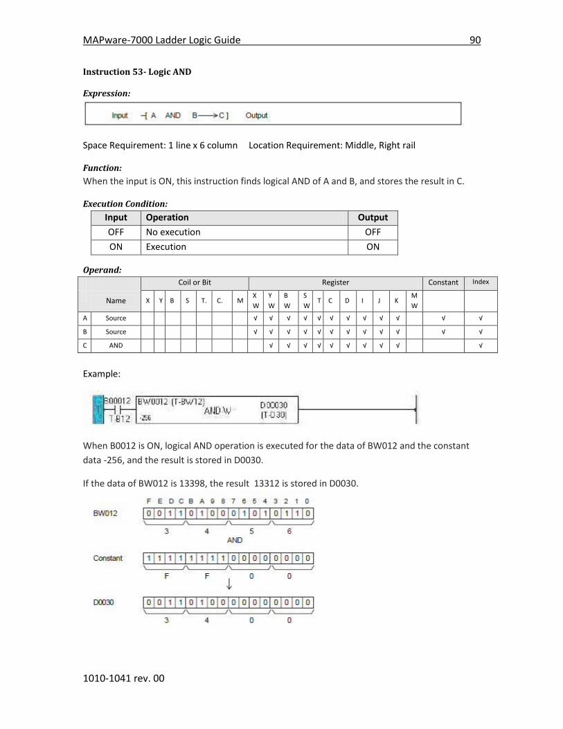
MAPware-7000 Ladder Logic Guide 90
1010-1041 rev. 00
Instruction 53- Logic AND
Expression:
Space Requirement: 1 line x 6 column Location Requirement: Middle, Right rail
Function:
When the input is ON, this instruction finds logical AND of A and B, and stores the result in C.
Execution Condition:
Input Operation Output
OFF No execution OFF
ON Execution ON
Operand:
Coil or Bit Register Constant Index
Name X Y B S T. C. M
X
W
Y
W
B
W
S
W T C D I J K
M
W
A Source √ √ √ √ √ √ √ √ √ √ √ √
B Source √ √ √ √ √ √ √ √ √ √ √ √
C AND √ √ √ √ √ √ √ √ √ √
Example:
When B0012 is ON, logical AND operation is executed for the data of BW012 and the constant
data -256, and the result is stored in D0030.
If the data of BW012 is 13398, the result 13312 is stored in D0030.

91 MAPware-7000 Ladder Logic Guide
1010-1041 rev. 00
Instruction 54- Logic OR
Expression:
Space Requirement: 1 line x 6 column Location Requirement: Middle, Right rail
Function:
When the input is ON, this instruction finds logical OR of A and B, and stores the result in C.
Execution Condition:
Input Operation Output
OFF No execution OFF
ON Execution ON
Operand:
Coil or Bit Register Constant Index
Name X Y B S T. C. M
X
W
Y
W
B
W
S
W T C D I J K
M
W
A Source √ √ √ √ √ √ √ √ √ √ √ √
B Source √ √ √ √ √ √ √ √ √ √ √ √
C AND √ √ √ √ √ √ √ √ √ √
Example:
When B012 is ON, logical OR operation is executed for the data of BW13 and BW20, and the
result is stored in D0031.
If the data of BW13 is H5678 and BW20 is H4321, the result H5779 is stored in D0031.
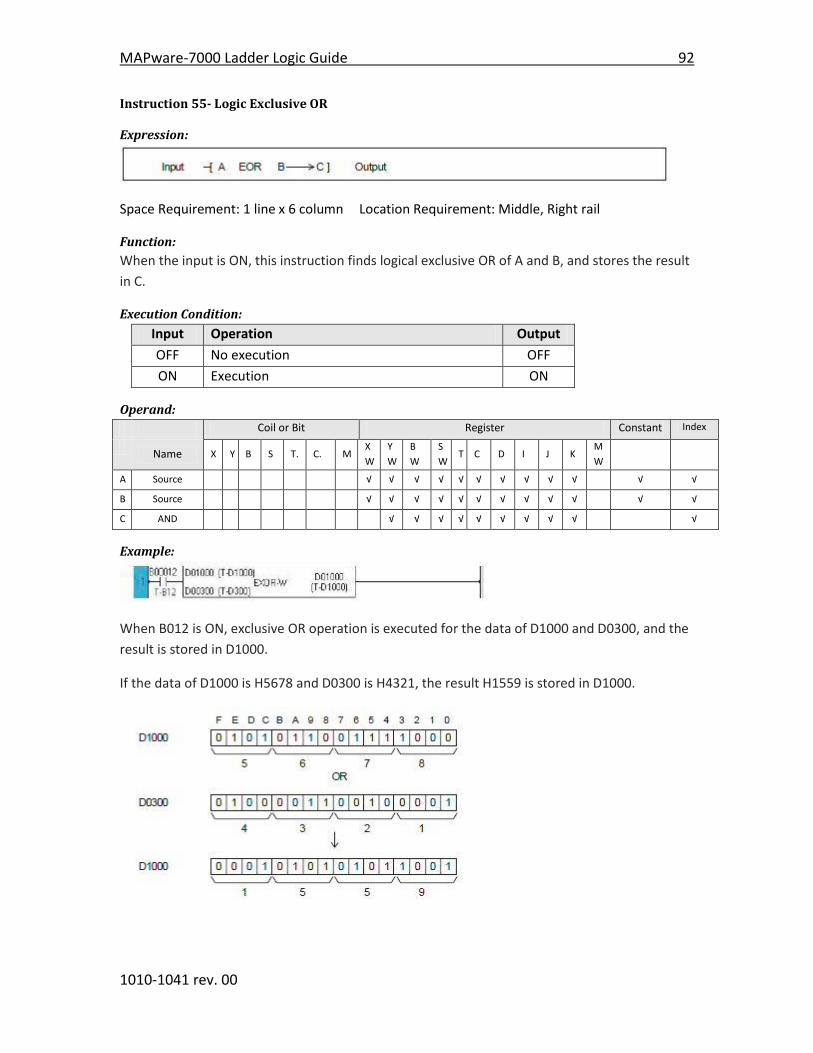
MAPware-7000 Ladder Logic Guide 92
1010-1041 rev. 00
Instruction 55- Logic Exclusive OR
Expression:
Space Requirement: 1 line x 6 column Location Requirement: Middle, Right rail
Function:
When the input is ON, this instruction finds logical exclusive OR of A and B, and stores the result
in C.
Execution Condition:
Input Operation Output
OFF No execution OFF
ON Execution ON
Operand:
Coil or Bit Register Constant Index
Name X Y B S T. C. M
X
W
Y
W
B
W
S
W T C D I J K
M
W
A Source √ √ √ √ √ √ √ √ √ √ √ √
B Source √ √ √ √ √ √ √ √ √ √ √ √
C AND √ √ √ √ √ √ √ √ √ √
Example:
When B012 is ON, exclusive OR operation is executed for the data of D1000 and D0300, and the
result is stored in D1000.
If the data of D1000 is H5678 and D0300 is H4321, the result H1559 is stored in D1000.

93 MAPware-7000 Ladder Logic Guide
1010-1041 rev. 00
Instruction 56- Logic Shift – 1 bit shift right
Expression:
Space Requirement: 1 line x 3 column Location Requirement: Middle, Right rail
Function:
When the input is ON, the data of register A is shifted 1 bit to the right (LSB direction). 0 is
stored in the left most bit (MSB). The pushed out bit state is stored in the carry flag (CF = S976).
After the operation, if the right most bit (LSB) is ON, the output is turned ON.
Execution Condition:
Input Operation Output CF
OFF No execution OFF ---
Execution When LSB = 1 ON Set or Reset
ON When LSB = 0 OFF Set or Reset
Operand:
Coil or Bit Register Constant Index
Name X Y B S T. C. M
X
W
Y
W
B
W
S
W T C D I J K
M
W
A Operation
Data √ √ √ √ √ √ √ √ √ √
Example:
When X007 is changed from OFF to ON, the data of BW15 is shifted 1 bit to the right.
The figure below shows an operation example.

MAPware-7000 Ladder Logic Guide 94
1010-1041 rev. 00
Instruction 57- Logic Shift – 1 bit shift left
Expression:
Space Requirement: 1 line x 3 column Location Requirement: Middle, Right rail
Function:
When the input is ON, the data of register A is shifted 1 bit to the left (MSB direction). 0 is
stored in the right most bit (LSB). The pushed out bit state is stored in the carry flag (CF = S976).
After the operation, if the left most bit (MSB) is ON, the output is turned ON.
Execution Condition:
Input Operation Output CF
OFF No execution OFF ---
ON Execution When MSB = 1 ON Set or Reset
When MSB = 0 OFF Set or Reset
Operand:
Coil or Bit Register Constant Index
Name X Y B S T. C. M
X
W
Y
W
B
W
S
W T C D I J K
M
W
A Operation
Data √ √ √ √ √ √ √ √ √ √
Example:
When X008 is changed from OFF to ON, the data of BW15 is shifted 1 bit to the left.
The figure below shows an operation example.
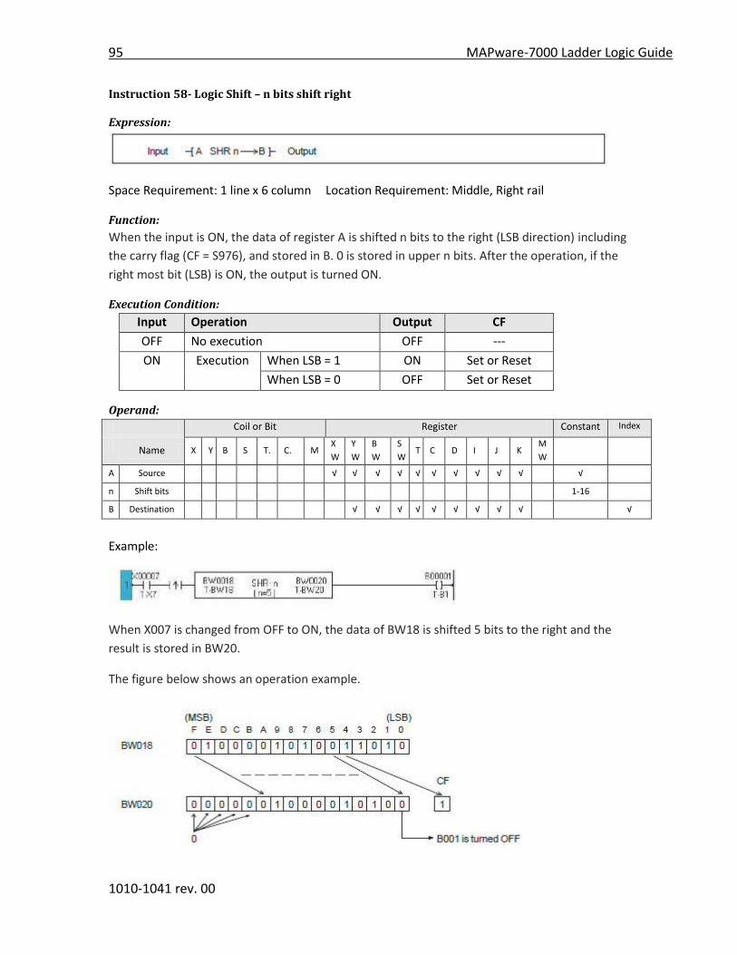
95 MAPware-7000 Ladder Logic Guide
1010-1041 rev. 00
Instruction 58- Logic Shift – n bits shift right
Expression:
Space Requirement: 1 line x 6 column Location Requirement: Middle, Right rail
Function:
When the input is ON, the data of register A is shifted n bits to the right (LSB direction) including
the carry flag (CF = S976), and stored in B. 0 is stored in upper n bits. After the operation, if the
right most bit (LSB) is ON, the output is turned ON.
Execution Condition:
Input Operation Output CF
OFF No execution OFF ---
ON Execution When LSB = 1 ON Set or Reset
When LSB = 0 OFF Set or Reset
Operand:
Coil or Bit Register Constant Index
Name X Y B S T. C. M
X
W
Y
W
B
W
S
W T C D I J K
M
W
A Source √ √ √ √ √ √ √ √ √ √ √
n Shift bits 1-16
B Destination √ √ √ √ √ √ √ √ √ √
Example:
When X007 is changed from OFF to ON, the data of BW18 is shifted 5 bits to the right and the
result is stored in BW20.
The figure below shows an operation example.

MAPware-7000 Ladder Logic Guide 96
1010-1041 rev. 00
Instruction 59- Logic Shift – n bits shift left
Expression:
Space Requirement: 1 line x 6 column Location Requirement: Middle, Right rail
Function:
When the input is ON, the data of register A is shifted n bits to the left (MSB direction) including
the carry flag (CF = S976), and stored in B. 0 is stored in lower n bits. After the operation, if the
left most bit (MSB) is ON, the output is turned ON.
Execution Condition:
Input Operation Output CF
OFF No execution OFF ---
ON Execution When MSB = 1 ON Set or Reset
When MSB = 0 OFF Set or Reset
Operand:
Coil or Bit Register Constant Index
Name X Y B S T. C. M
X
W
Y
W
B
W
S
W T C D I J K
M
W
A Source √ √ √ √ √ √ √ √ √ √ √ √
n Shift bits 1-16
B Destination √ √ √ √ √ √ √ √ √ √
Example:
When X007 is changed from OFF to ON, the data of BW18 is shifted 3 bits to the left and the
result is stored in BW20.
The figure below shows an operation example.
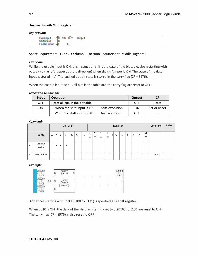
97 MAPware-7000 Ladder Logic Guide
1010-1041 rev. 00
Instruction 60- Shift Register
Expression:
Space Requirement: 3 line x 3 column Location Requirement: Middle, Right rail
Function:
While the enable input is ON, this instruction shifts the data of the bit table, size n starting with
A, 1 bit to the left (upper address direction) when the shift input is ON. The state of the data
input is stored in A. The pushed out bit state is stored in the carry flag (CF = S976).
When the enable input is OFF, all bits in the table and the carry flag are reset to OFF.
Execution Condition:
Input Operation Output CF
OFF Reset all bits in the bit table OFF Reset
ON When the shift input is ON Shift execution ON Set or Reset
When the shift input is OFF No execution OFF ---
Operand:
Coil or Bit Register Constant Index
Name X Y B S T. C. M
X
W
Y
W
B
W
S
W T C D I J K
M
W
A Leading
Device √ √ √
n Device Size 1-64
Example:
32 devices starting with B100 (B100 to B131) is specified as a shift register.
When B010 is OFF, the data of the shift register is reset to 0. (B100 to B131 are reset to OFF).
The carry flag (CF = S976) is also reset to OFF.
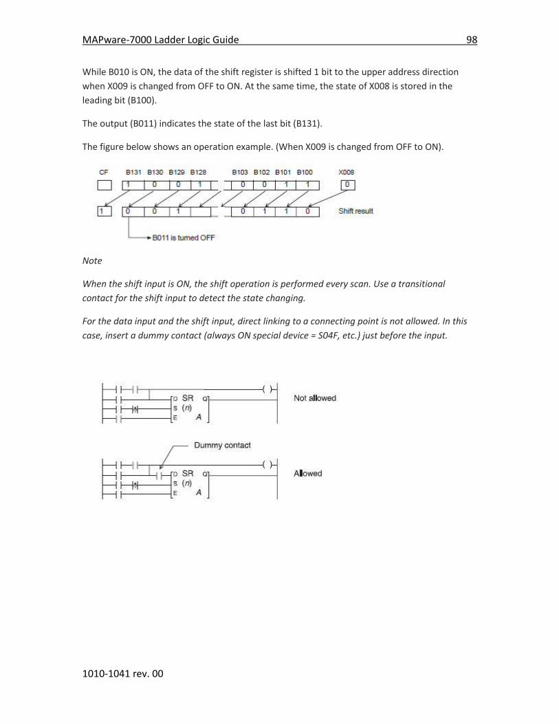
MAPware-7000 Ladder Logic Guide 98
1010-1041 rev. 00
While B010 is ON, the data of the shift register is shifted 1 bit to the upper address direction
when X009 is changed from OFF to ON. At the same time, the state of X008 is stored in the
leading bit (B100).
The output (B011) indicates the state of the last bit (B131).
The figure below shows an operation example. (When X009 is changed from OFF to ON).
Note
When the shift input is ON, the shift operation is performed every scan. Use a transitional
contact for the shift input to detect the state changing.
For the data input and the shift input, direct linking to a connecting point is not allowed. In this
case, insert a dummy contact (always ON special device = S04F, etc.) just before the input.
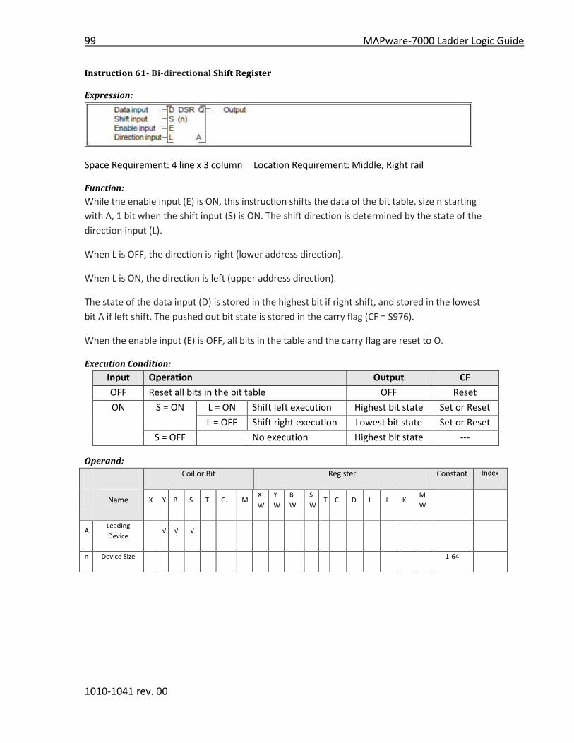
99 MAPware-7000 Ladder Logic Guide
1010-1041 rev. 00
Instruction 61- Bi-directional Shift Register
Expression:
Space Requirement: 4 line x 3 column Location Requirement: Middle, Right rail
Function:
While the enable input (E) is ON, this instruction shifts the data of the bit table, size n starting
with A, 1 bit when the shift input (S) is ON. The shift direction is determined by the state of the
direction input (L).
When L is OFF, the direction is right (lower address direction).
When L is ON, the direction is left (upper address direction).
The state of the data input (D) is stored in the highest bit if right shift, and stored in the lowest
bit A if left shift. The pushed out bit state is stored in the carry flag (CF = S976).
When the enable input (E) is OFF, all bits in the table and the carry flag are reset to O.
Execution Condition:
Input Operation Output CF
OFF Reset all bits in the bit table OFF Reset
ON S = ON L = ON Shift left execution Highest bit state Set or Reset
L = OFF Shift right execution Lowest bit state Set or Reset
S = OFF No execution Highest bit state ---
Operand:
Coil or Bit Register Constant Index
Name X Y B S T. C. M
X
W
Y
W
B
W
S
W T C D I J K
M
W
A Leading
Device √ √ √
n Device Size 1-64
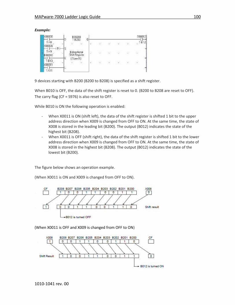
MAPware-7000 Ladder Logic Guide 100
1010-1041 rev. 00
Example:
9 devices starting with B200 (B200 to B208) is specified as a shift register.
When B010 is OFF, the data of the shift register is reset to 0. (B200 to B208 are reset to OFF).
The carry flag (CF = S976) is also reset to OFF.
While B010 is ON the following operation is enabled:
- When X0011 is ON (shift left), the data of the shift register is shifted 1 bit to the upper address direction when X009 is changed from OFF to ON. At the same time, the state of X008 is stored in the leading bit (B200). The output (B012) indicates the state of the highest bit (B208).
- When X0011 is OFF (shift right), the data of the shift register is shifted 1 bit to the lower address direction when X009 is changed from OFF to ON. At the same time, the state of X008 is stored in the highest bit (B208). The output (B012) indicates the state of the lowest bit (B200).
The figure below shows an operation example.
(When X0011 is ON and X009 is changed from OFF to ON).
(When X0011 is OFF and X009 is changed from OFF to ON)
101 MAPware-7000 Ladder Logic Guide
1010-1041 rev. 00
Note:
When the shift input is ON, the shift operation is performed every scan. Use a transitional
contact for the shift input to detect the state changing.
For the data input, the shift input and the enable input, direct linking to a connecting point is
not allowed. In this case, insert a dummy contact (always ON special device = S04F, etc.) just
before the input.

MAPware-7000 Ladder Logic Guide 102
1010-1041 rev. 00
Instruction 62- 1 bit rotate right
Expression:
Space Requirement: 1 line x 3 column Location Requirement: Middle, Right rail
Function:
When the input is ON, the data of register A is rotated 1 bit to the right (LSB direction). The
pushed out bit state is stored in the left most bit (MSB) and in the carry flag (CF = S976). After
the operation, if the right most bit (LSB) is ON, the output is turned ON.
Execution Condition:
Input Operation Output CF
OFF No execution OFF ---
ON Execution When LSB = 1 ON Set or Reset
When LSB = 0 OFF Set or Reset
Operand:
Coil or Bit Register Constant Index
Name X Y B S T. C. M
X
W
Y
W
B
W
S
W T C D I J K
M
W
A Operation
Data √ √ √ √ √ √ √ √ √ √
Example:
When X007 is changed from OFF to ON, the data of BW15 is rotated 1 bit to the right.
The figure below shows an operation example.

103 MAPware-7000 Ladder Logic Guide
1010-1041 rev. 00
Instruction 63- 1 bit rotate left
Expression:
Space Requirement: 1 line x 3 column Location Requirement: Middle, Right rail
Function:
When the input is ON, the data of register A is rotated 1 bit to the left (MSB direction). The
pushed out bit state is stored in the right most bit (LSB) and in the carry flag (CF = S976). After
the operation, if the left most bit (MSB) is ON, the output is turned ON.
Execution Condition:
Input Operation Output CF
OFF No execution OFF ---
ON Execution When MSB = 1 ON Set or Reset
When MSB = 0 OFF Set or Reset
Operand:
Coil or Bit Register Constant Index
Name X Y B S T. C. M
X
W
Y
W
B
W
S
W T C D I J K
M
W
A Operation
Data √ √ √ √ √ √ √ √ √ √
Example:
When X008 is changed from OFF to ON, the data of BW15 is rotated 1 bit to the left.
The figure below shows an operation example.
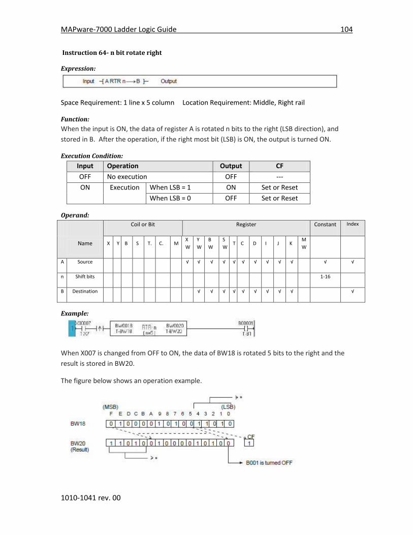
MAPware-7000 Ladder Logic Guide 104
1010-1041 rev. 00
Instruction 64- n bit rotate right
Expression:
Space Requirement: 1 line x 5 column Location Requirement: Middle, Right rail
Function:
When the input is ON, the data of register A is rotated n bits to the right (LSB direction), and
stored in B. After the operation, if the right most bit (LSB) is ON, the output is turned ON.
Execution Condition:
Input Operation Output CF
OFF No execution OFF ---
ON Execution When LSB = 1 ON Set or Reset
When LSB = 0 OFF Set or Reset
Operand:
Coil or Bit Register Constant Index
Name X Y B S T. C. M
X
W
Y
W
B
W
S
W T C D I J K
M
W
A Source √ √ √ √ √ √ √ √ √ √ √ √
n Shift bits 1-16
B Destination √ √ √ √ √ √ √ √ √ √
Example:
When X007 is changed from OFF to ON, the data of BW18 is rotated 5 bits to the right and the
result is stored in BW20.
The figure below shows an operation example.
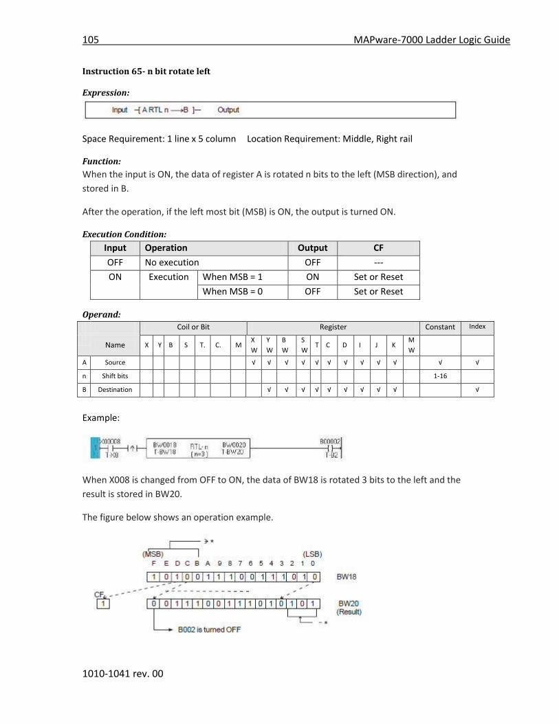
105 MAPware-7000 Ladder Logic Guide
1010-1041 rev. 00
Instruction 65- n bit rotate left
Expression:
Space Requirement: 1 line x 5 column Location Requirement: Middle, Right rail
Function:
When the input is ON, the data of register A is rotated n bits to the left (MSB direction), and
stored in B.
After the operation, if the left most bit (MSB) is ON, the output is turned ON.
Execution Condition:
Input Operation Output CF
OFF No execution OFF ---
ON Execution When MSB = 1 ON Set or Reset
When MSB = 0 OFF Set or Reset
Operand:
Coil or Bit Register Constant Index
Name X Y B S T. C. M
X
W
Y
W
B
W
S
W T C D I J K
M
W
A Source √ √ √ √ √ √ √ √ √ √ √ √
n Shift bits 1-16
B Destination √ √ √ √ √ √ √ √ √ √
Example:
When X008 is changed from OFF to ON, the data of BW18 is rotated 3 bits to the left and the
result is stored in BW20.
The figure below shows an operation example.
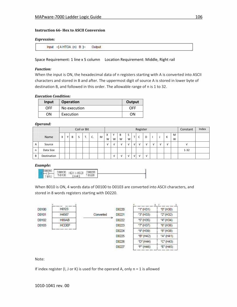
MAPware-7000 Ladder Logic Guide 106
1010-1041 rev. 00
Instruction 66- Hex to ASCII Conversion
Expression:
Space Requirement: 1 line x 5 column Location Requirement: Middle, Right rail
Function:
When the input is ON, the hexadecimal data of n registers starting with A is converted into ASCII
characters and stored in B and after. The uppermost digit of source A is stored in lower byte of
destination B, and followed in this order. The allowable range of n is 1 to 32.
Execution Condition:
Input Operation Output
OFF No execution OFF
ON Execution ON
Operand:
Coil or Bit Register Constant Index
Name X Y B S T. C. M
X
W
Y
W
B
W
S
W T C D I J K
M
W
A Source √ √ √ √ √ √ √ √ √ √ √
n Data Size 1-32
B Destination √ √ √ √ √ √
Example:
When B010 is ON, 4 words data of D0100 to D0103 are converted into ASCII characters, and
stored in 8 words registers starting with D0220.
Note:
If index register (I, J or K) is used for the operand A, only n = 1 is allowed
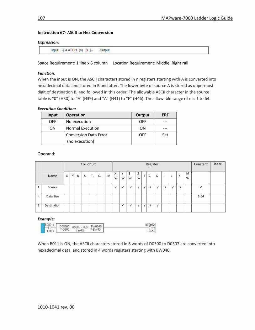
107 MAPware-7000 Ladder Logic Guide
1010-1041 rev. 00
Instruction 67- ASCII to Hex Conversion
Expression:
Space Requirement: 1 line x 5 column Location Requirement: Middle, Right rail
Function:
When the input is ON, the ASCII characters stored in n registers starting with A is converted into
hexadecimal data and stored in B and after. The lower byte of source A is stored as uppermost
digit of destination B, and followed in this order. The allowable ASCII character in the source
table is “0” (H30) to “9” (H39) and “A” (H41) to “F” (H46). The allowable range of n is 1 to 64.
Execution Condition:
Input Operation Output ERF
OFF No execution OFF ---
ON Normal Execution ON ---
Conversion Data Error
(no execution)
OFF Set
Operand:
Coil or Bit Register Constant Index
Name X Y B S T. C. M
X
W
Y
W
B
W
S
W T C D I J K
M
W
A Source √ √ √ √ √ √ √ √ √ √ √
n Data Size 1-64
B Destination √ √ √ √ √ √
Example:
When B011 is ON, the ASCII characters stored in 8 words of D0300 to D0307 are converted into
hexadecimal data, and stored in 4 words registers starting with BW040.
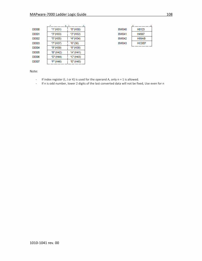
MAPware-7000 Ladder Logic Guide 108
1010-1041 rev. 00
Note:
- If index register (I, J or K) is used for the operand A, only n = 1 is allowed. - If n is odd number, lower 2 digits of the last converted data will not be fixed, Use even for n

109 MAPware-7000 Ladder Logic Guide
1010-1041 rev. 00
Instruction 68- Absolute Value
Expression:
Space Requirement: 1 line x 5 column Location Requirement: Middle, Right rail
Function:
When the input is ON, this instruction finds the absolute value of operand A, and stores it in B.
Execution Condition:
Input Operation Output
OFF No execution OFF
ON Execution ON
Operand:
Coil or Bit Register Constant Index
Name X Y B S T. C. M
X
W
Y
W
B
W
S
W T C D I J K
M
W
A Source √ √ √ √ √ √ √ √ √ √
B Destination √ √ √ √ √ √ √ √ √
Example:
When X006 is ON, the absolute value of BW38 is stored in D0121.
For example, if BW38 is -12000, the absolute value 12000 is stored in D0121.
Note:
- The data range of A is -32768 to 32767. If the data of A is -32768, then 32767 is stored in B.
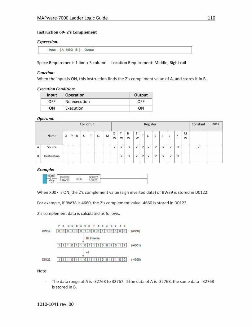
MAPware-7000 Ladder Logic Guide 110
1010-1041 rev. 00
Instruction 69- 2’s Complement
Expression:
Space Requirement: 1 line x 5 column Location Requirement: Middle, Right rail
Function:
When the input is ON, this instruction finds the 2’s compliment value of A, and stores it in B.
Execution Condition:
Input Operation Output
OFF No execution OFF
ON Execution ON
Operand:
Coil or Bit Register Constant Index
Name X Y B S T. C. M
X
W
Y
W
B
W
S
W T C D I J K
M
W
A Source √ √ √ √ √ √ √ √ √ √ √
B Destination √ √ √ √ √ √ √ √ √
Example:
When X007 is ON, the 2’s complement value (sign inverted data) of BW39 is stored in D0122.
For example, if BW38 is 4660, the 2’s complement value -4660 is stored in D0122.
2’s complement data is calculated as follows.
Note:
- The data range of A is -32768 to 32767. If the data of A is -32768, the same data -32768 is stored in B.

111 MAPware-7000 Ladder Logic Guide
1010-1041 rev. 00
Instruction 70- Double-word 2’s Complement
Expression:
Space Requirement: 1 line x 5 column Location Requirement: Middle, Right rail
Function:
When the input is ON, this instruction finds the 2’s complement value of double-word data
A+1×A, and stores it in B+1×B..
Execution Condition:
Input Operation Output
OFF No execution OFF
ON Execution ON
Operand:
Coil or Bit Register Constant Index
Name X Y B S T. C. M
X
W
Y
W
B
W
S
W T C D I J K
M
W
A Source √ √ √ √ √ √ √ √
B Destination √ √ √ √ √ √
Example:
When X007 is ON, the 2’s complement value (sign inverted data) of double-word register
BW41×BW40 is stored in double-word register D0051×D0050.
For example, if BW41×BW40 is -1234567890, the 2’s complement value 1234567890 is stored in
D0051×D0050.
Note:
- The data range of A+1× A is -2147483648 to 2147483647. If the data of A+1× A is -2147483648, the same data -2147483648 is stored in B+1× B.

MAPware-7000 Ladder Logic Guide 112
1010-1041 rev. 00
Instruction 71- 7 Segment Decode
Expression:
Space Requirement: 1 line x 5 column Location Requirement: Middle, Right rail
Function:
When the input is ON, this instruction converts the lower 4 bits data of A into the 7 segment
code, and stores it in B. The 7 segment code is normally used for a numeric display LED.
Execution Condition:
Input Operation Output
OFF No execution OFF
ON Execution ON
Operand:
Coil or Bit Register Constant Index
Name X Y B S T. C. M
X
W
Y
W
B
W
S
W T C D I J K
M
W
A Source √ √ √ √ √ √ √ √ √ √ √
B Destination √ √ √ √ √ √ √ √ √
Example:
When X000 is ON, the lower 4 bits data of BW15 is converted into the 7 segment code, and the
result is stored in lower 8 bits of BW10. 0 is stored in upper 8 bits of BW10.
For example, if BW15 is H0009, the corresponding 7 segment code H006F is stored in BW1.
The 7 segment code conversion table is shown on the next page.

113 MAPware-7000 Ladder Logic Guide
1010-1041 rev. 00
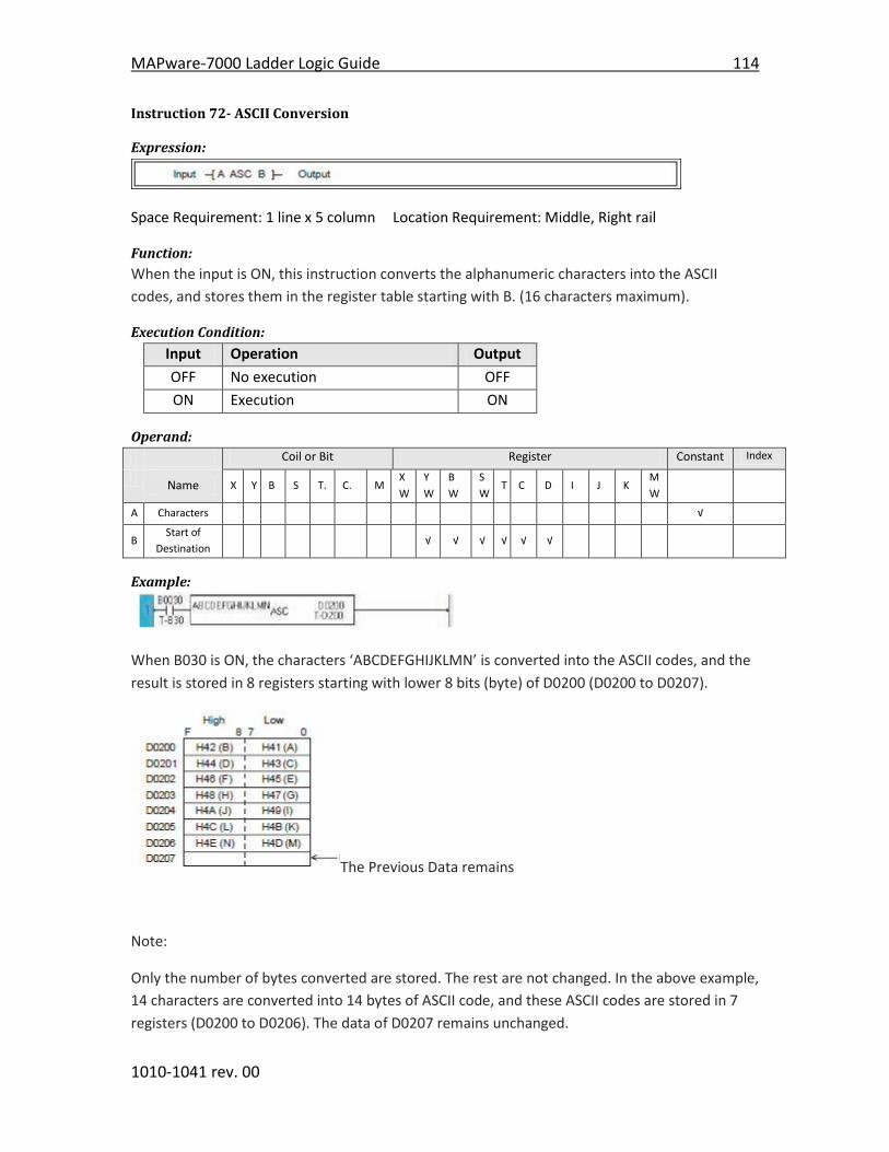
MAPware-7000 Ladder Logic Guide 114
1010-1041 rev. 00
Instruction 72- ASCII Conversion
Expression:
Space Requirement: 1 line x 5 column Location Requirement: Middle, Right rail
Function:
When the input is ON, this instruction converts the alphanumeric characters into the ASCII
codes, and stores them in the register table starting with B. (16 characters maximum).
Execution Condition:
Input Operation Output
OFF No execution OFF
ON Execution ON
Operand:
Coil or Bit Register Constant Index
Name X Y B S T. C. M
X
W
Y
W
B
W
S
W T C D I J K
M
W
A Characters √
B Start of
Destination √ √ √ √ √ √
Example:
When B030 is ON, the characters ‘ABCDEFGHIJKLMN’ is converted into the ASCII codes, and the
result is stored in 8 registers starting with lower 8 bits (byte) of D0200 (D0200 to D0207).
The Previous Data remains
Note:
Only the number of bytes converted are stored. The rest are not changed. In the above example,
14 characters are converted into 14 bytes of ASCII code, and these ASCII codes are stored in 7
registers (D0200 to D0206). The data of D0207 remains unchanged.

115 MAPware-7000 Ladder Logic Guide
1010-1041 rev. 00
Instruction 73- Binary Conversion
Expression:
Space Requirement: 1 line x 5 column Location Requirement: Middle, Right rail
Function:
When the input is ON, this instruction converts the 4 digits of BCD data of A into binary, and
stores in B. If any digit of A contains non-BCD code (other than H0 through H9), the conversion is
not executed and the instruction error flag (ERF = S1010) is set to ON.
Execution Condition:
Input Operation Output ERF
OFF No execution OFF ---
ON Normal Execution ON ---
BCD data error OFF Set
Operand:
Coil or Bit Register Constant Index
Name X Y B S T. C. M
X
W
Y
W
B
W
S
W T C D I J K
M
W
A Source (BCD) √ √ √ √ √ √ √ √ √ √ H0000-
9999
B Destination
(binary) √ √ √ √ √ √ √ √ √
Example:
When B017 is ON, the BCD data of BW28 is converted into binary data, and the result is stored
in D0127.
For example, if BW28 is H1234, the binary data 1234 is stored in D0127.
Note:
If any digit of operand A contains non-BCD data, e.g. H13A6, the conversion is not executed and
the instruction error flag (ERF = S1010) is set to ON.

MAPware-7000 Ladder Logic Guide 116
1010-1041 rev. 00
Instruction 74- BCD Conversion
Expression:
Space Requirement: 1 line x 5 column Location Requirement: Middle, Right rail
Function:
When the input is ON, this instruction converts the binary data of A into BCD, and stores in B. If
the data of A is not in the range of 0 to 9999, the conversion is not executed and the instruction
error flag (ERF = S1010) is set to ON.
Execution Condition:
Input Operation Output ERF
OFF No execution OFF ---
ON Normal Execution ON ---
BCD data error OFF Set
Operand:
Coil or Bit Register Constant Index
Name X Y B S T. C. M
X
W
Y
W
B
W
S
W T C D I J K
M
W
A Source
(binary) √ √ √ √ √ √ √ √ √ √ 0-9999
B Destination
(BCD) √ √ √ √ √ √ √ √ √
Example:
When B019 is ON, the data of D0211 is converted into 4-digit BCD, and the result is stored in
BW22.
For example, if D0211 is 5432, the BCD data H5432 is stored in BW22.
Note:
If the data of A is smaller than 0 or greater than 9999, the conversion is not executed and the
instruction error flag (ERF = S1010) is set to ON.
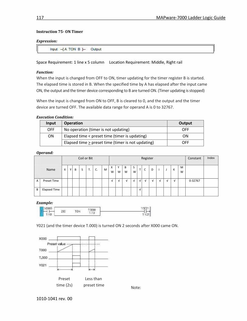
117 MAPware-7000 Ladder Logic Guide
1010-1041 rev. 00
Instruction 75- ON Timer
Expression:
Space Requirement: 1 line x 5 column Location Requirement: Middle, Right rail
Function:
When the input is changed from OFF to ON, timer updating for the timer register B is started.
The elapsed time is stored in B. When the specified time by A has elapsed after the input came
ON, the output and the timer device corresponding to B are turned ON. (Timer updating is stopped)
When the input is changed from ON to OFF, B is cleared to 0, and the output and the timer
device are turned OFF. The available data range for operand A is 0 to 32767.
Execution Condition:
Input Operation Output
OFF No operation (timer is not updating) OFF
ON Elapsed time < preset time (timer is updating) ON
Elapsed time > preset time (timer is not updating) OFF
Operand:
Coil or Bit Register Constant Index
Name X Y B S T. C. M
X
W
Y
W
B
W
S
W T C D I J K
M
W
A Preset Time √ √ √ √ √ √ √ √ √ √ 0-32767
B Elapsed Time √
Example:
Y021 (and the timer device T.000) is turned ON 2 seconds after X000 came ON.
Preset Less than
time (2s) preset time
Note:

MAPware-7000 Ladder Logic Guide 118
1010-1041 rev. 00
Time is set in 10 ms units for;
RMP10: T000 to T060 (0 to 327.67 s)
Time is set in 100 ms units for;
RMP10: T061 to T190 (0 to 3276.7 s)
Time is set in 1 s units for;
RMP10: T191 to T255 (0 to 32767 s)
Note:
Multiple timer instructions (TON, TOF or TSS) with the same timer register are not allowed.

119 MAPware-7000 Ladder Logic Guide
1010-1041 rev. 00
Instruction 76- OFF Timer
Expression:
Space Requirement: 1 line x 5 column Location Requirement: Middle, Right rail
Function:
When the input is changed from OFF to ON, the output and the timer device corresponding to
the timer register B are set to ON. When the input is changed from ON to OFF, timer updating
for B is started. The elapsed time is stored in B. When the specified time by A has elapsed after
the input came OFF, the output and the timer device are turned OFF. (Timer updating is stopped)
The available data range for operand A is 0 to 32767.
Execution Condition:
Input Operation Output
OFF Elapsed time < preset time (timer is updating) ON
Elapsed time > preset time (timer is not updating) OFF
ON No operation (timer is not updating) ON
Operand:
Coil or Bit Register Constant Index
Name X Y B S T. C. M
X
W
Y
W
B
W
S
W T C D I J K
M
W
A Preset Time √ √ √ √ √ √ √ √ √ √ 0-32767
B Elapsed Time √
Example:
Y021 (and the timer device T.002) is turned OFF 1 second after X000 came ON.
Preset Less than
time (1s) preset time

MAPware-7000 Ladder Logic Guide 120
1010-1041 rev. 00
Note:
Time is set in 10 ms units for;
RMP10: T000 to T060 (0 to 327.67 s)
Time is set in 100 ms units for;
RMP10: T061 to T190 (0 to 3276.7 s)
Time is set in 1 s units for;
RMP10: T191 to T255 (0 to 32767 s)
Note:
Multiple timer instructions (TON, TOF or TSS)
with the same timer register are not allowed.
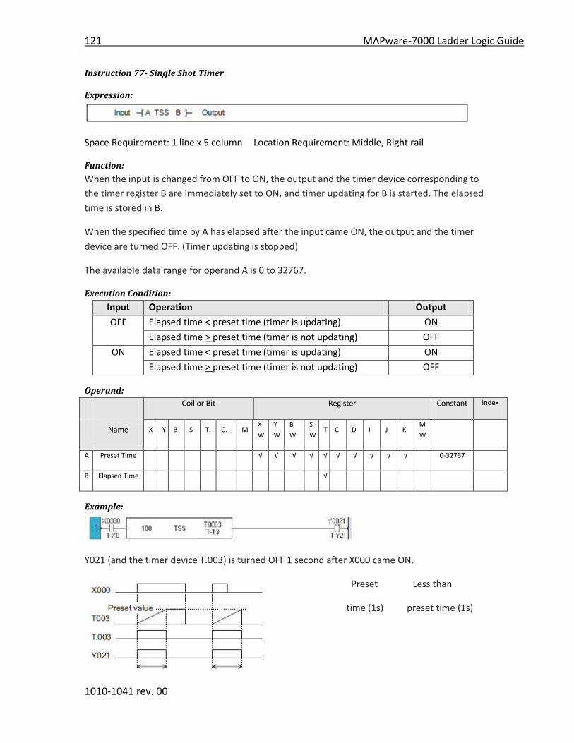
121 MAPware-7000 Ladder Logic Guide
1010-1041 rev. 00
Instruction 77- Single Shot Timer
Expression:
Space Requirement: 1 line x 5 column Location Requirement: Middle, Right rail
Function:
When the input is changed from OFF to ON, the output and the timer device corresponding to
the timer register B are immediately set to ON, and timer updating for B is started. The elapsed
time is stored in B.
When the specified time by A has elapsed after the input came ON, the output and the timer
device are turned OFF. (Timer updating is stopped)
The available data range for operand A is 0 to 32767.
Execution Condition:
Input Operation Output
OFF Elapsed time < preset time (timer is updating) ON
Elapsed time > preset time (timer is not updating) OFF
ON Elapsed time < preset time (timer is updating) ON
Elapsed time > preset time (timer is not updating) OFF
Operand:
Coil or Bit Register Constant Index
Name X Y B S T. C. M
X
W
Y
W
B
W
S
W T C D I J K
M
W
A Preset Time √ √ √ √ √ √ √ √ √ √ 0-32767
B Elapsed Time √
Example:
Y021 (and the timer device T.003) is turned OFF 1 second after X000 came ON.
Preset Less than
time (1s) preset time (1s)
MAPware-7000 Ladder Logic Guide 122
1010-1041 rev. 00
Note:
Time is set in 10 ms units for;
RMP10: T000 to T060 (0 to 327.67 s)
Time is set in 100 ms units for;
RMP10: T061 to T190 (0 to 3276.7 s)
Time is set in 1 s units for;
RMP10: T191 to T255 (0 to 32767 s)
Note:
Multiple timer instructions (TON, TOF or TSS) with the same timer register are not allowed.

123 MAPware-7000 Ladder Logic Guide
1010-1041 rev. 00
Instruction 78- Counter
Expression:
Space Requirement: 2 line x 3 column Location Requirement: Middle, Right rail
Function:
While the enable input is ON, this instruction counts the number of the count input changes
from OFF to ON. The count value is stored in the counter register B. When the count value
reaches the set value A, the output and the counter device corresponding to B are turned ON.
When the enable input comes OFF, B is cleared to 0 and the output and the counter device are
turned OFF.
The available data range for operand A is 0 to 65535.
Execution Condition:
Input Operation Output
OFF No operation (B is cleared to 0) OFF
ON Count value (B) < set value (A) OFF
Count value (B) > set value (A) ON
Operand:
Coil or Bit Register Constant Index
Name X Y B S T. C. M
X
W
Y
W
B
W
S
W T C D I J K
M
W
A Set Value √ √ √ √ √ √ √ √ √ √ 0-65535
B Count Value √
Example:
Y021 (and the timer device T.003) is turned OFF 1 second after X000 came ON.

MAPware-7000 Ladder Logic Guide 124
1010-1041 rev. 00
Note:
No transitional contact is required for the count
input. The count input rising edge is detected by
this instruction.
For the count input, direct linking to a
connecting point is not allowed. In this case,
insert a dummy contact (always ON = S04F, etc.)
just before the input.
Refer to Note of Shift register FUN 074.
Multiple counter instructions (CNT) with the
same counter register are not allowed.
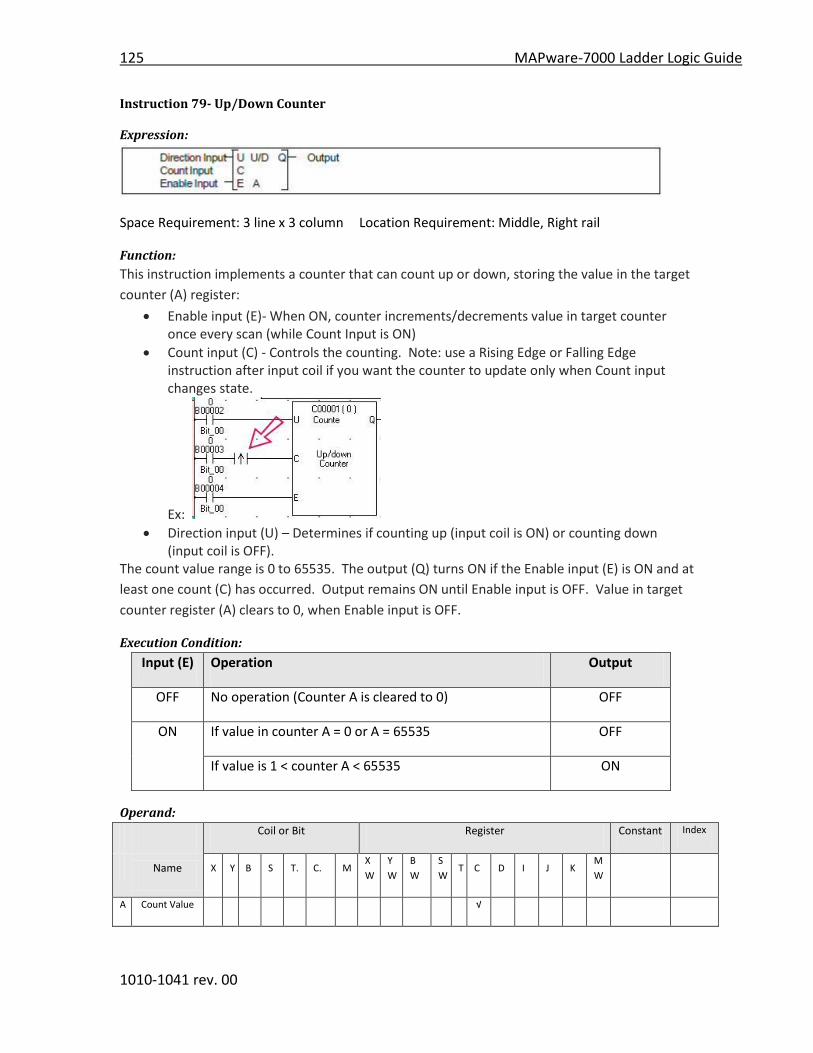
125 MAPware-7000 Ladder Logic Guide
1010-1041 rev. 00
Instruction 79- Up/Down Counter
Expression:
Space Requirement: 3 line x 3 column Location Requirement: Middle, Right rail
Function:
This instruction implements a counter that can count up or down, storing the value in the target
counter (A) register:
Enable input (E)- When ON, counter increments/decrements value in target counter once every scan (while Count Input is ON)
Count input (C) - Controls the counting. Note: use a Rising Edge or Falling Edge instruction after input coil if you want the counter to update only when Count input changes state.
Ex:
Direction input (U) – Determines if counting up (input coil is ON) or counting down (input coil is OFF).
The count value range is 0 to 65535. The output (Q) turns ON if the Enable input (E) is ON and at
least one count (C) has occurred. Output remains ON until Enable input is OFF. Value in target
counter register (A) clears to 0, when Enable input is OFF.
Execution Condition:
Input (E) Operation Output
OFF No operation (Counter A is cleared to 0) OFF
ON If value in counter A = 0 or A = 65535 OFF
If value is 1 < counter A < 65535 ON
Operand:
Coil or Bit Register Constant Index
Name X Y B S T. C. M
X
W
Y
W
B
W
S
W T C D I J K
M
W
A Count Value √

MAPware-7000 Ladder Logic Guide 126
1010-1041 rev. 00
Example:
Note:
The transitional contact is required for the count
input. Otherwise, counting is executed every
scan while X005 is ON in this example.
For the direction input and the count input,
direct linking to a connecting point is not
allowed.
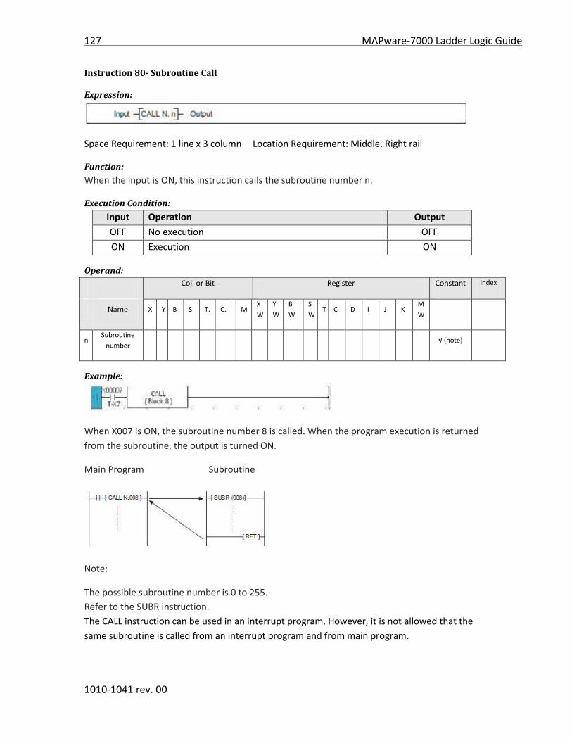
127 MAPware-7000 Ladder Logic Guide
1010-1041 rev. 00
Instruction 80- Subroutine Call
Expression:
Space Requirement: 1 line x 3 column Location Requirement: Middle, Right rail
Function:
When the input is ON, this instruction calls the subroutine number n.
Execution Condition:
Input Operation Output
OFF No execution OFF
ON Execution ON
Operand:
Coil or Bit Register Constant Index
Name X Y B S T. C. M
X
W
Y
W
B
W
S
W T C D I J K
M
W
n Subroutine
number √ (note)
Example:
When X007 is ON, the subroutine number 8 is called. When the program execution is returned
from the subroutine, the output is turned ON.
Main Program Subroutine
Note:
The possible subroutine number is 0 to 255.
Refer to the SUBR instruction.
The CALL instruction can be used in an interrupt program. However, it is not allowed that the
same subroutine is called from an interrupt program and from main program.

MAPware-7000 Ladder Logic Guide 128
1010-1041 rev. 00
Instruction 81- Subroutine Return
Expression:
Space Requirement: 1 line x 1 column Location Requirement: Middle, Right rail
Function:
This instruction indicates the end of a subroutine. When program execution is reached this
instruction, it is returned to the original CALL instruction.
Execution Condition:
Input Operation Output
--- Execution ---
Operand:
No operand is required.
Example:
When X007 is ON, the subroutine number 8 is called. When the program execution is returned
from the subroutine, the output is turned ON.
Main Program Subroutine
Note:
Refer to the SUBR instruction.
The RET instruction can be programmed only in the program type ‘Subroutine’.
The RET instruction must be connected directly to the left power rail.
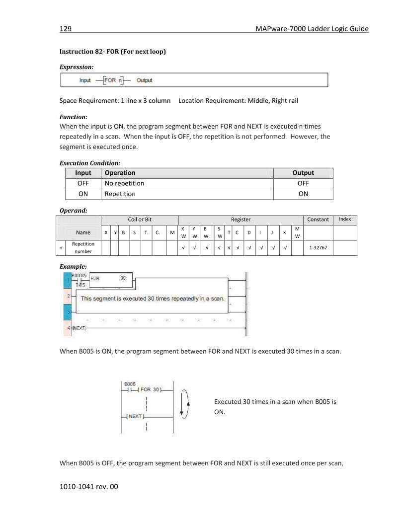
129 MAPware-7000 Ladder Logic Guide
1010-1041 rev. 00
Instruction 82- FOR (For next loop)
Expression:
Space Requirement: 1 line x 3 column Location Requirement: Middle, Right rail
Function:
When the input is ON, the program segment between FOR and NEXT is executed n times
repeatedly in a scan. When the input is OFF, the repetition is not performed. However, the
segment is executed once.
Execution Condition:
Input Operation Output
OFF No repetition OFF
ON Repetition ON
Operand:
Coil or Bit Register Constant Index
Name X Y B S T. C. M
X
W
Y
W
B
W
S
W T C D I J K
M
W
n Repetition
number √ √ √ √ √ √ √ √ √ √ 1-32767
Example:
When B005 is ON, the program segment between FOR and NEXT is executed 30 times in a scan.
Executed 30 times in a scan when B005 is
ON.
When B005 is OFF, the program segment between FOR and NEXT is still executed once per scan.
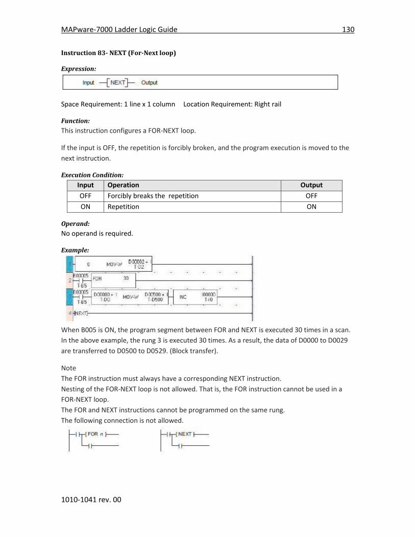
MAPware-7000 Ladder Logic Guide 130
1010-1041 rev. 00
Instruction 83- NEXT (For-Next loop)
Expression:
Space Requirement: 1 line x 1 column Location Requirement: Right rail
Function:
This instruction configures a FOR-NEXT loop.
If the input is OFF, the repetition is forcibly broken, and the program execution is moved to the
next instruction.
Execution Condition:
Input Operation Output
OFF Forcibly breaks the repetition OFF
ON Repetition ON
Operand:
No operand is required.
Example:
When B005 is ON, the program segment between FOR and NEXT is executed 30 times in a scan.
In the above example, the rung 3 is executed 30 times. As a result, the data of D0000 to D0029
are transferred to D0500 to D0529. (Block transfer).
Note
The FOR instruction must always have a corresponding NEXT instruction.
Nesting of the FOR-NEXT loop is not allowed. That is, the FOR instruction cannot be used in a
FOR-NEXT loop.
The FOR and NEXT instructions cannot be programmed on the same rung.
The following connection is not allowed.

131 MAPware-7000 Ladder Logic Guide
1010-1041 rev. 00
Instruction 84- Master Control Set/Reset
Expression:
Space Requirement: 1 line x 1 column Location Requirement: Right rail
Function:
When the MCS input is ON, ordinary operation is performed. When the MCS input is OFF, the
state of left power rail between MCS and MCR is turned OFF.
Execution Condition:
MCS
Input
Operation Output
OFF Sets OFF the left power rail until MCR ---
ON Ordinary operation ---
Operand:
No operand is required.
Example:
When X000 is OFF, Y021 and Y022 are turned OFF regardless of the states of X001 and X002.
Equivalent circuit:
Note
MCS and MCR must be used as a pair.
Nesting is not allowed.
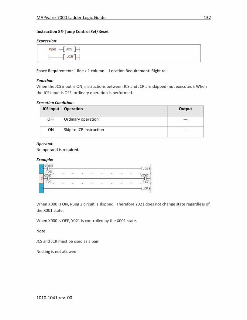
MAPware-7000 Ladder Logic Guide 132
1010-1041 rev. 00
Instruction 85- Jump Control Set/Reset
Expression:
Space Requirement: 1 line x 1 column Location Requirement: Right rail
Function:
When the JCS input is ON, instructions between JCS and JCR are skipped (not executed). When
the JCS input is OFF, ordinary operation is performed.
Execution Condition:
JCS Input Operation Output
OFF Ordinary operation ---
ON Skip to JCR instruction ---
Operand:
No operand is required.
Example:
When X000 is ON, Rung 2 circuit is skipped. Therefore Y021 does not change state regardless of
the X001 state.
When X000 is OFF, Y021 is controlled by the X001 state.
Note
JCS and JCR must be used as a pair.
Nesting is not allowed

133 MAPware-7000 Ladder Logic Guide
1010-1041 rev. 00
Instruction 86- Enable Interrupt
Expression:
Space Requirement: 1 line x 1 column Location Requirement: Middle, Right rail
Function:
When the input is ON, this instruction allows the execution of user designated interrupt
operations (i.e. timer interrupt and I/O interrupt programs) that may have been temporarily
disabled using the Disable Interrupt function.
Execution Condition:
Input Operation Output
OFF No execution OFF
ON Execution ON
Operand:
No operand is required.
Example:
In the above example, the DI instruction disables all Timer and I/O interrupts. Then the EI
instruction enables the interrupts again. As a result, Rung 2 instructions are executed without
possible interrupts disrupting the process.
Note
- Refer to the Disable Interrupt (DI) instruction. - If an interrupt request occurs when the interrupt is disabled, the interrupt is kept
waiting and it will be executed just after the EI instruction is executed. - The Enable Interrupt (EI) instruction can be used only in the main program

MAPware-7000 Ladder Logic Guide 134
1010-1041 rev. 00
Instruction 87- Disable Interrupt
Expression:
Space Requirement: 1 line x 1 column Location Requirement: Middle, Right rail
Function:
When the input is ON, this instruction disables the execution of user designated interrupt
operation, i.e. timer interrupt program and I/O interrupt programs.
Execution Condition:
Input Operation Output
OFF No execution OFF
ON Execution ON
Operand:
No operand is required.
Example:
In the above example, the interrupt is disabled when B000 is ON, and it is enabled when B000 is
OFF.
Note
- Refer to the Enable Interrupt (EI) instruction. - If an interrupt request occurs when the interrupt is disabled, the interrupt is kept
waiting and it will be executed just after the EI instruction is executed. - The Disable Interrupt (DI) instruction can be used only in the main program.

135 MAPware-7000 Ladder Logic Guide
1010-1041 rev. 00
Instruction 88- Watchdog timer reset
Expression:
Space Requirement: 1 line x 3 column Location Requirement: Middle, Right rail
Function:
When the input is ON, this instruction extends the watchdog timer reset time. A watchdog
timer is a timer that runs in the background. If the timer reaches its preset timeout value, then
it forces a reinitialization of the HMC7000. This is a safety feature that forces the unit back to a
known state in case something unexpected happens. Therefore, under normal conditions, the
watchdog timer would never time out before it was reset by the HMC7000. However, you may
have an unusually long ladder logic program or a subroutine that causes the scan time to exceed
200 msec. This instruction can be used to extend the watchdog timeout by multiple of 1msec.
(i.e. if n = 1 => 201ms; if n = 100 => 300ms).
Execution Condition:
Input Operation Output
OFF No execution OFF
ON Execution ON
Operand:
Coil or Bit Register Constant Index
Name X Y B S T. C. M
X
W
Y
W
B
W
S
W T C D I J K
M
W
n Extend time 1-100
Example:
When B020 is ON, the scan time detection time is extended by 10 msec. (for a total of 210
msec).
Note
- The operand n specifies the extended time. - The normal watchdog timeout is 200 ms

MAPware-7000 Ladder Logic Guide 136
1010-1041 rev. 00
Instruction 89- Step Sequence Initialize
Expression:
Space Requirement: 1 line x 3 column Location Requirement: Middle
Function:
When the input is ON, n devices starting with Operand A are reset to OFF, and A is set to ON.
This instruction is used to initialize a series of step sequences. The step sequence is useful to
describe a sequential operation.
Execution Condition:
Input Operation Output
OFF No execution OFF
ON Execution at the rising edge of the input ON
Operand:
Coil or Bit Register Constant Index
Name X Y B S T. C. M
X
W
Y
W
B
W
S
W T C D I J K
M
W
n Size of Step
Sequence 1-64
A Start Device √
Example:
When B020 changes from OFF to ON, B400 is set to ON and the next 9 devices (B401 to B409)
are reset to OFF.
This instruction initializes a series of step sequence, 10 devices starting with B400.
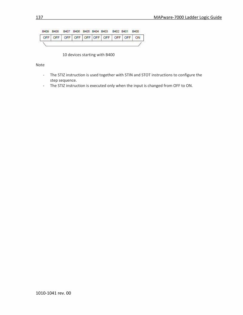
137 MAPware-7000 Ladder Logic Guide
1010-1041 rev. 00
10 devices starting with B400
Note
- The STIZ instruction is used together with STIN and STOT instructions to configure the step sequence.
- The STIZ instruction is executed only when the input is changed from OFF to ON.

MAPware-7000 Ladder Logic Guide 138
1010-1041 rev. 00
Instruction 90- Step Sequence Input
Expression:
Space Requirement: 1 line x 3 column Location Requirement: Middle
Function:
When the input is ON and the device A is ON; the output is set to ON.
Execution Condition:
Input Operation Output
OFF No execution OFF
ON When A is ON ON
When A is OFF OFF
Operand:
Coil or Bit Register Constant Index
Name X Y B S T. C. M
X
W
Y
W
B
W
S
W T C D I J K
M
W
A Step Device √
Example:
The following sequential operation is performed.
When B020 is changed from OFF to ON, B400 is set to ON and subsequent 9 devices (B401 to
B409) are reset to OFF.
When X004 comes ON, B400 is reset to OFF and B401 is set to ON.
When both X005 and B022 are ON, B401 is reset to OFF and B402 is set to ON.

139 MAPware-7000 Ladder Logic Guide
1010-1041 rev. 00
Instruction 91- Step Sequence Output
Expression:
Space Requirement: 1 line x 3 column Location Requirement: Middle
Function:
When the input is ON, the device A is set to ON and the devices of STIN instructions on the same
rung are reset to OFF.
Execution Condition:
Input Operation Output
OFF No execution ---
ON Execution ---
Operand:
Coil or Bit Register Constant Index
Name X Y B S T. C. M
X
W
Y
W
B
W
S
W T C D I J K
M
W
A Step Device √
Example:
See example on STIN instruction.
Note:
- The STIZ, STIN and STOT instructions are used together to configure the step sequence. - Two or more STOT instructions can be placed on one rung to perform simultaneous
sequences.
- Two or more STIN instructions can be placed on one rung in parallel or in series to perform loop of sequences. (Max. 11 STIN instructions on one rung)
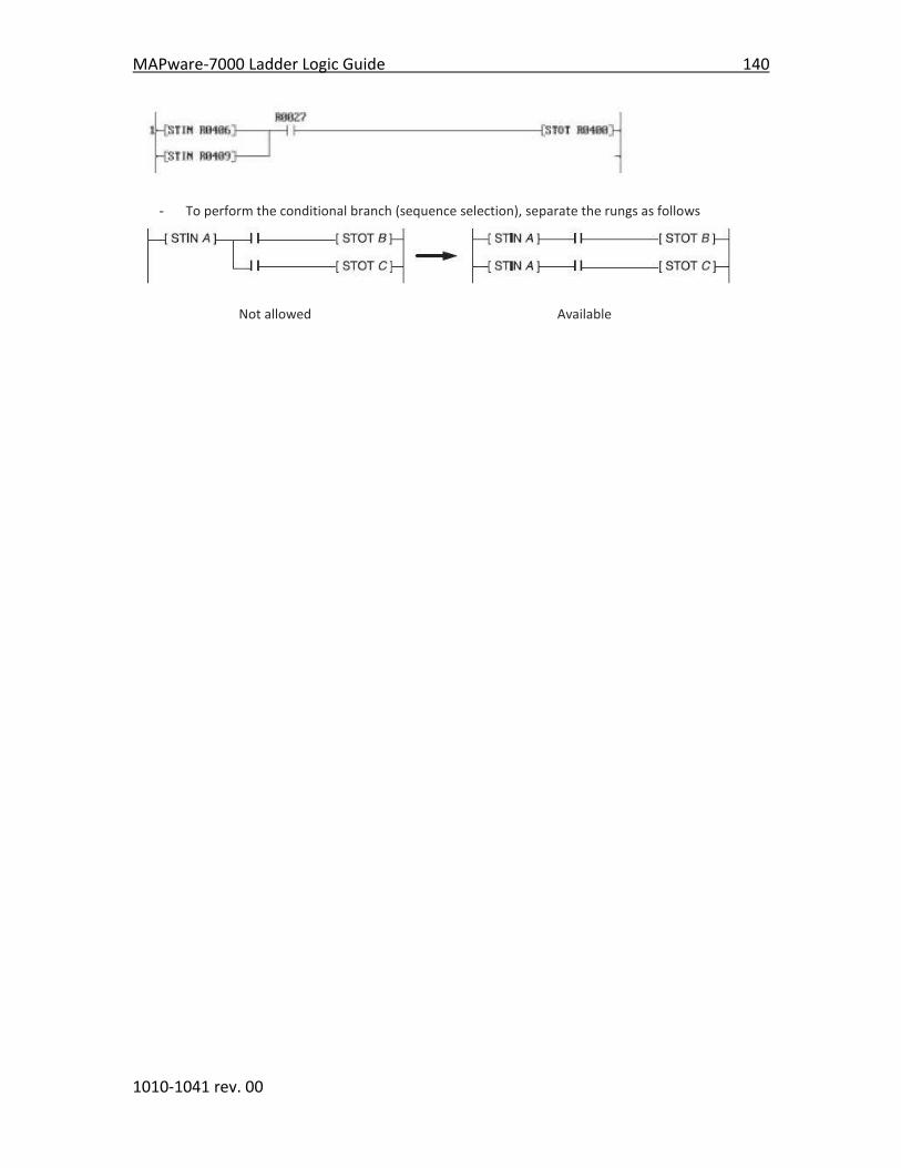
MAPware-7000 Ladder Logic Guide 140
1010-1041 rev. 00
- To perform the conditional branch (sequence selection), separate the rungs as follows
Not allowed Available

141 MAPware-7000 Ladder Logic Guide
1010-1041 rev. 00
Instruction 92- Moving Average
Expression:
Space Requirement: 1 line x 6 column Location Requirement: Middle, Right rail
Function:
When the input is ON, this instruction calculates the average value of the last (n) scanned values
in register A, and stores the average in register C. The number of scans (n) allowed is 1 to 64.
Register B is the start of the data table, (where scanned values are stored). Finally, Register C+1
is used as a pointer to the data table.
This instruction is primarily used for filtering analog input signals.
Execution Condition:
Input Operation Output
OFF No execution OFF
ON Execution ON
Operand:
Coil or Bit Register Constant Index
Name X Y B S T. C. M
X
W
Y
W
B
W
S
W T C D I J K
M
W
A Input Data √ √ √ √ √ √ √ √ √ √ √
n Input Data 1-64
B Start of
Table √ √ √ √ √ √
C Output Data √ √ √ √ √ √ √ √ √
Example:
Register XW04 (A) is read during every scan of the ladder logic. Number of scans (n) is set to 5.
The start of the data table (B) is D0900. Therefore, registers D0900-D0904 are used to store the
values read from XW04. D0010 (C) is used to store the calculated average and D0011 (C+1) is
used by this instruction as a pointer:

MAPware-7000 Ladder Logic Guide 142
1010-1041 rev. 00

143 MAPware-7000 Ladder Logic Guide
1010-1041 rev. 00
Instruction 93- Digital Filter
Expression:
Space Requirement: 1 line x 6 column Location Requirement: Middle, Right rail
Function:
When the input is ON, this instruction calculates the following formula to perform digital
filtering for input data A, using filter constant B, and stores the result in C.
Yn = (1 - FL) * Xn + (FL * Yn-1) where
Xn is the input data specified by A
FL is the filter constant; 1/10000 of value B (data range: 0 to 9999)
Yn is the computed result, stored in C
Yn-1 is result from the last scan
C+1 is used for internal data computations
This instruction is used for filtering analog input signals.
Execution Condition:
Input Operation Output
OFF No execution OFF
ON Execution (PLC7000 Series is limited within range of 0
to 9999).
ON
Operand:
Coil or Bit Register Constant Index
Name X Y B S T. C. M
X
W
Y
W
B
W
S
W T C D I J K
M
W
A Input Data √ √ √ √ √ √ √ √ √ √ √
B Filter
Constant √ √ √ √ √ √ √
C Output Data √ √ √ √ √ √
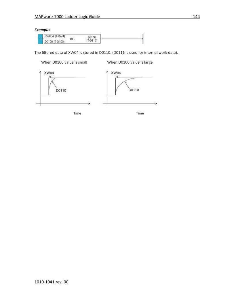
MAPware-7000 Ladder Logic Guide 144
1010-1041 rev. 00
Example:
The filtered data of XW04 is stored in D0110. (D0111 is used for internal work data).
When D0100 value is small When D0100 value is large
Time Time

145 MAPware-7000 Ladder Logic Guide
1010-1041 rev. 00
Instruction 94- PID1
Expression:
Space Requirement: 1 line x 6 column Location Requirement: Middle, Right rail
Function:
This function performs a PID (Proportional, Integral, and Derivative) calculation based upon
fourteen input values. Basically, a PID controller is used to monitor some measureable process
variable in a control system and determine how it varies (the “error” value) from a desired
setpoint. The PID controller then adjusts an input to the control system to minimize the error
value. The name is derived from the three basic mathematical functions that are performed in
order to derive the output:
Generally, the Proportional value tracks the present error, the Integral value tracks the
accumulation of past errors, and the Derivative value predicts future error based upon the
current rate of change. MAPware-7000 provides two PID controller instructions that are based
upon two different formulas.
PID1 is based upon the following formula:
--------P--------|------------------I-----------------|---------------------D-------------------|
M= Kp * (e-e-1) + INT ( | Kil | * e + Ir / |Kih| ) + INT [ (|Kdh| / |Kdl|) * (2P-1-P-P-2)]
where:
M= manipulation or control value
Kp = the proportional gain constant
e = deviation or error value
e-1 = deviation of prior computation
Kih = the integral gain constant (high limit value)
Kil = the integral gain constant (low limit value)
Kdh = the derivative gain constant (high limit value)
Kdl = the derivative gain constant (low limit value)
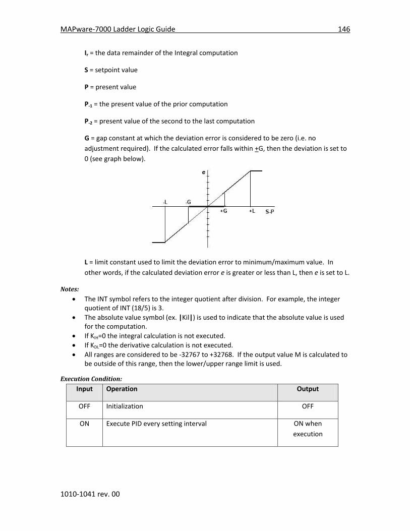
MAPware-7000 Ladder Logic Guide 146
1010-1041 rev. 00
Ir = the data remainder of the Integral computation
S = setpoint value
P = present value
P-1 = the present value of the prior computation
P-2 = present value of the second to the last computation
G = gap constant at which the deviation error is considered to be zero (i.e. no
adjustment required). If the calculated error falls within +G, then the deviation is set to
0 (see graph below).
L = limit constant used to limit the deviation error to minimum/maximum value. In
other words, if the calculated deviation error e is greater or less than L, then e is set to L.
Notes:
The INT symbol refers to the integer quotient after division. For example, the integer quotient of INT (18/5) is 3.
The absolute value symbol (ex. |Kil|) is used to indicate that the absolute value is used for the computation.
If KIH=0 the integral calculation is not executed.
If KDL=0 the derivative calculation is not executed.
All ranges are considered to be -32767 to +32768. If the output value M is calculated to be outside of this range, then the lower/upper range limit is used.
Execution Condition:
Input Operation Output
OFF Initialization OFF
ON Execute PID every setting interval ON when
execution
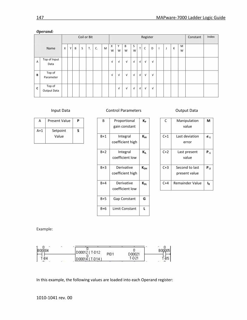
147 MAPware-7000 Ladder Logic Guide
1010-1041 rev. 00
Operand:
Coil or Bit Register Constant Index
Name X Y B S T. C. M
X
W
Y
W
B
W
S
W T C D I J K
M
W
A Top of Input
Data √ √ √ √ √ √ √
B Top of
Parameter √ √ √ √ √ √ √
C Top of
Output Data √ √ √ √ √ √
Input Data
A Present Value P
A+1 Setpoint
Value
S
Control Parameters
B Proportional
gain constant
KP
B+1 Integral
coefficient high
KIH
B+2 Integral
coefficient low
KIL
B+3 Derivative
coefficient high
KDH
B+4 Derivative
coefficient low
KDL
B+5 Gap Constant G
B+6 Limit Constant L
Output Data
C Manipulation
value
M
C+1 Last deviation
error
e-1
C+2 Last present
value
P-1
C+3 Second to last
present value
P-2
C+4 Remainder Value IR
Example:
In this example, the following values are loaded into each Operand register:

MAPware-7000 Ladder Logic Guide 148
1010-1041 rev. 00
Operand A
Offset Parameter Register Value
A Present Value D12 25
A+1 Setpoint Value D13 100
Operand B
Offset Parameter Register Value
B Proportional Coefficient D14 1
B+1 Integral Gain Constant High D15 4
B+2 Integral Gain Constant Low D16 10
B+3 Derivative Gain Constant Low D17 20
B+4 Derivative Gain Constant High D18 5
B+5 Gap Constant D19 0
B+6 Limit Constant D20 100
Operand C
Offset Parameter Register Value
C Manipulation Value D21 0
C+1 Last deviation error D22 78
C+2 Last Present Value D23 22
C+3 2nd to last Present Value D24 20
C+4 Remainder Value D25 0
When the normally open contact B4 is ON, the PID1 calculation is performed based upon the
formula given above and the values entered into the registers. The results are stored in the five
consecutive registers as specified by Operand C.
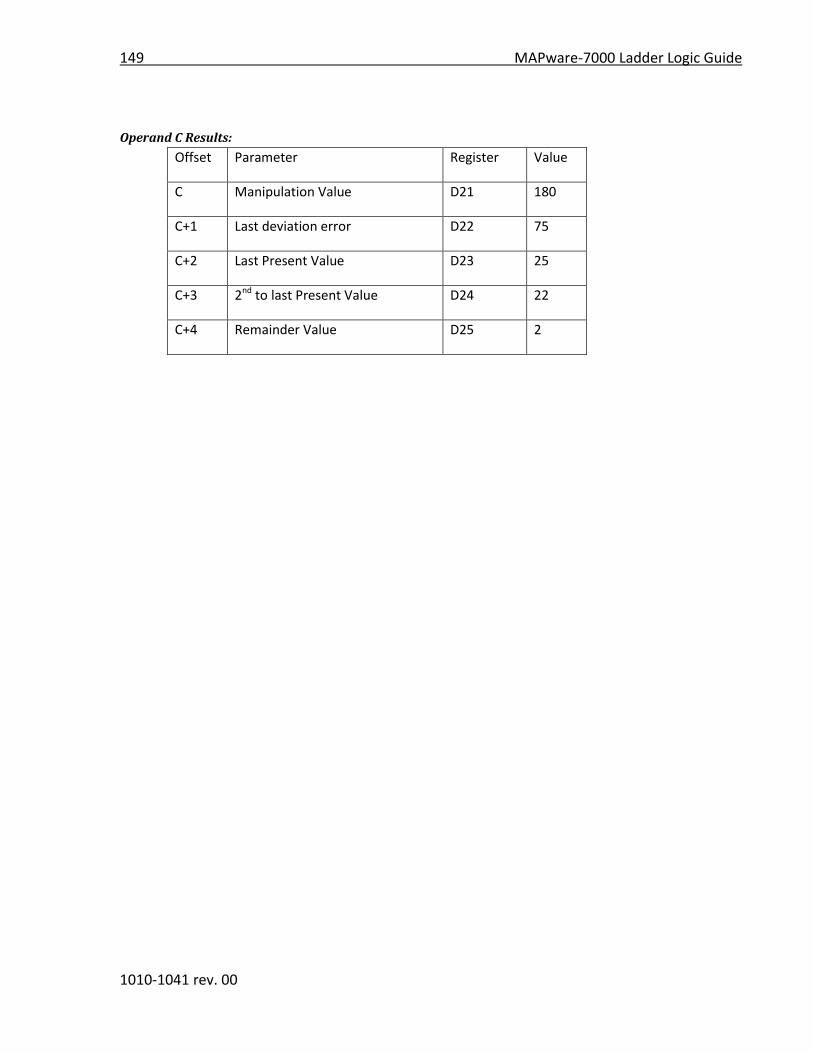
149 MAPware-7000 Ladder Logic Guide
1010-1041 rev. 00
Operand C Results:
Offset Parameter Register Value
C Manipulation Value D21 180
C+1 Last deviation error D22 75
C+2 Last Present Value D23 25
C+3 2nd to last Present Value D24 22
C+4 Remainder Value D25 2

MAPware-7000 Ladder Logic Guide 150
1010-1041 rev. 00
Instruction 95- PID4
Expression:
Space Requirement: 1 line x 6 column Location Requirement: Middle, Right rail
Function:
This function performs PID (Proportional, Integral, and Derivative) control which is a
fundamental method of feed-back control.
The basic idea behind the PID controller is to read a sensor, then compute the desired actuator
output by calculating proportional, integral, and derivative responses, then sum those three
components to derive an output value.
PID4 is based upon the following formula:
--P--|------------------I---------------------|---------D----------|
M= M-1 + KP * (e – e-1 + (e/TI) * (TS+1)) + KD(e – 2e-1 + e-2)
where:
M= manipulation value (range: 0 to 4095)
M-1= previous calculated manipulation value (range: 0 to 4095)
Kp = the proportional gain constant (range: -32768 to +32767)
e = deviation or error value;
if Action Type = reverse action then e=S-P;
if Action Type = forward action then e=P-S
A = Action Type (range: 0 for forward, 1 for reverse); this determines if the manipulation
value increases/decreases as the present value increases. For example, if you have an
electric heater, you would want the manipulation value to increase as temperature goes
down (i.e. reverse action so e=S-P). On the other hand, if you have a control valve used
to put cold air into a system, you would want the manipulation value to decrease as
temperature goes down (i.e. forward action so e=P-S).
e-1 = deviation of prior computation (range: -32768 to +32767)
e-2 = deviation of second to last computation (range: -32768 to +32767)
TI = integral time value (range: 0 to +32767)
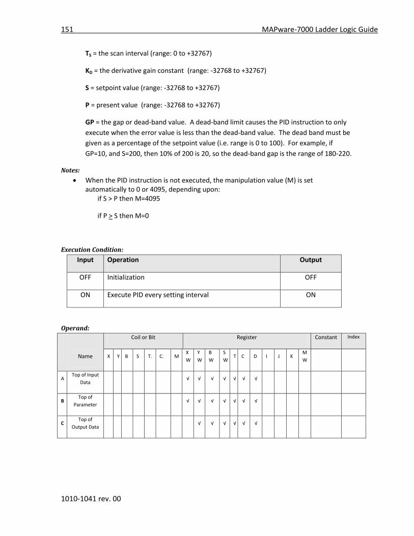
151 MAPware-7000 Ladder Logic Guide
1010-1041 rev. 00
TS = the scan interval (range: 0 to +32767)
KD = the derivative gain constant (range: -32768 to +32767)
S = setpoint value (range: -32768 to +32767)
P = present value (range: -32768 to +32767)
GP = the gap or dead-band value. A dead-band limit causes the PID instruction to only
execute when the error value is less than the dead-band value. The dead band must be
given as a percentage of the setpoint value (i.e. range is 0 to 100). For example, if
GP=10, and S=200, then 10% of 200 is 20, so the dead-band gap is the range of 180-220.
Notes:
When the PID instruction is not executed, the manipulation value (M) is set automatically to 0 or 4095, depending upon:
if S > P then M=4095
if P > S then M=0
Execution Condition:
Input Operation Output
OFF Initialization OFF
ON Execute PID every setting interval ON
Operand:
Coil or Bit Register Constant Index
Name X Y B S T. C. M
X
W
Y
W
B
W
S
W T C D I J K
M
W
A Top of Input
Data √ √ √ √ √ √ √
B Top of
Parameter √ √ √ √ √ √ √
C Top of
Output Data √ √ √ √ √ √

MAPware-7000 Ladder Logic Guide 152
1010-1041 rev. 00
Input Data
A Present Value P
A+1 Setpoint
Value
S
Control Parameters
B Proportional
gain constant
KP
B+1 Integral time TI
B+2 Derivative gain KD
B+3 Dead-band gap GP
B+4 Scan Interval TS
B+5 Action Type A
Output Data
C Manipulation
value
M
C+1 Last deviation
error
e-1
C+2 Second to last
deviation error
e-2
C+3 Prior
Manipulation
value
M-1
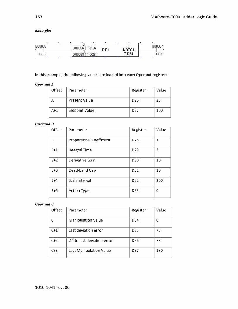
153 MAPware-7000 Ladder Logic Guide
1010-1041 rev. 00
Example:
In this example, the following values are loaded into each Operand register:
Operand A
Offset Parameter Register Value
A Present Value D26 25
A+1 Setpoint Value D27 100
Operand B
Offset Parameter Register Value
B Proportional Coefficient D28 1
B+1 Integral Time D29 3
B+2 Derivative Gain D30 10
B+3 Dead-band Gap D31 10
B+4 Scan Interval D32 200
B+5 Action Type D33 0
Operand C
Offset Parameter Register Value
C Manipulation Value D34 0
C+1 Last deviation error D35 75
C+2 2nd to last deviation error D36 78
C+3 Last Manipulation Value D37 180

MAPware-7000 Ladder Logic Guide 154
1010-1041 rev. 00
When the normally open contact B6 is ON, the PID4 calculation is performed based upon the
formula given above and the values entered into the registers. The results are stored in the four
consecutive registers as specified by Operand C.
Operand C Results:
Offset Parameter Register Value
C Manipulation Value D34 4095
C+1 Last deviation error D35 -75
C+2 2nd to last deviation error D36 75
C+3 Last Manipulation Value D37 0
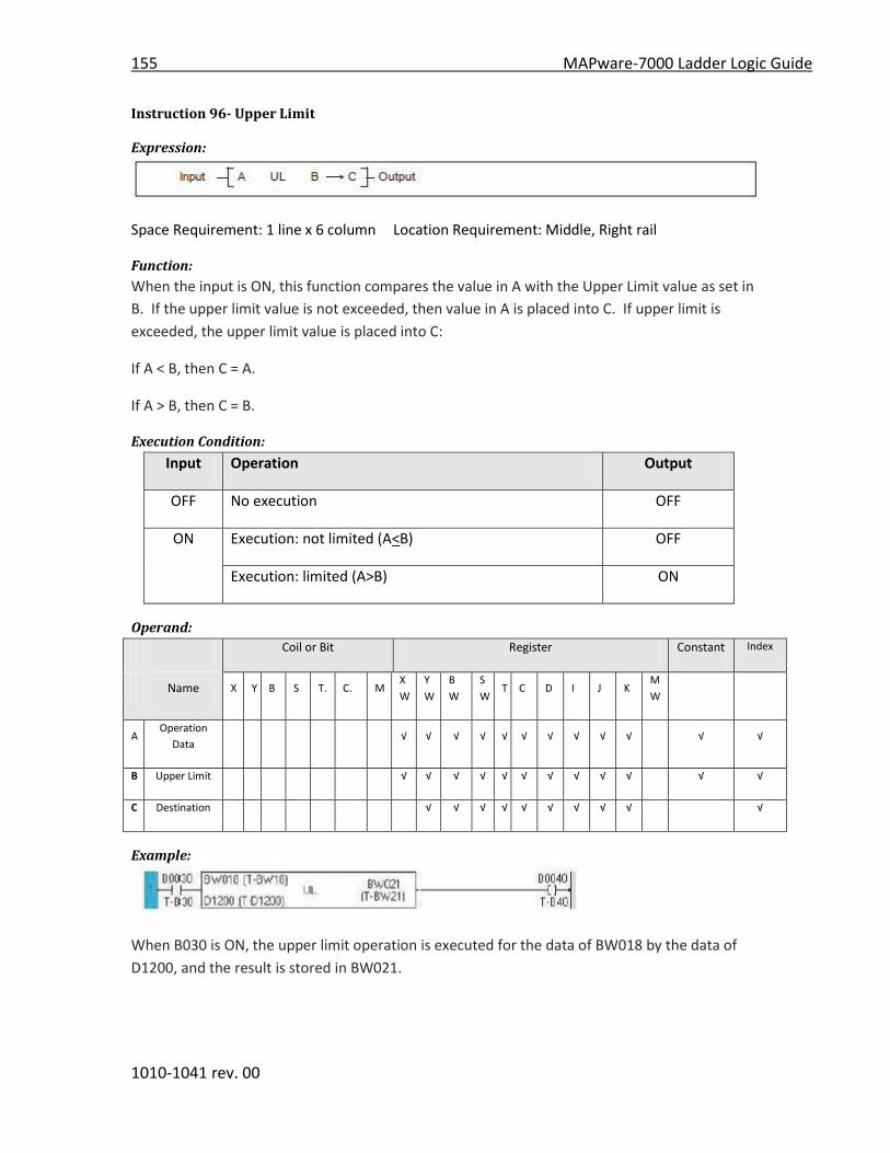
155 MAPware-7000 Ladder Logic Guide
1010-1041 rev. 00
Instruction 96- Upper Limit
Expression:
Space Requirement: 1 line x 6 column Location Requirement: Middle, Right rail
Function:
When the input is ON, this function compares the value in A with the Upper Limit value as set in
B. If the upper limit value is not exceeded, then value in A is placed into C. If upper limit is
exceeded, the upper limit value is placed into C:
If A < B, then C = A.
If A > B, then C = B.
Execution Condition:
Input Operation Output
OFF No execution OFF
ON Execution: not limited (A<B) OFF
Execution: limited (A>B) ON
Operand:
Coil or Bit Register Constant Index
Name X Y B S T. C. M
X
W
Y
W
B
W
S
W T C D I J K
M
W
A Operation
Data √ √ √ √ √ √ √ √ √ √ √ √
B Upper Limit √ √ √ √ √ √ √ √ √ √ √ √
C Destination √ √ √ √ √ √ √ √ √ √
Example:
When B030 is ON, the upper limit operation is executed for the data of BW018 by the data of
D1200, and the result is stored in BW021.

MAPware-7000 Ladder Logic Guide 156
1010-1041 rev. 00
When BW018 is 3000 and D1200 is 4000, 3000 is stored in BW021 and B0040 is OFF.
When BW018 is 4500 and D1200 is 4000, the limit value 4000 is stored in BW021 and B0040 is
ON.
Note
- This instruction deals with the data as signed integer (-32768 to 32767).

157 MAPware-7000 Ladder Logic Guide
1010-1041 rev. 00
Instruction 97- Lower Limit
Expression:
Space Requirement: 1 line x 6 column Location Requirement: Middle, Right rail
Function:
When the input is ON, this function compares the value in A with the Lower Limit value as set in
B. If the lower limit value is not exceeded, then value in A is placed into C. If lower limit is
exceeded, the lower limit value is placed into C:
If A > B, then C = A.
If A < B, then C = B.
Execution Condition:
Input Operation Output
OFF No execution OFF
ON Execution: not limited (A>B) OFF
Execution: limited (A<B) ON
Operand:
Coil or Bit Register Constant Index
Name X Y B S T. C. M
X
W
Y
W
B
W
S
W T C D I J K
M
W
A Operation
Data √ √ √ √ √ √ √ √ √ √ √ √
B Lower Limit √ √ √ √ √ √ √ √ √ √ √ √
C Destination √ √ √ √ √ √ √ √ √ √
Example:
When B031 is ON, the lower limit operation is executed for the data of BW019 by the data of
D1220, and the result is stored in BW022.
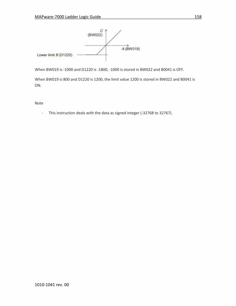
MAPware-7000 Ladder Logic Guide 158
1010-1041 rev. 00
When BW019 is -1000 and D1220 is -1800, -1000 is stored in BW022 and B0041 is OFF.
When BW019 is 800 and D1220 is 1200, the limit value 1200 is stored in BW022 and B0041 is
ON.
Note
- This instruction deals with the data as signed integer (-32768 to 32767).
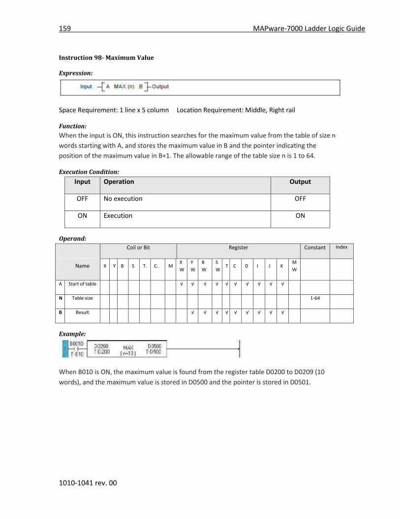
159 MAPware-7000 Ladder Logic Guide
1010-1041 rev. 00
Instruction 98- Maximum Value
Expression:
Space Requirement: 1 line x 5 column Location Requirement: Middle, Right rail
Function:
When the input is ON, this instruction searches for the maximum value from the table of size n
words starting with A, and stores the maximum value in B and the pointer indicating the
position of the maximum value in B+1. The allowable range of the table size n is 1 to 64.
Execution Condition:
Input Operation Output
OFF No execution OFF
ON Execution ON
Operand:
Coil or Bit Register Constant Index
Name X Y B S T. C. M
X
W
Y
W
B
W
S
W T C D I J K
M
W
A Start of table √ √ √ √ √ √ √ √ √ √
N Table size 1-64
B Result √ √ √ √ √ √ √ √ √
Example:
When B010 is ON, the maximum value is found from the register table D0200 to D0209 (10
words), and the maximum value is stored in D0500 and the pointer is stored in D0501.
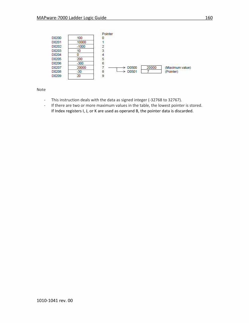
MAPware-7000 Ladder Logic Guide 160
1010-1041 rev. 00
Note
- This instruction deals with the data as signed integer (-32768 to 32767). - If there are two or more maximum values in the table, the lowest pointer is stored.
If Index registers I, J, or K are used as operand B, the pointer data is discarded.

161 MAPware-7000 Ladder Logic Guide
1010-1041 rev. 00
Instruction 99- Minimum Value
Expression:
Space Requirement: 1 line x 5 column Location Requirement: Middle, Right rail
Function:
When the input is ON, this instruction searches for the minimum value from the table of size n
words starting with A, and stores the minimum value in B and the pointer indicating the position
of the minimum value in B+1. The allowable range of the table size n is 1 to 64.
Execution Condition:
Input Operation Output
OFF No execution OFF
ON Execution ON
Operand:
Coil or Bit Register Constant Index
Name X Y B S T. C. M
X
W
Y
W
B
W
S
W T C D I J K
M
W
A Start of table √ √ √ √ √ √ √ √ √ √
N Table size 1-64
B Result √ √ √ √ √ √ √ √ √
Example:
When B011 is ON, the minimum value is found from the register table D0200 to D0209 (10
words), and the minimum value is stored in D0510 and the pointer is stored in D0511.
Note
- This instruction deals with the data as signed integer (-32768 to 32767). - If there is two or more minimum value in the table, the lowest pointer is stored. - If Index register K is used as operand B, the pointer data is discarded.

MAPware-7000 Ladder Logic Guide 162
1010-1041 rev. 00
Instruction 100- Average Value
Expression:
Space Requirement: 1 line x 5 column Location Requirement: Middle, Right rail
Function:
When the input is ON, this instruction calculates the average value of the data stored in the n
registers starting with A, and stores the average value in B. The allowable range of the table size
n is 1 to 64.
Execution Condition:
Input Operation Output
OFF No execution OFF
ON Execution ON
Operand:
Coil or Bit Register Constant Index
Name X Y B S T. C. M
X
W
Y
W
B
W
S
W T C D I J K
M
W
A Start of table √ √ √ √ √ √ √
N Table size 1-64
B Result √ √ √ √ √ √ √ √ √
Example:
When B012 is ON, the average value of the data stored in the register table D0200 to D0209 (10
words), and the average value is stored in D0520.

163 MAPware-7000 Ladder Logic Guide
1010-1041 rev. 00
Instruction 101 Function Generator
Expression:
Space Requirement: 1 line x 6 column Location Requirement: Middle, Right rail
Function:
The Function Generator is used to compute a value f(x) for a given value x stored in Register A.
The value f(x) is then stored into Register C. The computed value is derived based upon a linear
equation as represented by several points in a table of consecutive registers (of size 2n)
beginning with Register B. The table of points represents the X and Y values of a plotted linear
graph. The first half of registers represents the X axis plot points. The second half represent the
Y axis plot points.
Execution Condition:
Input Operation Output
OFF No execution OFF
ON Execution ON
Operand:
Coil or Bit Register Constant Index
Name X Y B S T. C. M
X
W
Y
W
B
W
S
W T C D I J K
M
W
A Input value x √ √ √ √ √ √ √ √ √ √ √
N Parameter
Size 1-32
B Start of
parameters √ √ √ √ √ √ √
C Function
Value f(x) √ √ √ √ √ √ √ √ √
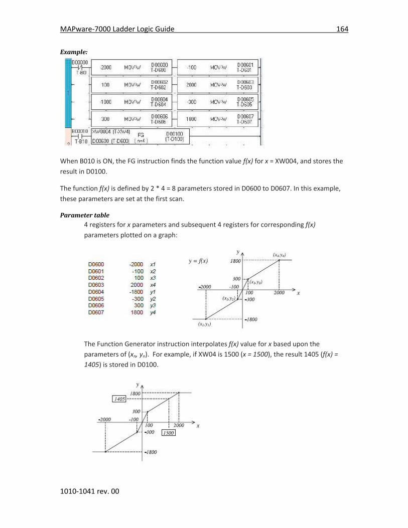
MAPware-7000 Ladder Logic Guide 164
1010-1041 rev. 00
Example:
When B010 is ON, the FG instruction finds the function value f(x) for x = XW004, and stores the
result in D0100.
The function f(x) is defined by 2 * 4 = 8 parameters stored in D0600 to D0607. In this example,
these parameters are set at the first scan.
Parameter table
4 registers for x parameters and subsequent 4 registers for corresponding f(x)
parameters plotted on a graph:
The Function Generator instruction interpolates f(x) value for x based upon the
parameters of (xn, yn). For example, if XW04 is 1500 (x = 1500), the result 1405 (f(x) =
1405) is stored in D0100.

165 MAPware-7000 Ladder Logic Guide
1010-1041 rev. 00
Notes:
The order of the x parameters should be x1 < x2 < ... < xi < ... < xn. In other words, the data table should be constructed so the X values go from lowest value for X1 to the highest value for Xn.
If input value in Register A is smaller than x1, then y1 is given as f(x). In this example, if XW04 is less than D0600 (-2000), then value in D0100 would be D0604 data (-1800).
Similarly, if input value in Register A is greater than xn, then yn is given as f(x). In this example, if XW04 is greater than D0603 (2000), then value in D0100 would be D0607 data (1800).
The valid data range is -32768 to 32767.

MAPware-7000 Ladder Logic Guide 166
1010-1041 rev. 00
Instruction 102- Device Set
Expression:
Space Requirement: 1 line x 3 column Location Requirement: Middle, Right rail
Function:
When the input is ON, the device A is set to ON.
Execution Condition:
Input Operation Output
OFF No execution OFF
ON Execution ON
Operand:
Coil or Bit Register Constant Index
Name X Y B S T. C. M
X
W
Y
W
B
W
S
W T C D I J K
M
W
A Device √ √ √
Example:
When B010 is ON, B025 is set to ON. The state of B025 remains ON even if B010 is set to OFF.
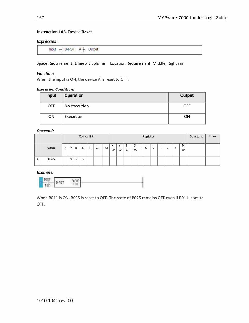
167 MAPware-7000 Ladder Logic Guide
1010-1041 rev. 00
Instruction 103- Device Reset
Expression:
Space Requirement: 1 line x 3 column Location Requirement: Middle, Right rail
Function:
When the input is ON, the device A is reset to OFF.
Execution Condition:
Input Operation Output
OFF No execution OFF
ON Execution ON
Operand:
Coil or Bit Register Constant Index
Name X Y B S T. C. M
X
W
Y
W
B
W
S
W T C D I J K
M
W
A Device √ √ √
Example:
When B011 is ON, B005 is reset to OFF. The state of B025 remains OFF even if B011 is set to
OFF.

MAPware-7000 Ladder Logic Guide 168
1010-1041 rev. 00
Instruction 104- Register Set
Expression:
Space Requirement: 1 line x 3 column Location Requirement: Middle, Right rail
Function:
When the input is ON, the data 0xFFFF is stored in Operand A.
Execution Condition:
Input Operation Output
OFF No execution OFF
ON Execution ON
Operand:
Coil or Bit Register Constant Index
Name X Y B S T. C. M
X
W
Y
W
B
W
S
W T C D I J K
M
W
A Device √ √ √ √ √ √ √ √ √
Example:
When B010 is ON, the data 0xFFFF is stored in BW20. (B320 to B335 are set to ON). The state of
BW20 remains even if B010 is set to OFF.
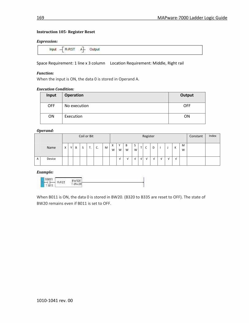
169 MAPware-7000 Ladder Logic Guide
1010-1041 rev. 00
Instruction 105- Register Reset
Expression:
Space Requirement: 1 line x 3 column Location Requirement: Middle, Right rail
Function:
When the input is ON, the data 0 is stored in Operand A.
Execution Condition:
Input Operation Output
OFF No execution OFF
ON Execution ON
Operand:
Coil or Bit Register Constant Index
Name X Y B S T. C. M
X
W
Y
W
B
W
S
W T C D I J K
M
W
A Device √ √ √ √ √ √ √ √ √
Example:
When B011 is ON, the data 0 is stored in BW20. (B320 to B335 are reset to OFF). The state of
BW20 remains even if B011 is set to OFF.

MAPware-7000 Ladder Logic Guide 170
1010-1041 rev. 00
Instruction 106- Set Carry
Expression:
Space Requirement: 1 line x 1 column Location Requirement: Middle, Right rail
Function:
When the input is ON, the carry flag (CF = S000) is set to ON.
Execution Condition:
Input Operation Output
OFF No execution OFF
ON Execution ON
Operand:
No operand is required.
Example:
When B011 is changed from OFF to ON, the carry flag S000 is set to ON.

171 MAPware-7000 Ladder Logic Guide
1010-1041 rev. 00
Instruction 107- Reset Carry
Expression:
Space Requirement: 1 line x 3 column Location Requirement: Middle, Right rail
Function:
When the input is ON, the carry flag (CF = S000) is reset to OFF.
Execution Condition:
Input Operation Output
OFF No execution OFF
ON Execution ON
Operand:
No operand is required.
Example:
When B011 is changed from OFF to ON, the carry flag S000 is reset to OFF.
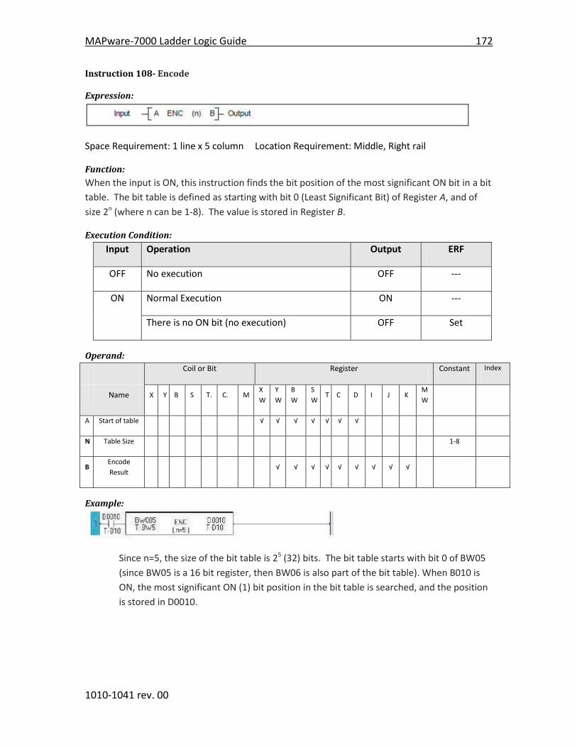
MAPware-7000 Ladder Logic Guide 172
1010-1041 rev. 00
Instruction 108- Encode
Expression:
Space Requirement: 1 line x 5 column Location Requirement: Middle, Right rail
Function:
When the input is ON, this instruction finds the bit position of the most significant ON bit in a bit
table. The bit table is defined as starting with bit 0 (Least Significant Bit) of Register A, and of
size 2n (where n can be 1-8). The value is stored in Register B.
Execution Condition:
Input Operation Output ERF
OFF No execution OFF ---
ON Normal Execution ON ---
There is no ON bit (no execution) OFF Set
Operand:
Coil or Bit Register Constant Index
Name X Y B S T. C. M
X
W
Y
W
B
W
S
W T C D I J K
M
W
A Start of table √ √ √ √ √ √ √
N Table Size 1-8
B Encode
Result √ √ √ √ √ √ √ √ √
Example:
Since n=5, the size of the bit table is 25 (32) bits. The bit table starts with bit 0 of BW05
(since BW05 is a 16 bit register, then BW06 is also part of the bit table). When B010 is
ON, the most significant ON (1) bit position in the bit table is searched, and the position
is stored in D0010.
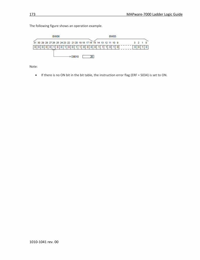
173 MAPware-7000 Ladder Logic Guide
1010-1041 rev. 00
The following figure shows an operation example.
Note:
If there is no ON bit in the bit table, the instruction error flag (ERF = S034) is set to ON.

MAPware-7000 Ladder Logic Guide 174
1010-1041 rev. 00
Instruction 109- Decode
Expression:
Space Requirement: 1 line x 5 column Location Requirement: Middle, Right rail
Function:
When the input is ON, this instruction sets the bit, which is designated by the lower n bits of A,
to ON in the bit table of size 2n bits starting with 0 bit (LSB) of B, and resets all other bits to OFF.
Execution Condition:
Input Operation Output
OFF No execution OFF
ON Execution ON
Operand:
Coil or Bit Register Constant Index
Name X Y B S T. C. M
X
W
Y
W
B
W
S
W T C D I J K
M
W
A Decode
Source √ √ √ √ √ √ √ √ √ √
N Table Size 1-8
B Start of
Table √ √ √ √ √ √
Example:
25 (=32) bits starting with 0 bit of BW05 (B080 to B111) are defined as the bit table.
When B011 is ON, the bit position designated by lower 5 bits of D0011 in the bit table is
set to ON, and all other bits in the table are reset to OFF.
The following figure shows an operation example.

175 MAPware-7000 Ladder Logic Guide
1010-1041 rev. 00
Instruction 110- Bit Count
Expression:
Space Requirement: 1 line x 5 column Location Requirement: Middle, Right rail
Function:
When the input is ON, this instruction counts the number of ON (1) bits of A, and stores the
result in B.
Execution Condition:
Input Operation Output
OFF No execution OFF
ON Execution ON
Operand:
Coil or Bit Register Constant Index
Name X Y B S T. C. M
X
W
Y
W
B
W
S
W T C D I J K
M
W
A Source √ √ √ √ √ √ √ √ √ √ √
B Count Data √ √ √ √ √ √
Example:
When B020 is ON, the number of ON (1) bits of the register BW032 is counted, and the result is
stored in D0102.
The following figure shows an operation example.

MAPware-7000 Ladder Logic Guide 176
1010-1041 rev. 00
Instruction 111- Flip Flop
Expression:
Space Requirement: 2 line x 3 column Location Requirement: Middle, Right rail
Function:
If the Set Input (S) is ON, the device A is set to ON. If the Reset Input (R) is ON, the device A is
reset to OFF.
If both the set and reset inputs are OFF, the device A remains in the current state.
If both the set and reset inputs are ON, the device A is reset to OFF.
The state of the output is the same as the device.
Execution Condition:
Set
Input
Reset
Input
Operation Output
OFF OFF No execution (A remains previous state)
ON Resets A to OFF Same as A
ON OFF Sets A to ON
ON Resets A to OFF
Operand:
Coil or Bit Register Constant Index
Name X Y B S T. C. M
X
W
Y
W
B
W
S
W T C D I J K
M
W
A Device √ √ √
Example:
When X003 is ON, B100 is set to ON. When X004 is ON, B0100 is reset to OFF. If both are ON,
B0100 is reset to OFF.
An example timing diagram is shown below:

177 MAPware-7000 Ladder Logic Guide
1010-1041 rev. 00
Note:
For the set input, direct linking to a connecting point is not allowed. In this case, insert a dummy
contact that is always ON, just before the input.

MAPware-7000 Ladder Logic Guide 178
1010-1041 rev. 00
Instruction 112- Direct I/O
Expression:
Space Requirement: 1 line x 3 column Location Requirement: Middle, Right rail
Function:
Under normal conditions, the external input (XW) and output (YW) registers are updated at the
beginning of each PLC ladder logic scan.
When the input is ON, this instruction immediately updates the target input (XW) or output
(YW) register.
For XW register ... reads the data from targeted input circuit
For YW register ... writes the data into targeted output circuit.
Execution Condition:
Set Input Operation Output
OFF No execution OFF
ON Execution ON
Operand:
Coil or Bit Register Constant Index
Name X Y B S T. C. M
X
W
Y
W
B
W
S
W T C D I J K
M
W
N Register Size 1
A Start of
Registers √ √
Example:
When B010 is ON, the XW00 register is updated immediately.
Note:
The Direct I/O instruction can be programmed in the main program and in the interrupt
program. If this instruction is programmed in both, the instruction in the main program should
be executed in interrupt disable state. Refer to EI (Enable interrupt) and DI (Disable Interrupt)
instructions.

179 MAPware-7000 Ladder Logic Guide
1010-1041 rev. 00
Instruction 113- Set Calendar
Expression:
Space Requirement: 1 line x 3 column Location Requirement: Middle, Right rail
Function:
When the input is ON, the built-in clock/calendar is set to the date and time specified by 6
registers starting with A. If invalid data is contained in the registers, the operation is not
executed and the output is turned ON.
Execution Condition:
Set
Input
Operation Output
OFF No operation OFF
ON Execution (data is valid) OFF
No execution (data is not valid) ON
Operand:
Coil or Bit Register Constant Index
Name X Y B S T. C. M
X
W
Y
W
B
W
S
W T C D I J K
M
W
A Start of
Table √ √ √ √ √ √ √
Example:
When B020 is ON, the clock/calendar is set according to the data of D0050 to D0055, and the
output is OFF (B0031 is OFF).
If D0050 to D0055 contains invalid data, the setting operation is not executed and the output is
turned ON (B0031 comes ON).
D050 (first) to D055 (last) contains

MAPware-7000 Ladder Logic Guide 180
1010-1041 rev. 00
Note:
The day of the week is automatically set accordingly:
Sunday = 1, Monday = 2, Tuesday = 3 ...Saturday = 7.
Currently following system registers (SW) are updated after 2 sec:
Modbus Slave Address SW Address Data
420011 SW10 Date (1 to 31)
420012 SW11 Month (1 to 12)
420013 SW12 Year (00 to 99 <> 2000 to
2099)
420014 SW13 Hour (0 to 23)
420015 SW14 Min (0 to 59)
420016 SW15 Sec (0 to 59)
420017 SW16 Day (1 to 7)
If there is any error then the RTC_Fail Flag (SW 03 Bit 02) is set to ON.
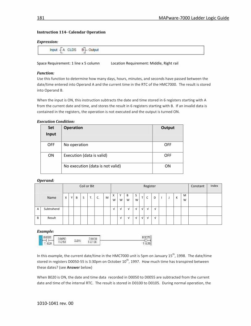
181 MAPware-7000 Ladder Logic Guide
1010-1041 rev. 00
Instruction 114- Calendar Operation
Expression:
Space Requirement: 1 line x 5 column Location Requirement: Middle, Right rail
Function:
Use this function to determine how many days, hours, minutes, and seconds have passed between the
date/time entered into Operand A and the current time in the RTC of the HMC7000. The result is stored
into Operand B.
When the input is ON, this instruction subtracts the date and time stored in 6 registers starting with A
from the current date and time, and stores the result in 6 registers starting with B. If an invalid data is
contained in the registers, the operation is not executed and the output is turned ON.
Execution Condition:
Set
Input
Operation Output
OFF No operation OFF
ON Execution (data is valid) OFF
No execution (data is not valid) ON
Operand:
Coil or Bit Register Constant Index
Name X Y B S T. C. M
X
W
Y
W
B
W
S
W T C D I J K
M
W
A Subtrahend √ √ √ √ √ √ √
B Result √ √ √ √ √ √
Example:
In this example, the current date/time in the HMC7000 unit is 5pm on January 15th
, 1998. The date/time
stored in registers D0050-55 is 3:30pm on October 10th
, 1997. How much time has transpired between
these dates? (see Answer below)
When B020 is ON, the date and time data recorded in D0050 to D0055 are subtracted from the current
date and time of the internal RTC. The result is stored in D0100 to D0105. During normal operation, the
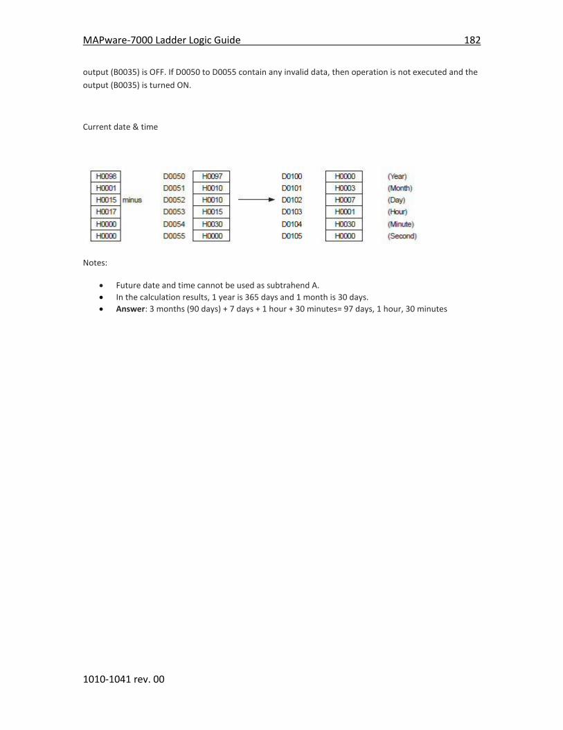
MAPware-7000 Ladder Logic Guide 182
1010-1041 rev. 00
output (B0035) is OFF. If D0050 to D0055 contain any invalid data, then operation is not executed and the
output (B0035) is turned ON.
Current date & time
Notes:
Future date and time cannot be used as subtrahend A.
In the calculation results, 1 year is 365 days and 1 month is 30 days.
Answer: 3 months (90 days) + 7 days + 1 hour + 30 minutes= 97 days, 1 hour, 30 minutes