material studio 5.0 quick start tutorial
TRANSCRIPT

Quick start tutorials
The Quick start tutorials introduce you to some of the basic features of Materials Studio. After reading or working through these tutorials, you will be prepared to start working with Materials Studio.
Quick start covers the following tasks:
Creating a project Opening and viewing 3D documents Sketching a benzamide molecule Viewing and working with study table documents Working with a molecular crystal: studying urea Building an α-quartz crystal Building poly(methyl methacrylate) Saving a project and finishing up
Note. These instructions assume that you will run through all the Quick start tutorials from start to finish without closing and reopening Materials Studio. If you do wish to close Materials Studio, it is recommended that when you start the program again, you load the my quickstart project created in the Creating a project tutorial.
Note. All numbers given in the tutorials are in American English format. See the Localization topic for more information.
Further information
Tutorials Visualizer tutorials
Creating a project
Purpose: Provides an introduction to the concept of a project in Materials Studio. Modules: Materials Visualizer Time: Prerequisites: None
Tip. This tutorial is best carried out with the file extensions for each document displayed. If the file extensions are not displayed in your Project Explorer, refer to the Project Explorer topic for instructions on how to reconfigure.
Introduction
To make the management of documents and workflow as easy as possible, Materials Studio uses the concept of projects. You can view and manage your project data during your Materials Studio session by using the Project Explorer. This system allows you to save, reload, and share Materials Studio projects and to send data and results to other users, either in the form of individual documents or as complete projects.
This tutorial shows you how to start a new project. The project you create can then be used for all the other tutorials in the Quick start section.
This tutorials covers:
To start Materials Studio To create a project To restore default projects settings
Page 1 of 21Quick start tutorials
12/21/2011file://C:\Documents and Settings\Ashish\Local Settings\Temp\~hhED3B.htm

Note. You cannot work within Materials Studio without either creating a new project or opening an existing one.
More detailed instructions on how to use the Project Explorer can be found in the Project management tutorial.
1. To start Materials Studio
From the Windows Start menu, select Programs | Accelrys Materials Studio [version] | Materials Studio.
If you have a Materials Studio icon on your desktop, you can also start Materials Studio by double-clicking on this icon.
When you start Materials Studio, it opens with a dialog called Welcome to Materials Studio. You must either create a new project or load an existing project from this dialog.
Note. If you are starting Materials Studio for the first time, you may see a dialog called Materials Studio File Associations. If this is the case, follow the instructions in this dialog and click on OK.
2. To create a project
On the Welcome to Materials Studio dialog, select Create a new project and then click the OK button.
This opens the New Project dialog.
Select a file location where the project will be stored and enter my quickstart in the File name field, then click the OK button.
This starts your Materials Studio session, working with a project called my quickstart. The Project Explorer should now look like this:
Project Explorer showing the my quickstart project
You have created a new Materials Studio project.
3. To restore default project settings
By default, every new project you create uses the settings defined in the template project that is automatically created by Materials Studio in your Windows user profile, for example, C:\Documents and Settings\[user name]\Application Data\Accelrys\Materials Studio\[version]
\Templates\Normal.stp. For the purposes of these tutorials, you need to ensure that all the settings in the my quickstart project are set to their Accelrys default values.
Select Tools | Settings Organizer from the menu bar to display the Settings Organizer dialog.
The Settings Organizer dialog allows you to define a template project containing default settings for Materials Studio modules and various tools in the Materials Visualizer. You can also use the Settings Organizer dialog to exchange settings from external projects into the current project or to restore any of the settings in the current project to their Accelrys default values.
On the Settings Organizer dialog, click on the Materials Studio icon at the top of the tree view in the
Page 2 of 21Quick start tutorials
12/21/2011file://C:\Documents and Settings\Ashish\Local Settings\Temp\~hhED3B.htm

All settings in current project window to select all the modules and Visualizer tools. Click on the Reset button.
All the default settings for the selected Materials Studio modules and Materials Visualizer tools are reset to their Accelrys default values.
Further information
Quick start tutorials Opening and viewing 3D documents Sketching a benzamide molecule Viewing and working with study table documents Working with a molecular crystal: studying urea Building an α-quartz crystal Building poly(methyl methacrylate) Saving a project and finishing up
Opening and viewing 3D documents
Purpose: Provides an introduction to the concept of documents in Materials Studio. Modules: Materials Visualizer Time: Prerequisites: Creating a project
Tip. This tutorial is best carried out with the file extensions for each document displayed. If the file extensions are not displayed in your Project Explorer, refer to the Project Explorer topic for instructions on how to reconfigure.
Introduction
Materials Studio employs a variety of different document types - 3D Atomistic and Mesoscale, text, chart, HTML, study table, grid, script, and forcefield documents. In the Quick start tutorials, you will work primarily with the 3D Atomistic document type. Documents are managed within projects, which record the general workflow as documents are created and saved.
This tutorial covers:
To import a structure To adjust display styles To change the view of 3D structures To select various types of objects
You should carry out this tutorial in the my quickstart project you created in the Creating a project tutorial.
1. To import a structure
The Materials Visualizer enables you to open a document in the 3D Viewer and adjust the graphical display style of the structure that you are viewing using an array of convenient tools.
Select File | Import... from the menu bar.
The Import Document dialog is displayed.
Note. This dialog can also be opened using the Import button on the Standard toolbar.
Navigate to and select Examples/Documents/3D Model/TON.msi, then click the Open button.
Page 3 of 21Quick start tutorials
12/21/2011file://C:\Documents and Settings\Ashish\Local Settings\Temp\~hhED3B.htm

A 3D Viewer containing the conventional zeolite Theta-1 unit cell is displayed. A document called TON.xsd is now shown as part of the my quickstart project in the Project Explorer. Note that the file extension has changed from .msi to .xsd, the XML-based native Materials Studio format for 3D structures.
2. To adjust display styles
Right-click in the 3D Viewer to display the shortcut menu, select Display Style from the list.
Shortcut menu
This opens the Display Style dialog.
On the Atom tab, click on each option in the Display style section to view the structure using the Line, Stick, Ball and stick, CPK, and Polyhedron display styles. When you have finished, return to the CPK display style. Select the Lattice tab of the Display Style dialog.
The Lattice tab contains controls for changing the periodic lattice display style.
In the Lattice section, select the None, Dashed line, Line, and Stick styles in turn. Note their effect on how the lattice is displayed in the 3D Viewer. Make sure that the lattice display style is set to Line.
The tabs available on the Display Style dialog are dependent on the type of objects present in the active document.
Right-click in the 3D Viewer and select Lighting from the shortcut menu.
This opens the Lighting dialog. The Preview box on the left-hand side of the dialog displays a sphere with an arrow on its surface. You can use this control to change the settings for up to three light sources.
Hover the mouse cursor over the sphere until the cursor changes to a hand. Click and drag over the sphere to change the direction of the incoming light, indicated by the arrow.
The lighting in the 3D view of TON.xsd responds interactively as you move the arrow.
Close the Lighting dialog by clicking on the Close button in the top right. On the Atom tab of the Display Style dialog, select the Ball and stick option to set the. Click on the
Close button to close the Display Style dialog.
3. To change the view of 3D structures
3D structures can be manipulated in a variety of different ways using the buttons on the 3D Viewer toolbar.
Page 4 of 21Quick start tutorials
12/21/2011file://C:\Documents and Settings\Ashish\Local Settings\Temp\~hhED3B.htm
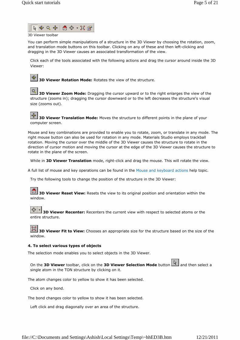
3D Viewer toolbar
You can perform simple manipulations of a structure in the 3D Viewer by choosing the rotation, zoom, and translation mode buttons on this toolbar. Clicking on any of these and then left-clicking and dragging in the 3D Viewer causes an associated transformation of the view.
Click each of the tools associated with the following actions and drag the cursor around inside the 3D Viewer:
3D Viewer Rotation Mode: Rotates the view of the structure.
3D Viewer Zoom Mode: Dragging the cursor upward or to the right enlarges the view of the structure (zooms in); dragging the cursor downward or to the left decreases the structure's visual size (zooms out).
3D Viewer Translation Mode: Moves the structure to different points in the plane of your computer screen.
Mouse and key combinations are provided to enable you to rotate, zoom, or translate in any mode. The right mouse button can also be used for rotation in any mode. Materials Studio employs trackball rotation. Moving the cursor over the middle of the 3D Viewer causes the structure to rotate in the direction of cursor motion and moving the cursor at the edge of the 3D Viewer causes the structure to rotate in the plane of the screen.
While in 3D Viewer Translation mode, right-click and drag the mouse. This will rotate the view.
A full list of mouse and key operations can be found in the Mouse and keyboard actions help topic.
Try the following tools to change the position of the structure in the 3D Viewer:
3D Viewer Reset View: Resets the view to its original position and orientation within the window.
3D Viewer Recenter: Recenters the current view with respect to selected atoms or the entire structure.
3D Viewer Fit to View: Chooses an appropriate size for the structure based on the size of the window.
4. To select various types of objects
The selection mode enables you to select objects in the 3D Viewer.
On the 3D Viewer toolbar, click on the 3D Viewer Selection Mode button and then select a single atom in the TON structure by clicking on it.
The atom changes color to yellow to show it has been selected.
Click on any bond.
The bond changes color to yellow to show it has been selected.
Left click and drag diagonally over an area of the structure.
Page 5 of 21Quick start tutorials
12/21/2011file://C:\Documents and Settings\Ashish\Local Settings\Temp\~hhED3B.htm
This draws a selection box and selects any objects (atoms and bonds in this case) inside the box.
Double-click on any atom or bond in the TON structure.
This selects the whole structure.
Click or double-click anywhere in the 3D Viewer away from the structure to deselect everything.
Click on the Close button to close the 3D Viewer by. When you are prompted to save the document as part of the project, click the Yes button.
Further information
Quick start tutorials Creating a project Sketching a benzamide molecule Viewing and working with study table documents Working with a molecular crystal: studying urea Building an α-quartz crystal Building poly(methyl methacrylate) Saving a project and finishing up
Sketching a benzamide molecule
Purpose: Provides an introduction to the sketching tools available in the Materials Visualizer. Modules: Materials Visualizer Time: Prerequisites: Creating a project
Tip. This tutorial is best carried out with the file extensions for each document displayed. If the file extensions are not displayed in your Project Explorer, refer to the Project Explorer topic for instructions on how to reconfigure.
Introduction
Chemists have to deal with a wide range of small molecules and chemical intermediates on a daily basis. To be able to easily create models of such molecules is important in any molecular modeling environment. Benzamide is a typical example of a small molecule that might be created and studied with Materials Studio.
This tutorial covers:
To create a new 3D Atomistic document To change to ball and stick default display style To sketch the ring and atom chain To sketch with oxygen To edit the element type To edit the bond type To adjust Hydrogen and Clean To convert from Kekulé to resonant bond representation To monitor and adjust distances
You should carry out this tutorial in the my quickstart project you created in the Creating a project tutorial.
This is the structure of benzamide that you will be building:
Page 6 of 21Quick start tutorials
12/21/2011file://C:\Documents and Settings\Ashish\Local Settings\Temp\~hhED3B.htm

Benzamide
1. To create a new 3D Atomistic document
Select File | New... from the menu bar to open the New Document dialog. Select 3D Atomistic and click the OK button.
This opens a new 3D Viewer. A corresponding item called 3D Atomistic.xsd is shown in the Project Explorer.
Right-click on the 3D Atomistic.xsd item in the Project Explorer and select Rename from the shortcut menu. Type my_benzamide and press the ENTER key.
Select File | Save from the menu bar or click the Save button on the Standard toolbar.
You have created a new 3D Atomistic document called my_benzamide.xsd in the my quickstart project.
2. To change to ball and stick default display style
Materials Studio's versatile sketching tools allow you to sketch in any display style. For this example, you will use ball and stick as the default display style.
Select Modify | Default Atom Style from the menu bar.
This opens the Default Atom Style dialog.
Select the Ball and stick option from the Display Style section. Click on the Close button in the top right corner to close the Default Atom Style dialog.
The default display style for this project is set to ball and stick.
3. To sketch the ring and atom chain
Click the Sketch Ring button on the Sketch toolbar. Move the mouse cursor to the 3D Viewer.
The cursor now looks like a pencil to show that you are in sketching mode. The number next to the cursor indicates the size of the ring about to be sketched. You can change the ring size by pressing any number key from 3 to 8.
Check that the number beside the cursor is 6. Left-click in the 3D Viewer.
A six-membered carbon ring is sketched. Note that holding down the ALT key and clicking the left mouse button sketches an aromatic ring with resonant bonds.
Page 7 of 21Quick start tutorials
12/21/2011file://C:\Documents and Settings\Ashish\Local Settings\Temp\~hhED3B.htm

Click the Sketch Atom button on the Sketch toolbar.
You have chosen the general atom sketching tool, which can sketch with any element. By default, it sketches with carbon. You will attach a two-carbon side chain to the ring.
Hover the cursor over one of the carbons in the ring until it is highlighted in blue, then left-click to anchor the bond to this carbon. Move the cursor and left-click again to sketch a carbon atom, then move the cursor again and double-click to terminate the two-carbon chain attached to the carbon ring.
Another way of terminating the chain would be to click once to sketch the final carbon atom and then press the ESC key. Notice that bonds are added automatically between the newly sketched atoms.
Note. You can undo any mistakes that you make by clicking the Undo button on the Standard toolbar.
4. To sketch with oxygen
On the Sketch toolbar, click on the options arrow associated with the Sketch Atom button
to show a list of alternative elements for sketching. Select Oxygen. Hover the cursor over the first carbon of the side chain and, when it is highlighted in blue, left-click to anchor the bond to this carbon. Now move the cursor away from this point and double-click to sketch an oxygen atom and terminate the chain.
Click on the 3D Viewer Selection Mode button on the 3D Viewer toolbar. (If the 3D Viewer toolbar is not displayed, select View | Toolbars from the menu bar and choose 3D Viewer).
You are now in selection mode.
5. To edit the element type
Click on the end carbon in the side chain to select it.
When selected correctly, it is highlighted in yellow.
Click on the options arrow associated with the Modify Element button on the Sketch toolbar to show a list of elements. Choose Nitrogen. Click anywhere in the 3D Viewer to deselect the atom.
The carbon atom has changed to a nitrogen atom.
6. To edit the bond type
In the 3D Viewer, click the center of the C-O bond to select it.
When the bond is selected, it is highlighted in yellow.
Hold down the SHIFT key and then click on three alternate bonds in the carbon ring.
You should now have four bonds selected: three C-C bonds in the carbon ring and the C-O bond.
Click on the options arrow associated with the Modify Bond Type button on the Sketch toolbar and select Double Bond from the dropdown list.
Page 8 of 21Quick start tutorials
12/21/2011file://C:\Documents and Settings\Ashish\Local Settings\Temp\~hhED3B.htm
All four selected bonds change to double bonds.
Deselect everything by clicking anywhere away from the structure in the 3D Viewer.
7. To adjust Hydrogen and Clean
Now you can add hydrogens automatically to the structure, without having to sketch them individually.
Click on the Adjust Hydrogen button on the Sketch toolbar to add the appropriate number of hydrogen atoms to the structure.
Tidy the geometry of the structure by clicking the Clean button on the Sketch toolbar.
This modifies the geometry of the structure so that bond lengths, angles, and torsions are chemically reasonable.
8. To convert from Kekulé to resonant bond representation
Materials Studio's Bond Calculation tool allows easy conversion of the bonding representation between Kekulé and resonant.
Select Build | Bonds from the menu bar.
This opens the Bond Calculation dialog.
In the Options section of the Bonding Scheme tab, make sure that Convert representation to is checked and click on the options arrow associated with the list box to the right (which is set to Kekule by default). Select Resonant from the dropdown list and click the Calculate button. Clicking the Close button
to close the Bond Calculation dialog.
The bonds in the phenyl ring are now displayed as resonant. In this example, however, you will retain the Kekulé bonding representation.
Select Edit | Undo Calculate Bonds from the menu bar or, alternatively, click on the Undo button
on the Standard toolbar.
The bond calculation is undone and the bonding in the phenyl ring reverts to the Kekulé representation.
Note. You can undo multiple steps by clicking on the options arrow associated with the Undo button
.
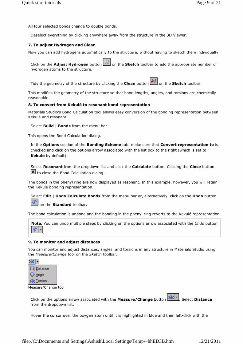
9. To monitor and adjust distances
You can monitor and adjust distances, angles, and torsions in any structure in Materials Studio using the Measure/Change tool on the Sketch toolbar.
Measure/Change tool
Click on the options arrow associated with the Measure/Change button . Select Distance from the dropdown list. Hover the cursor over the oxygen atom until it is highlighted in blue and then left-click with the
Page 9 of 21Quick start tutorials
12/21/2011file://C:\Documents and Settings\Ashish\Local Settings\Temp\~hhED3B.htm

mouse. Repeat this action on the carbon atom to which the oxygen atom is bonded.
A distance monitor appears, with the distance displayed in Ångstroms.
With the cursor in the 3D Viewer, away from the molecule, left-click and drag the cursor upwards to
increase the C-O bond length. Click the Clean button .
The numerical display of the distance monitor changes to reflect the increase in bond length and the decrease as a result of the cleaning process.
Click the 3D Viewer Rotation Mode button on the 3D Viewer toolbar. Click and drag in the 3D Viewer to rotate the model and view it from different angles.
Note that the color of the distance monitor changes from red to green when it becomes inactive. You can now use the context-sensitive Properties Explorer to view information about the model you have created.
Select View | Explorers | Properties Explorer from the menu bar.
This opens the Properties Explorer, which is automatically docked to the left-hand side of the Materials Studio window. You can undock this and any other explorer by clicking on its title bar and dragging to another position in the window, including the bottom of the screen, where it will dock again.
Click the options arrow associated with the Filter list box in the Properties Explorer and select Molecule from the dropdown list to display a list of the properties of the molecule.
Properties Explorer with values for benzamide
The value of the centroid vector will vary, depending on where in the 3D Viewer you started to sketch the molecule. You can change the width of the Property and Value columns by clicking and dragging on the separator line between the two column headings.
Click on any atom in the benzamide molecule to select it.
The atom appears highlighted in yellow to show it is selected.
Note. The Properties Explorer is context sensitive and automatically displays the properties of the selected atom.
Click on any single bond in the benzamide molecule to select it.
When selected correctly, the bond is highlighted in yellow and the atom previously selected should be deselected; the Properties Explorer now displays the properties of the selected bond.
You can directly edit certain properties of the structure through the Properties Explorer.
Page 10 of 21Quick start tutorials
12/21/2011file://C:\Documents and Settings\Ashish\Local Settings\Temp\~hhED3B.htm
In the Properties Explorer, double-click on BondType.
This opens the Edit BondType dialog.
Click on the options arrow associated with the list box to display a list of different bond types and select Double, then click the OK button.
The single bond changes to a double bond.
Click on the Undo button on the Standard toolbar to return the bond type to single bond.
Close the 3D view of the my_benzamide.xsd document by clicking on the Close button . When prompted to save the document, click the Yes button.
Further information
Quick start tutorials Creating a project Opening and viewing 3D documents Viewing and working with study table documents Working with a molecular crystal: studying urea Building an α-quartz crystal Building poly(methyl methacrylate) Saving a project and finishing up
Viewing and working with study table documents
Purpose: Provides an introduction to the concept of study tables in Materials Studio. Modules: Materials Visualizer Time: Prerequisites: Creating a project
Tip. This tutorial is best carried out with the file extensions for each document displayed. If the file extensions are not displayed in your Project Explorer, refer to the Project Explorer topic for instructions on how to reconfigure.
Introduction
Study tables are an important part of the workflow in Materials Studio. These documents (.std files) are displayed as a spreadsheet, combining mathematical expression evaluation and data control with chemical awareness. The cells of a study table can contain alphanumeric strings, 3D structures, or charts.
This tutorial shows you how to open a study table, import molecular structures, and calculate some basic properties of the imported molecules:
To open a new study table document To insert molecular structures into a study table To view structures in the study table Other types of structures supported by the study table To calculate basic descriptors To manipulate data shown in the Study Table Viewer
Note. In order to complete this tutorial, you will need a QSAR license.
Page 11 of 21Quick start tutorials
12/21/2011file://C:\Documents and Settings\Ashish\Local Settings\Temp\~hhED3B.htm
You should carry out this tutorial in the my quickstart project you created in the Creating a project tutorial.
1. To open a new study table document
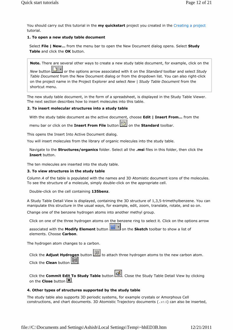
Select File | New... from the menu bar to open the New Document dialog opens. Select Study Table and click the OK button.
Note. There are several other ways to create a new study table document, for example, click on the
New button or the options arrow associated with it on the Standard toolbar and select Study Table Document from the New Document dialog or from the dropdown list. You can also right-click on the project name in the Project Explorer and select New | Study Table Document from the shortcut menu.
The new study table document, in the form of a spreadsheet, is displayed in the Study Table Viewer. The next section describes how to insert molecules into this table.
2. To insert molecular structures into a study table
With the study table document as the active document, choose Edit | Insert From... from the
menu bar or click on the Insert From File button on the Standard toolbar.
This opens the Insert Into Active Document dialog.
You will insert molecules from the library of organic molecules into the study table.
Navigate to the Structures/organics folder. Select all the .msi files in this folder, then click the Insert button.
The ten molecules are inserted into the study table.
3. To view structures in the study table
Column A of the table is populated with the names and 3D Atomistic document icons of the molecules. To see the structure of a molecule, simply double-click on the appropriate cell.
Double-click on the cell containing 135benz.
A Study Table Detail View is displayed, containing the 3D structure of 1,3,5-trimethylbenzene. You can manipulate this structure in the usual ways, for example, edit, zoom, translate, rotate, and so on.
Change one of the benzene hydrogen atoms into another methyl group.
Click on one of the three hydrogen atoms on the benzene ring to select it. Click on the options arrow
associated with the Modify Element button on the Sketch toolbar to show a list of elements. Choose Carbon.
The hydrogen atom changes to a carbon.
Click the Adjust Hydrogen button to attach three hydrogen atoms to the new carbon atom.
Click the Clean button .
Click the Commit Edit To Study Table button . Close the Study Table Detail View by clicking
on the Close button .
4. Other types of structures supported by the study table
The study table also supports 3D periodic systems, for example crystals or Amorphous Cell constructions, and chart documents. 3D Atomistic Trajectory documents (.xtd) can also be inserted,
Page 12 of 21Quick start tutorials
12/21/2011file://C:\Documents and Settings\Ashish\Local Settings\Temp\~hhED3B.htm

with each frame of the trajectory file being placed in its own row in the study table. These structures can either be inserted as before or directly inserted from the Project Explorer.
Note. Mesoscale structures are not supported by the study table document type.
5. To calculate basic descriptors
A view of part of the study table is shown below.
Study table document containing structures
Note. The cells in the top row of the study table, containing column labels A, B, etc., are known as "column headings". The cells in the second row, containing descriptions of column content, for example, Structures, are called the "column descriptions".
The value of a study table becomes apparent when calculating properties of multiple structures.
In the Study Table, click on the column heading A.
The entire column turns blue, indicating that it is selected.
Note. You can deselect at any time (cancel the current selection) by pressing the ESC key.
Click on the Models button on the QSAR Models toolbar to display the Models dialog. From the Output column, select Element count. Hold down the CTRL key and also select Atom
count. Click the Run button and click the Close button to close the Models dialog.
Note. Default behavior for an Element count is to count the number of carbon atoms. You can use
the Edit Model tool on the Models dialog to change this.
Wait for the job to finish; it should take only a few seconds.
A job completion message will appear when the calculation is over. The results of the calculation are reported in columns B and C.
Click on OK to close the Job Completed dialog.
Page 13 of 21Quick start tutorials
12/21/2011file://C:\Documents and Settings\Ashish\Local Settings\Temp\~hhED3B.htm

6. To manipulate data shown in the Study Table Viewer
Several tools on the Study Table Viewer toolbar become useful now.
Select column B, containing the atom count data. Click the Filter Selection button on the Study Table Viewer toolbar.
A second data sheet, comprising part of the same study table, is created. The other columns are not displayed in this view. This option can be helpful when large sets of data are involved. Now remove the filtering from the new sheet.
Click on the options arrow associated with the Filter Selection button and select Show All from the dropdown list.
All columns are now displayed.
Note. Similar filtering can also be performed on rows.
Select column B, containing the atom count data. Click the Sort Ascending button .
The data are sorted in order of ascending numbers of atoms.
With column B selected, click on the Quick Plot button on the Study Table Viewer toolbar.
A chart document (.xcd) containing a plot of Atom count vs. Row Number is generated.
Click anywhere in the Study Table to make it the active document. Select the empty column D. Click
on the Define Function button to open the Define Function dialog. In the Expression text box, enter C/B. In the Name text box, enter Ratio. In the Description text box, enter Fraction of carbon. Click the OK button.
The fraction of atoms in each molecule which are carbon is calculated and displayed in column D.
Select Window | Close All to close all of the windows. When prompted to save, click the Yes to All button.
This is the end of the tutorial.
Further information
Quick start tutorials Creating a project Opening and viewing 3D documents Sketching a benzamide molecule Working with a molecular crystal: studying urea Building an α-quartz crystal Building poly(methyl methacrylate) Saving a project and finishing up
Working with a molecular crystal: studying urea
Purpose: Provides an introduction to the crystal building tools available in the Materials Visualizer. Modules: Materials Visualizer Time:
Page 14 of 21Quick start tutorials
12/21/2011file://C:\Documents and Settings\Ashish\Local Settings\Temp\~hhED3B.htm
Prerequisites: Creating a project
Tip. This tutorial is best carried out with the file extensions for each document displayed. If the file extensions are not displayed in your Project Explorer, refer to the Project Explorer topic for instructions on how to reconfigure.
Introduction
Pharmaceuticals, agrochemicals, pigments, dyes, specialty chemicals, and explosives are all, at some stage during the manufacturing process, crystalline materials. Being able to model such structures can extend our understanding of them and, ultimately, help us to control properties such as solubility, shelf life, morphology, bioavailability, color, shock sensitivity, vapor pressure, and density. Urea, used in this exercise, is a simple example of a molecular crystalline material.
This tutorial covers:
To open a molecular crystal document To calculate hydrogen bonds To adjust the display range for the crystal cell To change the lattice display style To examine the structure's hydrogen bonding
You should carry out this tutorial in the my quickstart project you created in the Creating a project tutorial.
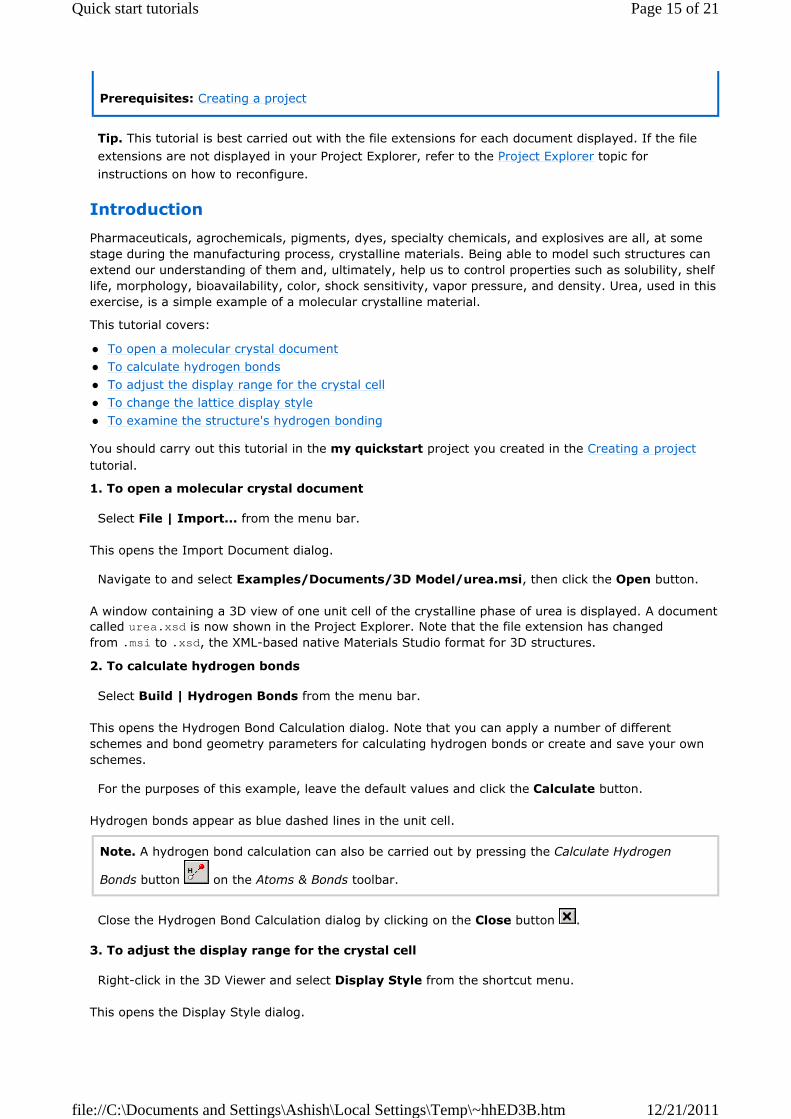
1. To open a molecular crystal document
Select File | Import... from the menu bar.
This opens the Import Document dialog.
Navigate to and select Examples/Documents/3D Model/urea.msi, then click the Open button.
A window containing a 3D view of one unit cell of the crystalline phase of urea is displayed. A document called urea.xsd is now shown in the Project Explorer. Note that the file extension has changed from .msi to .xsd, the XML-based native Materials Studio format for 3D structures.
2. To calculate hydrogen bonds
Select Build | Hydrogen Bonds from the menu bar.
This opens the Hydrogen Bond Calculation dialog. Note that you can apply a number of different schemes and bond geometry parameters for calculating hydrogen bonds or create and save your own schemes.
For the purposes of this example, leave the default values and click the Calculate button.
Hydrogen bonds appear as blue dashed lines in the unit cell.
Note. A hydrogen bond calculation can also be carried out by pressing the Calculate Hydrogen
Bonds button on the Atoms & Bonds toolbar.
Close the Hydrogen Bond Calculation dialog by clicking on the Close button .
3. To adjust the display range for the crystal cell
Right-click in the 3D Viewer and select Display Style from the shortcut menu.
This opens the Display Style dialog.
Page 15 of 21Quick start tutorials
12/21/2011file://C:\Documents and Settings\Ashish\Local Settings\Temp\~hhED3B.htm

Select the Lattice tab on the Display Style dialog to display the options for changing the lattice display style. In the Display style section, change the Max value in the A row to 2.00. Do the same for the Max value in the B and C rows.
The Display style controls give the option to display a user-defined range and number of unit cells, including the ability to input fractions of unit cell lengths. You should now have a 2 × 2 × 2 lattice of urea that shows the hydrogen bonding scheme more clearly.
4. To change the lattice display style
In the Lattice section, select None. Close the Display Style dialog by clicking the Close button .
5. To examine the structure's hydrogen bonding
Rotate the view to study the hydrogen bonding network. To help you see the hydrogen bonding
clearly, click the Reset View button on the 3D Viewer toolbar. Use the up, down, right, and left arrow keys to rotate the model by 45° increments.
Close urea.xsd by clicking the Close button . When prompted to save, click the Yes button.
Further information
Quick start tutorials Creating a project Opening and viewing 3D documents Sketching a benzamide molecule Viewing and working with study table documents Building an α-quartz crystal Building poly(methyl methacrylate) Saving a project and finishing up
Building an α-quartz crystal
Purpose: Provides an introduction to the crystal building tools available in the Materials Visualizer. Modules: Materials Visualizer Time: Prerequisites: Creating a project
Tip. This tutorial is best carried out with the file extensions for each document displayed. If the file extensions are not displayed in your Project Explorer, refer to the Project Explorer topic for instructions on how to reconfigure.
Introduction
Modeling of inorganic crystalline materials is a very important area, particularly relevant to applications such as the design of heterogeneous catalysts, for example zeolite catalysts, or analysis of mineral samples during oil and gas exploration. This tutorial shows you how to build an α-quartz crystal and, in doing so, introduces you to some of Materials Studio's crystal building functionality.
This tutorial covers:
To build the α-quartz crystal To add silicon and oxygen atoms To compare two versions of the crystal
Page 16 of 21Quick start tutorials
12/21/2011file://C:\Documents and Settings\Ashish\Local Settings\Temp\~hhED3B.htm
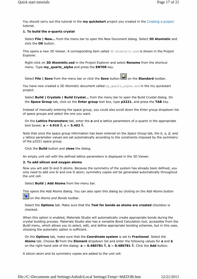
You should carry out this tutorial in the my quickstart project you created in the Creating a project tutorial.
1. To build the α-quartz crystal
Select File | New... from the menu bar to open the New Document dialog. Select 3D Atomistic and click the OK button.
This opens a new 3D Viewer. A corresponding item called 3D Atomistic.xsd is shown in the Project Explorer.
Right-click on 3D Atomistic.xsd in the Project Explorer and select Rename from the shortcut menu. Type my_quartz_alpha and press the ENTER key.
Select File | Save from the menu bar or click the Save button on the Standard toolbar.
You have now created a 3D Atomistic document called my_quartz_alpha.xsd in the my quickstart project.
Select Build | Crystals | Build Crystal... from the menu bar to open the Build Crystal dialog. On the Space Group tab, click on the Enter group text box, type p3221, and press the TAB key.
Instead of manually entering the space group, you could also scroll down the Enter group dropdown list of space groups and select the one you want.
On the Lattice Parameters tab, enter the a and c lattice parameters of α-quartz in the appropriate text boxes: a = 4.910 Å, c = 5.402 Å.
Note that once the space group information has been entered on the Space Group tab, the b, α, β, and γ lattice parameter values are set automatically according to the constraints imposed by the symmetry of the p3221 space group.
Click the Build button and close the dialog.
An empty unit cell with the defined lattice parameters is displayed in the 3D Viewer.
2. To add silicon and oxygen atoms
Now you will add Si and O atoms. Because the symmetry of the system has already been defined, you only need to add one Si and one O atom; symmetry copies will be generated automatically throughout the unit cell.
Select Build | Add Atoms from the menu bar.
This opens the Add Atoms dialog. You can also open this dialog by clicking on the Add Atoms button
on the Atoms and Bonds toolbar.
Select the Options tab. Make sure that the Test for bonds as atoms are created checkbox is checked.
When this option is enabled, Materials Studio will automatically create appropriate bonds during the crystal building process. Materials Studio also has a versatile Bond Calculation tool, accessible from the Build menu, which allows you to select, edit, and define appropriate bonding schemes, but in this case, choosing the automatic option is sufficient.
On the Options tab, make sure that the Coordinate system is set to Fractional. Select the Atoms tab. Choose Si from the Element dropdown list and enter the following values for a and b on the right-hand side of the dialog: a = 0.480781 Å, b = 0.480781 Å. Click the Add button.
A silicon atom and its symmetry copies are added to the unit cell.
Page 17 of 21Quick start tutorials
12/21/2011file://C:\Documents and Settings\Ashish\Local Settings\Temp\~hhED3B.htm
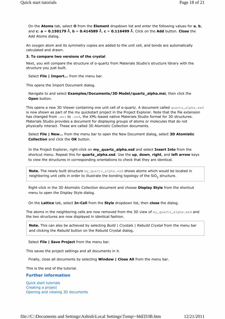
On the Atoms tab, select O from the Element dropdown list and enter the following values for a, b, and c: a = 0.150179 Å, b = 0.414589 Å, c = 0.116499 Å. Click on the Add button. Close the Add Atoms dialog.
An oxygen atom and its symmetry copies are added to the unit cell, and bonds are automatically calculated and drawn.
3. To compare two versions of the crystal
Next, you will compare the structure of α-quartz from Materials Studio's structure library with the structure you just built.
Select File | Import... from the menu bar.
This opens the Import Document dialog.
Navigate to and select Examples/Documents/3D Model/quartz_alpha.msi, then click the Open button.
This opens a new 3D Viewer containing one unit cell of α-quartz. A document called quartz_alpha.xsd is now shown as part of the my quickstart project in the Project Explorer. Note that the file extension has changed from .msi to .xsd, the XML-based native Materials Studio format for 3D structures. Materials Studio provides a document for displaying groups of atoms or molecules that do not physically interact. These are called 3D Atomistic Collection documents.
Select File | New... from the menu bar to open the New Document dialog, select 3D Atomistic Collection and click the OK button. In the Project Explorer, right-click on my_quartz_alpha.xsd and select Insert Into from the shortcut menu. Repeat this for quartz_alpha.xsd. Use the up, down, right, and left arrow keys to view the structures in corresponding orientations to check that they are identical.
Note. The newly built structure my_quartz_alpha.xsd shows atoms which would be located in neighboring unit cells in order to illustrate the bonding topology of the SiO2 structure.
Right-click in the 3D Atomistic Collection document and choose Display Style from the shortcut menu to open the Display Style dialog. On the Lattice tab, select In-Cell from the Style dropdown list, then close the dialog.
The atoms in the neighboring cells are now removed from the 3D view of my_quartz_alpha.xsd and the two structures are now displayed in identical fashion.
Note. This can also be achieved by selecting Build | Crystals | Rebuild Crystal from the menu bar and clicking the Rebuild button on the Rebuild Crystal dialog.
Select File | Save Project from the menu bar.
This saves the project settings and all documents in it.
Finally, close all documents by selecting Window | Close All from the menu bar.
This is the end of the tutorial.
Further information
Quick start tutorials Creating a project Opening and viewing 3D documents
Page 18 of 21Quick start tutorials
12/21/2011file://C:\Documents and Settings\Ashish\Local Settings\Temp\~hhED3B.htm
Sketching a benzamide molecule Viewing and working with study table documents Working with a molecular crystal: studying urea Building poly(methyl methacrylate) Saving a project and finishing up
Building poly(methyl methacrylate)
Purpose: Provides an introduction to the polymer building tools available in the Materials Visualizer. Modules: Materials Visualizer Time: Prerequisites: Creating a project
Tip. This tutorial is best carried out with the file extensions for each document displayed. If the file extensions are not displayed in your Project Explorer, refer to the Project Explorer topic for instructions on how to reconfigure.
Introduction
Poly(methyl methacrylate), or PMMA, is important as a commercial thermoplastic material, particularly for glazing applications. It is typically produced by free radical polymerization of methyl methacrylate using peroxide or azo initiators, or by thermal or photochemical initiation. In this example, you will use Materials Studio's polymer building features to build a 20-mer of isotactic PMMA, which could then be used for further simulation and study of the structure and properties.
This tutorial covers:
To build isotactic PMMA To select and label an individual repeat unit To study the structure
You should carry out this tutorial in the my quickstart project you created in the Creating a project tutorial.
1. To build isotactic PMMA
Materials Studio gives you the option of building homopolymers, block copolymers, random copolymers, and dendrimers.
Select Build | Build Polymers | Homopolymer from the menu bar.
This opens the Homopolymer dialog.
On the Polymerize tab, select acrylates from the Library dropdown list. Select methyl_methacrylate from the Repeat unit dropdown list. Examine the Tacticity dropdown list.
It is possible to build polymers in isotactic, syndiotactic, or atactic form. You are going to build an isotactic methylmethacrylate polymer.
The Tacticity should be set to Isotactic. Set the Chain length to 20. On the Advanced tab and set the Torsion to 60.
You have now set up the Polymer Builder to build isotactic PMMA with 20 repeat units in the molecule.
Click the Build button and close the dialog.
Page 19 of 21Quick start tutorials
12/21/2011file://C:\Documents and Settings\Ashish\Local Settings\Temp\~hhED3B.htm
A new 3D Atomistic document called Polymethyl_methacrylate.xsd is created containing your constructed PMMA molecule and is displayed in the 3D Viewer.
Click on the Clean button on the Sketch toolbar to rearrange the structure to a more reasonable geometry.
Normally, further geometry optimization would be necessary, the Forcite module can be used to achieve this.
2. To select and label an individual repeat unit
First you will change the display style of the structure.
Right-click in the 3D Viewer and select Display Style from the shortcut menu to open the Display Style dialog. On the Atom tab, select the Line option in the Display style section.
The display style of the whole structure is changed to line.
Click on an atom anywhere in the PMMA molecule (you may need to zoom in to be able to do this easily).
The selected atom is highlighted in yellow.
Right-click anywhere in the 3D Viewer to display the shortcut menu, choose Select Repeat Unit methyl_methacrylate from the shortcut menu.
The whole of a single methyl methacrylate repeat unit is selected and highlighted in yellow.
On the Atom tab of the Display Style dialog, select the Ball and stick option. Close the Display
Style dialog by clicking on the Close button .
The selected repeat unit is now displayed in the ball and stick style.
With the repeat unit selected, right-click in the 3D Viewer and choose Label from the shortcut menu to open the Label dialog. Select Repeat Unit from the Object Type dropdown list, and in the Properties field, select Name. In the Font section of the dialog, change the font size to 24 and the Color to green through the color chooser. Click the Apply button and close the Label dialog.
A green label with the name of the repeat unit is added next to the selected repeat unit.
3. To study the structure
Click in Polymethyl_methacrylate.xsd 3D view to deselect the repeat unit. Rotate, zoom, and translate to study the structure, either by selecting different modes using the buttons on the 3D Viewer toolbar or by using the mouse and keyboard shortcuts detailed in the Opening and viewing 3D documents tutorial.
Close Polymethyl_methacrylate.xsd by clicking on the Close button . When prompted to save the document, click the Yes button.
Further information
Quick start tutorials Creating a project Opening and viewing 3D documents
Page 20 of 21Quick start tutorials
12/21/2011file://C:\Documents and Settings\Ashish\Local Settings\Temp\~hhED3B.htm

Sketching a benzamide molecule Viewing and working with study table documents Working with a molecular crystal: studying urea Building an α-quartz crystal Saving a project and finishing up
Saving a project and finishing up
Purpose: Illustrates how to save documents and close projects in Materials Studio. Modules: Materials Visualizer Time: Prerequisites: Creating a project
Tip. This tutorial is best carried out with the file extensions for each document displayed. If the file extensions are not displayed in your Project Explorer, refer to the Project Explorer topic for instructions on how to reconfigure.
You have now created your first Materials Studio project.
1. To save the project
Double-click on each of the following items in the Project Explorer: my_benzamide.xsd, urea.xsd, my_quartz_alpha.xsd, Polymethyl_methacrylate.xsd.
The four documents are opened in the Materials Studio workspace.
Select Window | Tile Horizontally from the menu bar.
The 3D views of the four documents are tiled within the Materials Studio workspace.
Select File | Save Project from the menu bar.
You have now reached the end of these Quick start tutorials. The project settings and all the documents are now saved in the project my quickstart. If you open this project again, it will automatically open with the same four 3D Viewers displayed and the same items showing in the Project Explorer. You can now either create a new project, load another existing project (both using the appropriate options on the File menu), or exit Materials Studio.
To exit Materials Studio, select File | Exit from the menu bar.
Further information
Quick start tutorials Creating a project Opening and viewing 3D documents Sketching a benzamide molecule Viewing and working with study table documents Working with a molecular crystal: studying urea Building an α-quartz crystal Building poly(methyl methacrylate)
Page 21 of 21Quick start tutorials
12/21/2011file://C:\Documents and Settings\Ashish\Local Settings\Temp\~hhED3B.htm