maxi harrow - rite way mfg....
TRANSCRIPT

Operation & Maintenance
Manual
MAXI HARROW
OPERATORS MANUAL & PARTS LIST


1
Maxi Harrow
Contents
SECTION 1 PAGE
INTRODUCTION 1
MANUAL & EQUIPMENT DETAILS 2
SPECIFICATIONS 3
PRE-DELIVERY INSPECTION 4
SERVICE & WARRANTY POLICY 5 - 6
SAFETY RECOMMENDATIONS 7
DECAL LOCATIONS 8 - 11
MAINTENANCE 12 - 15
OPERATING INSTRUCTIONS 16 - 23
HYDRAULIC SCHEMATIC 24 - 29
GRADE CHART 30
TORQUE CHART 31
Table of Contents
SECTION 2 PAGE
PARTS 1 - 25


Maxi Harrow
SECTION 1


1
Maxi Harrow
Introduction
We are pleased to welcome you as an owner of a product from RITE WAY MFG. This machinery is the culmination of years of agricultural and engineering experience and has been designed to deliver you with many years of successful operation service.
For the most efficient operation of your Maxi Harrow Bar we have provided
this Owner’s Manual. In this manual we have included proper maintenance and
functional procedures to offer maximum longevity for your new equipment. Before
operating we urge a careful study of this manual to provide a thorough under-
standing of your new harrow. We also recommend that you take care of this manu-
al so it will be available for future reference. Should your manual become lost or
destroyed a new copy can be obtained from your Rite Way Manufacturing dealer.
We will also be happy to answer any questions you might have concerning the use
or care of this product.
Rite Way Manufacturing Co. Ltd. P.O. Box 328
Imperial, Saskatchewan, Canada S0G 2J0
PH: 306-963-2180 Fax: 306-963-2660
Web Site: www.ritewaymfg.com Email: [email protected]
Thank you for making the decision to purchase a RITE WAY

2
Maxi Harrow
Manual Details
Unit Model Number Maxi Harrow
Manual Revision Number P 3.0
Manual Revision Date Apr 30, 2012
Manual Serial Number Range 13-0842—13-0891
Owner / Equipment Information
Serial Number of Unit
Date of Purchase
Dealer Name
Dealer Address
Dealer Phone Number
Salesman Name
Salesman Phone Number
Notes
The area below is provided for the owner / end-user to make notes regarding the equipment.
Manual Information

3
Maxi Harrow
Specifications
Hydraulic System Standard unit requires - 6 Hydraulic Banks.
Heavy duty hydraulic cylinders.
Chrome plated steel hydraulic lines
Specifications
Wings 8” x 8” x .250w wall wing tube
11L-15 tires
General Information 25º to 40º Hydraulic harrow gang angling from tractor cab
Transport width of 14′-11"
Adjustable hitch height c/w perfect hitch clevis
12.5L x 15 all weather (main) and 11L-15 (wing) tires
8” x 8” x .250w wall wing tube and centre bar
Light kit
Slow moving sign kit
Main Frame Heavy duty universal joint pivots
6” x 4” x 0.188w tube A-Frame tube
Tires - 12.5L x 15 all weather tires
Optional Tires - 16.5L x 16.11, 6 ply
Options
Valmar granular applicator mounting kit
Acremeter kit
Section Model 6 8 10
Working Width at 25° 38′ 51′ 65′
Working Width at 40° 36′ 49′ 63′
# of Long Harrow Sections 5 7 9
# of Short Harrow Sections 1 1 1
Transp. Width 14′ - 11" 14′ - 11" 14′ - 11"
Transp. Height 9′ - 5-3/4 " 9′ - 5-3/4 " 9′ - 5-3/4 "
Transp. Length 36′ - 3/16 " 42′ - 7-7/16 " 49′ - 4-1/16 "
Ground Clearance 18.5” 18.5” 18.5”
Approx. Weight (lbs.) 7590 9360 11060
4
Maxi Harrow
General
Remove wrapping and wash unit, removing all road debris. (Road salt, mud, snow, etc.)
Inspect paint, decals and general appearance of unit.
Verify that the owners manual is in the manual storage tube.
Verify ‘SLOW MOVING VEHICLE’ sign (SMV) is on unit (if applicable)
Verify that jacks are with the unit and function properly.
Check wheel bolts for proper torque.
Check for proper tire pressure (PSI).
Verify that the wheel hubs are lubricated.
Verify that locking pins and / or ram locks are in place.
Lubricate all components as per operators manual recommendation.
Check that all bolts and fasteners are at the proper torque specifications.
(NOTE: All cap screws that have lock nuts join moving pieces should not be tightened completely, they must allow movement. i.e. Spring pressure kits, rock shaft connector, draft arm, etc.
Check sprocket alignment and chain tension. (If applicable)
Check locking collars and set screws for proper tension. (If applicable)
Verify operation of lights. (If applicable)
Verify the unit moves ‘IN’ and ‘OUT’ of transport without any binding.
Verify that tires are tracking properly when in transport mode.
Pre-delivery Inspection Check List
Hydraulics
Insure that all hydraulic hoses and lines are routed properly and secured.
Verify that all hydraulic fittings / hoses are secure and there are no oil leaks.
Inspect all cylinders for leakage and the cylinder shaft for rust, pits, or scratches.
Verify operation of all hydraulic functions - Cycle hydraulic cylinders to remove air from the system.
Delivery
Verify that ‘The customer is aware of warning decals and proper jack placement for transport.’.
Verify that ‘The customer is aware of proper operation and transportation of the unit’.
Verify that ‘The customer has received an operators manual’.
Explain all maintenance and service intervals to the customer (From operators manual).
Advise the customer of grease zerk locations and maintenance schedules.
Level the unit per operators manual and instruct the customer on the proper procedures.
Pre-delivery Inspection Check List
Pre-delivery Inspection Completed By (Sign Below)
Pre-delivery Inspection Confirmed By (Sign Below)

5
Maxi Harrow
Service & Warranty Policy
Rite Way Manufacturing Co. Ltd. (hereafter referred to as Rite way) warrants each new machine to
be free from defects in materials and workmanship for a period of one (1) year from date of purchase under
normal agricultural use and service. In addition, Rite Way will supply at no charge, (F.O.B Rite Way Factory)
any part that has failed within the 2nd year. Rite Way’s obligation under this warranty is limited to the repair
or replacement of any defective parts of the equipment at its own discretion.
Any alterations, modifications or additions done to a finished product will void this warranty unless
prior written permission from Rite Way is obtained.
Items that are not manufactured by Rite Way are covered by the warranty of the supplier of these
items. We will therefore extend, without assuming any responsibility, any warranty given to us by our suppli-
ers.
This warranty shall-not apply to any machine, that in the company’s judgment has be subjected to
misuse, negligence or accident. In no event shall the owner be entitled to recover costs for incidental, special
or consequential damages such as, but not limited to; Loss of crop, loss of profit or revenue, other commer-
cial losses, inconvenience or rental costs.
This warranty shall not apply unless Rite Way or its designated dealer is promptly notified of claimed
defects and the allegedly defective part is held for inspection.
Repair parts purchased for machines ‘Out of Warranty’, are warranted to be free from defects in ma-
terial and workmanship under normal use and service for a period of ninety (90) days from the date of deliv-
ery to the customer.
The warranty shall only become valid when delivery notification for warranty is received by Rite Way
within 20 days of the completion of sale.
OWNER’S / USERS OBLIGATION: It is the responsibility of the user to read the Operators Manual and un-
derstand the safe and correct operating procedures as it pertains to the operation of the product, and to lubri-
cate and maintain the product according to the maintenance schedule in the Manual.
The user is responsible for inspecting the machine, and for having parts repaired or replaced when
continued use of the product could cause damage or excessive wear to any other parts. It is the user’s re-
sponsibility to deliver their machine to a Rite Way dealer for service or replacement of defective parts which
are covered by the standard warranty.
Rite Way will not by held responsible for charges such as transportation, fuel, lodging when a deal-
er / dealer representative travels to a customer location for warranty or inspection.
Service & Warranty Policy

6
Maxi Harrow
Service & Warranty Policy
1. All claims must be handled through a dealer / distributor. All claims must be submitted on
a properly completed claim form within 30 days of the date of repair.
2. A warranty registration claim form must be on file at Rite Way Mfg. to validate a warranty
claim.
3. Defective parts are to be held at the dealer / distributor’s place of business until the war-
ranty claim form has been processed. Rite Way will advise when parts can be released.
4. Parts that require inspection by Rite Way personnel must be accompanied by a Return
Goods Form number, and must be sent by pre-paid freight. Rite Way will refund pre-paid
freight charges on any items determined to be defective.
5. Rite Way will not assume responsibility for repairs or expenses incurred without authoriza-
tion. Warranty labour in excess of $150.00 must be authorized before such work is per-
formed and photographs before and after repairs are required.
6. Warranty labour is to be claimed on the warranty claim form, only if the warranty labour
was performed by the dealer. Travel time is not covered by warranty and should not be
included. Rite Way reserves the right to adjust or allocate labour times and values based
on its experience.
7. It is the responsibility of the dealer to ensure that the warranty registration forms are
properly completed and returned to Rite Way Mfg., Imperial, SK.
Service & Warranty Claim Procedure

7
Maxi Harrow
Safety Recommendations
1. Read the manual thoroughly and understand before operating or working on the machine.
2. Study all safety and warning decals on the implement.
3. Most accidents occur because of neglect or carelessness.
4. Do not allow riders on the tractor or implement during operation.
5. Do not allow children on or near the machine.
6. Connect the implement hitch to the tractor before operating the hydraulic system.
NOTE: Be aware of any hydraulic leaks.
7. Always throttle the tractor down and use caution when connecting the implement to the trac-
tor hitch.
NOTE: Never stand between the tractor and implement.
8. Lower the hitch jack onto firm ground and chock the tires when un-hooking implement from
tractor.
NOTE: Ensure the unit is on level ground prior to un-hooking tractor.
9. Exercise extra caution when working on hillsides or near ditches.
10. Ensure that the tractor draw-bar is pinned during transport.
11. Maximum speed while transporting the Harrow is 25 mph (40 km/h). If a truck is used to
pull the machine it is strongly recommended using a 3/4 ton with added weight or larger.
12. Ensure that the Harrow drawbar is lowered to the ground before doing any work on ma-
chine.
NOTE: If it is necessary to work on machine with the drawbar raised,
ensure that cylinders are locked in position using the lock pin.
13. Do not work on this machine when hydraulic system is under pressure.
14. Observe all laws and regulations when transporting unit on public roads.
15. Do not transport this machine on public roads unless all safety & maintenance checks have
been completed.
Safety Recommendations
This machine will provide years of trouble-free & safe opera-tion IF all maintenance and safety instructions are followed.

8
Maxi Harrow
Decal Locations
Decal Locations—6 section

9
Maxi Harrow
ITEM # DESCRIPTION Part #
1 AMBER REFLECTOR 060-0009
2 IMPORTANT BLOCK WHEELS BEFORE UNHOOKING 060-0015
3 CAUTION ESCAPING FLUID HAZARD ESCAPING HYDRAULIC FLU-ID UNDER PRESSURE CAN PENETRATE THE SKIN CAUSING SE-RIOUS INJURY
060-0011
4 WARNING CHECK AND TIGHTEN HUB AND WHEEL BOLTS 060-0067
5 ATTENTION ENSURE THAT ALL CYLINDER SHAFTS ARE RE-TRACTED OR GREASED FOR EXTENDED PERIODS OF STORAGE OR SHAFT CORROSION MAY OCCUR
060-0038
6 WARNING LOWER OR BLOCK ELEVATED COMPONENTS BEFORE SERVICING OR WHEN LEAVING THIS MACHINE. ELEVATED COM-PONENTS CAN FALL AND CAUSE SERIOUS INJURY
060-0028
7 WARNING THIS MACHINE CAN KILL OR INJURE UNLESS SAFETY PRECAUSTIONS ARE NOT TAKEN AND OBSERVED
8 GREASE EVERY EIGHT HOURS 060-0046
9 WARNING STAND CLEAR OF HITCH TONGUE WHEN UNHOOKING FROM IMPLEMENT. INJURY MAY OCCUR DUE TO HITCH RISING, IF JACKS ARE NOT SECURELY PLACED
060-0029
10 IMPORTANT HYDRAULIC HOSE APPLICATION 060-0061
11 RITE WAY MFG (LARGE) 060-0072
12 RITE WAY MFG (SMALL) 060-0092
13 SERIAL NUMBER PLATE 060-0034
14 RED REFLECTOR 060-0022
Decal Locations - 6 Section Harrow
Decal Locations - 6 Section Harrow
10
Maxi Harrow
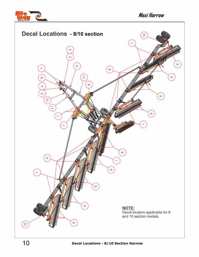
- 8/10 section
Decal Locations - 8/10 Section Harrow

11
Maxi Harrow
Decal Locations - 8/10 Section Harrow
Decal Locations - 8/10 Section Harrow
ITEM # DESCRIPTION Part #
1 AMBER REFLECTOR 060-0009
2 IMPORTANT BLOCK WHEELS BEFORE UNHOOKING 060-0015
3 CAUTION ESCAPING FLUID HAZARD ESCAPING HYDRAULIC FLU-ID UNDER PRESSURE CAN PENETRATE THE SKIN CAUSING SE-RIOUS INJURY
060-0011
4 WARNING CHECK AND TIGHTEN HUB AND WHEEL BOLTS 060-0067
5 ATTENTION ENSURE THAT ALL CYLINDER SHAFTS ARE RE-TRACTED OR GREASED FOR EXTENDED PERIODS OF STORAGE OR SHAFT CORROSION MAY OCCUR
060-0038
6 WARNING LOWER OR BLOCK ELEVATED COMPONENTS BEFORE SERVICING OR WHEN LEAVING THIS MACHINE. ELEVATED COM-PONENTS CAN FALL AND CAUSE SERIOUS INJURY
060-0028
7 WARNING THIS MACHINE CAN KILL OR INJURE UNLESS SAFETY PRECAUSTIONS ARE NOT TAKEN AND OBSERVED
8 GREASE EVERY EIGHT HOURS 060-0046
9 WARNING STAND CLEAR OF HITCH TONGUE WHEN UNHOOKING FROM IMPLEMENT. INJURY MAY OCCUR DUE TO HITCH RISING, IF JACKS ARE NOT SECURELY PLACED
060-0029
10 IMPORTANT HYDRAULIC HOSE APPLICATION 060-0061
11 RITE WAY MFG (LARGE) 060-0072
12 RITE WAY MFG (SMALL) 060-0092
13 SERIAL NUMBER PLATE 060-0034
14 RED REFLECTOR 060-0022
12
Maxi Harrow
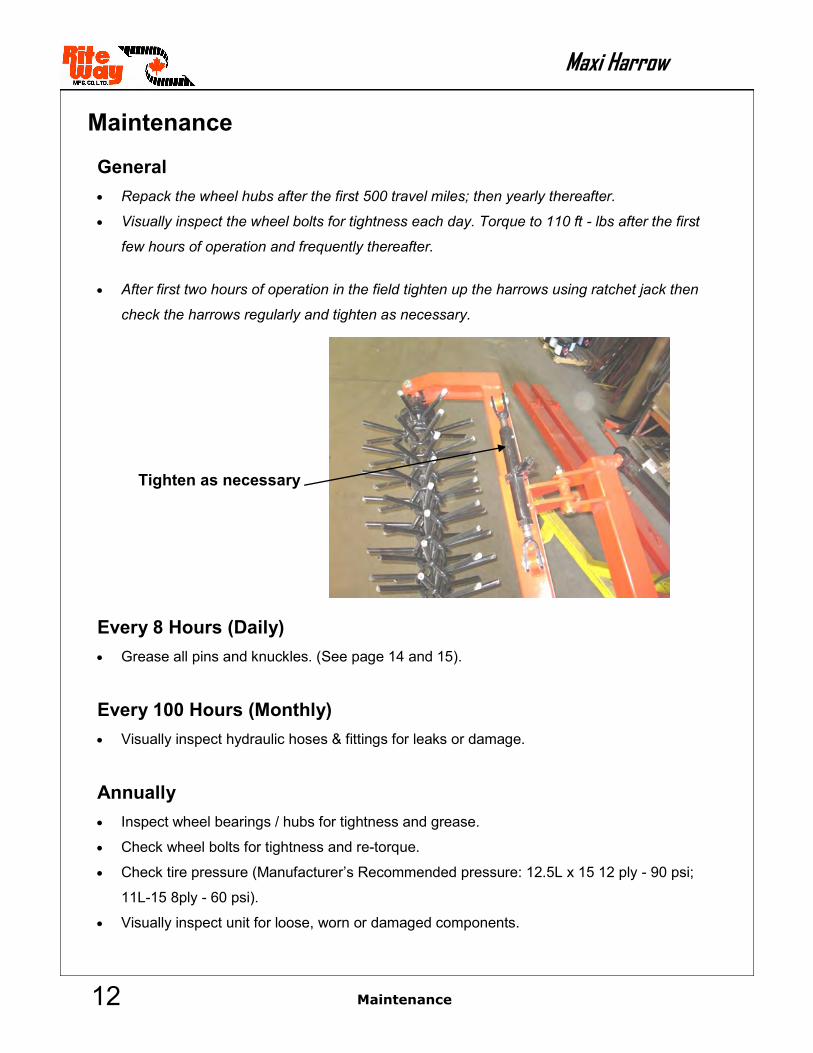
Maintenance
General
Repack the wheel hubs after the first 500 travel miles; then yearly thereafter.
Visually inspect the wheel bolts for tightness each day. Torque to 110 ft - lbs after the first
few hours of operation and frequently thereafter.
After first two hours of operation in the field tighten up the harrows using ratchet jack then
check the harrows regularly and tighten as necessary.
Every 8 Hours (Daily)
Grease all pins and knuckles. (See page 14 and 15).
Every 100 Hours (Monthly)
Visually inspect hydraulic hoses & fittings for leaks or damage.
Annually
Inspect wheel bearings / hubs for tightness and grease.
Check wheel bolts for tightness and re-torque.
Check tire pressure (Manufacturer’s Recommended pressure: 12.5L x 15 12 ply - 90 psi;
11L-15 8ply - 60 psi).
Visually inspect unit for loose, worn or damaged components.
Maintenance
Tighten as necessary

13
Maxi Harrow
Maintenance
Storage
Coat any exposed cylinder shafts with thick oil or grease.
Ensure that parking jacks are situated on firm ground.
Lock all applicable safety pins into place.
NOTE: All fasteners with locknuts that are used to join moving pieces
should not be tightened completely to allow for movement.
Maintenance
14
Maxi Harrow
Maintenance
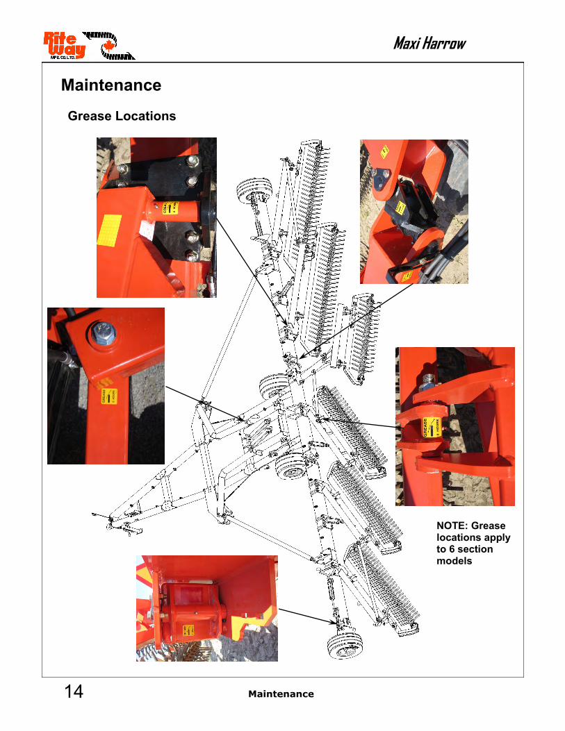
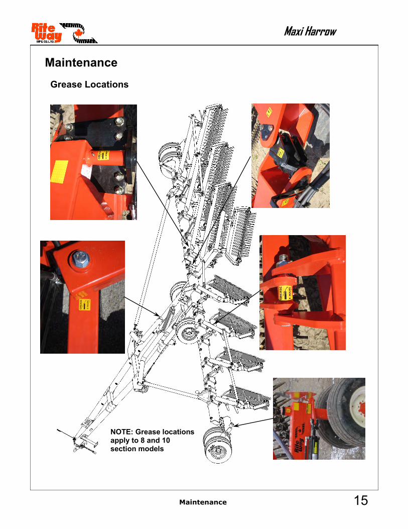
Maintenance
Grease Locations
NOTE: Grease locations apply to 6 section models
15
Maxi Harrow
Maintenance
Maintenance
Grease Locations
NOTE: Grease locations apply to 8 and 10 section models
16
Maxi Harrow
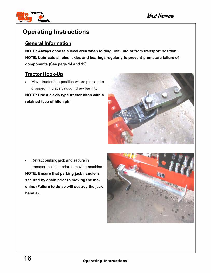
Operating Instructions
General Information
NOTE: Always choose a level area when folding unit into or from transport position.
NOTE: Lubricate all pins, axles and bearings regularly to prevent premature failure of
components (See page 14 and 15).
Tractor Hook-Up
Move tractor into position where pin can be
dropped in place through draw bar hitch
NOTE: Use a clevis type tractor hitch with a
retained type of hitch pin.
Retract parking jack and secure in
transport position prior to moving machine
NOTE: Ensure that parking jack handle is
secured by chain prior to moving the ma-
chine (Failure to do so will destroy the jack
handle).
Operating Instructions

17
Maxi Harrow
Clean hydraulic hose ends prior to coupling with tractor hydraulic system.
You require three hydraulic outlets to operate the machine properly:
Yellow - lifting/lowering main frame Red - adjust harrow gang angle Green - wheel turning system
Tractor Disconnecting
Ensure that the harrow sections are either fully raised in transport position, or fully lowered
into field position.
NOTE: If the Harrow is in transport position, ensure that all lock pins are in place.
Check the A-frame tires front and back before disconnecting from the tractor.
Lower parking jack (s) into position, lowering until upward pressure is applied at wings and
the harrow hitch is raised off of the tractor clevis.
NOTE: Ensure that the jacks are placed on firm ground prior to unhooking.
NOTE: If jacks are not placed or set properly, the hitch may rise suddenly.
Cornering Field Work
During field operation, always make turns to that the inside wing wheel tire continues to ro-
tate. Sharp turns will increase the stress applied to the auto-fold system & inside wing wheel
and may cause damage to the unit.
Operating Instructions
Operating Instructions

18
Maxi Harrow
Operating Instructions
Leveling Instructions
1. Move unit to field position on level ground.
2. Measure from bottom of tubing on the A-frame to ground by the wheel.
3. Measure from bottom of tubing on the A-frame to ground by hitch.
4. Adjust hitch clevis accordingly to match wheel distance.
Note: Hitch measurement may be slightly less than the measurement by the wheel
Transport to Field Position
1. Hook-up tractor according to instructions.
2. When entering the field from transport, find a location that is as level as possible.
3. Unlock safety arm and remove wing wheel safety pins (see below).
4. Reduce tractor speed to as slow as possible (Low Gear, Less than 1000 rpm).
Operating Instructions
The base model Maxi Harrow is supplied with pivoting wing wheels that require back-ing-up of only a few feet to lock into field position.

19
Maxi Harrow
5. Activate green hydraulic line to pivot wing wheels approximately 45°.
6. Slowly move tractor forward allowing wings to open approximately 45°.
7. Stop the unit and lower the harrows using the yellow hyd. lines until front tip of the harrow
makes contact with the ground.
Operating Instructions
Operating Instructions

20
Maxi Harrow
8. Slowly move the tractor forward and continue lowering the harrows at the same time until ful-
ly lowered to field position. As the wings are lowered, make sure the cable (item C) allows
the locking cams (item B) to grasp the swing arm (item A).
9. You are ready to harrow. Adjust angle of harrows on the go using red hyd. lines to your con-
dition. Fully open cylinder for aggressive harrowing and completely close cylinder for light
harrowing. See table below for angle of aggression descriptions.
Operating Instructions
Operating Instructions

21
Maxi Harrow
Operating Instructions
Operating Instructions
Harrowing Activity
Light Medium Aggressive
Suggested Angle of Aggression
25° 35° 40°
Function Get rid of weeds – chemical free Dry wet spots on your field for earlier seeding
Knock down and break up heavy trash, including corn stalks Leave trash on surface
Smooth rough fields, breaking up large lumps Remove root balls Rejuvenate pasture and hay fields
Accomplish Aerates wet soil, allow-ing you to seed 3-7 days sooner Levels and breaks up no-till corn stocks
Levels small ridges and produces superior seed-beds Knocks down corn stalks leaving roots in the ground Fills cracks on the dry land to conserve moisture
Levels large ridges and rough fields Incorporates chemicals efficiently (up to 95% on first pass) Breaks down large clumps

22
Maxi Harrow
Operating Instructions
Field to Transport Position (All models)
1. Bring unit to a complete stop in a level area of the field.
2. Ensure the auto fold lock opens (item
B) as the harrows are lifted (yellow hyd.
lines) to the upright position.
3. Raise harrow sections into transport position.
NOTE: Ensure that draft arm lock has released while lifting cable each side.
Operating Instructions

23
Maxi Harrow
4. Activate pivot wing wheel green hyd. Lines - rotate wheels fully 90 degrees. The 6 and 8/10
section Maxi models are shown, respectively.
5. Slowly drive unit forward until wings have moved to transport position.
6. Engage harrow lift lock and insert wing wheel lock pins.
7. Disconnect tractor. See page 17.
Operating Instructions
Operating Instructions

24
Maxi Harrow
Hydraulic Schematic, A-Frame
T o p L i n e S e t U p Bottom Line Set Up
BB
SS
22
77
53
11
33
5
1313
3
11
55
4 4
66
66
8
9
12
12
10
10
12
9
1 8
A-Frame Hydraulic Assembly

25
Maxi Harrow
Hydraulic Schematic, A-Frame
Item # Part # Description
1 030-5982 35 THC - 24 - 175 Hydraulic Cylinder, 3/4” ORB Ports in line
2 308-0001 Pioneer Coupling - Poppet Style, 1/2” quick connect
3 311-2083 Hydraulic Steel Line - 83” Straight (x4)
4 311-2083 Hydraulic Steel Line, 83” Bent 10° @ 17” (x8)
5 311-2083 Hydraulic Steel Line, 83” Bent 80° @ 2” (x4)
6 313-3084 3/8” Hydraulic Hose, 3/8” JIC Male x 3/8” JIC Male - 84”
7 313-5096 3/8” Hydraulic Hose, 3/8” JIC Male x 1/2” NPT Male - 96”
8 313-7845 3/8” Hydraulic Hose, 3/8” JIC Male x 3/8” Sw. Female - 45”
9 313-7923 3/8” Hydraulic Hose, 3/8” Sw. Female x 3/8” Sw. Female - 23”
10 318-5705 Tee, 3/8” JIC Sw. Female (Run) x 3/8” JIC Male (Run, Branch)
11 318-5707 Tee, 3/8” JIC Male (x2 Run) x 3/8” JIC Sw. Female (Branch)
12 319-5710 90° Elbow, 1/2” ORB Male x 3/8” JIC Male
13 324-0031 Nipple, 3/8” JIC Male (x2)
A-Frame Hydraulic Assembly
26
Maxi Harrow
Le f t W ing Se t Up
1
4
2
6
5
7
9
98
11 9
12
Right Wing Set Up
3
4
5
6
7
9
89
12
B
S
B
S
B
S
BS
B S
12
Front
Front
12
10
1210
12
9
12
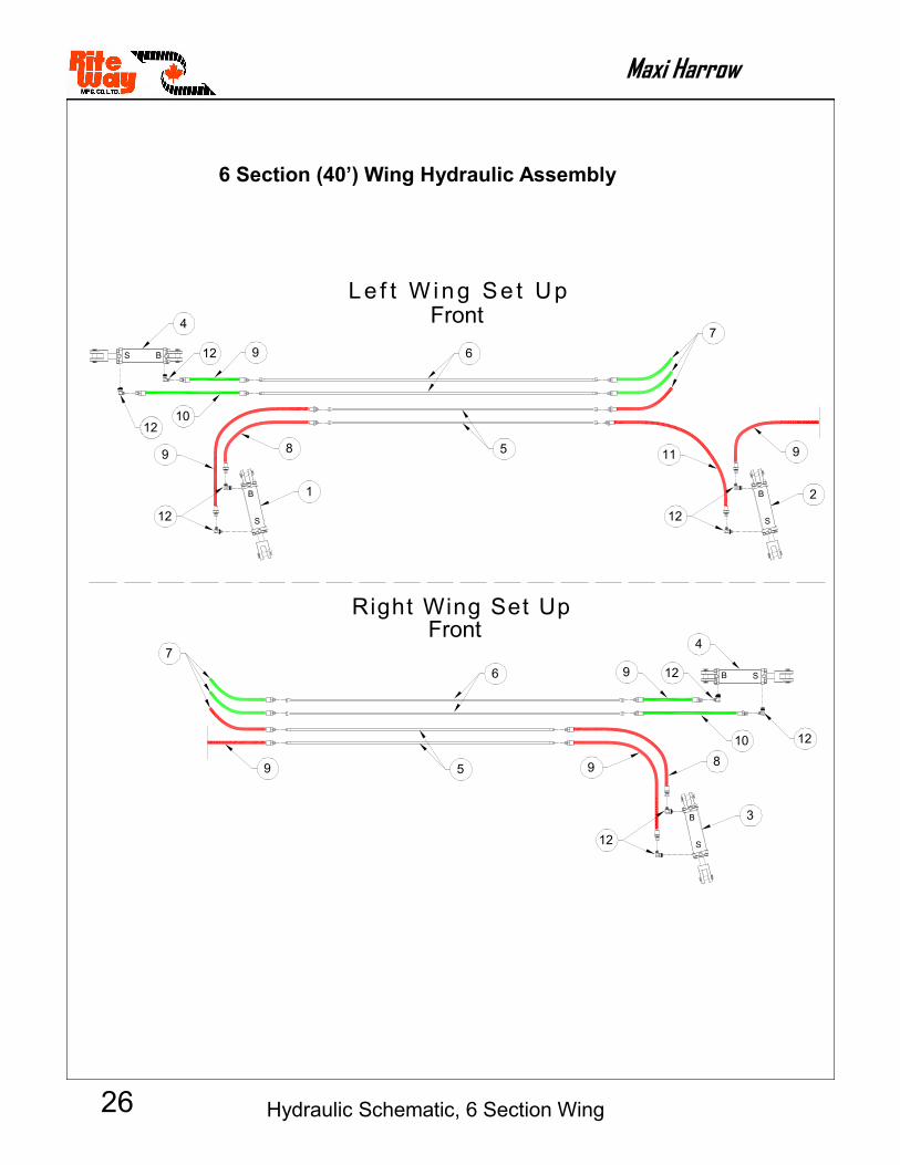
Hydraulic Schematic, 6 Section Wing
6 Section (40’) Wing Hydraulic Assembly

27
Maxi Harrow
Hydraulic Schematic, 6 Section Wing
6 Section (40’) Wing Hydraulic Assembly
Item # Part # Description Quantity
1 030-5735 2-3/4 x 8 - 112 Re-phase Cylinder, 3/4” ORB @ 90° 1
2 030-5736 3 x 8 - 125 Re-phase Cylinder, 3/4” ORB @ 90° 1
3 030-5737 3-1/4 x 8 - 125 Re-phase Cylinder, 3/4” ORB @ 90° 1
4 030-5973 2-1/2 x 12 - 112 Hydraulic Cylinder, 3/4” ORB @ 90° 2
5 311-2066 Hydraulic Steel Line - 66” Straight 4
6 311-2083 Hydraulic Steel Line - 83” Straight 4
7 313-3084 3/8” Hydraulic Hose, 3/8” JIC Male x 3/8” JIC Male - 84”, (on A-Frame)
6
8 313-7823 3/8” Hydraulic Hose, 3/8” JIC Male x 3/8” Sw. Female - 23” 2
9 313-7835 3/8” Hydraulic Hose, 3/8” JIC Male x 3/8” Sw. Female - 35” 5
10 313-7849 3/8” Hydraulic Hose, 3/8” JIC Male x 3/8” Sw. Female - 49” 2
11 313-7991 3/8” Hydraulic Hose, 3/8” JIC Sw. Female x 3/8” Sw. Female - 120”
1
12 319-5710 90° Elbow, 1/2” ORB Male x 3/8” JIC Male 10

28
Maxi Harrow
Hydraulic Schematic, 10 Section Wing
Le
ft W
ing
Se
t U
p
1
6
2
77
7
8
92
0
10
19
11
12
15
14
13
16
17
19
Rig
ht
Win
g S
et
Up
35
6
8
77
72
0
10
19
11
12
17
18
16
13
15
14
19
19
19
4B
S
B
S
B
S
B
S
B
S
BS
BS
9
19
Fro
nt
Fro
nt
10 Section (68’) Wing Hydraulic Assembly

29
Maxi Harrow
Hydraulic Schematic, 10 Section Wing
Item # Part # Description Quantity
1 030-5734 2-1/2 x 8 -112 Re-phase Cylinder, 3/4” ORB @ 90° 1
2 030-5735 2-3/4 x 8 - 112 Re-phase Cylinder, 3/4” ORB @ 90° 1
3 030-5736 3 x 8 - 125 Re-phase Cylinder, 3/4” ORB @ 90° 1
4 030-5737 3-1/4 x 8 - 125 Re-phase Cylinder, 3/4” ORB @ 90° 1
5 030-5738 3-1/2 x 8 - 125 Re-phase Cylinder, 3/4” ORB @ 90° 1
6 030-5974 3 x 8 - 125 Hydraulic Cylinder, 3/4” ORB Ports in line 2
7 311-2083 Hydraulic Steel Line - 83” Straight 14
8 311-2104 Hydraulic Steel Line - 104” Straight 4
9 313-3031 3/8” Hose, 3/8” JIC Male x 3/8” JIC Male - 31” 4
10 313-3084 3/8” Hydraulic Hose, 3/8” JIC Male x 3/8” JIC Male - 84”, (on A-Frame)
6
11 313-7816 3/8” Hydraulic Hose, 3/8” JIC Male x 3/8” Sw. Female - 16” 2
12 313-7823 3/8” Hydraulic Hose, 3/8” JIC Male x 3/8” Sw. Female - 23” 2
13 313-7835 3/8” Hydraulic Hose, 3/8” JIC Male x 3/8” Sw. Female - 35” 2
14 313-7839 3/8” Hydraulic Hose, 3/8” JIC Male x 3/8” Sw. Female - 39” 2
15 313-7849 3/8” Hydraulic Hose, 3/8” JIC Male x 3/8” Sw. Female - 49” 2
16 313-7871 3/8” Hydraulic Hose, 3/8” JIC Male x 3/8” Sw. Female - 71” 2
17 313-7934 3/8” Hydraulic Hose, 3/8” JIC Sw. Female x 3/8” Sw. Female - 34” 1
18 313-7991 3/8” Hydraulic Hose, 3/8” JIC Sw. Female x 3/8” Sw. Female - 120” 1
19 319-5710 90° Elbow, 1/2” ORB Male x 3/8” JIC Male 14
20 324-0031 Nipple, 3/8” JIC Male (x2) 6
10 Section (68’) Wing Hydraulic Assembly
30
Maxi Harrow
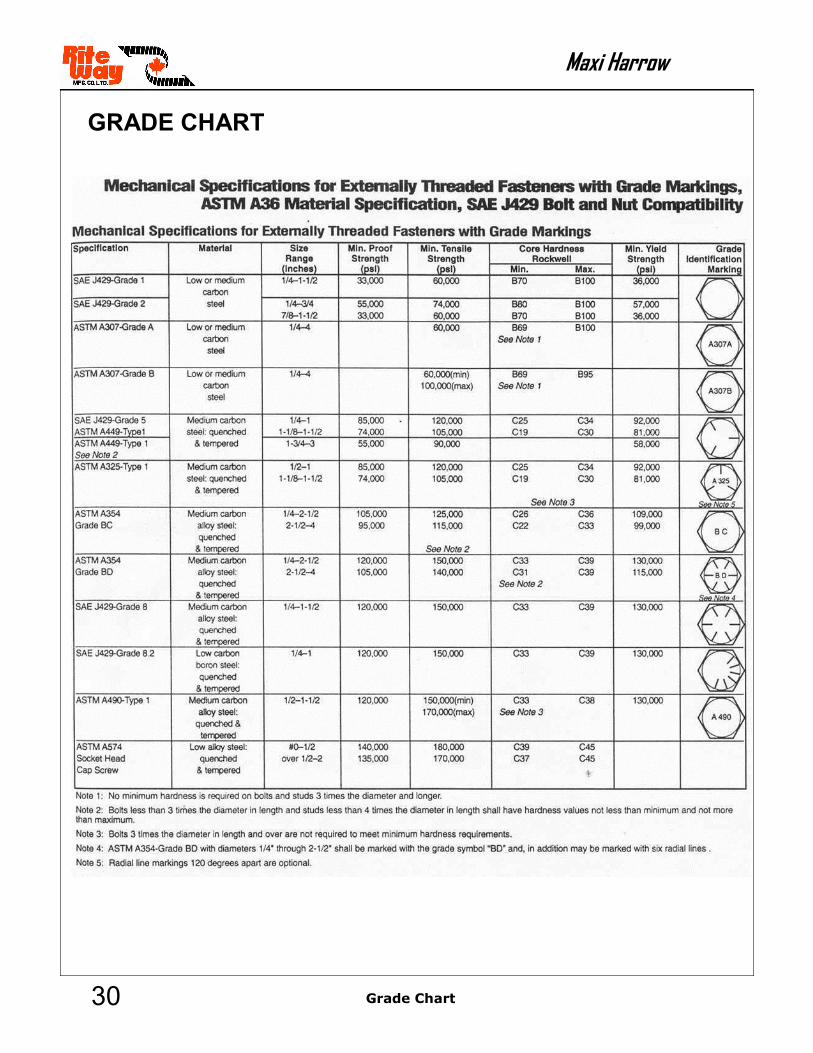
GRADE CHART
Grade Chart

31
Maxi Harrow
TORQUE CHART
Torque Chart

This page is blank intentionally

Maxi Harrow
SECTION 2


01
Maxi Harrow
A-Frame Assembly

02
Maxi Harrow
A-Frame Assembly
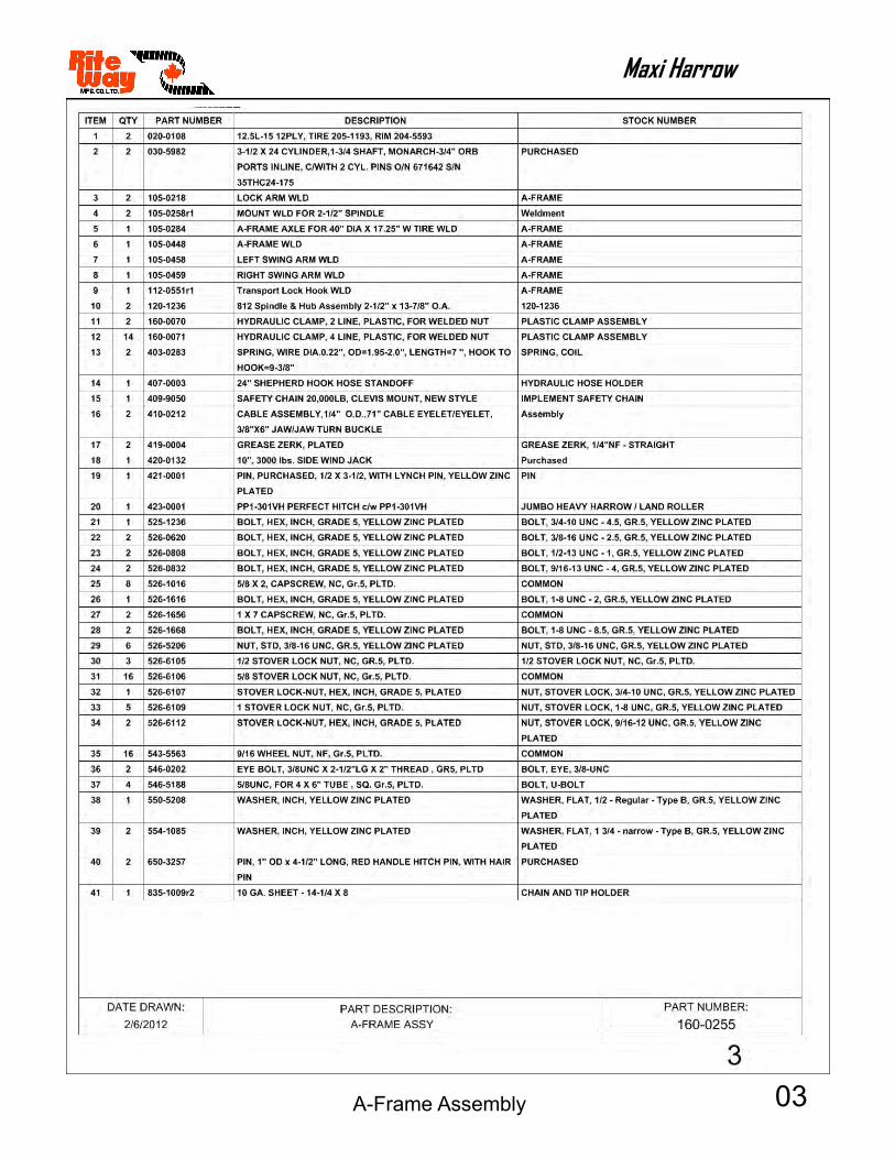
03
Maxi Harrow
A-Frame Assembly

04
Maxi Harrow
Center Bar Assembly
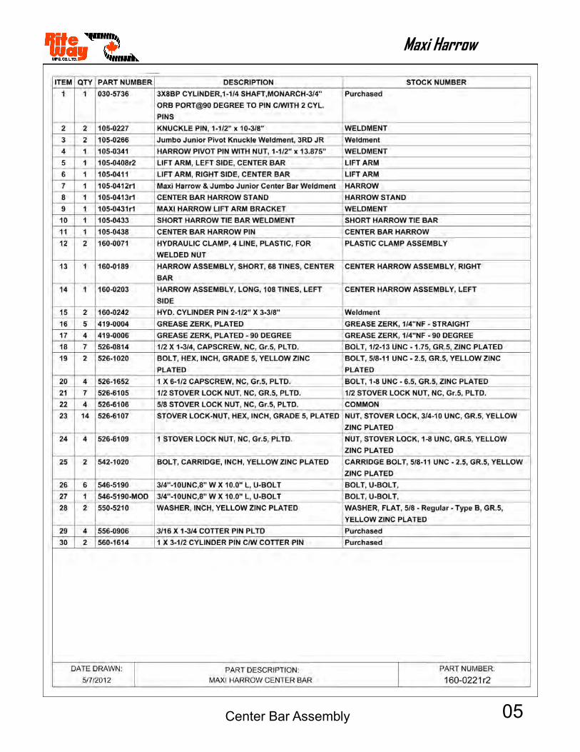
05
Maxi Harrow
Center Bar Assembly

06
Maxi Harrow
Center Bar Assembly

07
Maxi Harrow
Center Bar Assembly
08
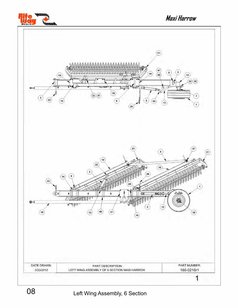
Maxi Harrow
Left Wing Assembly, 6 Section

09
Maxi Harrow
Left Wing Assembly, 6 Section
10
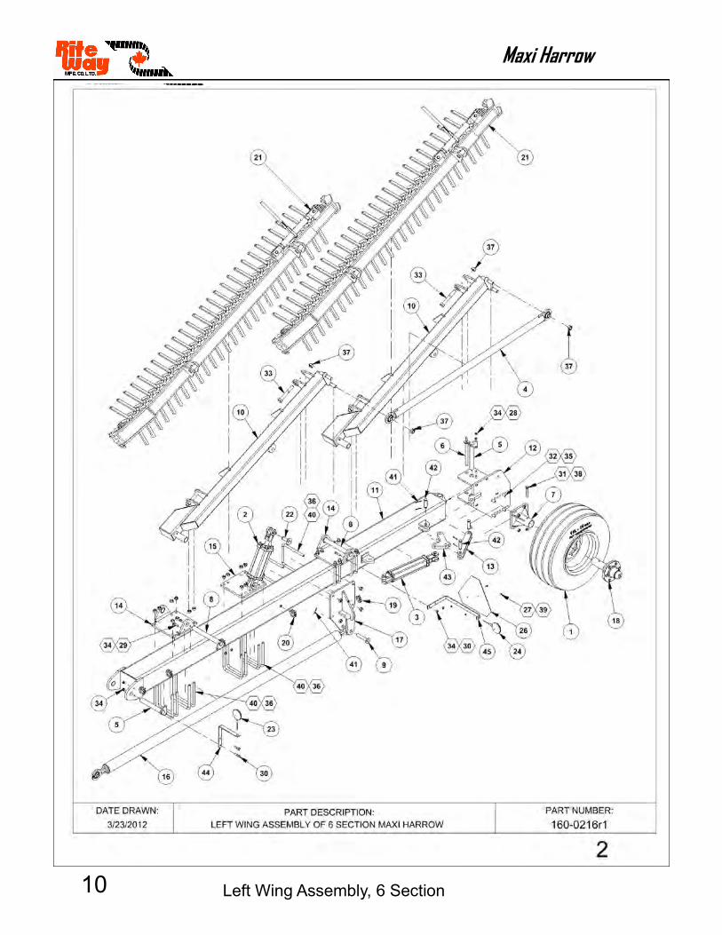
Maxi Harrow
Left Wing Assembly, 6 Section

11
Maxi Harrow
Left Wing Assembly, 6 Section

12
Maxi Harrow
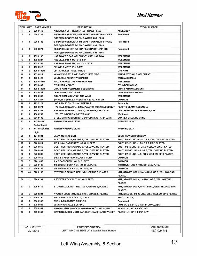
Left Wing Assembly, 8 Section
13
Maxi Harrow
Left Wing Assembly, 8 Section

14
Maxi Harrow
Left Wing Assembly, 8 Section

15
Maxi Harrow
Left Wing Assembly, 8 Section
16
Maxi Harrow
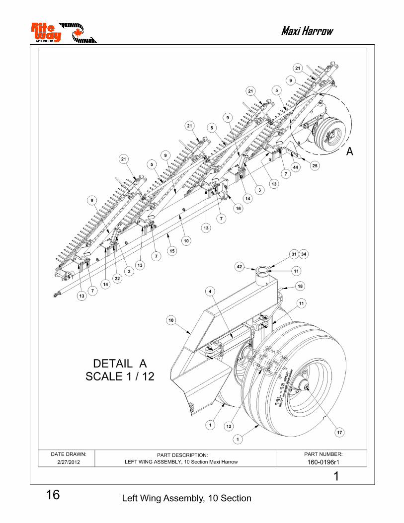
Left Wing Assembly, 10 Section

17
Maxi Harrow
Left Wing Assembly, 10 Section

18
Maxi Harrow
Left Wing Assembly, 10 Section

19
Maxi Harrow
Left Wing Assembly, 10 Section

20
Maxi Harrow
Harrow Assembly, Short, 68 Tines
21
Maxi Harrow
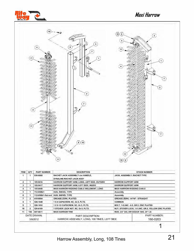
Harrow Assembly, Long, 108 Tines

22
Maxi Harrow
23
Maxi Harrow
24
Maxi Harrow
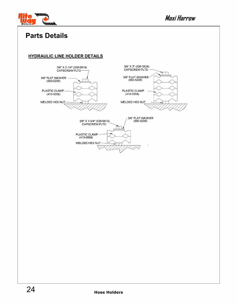
Parts Details
HYDRAULIC LINE HOLDER DETAILS
Hose Holders

25
Maxi Harrow
Perfect Hitch
Parts Details
PERFECT HITCH ASSEMBLY
The purpose of the “Perfect Hitch” is to allow the operator to always use the tractor draw pin and maintain a tight, flexible connection.
The sliding V-block has a polyurethane cushion which is made to flex. The cushion also acts as a shock absorber to reduce driveline stress, giving driveline components longer life. Do not remove all the cushions!
NOTE: INSTALL THE PERFECT HITCH COMPONENTS WITH BOLT HEAD ON THE BOTTOM AND THE TOP PLATE ON TOP.
Always adjust the V-block to your tractor draw pin size by following these steps.
1. Remove top plate by unscrewing ¾” bolt from bottom of Perfect Hitch and lifting top plate.
2. The polyurethane cushion can be laid flat to achieve
an extra ¼” of adjustment.
3. If more closure is needed metal spacers (not supplied) can be placed behind the cushions to push the V-block forward and closer to the draw pin hole to tractor draw pin size. Replace top plate and re-install ¾” bolt tightly (Approx.
200 ft. /lb.).
ITEM # PART # DESCRIPTION
1. 423-0005 BASE HITCH (PP1-301V3)
2. 423-0017 PP1-302V TOP PLATE PERFECT HITCH
3. 423-0018 PP1-203VR V-BLOCK
4. 423-0019 PP1-205H NEOPRENE CUSHION
5. 526-1224 3/4” X 3” CAPSCREW, NC, GR.5,
PLTD.

26
Maxi Harrow
Parts Details
Side Wind Parking Jack
10", 3000 lbs. SIDE WIND JACK PARKING JACK
RITE WAY PART NUMBER 420-0132
ITEM# PART# DESCRIPTION 1. xxx-xxxx Side Wind Crank Kit 2. xxx-xxxx Gear Set 3. xxx-xxxx Hitch Pin c/w Chain 4. xxx-xxxx Screw Replacement 5. xxx-xxxx Inner Ram Assembly 6. xxx-xxxx ¼” x 3” Capscrew, UNC 7. xxx-xxxx ¼” Nylon Lock Nut, UNC 8. xxx-xxxx Cover 9. xxx-xxxx Body
5
4
6
1
28
7
3
9

27
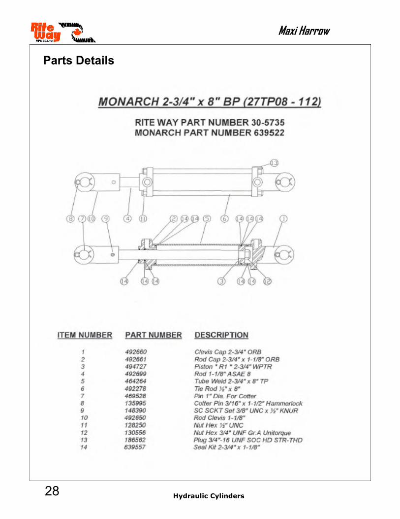
Maxi Harrow
Hydraulic Cylinders
Parts Details
28
Maxi Harrow
Parts Details
Hydraulic Cylinders

29
Maxi Harrow
Parts Details
Hydraulic Cylinders

30
Maxi Harrow
Parts Details
Hydraulic Cylinders

31
Maxi Harrow
Parts Details
Hydraulic Cylinders

32
Maxi Harrow
MONARCH 3-1/2" BORE X 24" STROKE HYDRAULIC CYLINDER
CYLINDER 35THC24-175 (3/4” ORB) RITE WAY PART # 030-5982 MONARCH PART # 648483
ITEM # PART # DESCRIPTION
1 492676 CLEVIS CAP 3.50-3/4ORB-1.00
2 494290 ROD CAP 3.50-1.75-3/4ORB-TS
3 258827 PISTON 3.50-1.000-TSS-ISO-W
4 437243 ROD CYL 1.75-24-1.00-1.50
5 491814 TUBE CYL 3.50-24.00
6 492354 TIE ROD 5/8-24
7 235026 PIN KIT 1.00 C/W COTTER PIN
8 148000 SET SCREW 3/8UNC ONE PIECE
9 493168 ROD CLEVIS 1.50-1.00 SHORT/
10 128271 NUT HEX 5/8-18UNF GRADE5
11 130560 NUT HEX 1-14 LOCK GRB
12 190132 WEAR RING 1.87-1.75-0.250
12 190188 WEAR RING 3.50-3.38-0.250
12 194115 SEAL ZURCON U-CUP RU9 1.75
12 199160 SEAL WIPER 1.75 WNUC TSS
12 197066 SEAL ZURCON WYNSEAL 3.50"-I
12 199141 SEAL DUAL 3.50
Parts Details

33
Maxi Harrow
MONARCH 2-1/2" BORE X 12" STROKE HYDRAULIC CYLINDER
CYLINDER 25TX12-112 (ORB 90 B) RITE WAY PART # 030-5973 MONARCH PART # 648687
ITEM # PART # DESCRIPTION
1 293014 CLEVIS CAP 2.50-3/4ORB-1.00
2 293017 ROD CAP 2.50-1.13-3/4ORB-TX
3 293011 PISTON 2.50-TX
4 497510 ROD CYL 1.12-12-1.00-1.00-T
5 498515 TUBE CYL 2.50-12.00-TX
6 292515 TIE ROD 3/8-12-TX
7 235005 PIN KIT 1.00 C/W COTTER PIN
8 148000 SET SCREW 3/8UNC ONE PIECE
9 293009 ROD CLEVIS 1.00-1.00-TX
10 128230 NUT HEX 3/8UNC GRADE 5
11 186562 FITTING PLUG 3/4-16 ORB SCK
12 194893 SEAL HALLITE 605 ROD 1-1/8
12 197601 O RING 024 1.125X1.225 N90
12 197793 SEAL BU#330 19PI-330
12 198100 O RING 330*DWG*2-1/8X2-1/2
12 198680 O RING 228 2-1/4X2-1/2 DURO
12 199110 SEAL WIPER ROD 1.125 METAL
Parts Details

34
Maxi Harrow
MONARCH 2-1/2" BORE X 12" STROKE HYDRAULIC CYLINDER
CYLINDER 30TX08-125 (ASAE ORB 90 B) RITE WAY PART # 030-5974 MONARCH PART # 648698
ITEM # PART # DESCRIPTION
1 293015 CLEVIS CAP 3.00-3/4ORB-1.00-TX
2 293018 ROD CAP 3.00-1.25-3/4ORB-TX
3 293003 PISTON 3.00-TX
4 497506 ROD CYL 1.25-08-1.13-1.13-T
5 498501 TUBE CYL 3.00-08.00-TX
6 292501 TIE ROD 7/16-08-TX
7 235005 PIN KIT 1.00 C/W COTTER PIN
8 148000 SET SCREW 3/8UNC ONE PIECE
9 293002 ROD CLEVIS 1.13-1.00-TX
10 128500 NUT HEX 7/16-14UNC GRADE
Parts Details

35
Maxi Harrow
LAND ROLLER ACRE METER PLACEMENT
4100 ACRE METER KIT – RITE WAY PART NUMBER SEE BELOW
Note: Serial # required before acre meter can be ordered
TEM# PART# DESCRITION 1. 112-0258 4” ID Acre Meter Housing 2.* 266-0032 Model 4114 Acre Meter 2.* 266-0033 Model 4116 Acre Meter 2.* 266-0034 Model 4118 Acre Meter 2.* 266-0013 Model 4120 Acre Meter 3. 518-0808 ½” x ½” Set Screw, NC, Black 4. 526-0832 ½” x 4” Capscrew, NC, Gr. 5, Pltd. 5. 526-7008 ½” Nylon Lock Nut, NC, Gr.5, Pltd. 6. 525-6108 ½” Jam Nut, NC, Gr.5, Pltd. 7. 550-5208 ½” B.S. Plate Washer, Pltd. 8. 807-4203 2-7/16” x 16-1/2” Replaceable Drum Shaft
NOTE: Use Loc-Tite with jam nut when assembling to housing. DO NOT OVER TIGHTEN.

NOTES