mcas cherry point course rules briefcherrypointatc.com/atcweb/nkt course rules 150129.pdfcourse...
TRANSCRIPT
MCAS Cherry Point Course Rules Brief
121024

Course Rules Brief Requirement
• All pilots and NFOs shall receive an MCAS Cherry Point course rules brief prior to conducting flight operations from MCAS Cherry Point.
• Pilots and NFOs assigned to MCAS Cherry Point shall receive an initial course rules brief and annually thereafter when participating in Instrument Ground School.
• Airfield Operations Officer
- (252) 466-6327
• Air Traffic Control Facility Officer
- (252) 466-4664
Points of Contact

Sources
• Airfield Operations Manual (ASO 3710.5k)
• Cherry Point ATC Facility Manual
• FAA JO 7110.65
• www.cherrypointatc.com

Overview
• Airfield Layout
• Taxi / Ground Procedures
• Departure Procedures
• Traffic Patterns
• VFR Entry / Exit Routes
• SVFR Requirements
• Noise Abatement
• Planned Ejection
• Ordnance Jettison
• NORDO Procedures
• Fueling / Fuel Dumping
• Hot Brakes
• Arrival Procedures
• Radar Services
• Special Use Airspace
Airfield Layout

N 34 54.3 W 076 53.4 29’ MSL
8000’ x 200’(15,525’) 75X
E-28

Runway Information
• Runway 32L / 14R
Length / Width 8399 x 200
Magnetic Hdg 325 / 145
TZE Rwy 32L – 17’
• Runway 32R / 14L
Length / Width 8984 x 200
Magnetic Hdg 325 / 145
TZE Rwy 14L – 19’
• Runway 5L / 23R
Length / Width 7553 x 200
Magnetic Hdg 055 / 235
TZE Rwy 23R – 19’
• Runway 5R / 23L
Length / Width 8188 x 200
Magnetic Hdg 055 / 235
TZE Rwy 5R – 23’
-Rwy 5R will not be the duty unless wind
is > 10kts sustained
-Rwy 32L is the calm wind/instrument rwy

Airfield Diagram
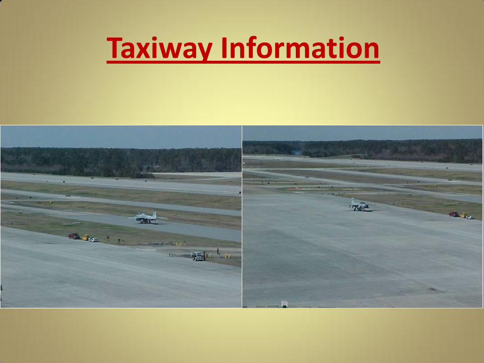
Taxiway Information
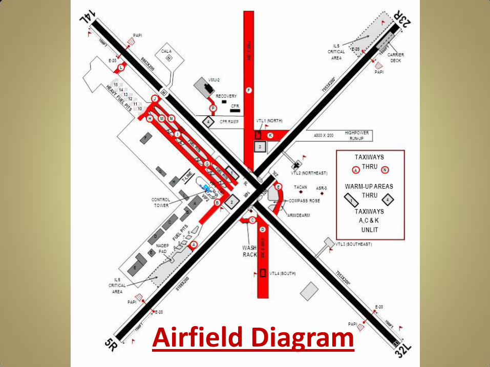
Airfield Diagram
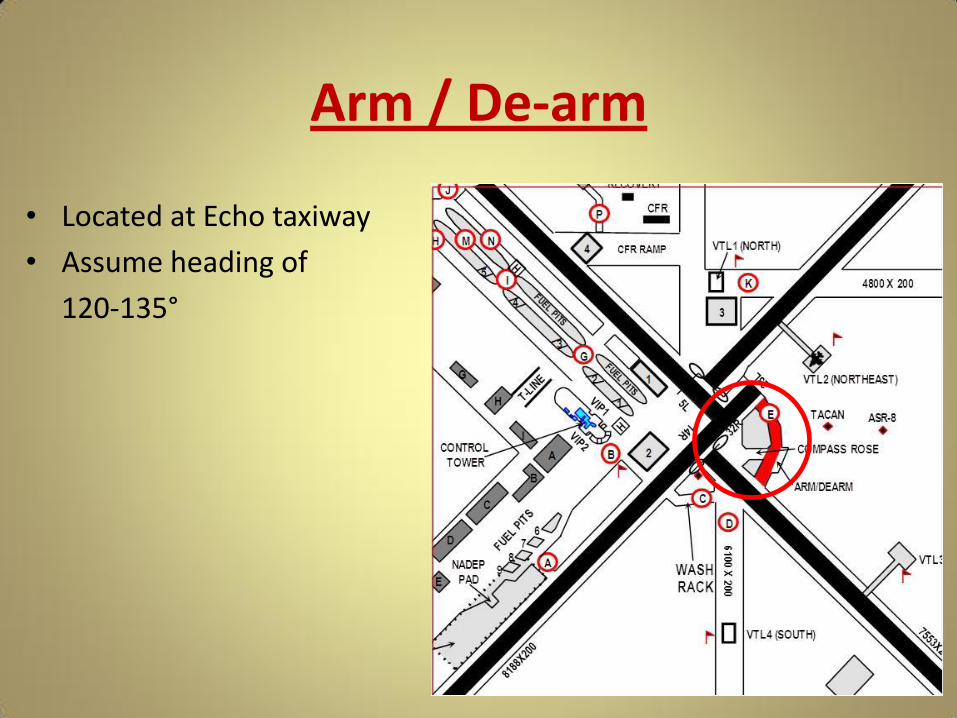
Arm / De-arm
• Located at Echo taxiway
• Assume heading of
120-135°
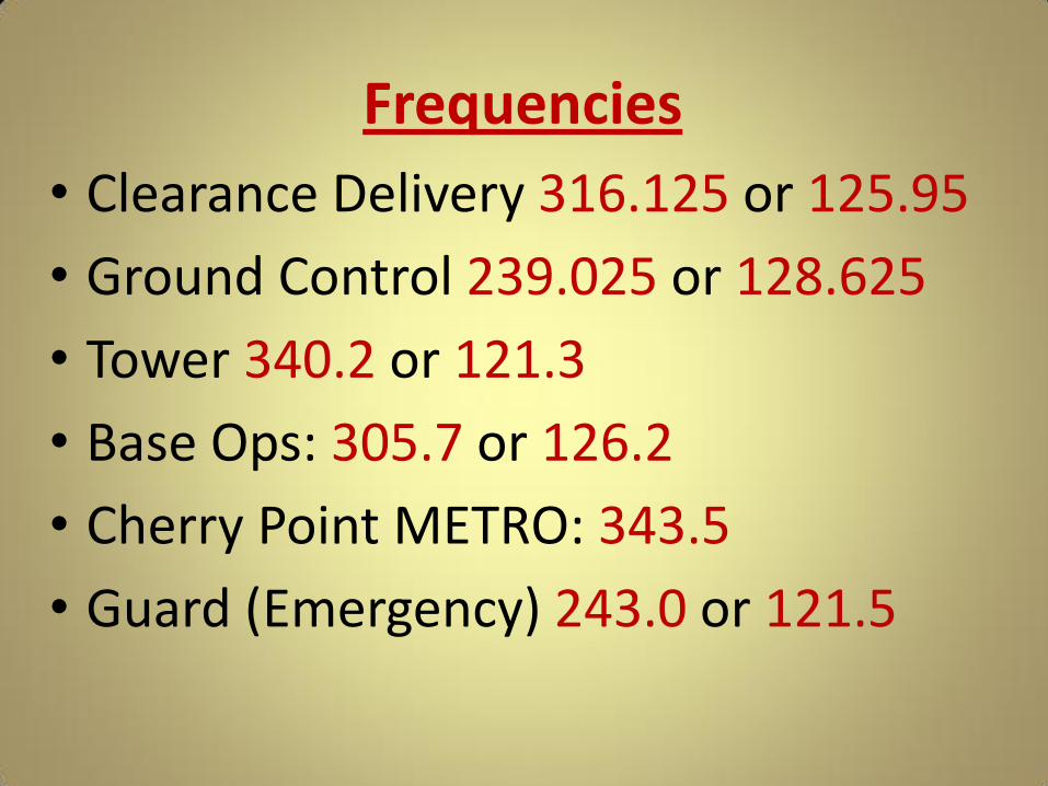
Frequencies
• Clearance Delivery 316.125 or 125.95
• Ground Control 239.025 or 128.625
• Tower 340.2 or 121.3
• Base Ops: 305.7 or 126.2
• Cherry Point METRO: 343.5
• Guard (Emergency) 243.0 or 121.5
• Report current ATIS code on initial contact
• Advise if ATIS is unreadable
(UHF 244.875 / VHF 127.475)
ATIS
Ground Procedures
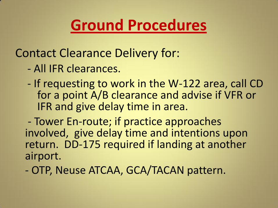
Contact Clearance Delivery for: - All IFR clearances.
- If requesting to work in the W-122 area, call CD for a point A/B clearance and advise if VFR or IFR and give delay time in area.
- Tower En-route; if practice approaches involved, give delay time and intentions upon return. DD-175 required if landing at another airport.
- OTP, Neuse ATCAA, GCA/TACAN pattern.

• If VFR, flight following is preferred
• Clearance required NET 15 min prior to departure
• VFR to R5306: Contact Departure Control prior to taxi with mission number for squawk
Ground Procedures

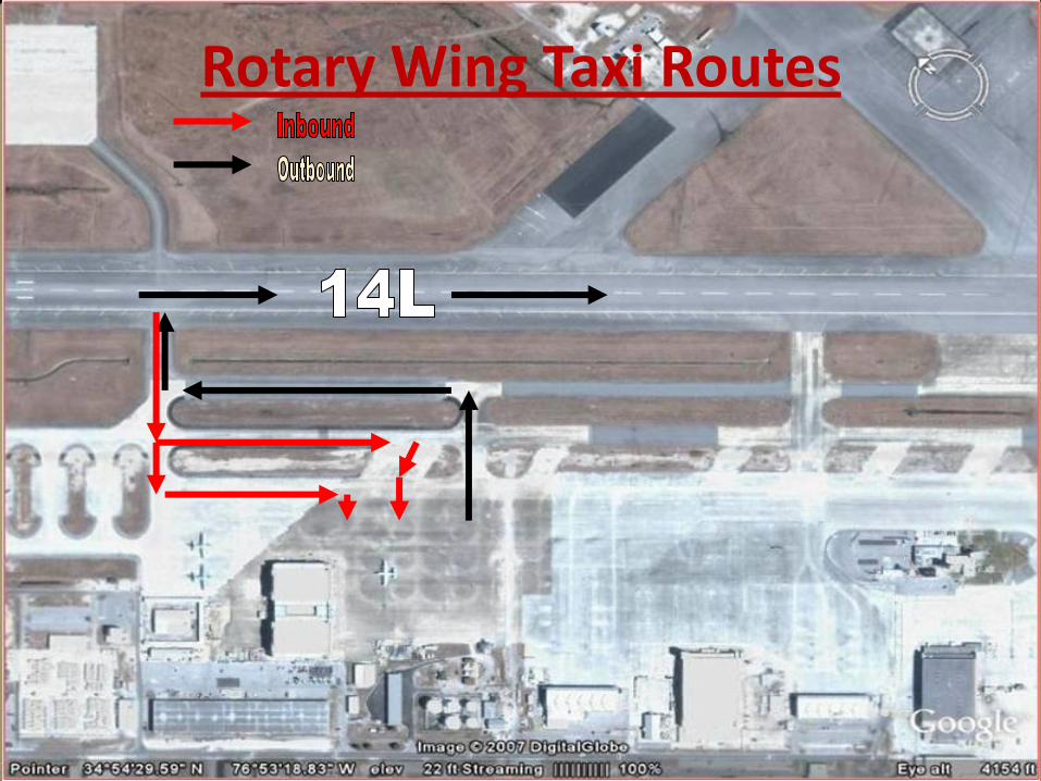
Ground Procedures Taxiway Usage • November taxiway, preferred use is for outbound taxiing aircraft. • Mike taxiway, preferred use is for inbound taxiing aircraft and fuel pit
transitioning.
• Hotel taxiway, used for outbound aircraft, inbound aircraft, and pit transitioning.
• Golf taxiway, preferred use is for F/W transition to November taxiway. • India taxiway, preferred use is for R/W pit transitioning into pits 4/5 and
outbound taxiing aircraft. • Juliet taxiway, preferred use is for R/W transitioning to/from runway 14L
landing area and pit transitioning.
Rotary Wing Taxi Routes
Ground Procedures
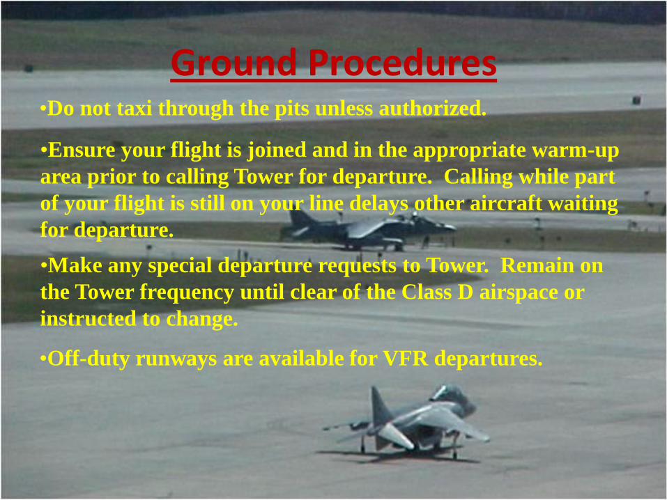
•Ensure your flight is joined and in the appropriate warm-up
area prior to calling Tower for departure. Calling while part
of your flight is still on your line delays other aircraft waiting
for departure.
•Make any special departure requests to Tower. Remain on
the Tower frequency until clear of the Class D airspace or
instructed to change.
•Off-duty runways are available for VFR departures.
•Do not taxi through the pits unless authorized.
Departure Procedures
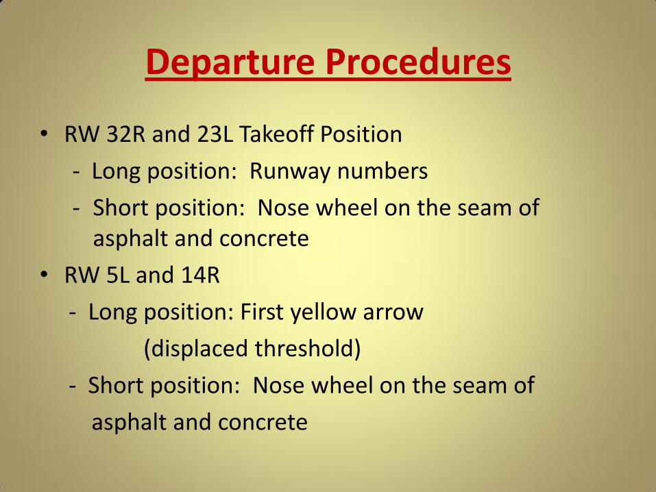
• RW 32R and 23L Takeoff Position
- Long position: Runway numbers
- Short position: Nose wheel on the seam of asphalt and concrete
• RW 5L and 14R
- Long position: First yellow arrow
(displaced threshold)
- Short position: Nose wheel on the seam of
asphalt and concrete

Departure Procedures
• All tactical jet aircraft will depart from the concrete portion of the center-mat with the exception of multiple ship AV8 departures
• VFR Departures
- Maintain 500’ or less until clear of VFR traffic pattern
- Avoid rifle range, Crash Crew, radar site, industrial complex, staff or officer housing
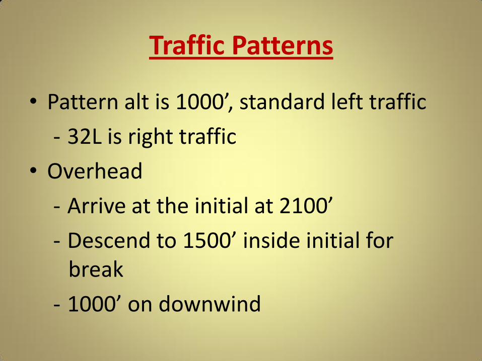
Traffic Patterns
• Pattern alt is 1000’, standard left traffic
- 32L is right traffic
• Overhead
- Arrive at the initial at 2100’
- Descend to 1500’ inside initial for break
- 1000’ on downwind

Traffic Patterns 6 NM
6 NM 6 NM
NKT 061/6
Tower calls break
Expect approach end
5R midfield
Speed < 250 unless required
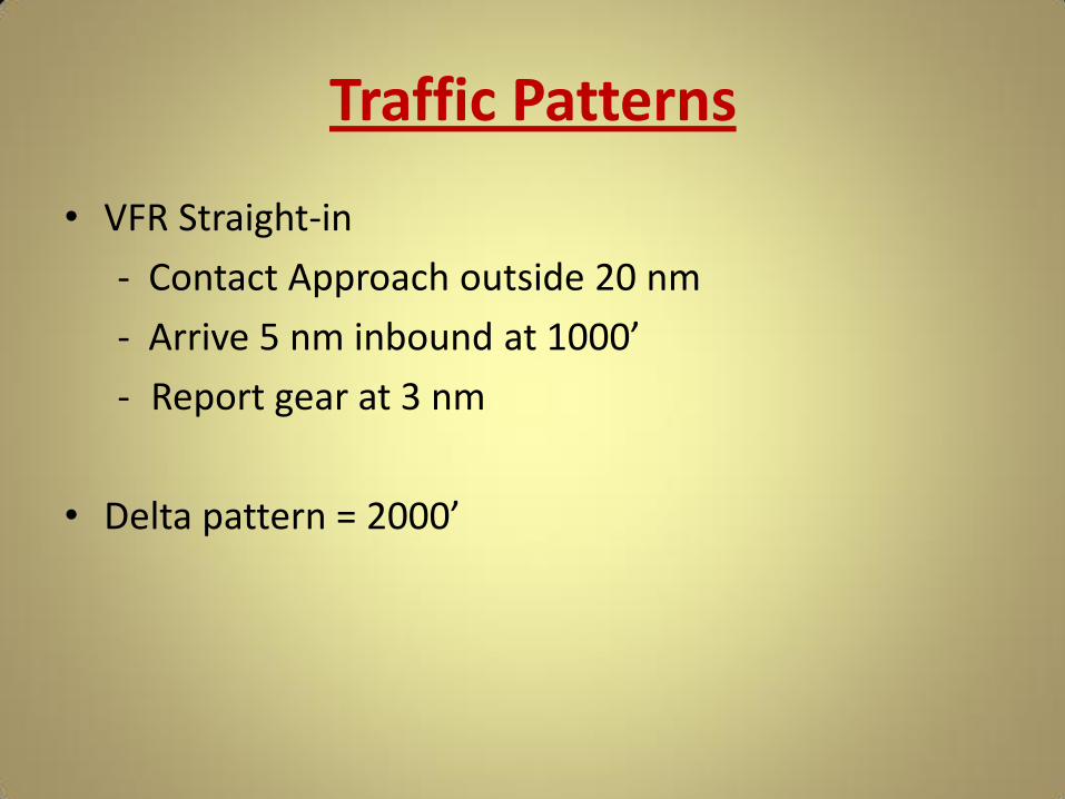
Traffic Patterns
• VFR Straight-in
- Contact Approach outside 20 nm
- Arrive 5 nm inbound at 1000’
- Report gear at 3 nm
• Delta pattern = 2000’

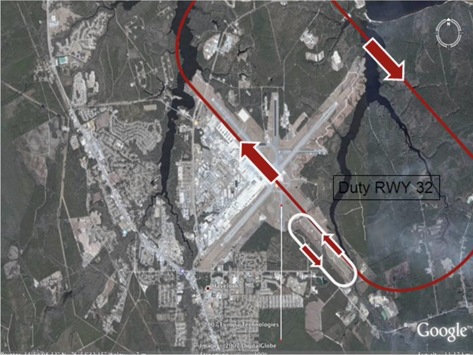
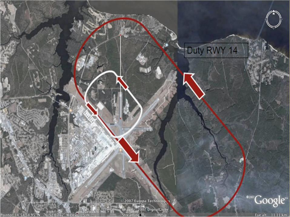
R/W PATTERN vs. F/W PATTERN
• Helicopter tower pattern altitude is 500’. • Helo operations, when duty RWY 14, are at the Tower
Supervisors discretion.
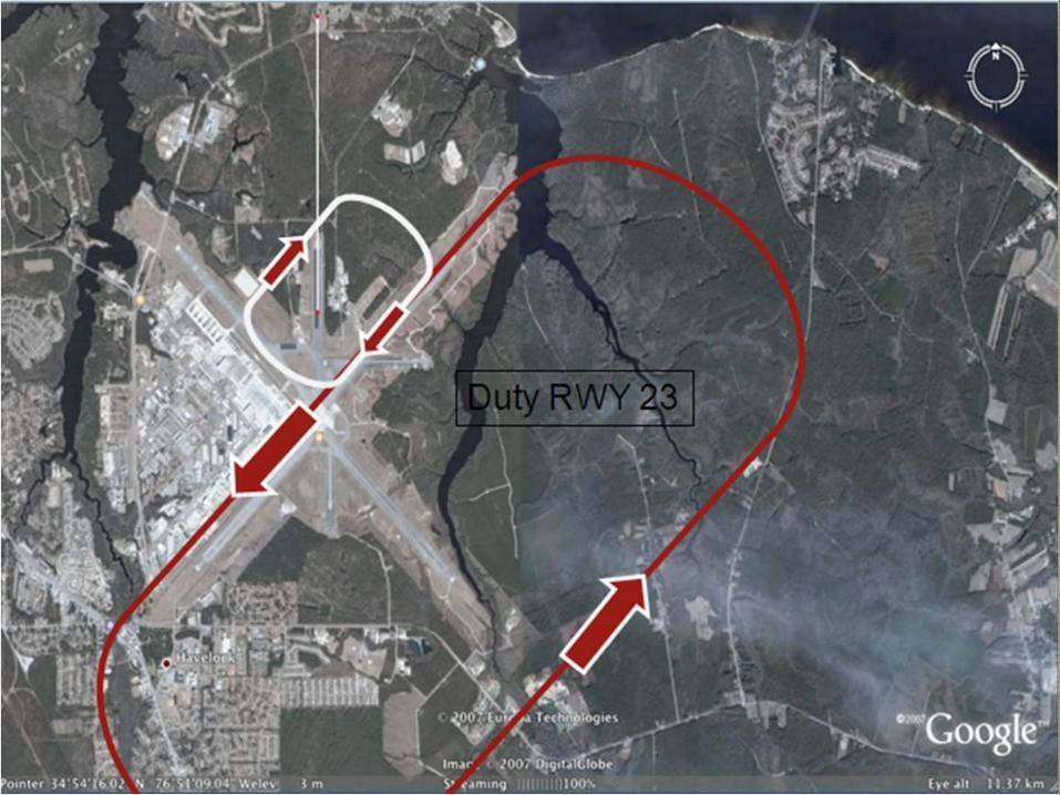
• Patterns for RWY 23 and RWY 14 are wider to avoid over flying CFR and rifle range.
• First choice place for helicopter tower pattern operations is on
an off-duty runway. If the crosswind prevents that from happening and they have to be conducted on the duty runway, the following slides show the downwind pattern de-conflicting with fixed wing traffic:
Traffic Patterns
Traffic Patterns

Traffic Patterns
Traffic Patterns

Off-Duty Runway Helicopter Pattern Characteristics
• Helicopter will land and depart away from the centermat.
• Base shall be turned prior to the 3000 foot remaining board (to keep away from the centermat traffic).
• Left or right downwind will be at the discretion of the Tower Supervisor.
• Be advised on our off-duty runways and the departing runway our E-28 arresting gear will be in battery.

Off-Duty RWY Helicopter Pattern Example
VFR Entry/Exit Routes
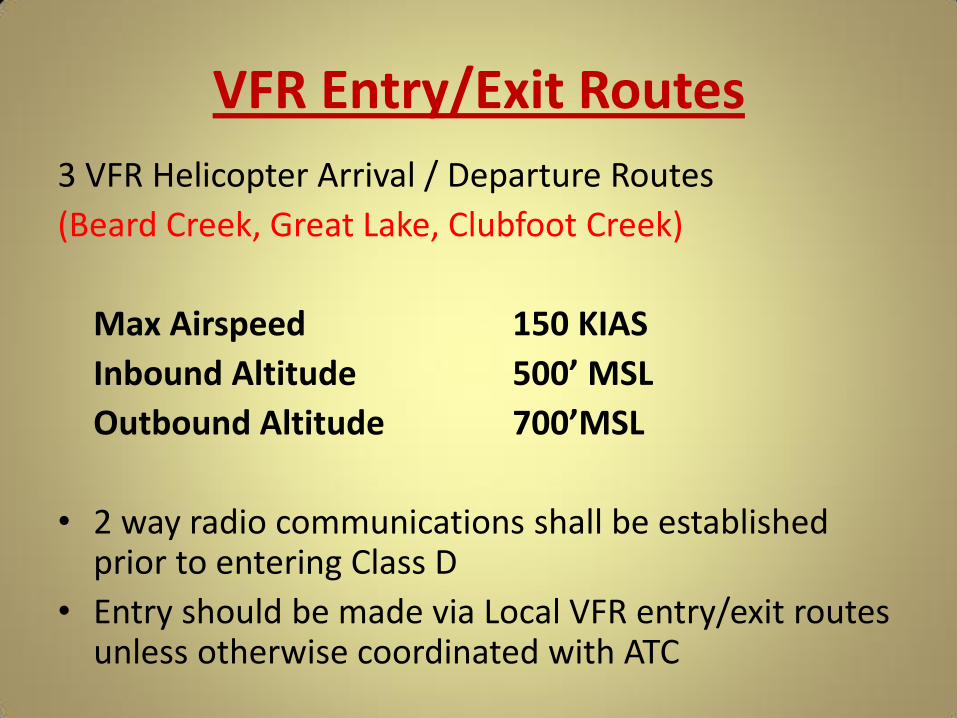
3 VFR Helicopter Arrival / Departure Routes
(Beard Creek, Great Lake, Clubfoot Creek)
Max Airspeed 150 KIAS
Inbound Altitude 500’ MSL
Outbound Altitude 700’MSL
• 2 way radio communications shall be established prior to entering Class D
• Entry should be made via Local VFR entry/exit routes unless otherwise coordinated with ATC

VFR Entry/Exit Routes
VFR Entry/Exit Routes
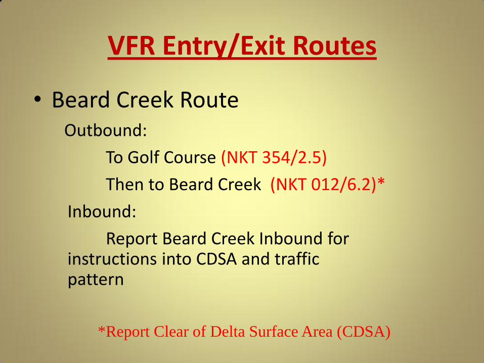
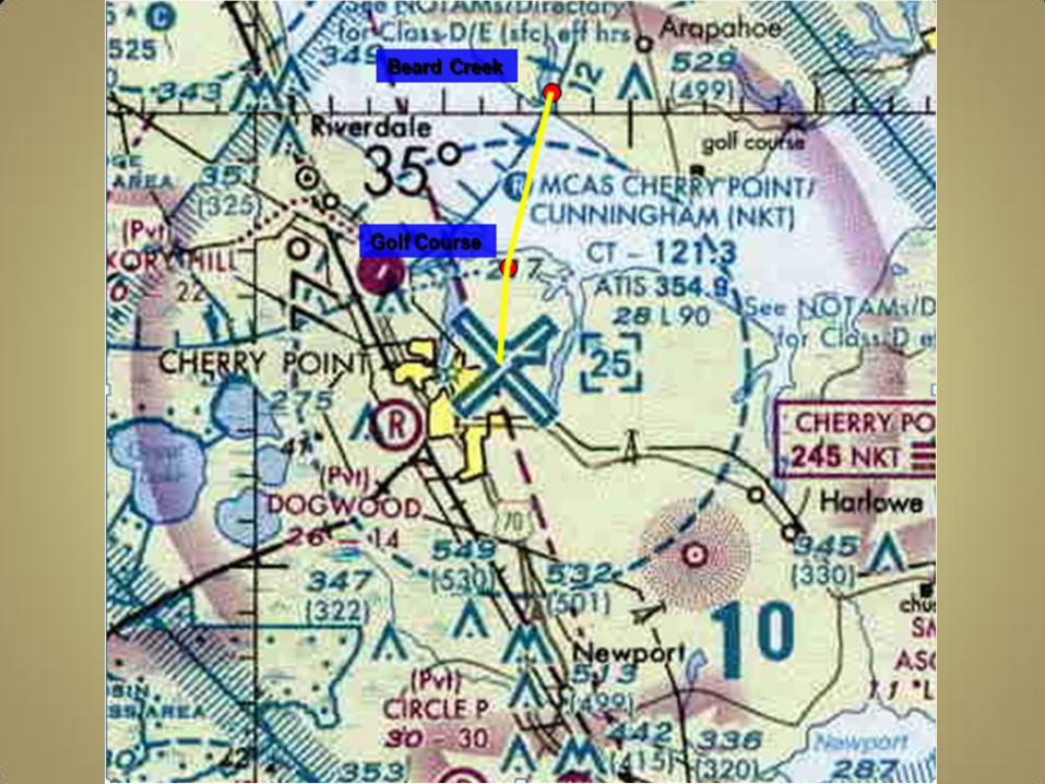
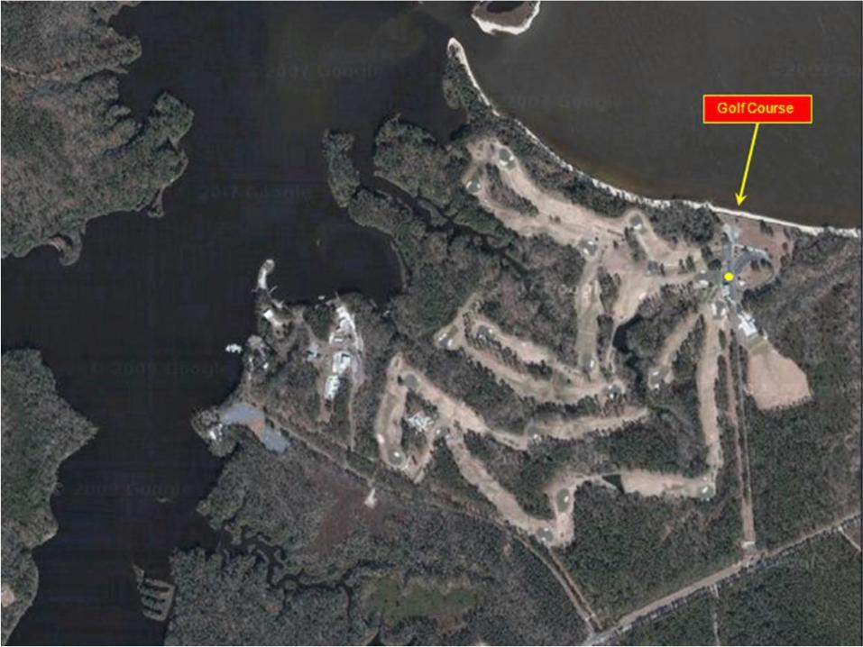
• Beard Creek Route Outbound:
To Golf Course (NKT 354/2.5)
Then to Beard Creek (NKT 012/6.2)*
Inbound:
Report Beard Creek Inbound for instructions into CDSA and traffic pattern
*Report Clear of Delta Surface Area (CDSA)
VFR Entry/Exit Routes
VFR Entry/Exit Routes

VFR Entry/Exit Routes

VFR Entry/Exit Routes
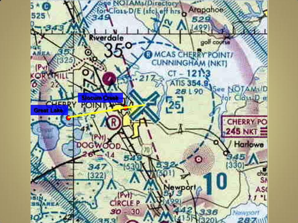
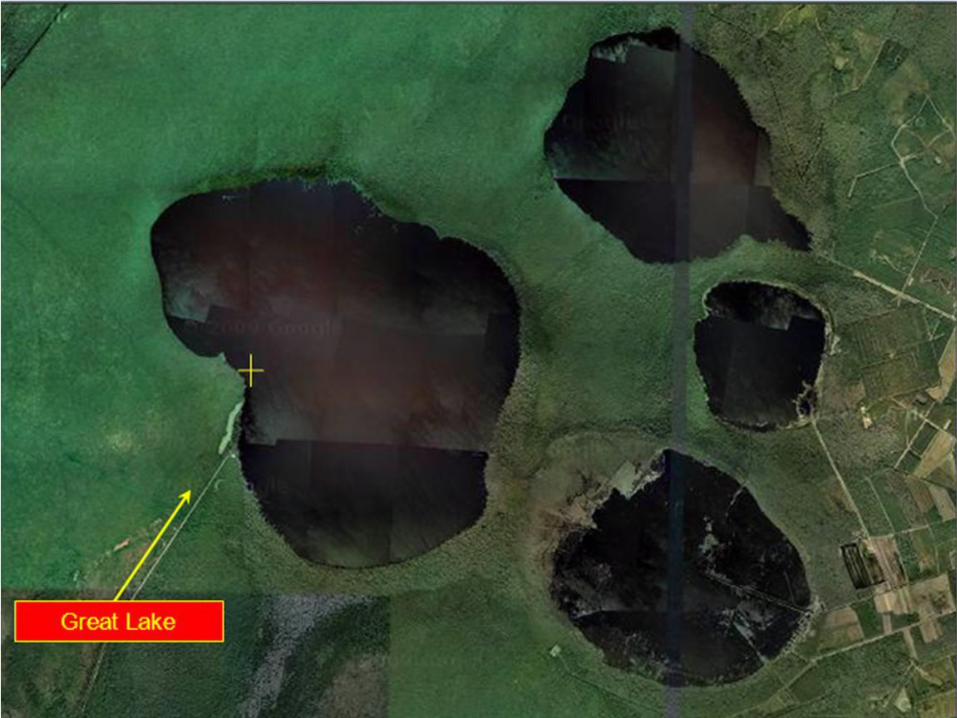
• Great Lake Route Outbound:
To Slocum Creek Bridge (NKT 280/2.1)
Then to Great Lake (NKT 273/7.0)*
Inbound:
The Inbound is the Opposite
*Report Clear of Delta Surface Area (CDSA)
VFR Entry/Exit Routes

VFR Entry/Exit Routes
VFR Entry/Exit Routes

VFR Entry/Exit Routes
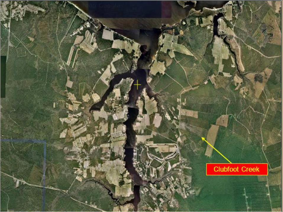
• Clubfoot Creek Route Outbound:
To Hancock Island (NKT 085/1.8)
Then to Clubfoot Creek (NKT 098/5.2)*
Inbound:
The Inbound is the Opposite
*Report Clear of Delta Surface Area (CDSA)

VFR Entry/Exit Routes

VFR Entry/Exit Routes
VFR Entry/Exit Routes
SVFR Requirements
• SVFR operations are authorized for fixed wing aircraft.
• SVFR operations are authorized for rotary wing aircraft.
• Minimum ceiling/visibility authorized for SVFR operations is 500/1SM and aircraft must be able to remain clear of clouds within the Class D surface area.
• Must be requested by the pilot.

SVFR Requirements
• SVFR Clearance from ATC required • All 3 VFR Helicopter routes are authorized for
SVFR flight: – Beard Creek – Great Lake – Clubfoot Creek
• Pilot shall initiate request for SVFR flight and pilots shall report both reporting points either inbound or outbound.
• During SVFR only 1 aircraft is authorized within the CDSA.
Noise Abatement
• Overheads, T&G’s, and low approaches 0700-2300L
• High Power Run-Ups
- 0700-2200L Mon-Sat
- 1300-2200L Sun
- Do not exceed 75% on the line
- Do not exceed 80% in the warm-up areas
*High powers not authorized on RWY 5L or 14R except for departing aircraft
Noise Abatement
• Noise Sensitive Areas (<pattern alt)
- MCAS industrial complex
- Densely populated areas
- Crash Crew
- Rifle Range
- Havelock
- Minnesott Beach
- Cedar Island Ferry Terminal & ferry

NOISE ABATEMENT

NOISE ABATEMENT
Planned Ejection
• If ejection is necessary, and sufficient time/control exists:
–Proceed to BT-11, NKT 078/22
–Fly heading 065 deg

Ordnance Jettison
• The primary authorized ordnance jettison area in the Cherry Point operating area is BT-9, NKT 057/28.5.
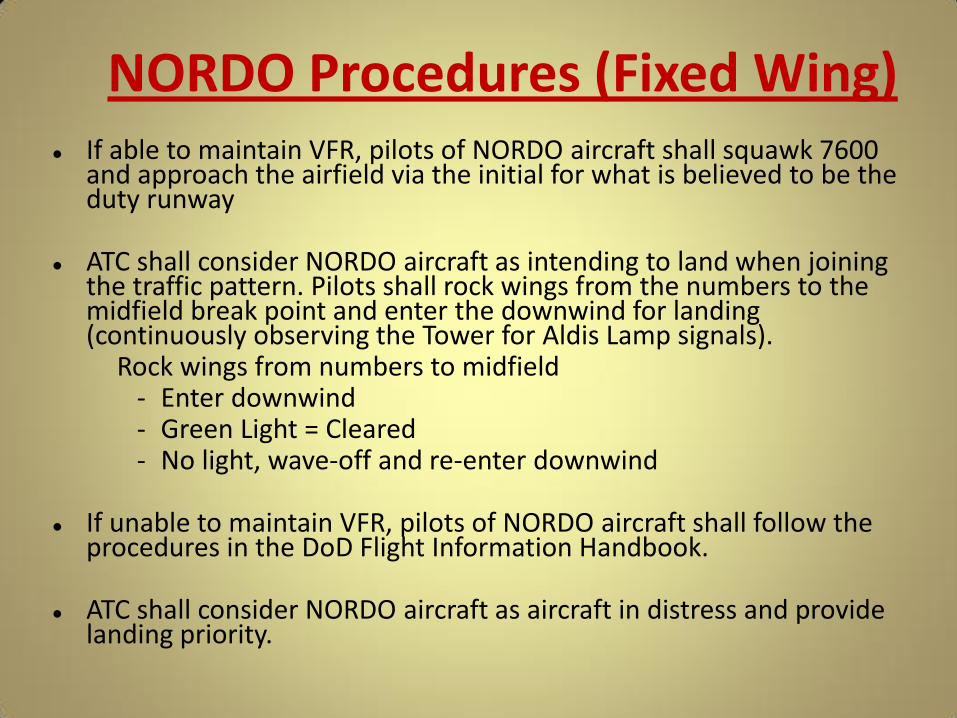
NORDO Procedures (Fixed Wing) If able to maintain VFR, pilots of NORDO aircraft shall squawk 7600
and approach the airfield via the initial for what is believed to be the duty runway
ATC shall consider NORDO aircraft as intending to land when joining the traffic pattern. Pilots shall rock wings from the numbers to the midfield break point and enter the downwind for landing (continuously observing the Tower for Aldis Lamp signals).
Rock wings from numbers to midfield - Enter downwind - Green Light = Cleared - No light, wave-off and re-enter downwind
If unable to maintain VFR, pilots of NORDO aircraft shall follow the
procedures in the DoD Flight Information Handbook. ATC shall consider NORDO aircraft as aircraft in distress and provide
landing priority.
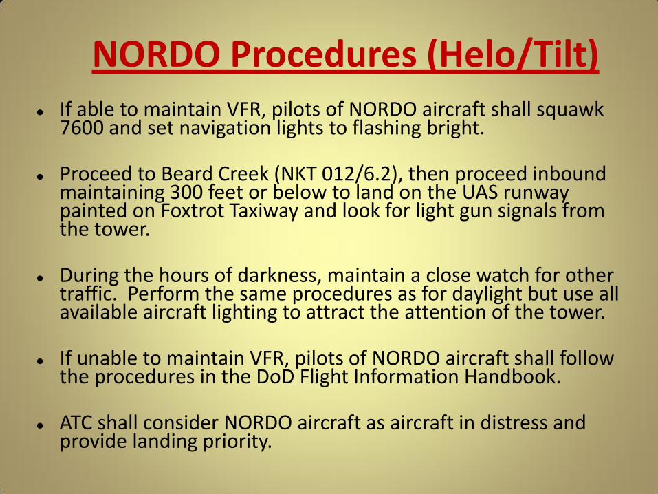
NORDO Procedures (Helo/Tilt) If able to maintain VFR, pilots of NORDO aircraft shall squawk
7600 and set navigation lights to flashing bright.
Proceed to Beard Creek (NKT 012/6.2), then proceed inbound maintaining 300 feet or below to land on the UAS runway painted on Foxtrot Taxiway and look for light gun signals from the tower.
During the hours of darkness, maintain a close watch for other traffic. Perform the same procedures as for daylight but use all available aircraft lighting to attract the attention of the tower.
If unable to maintain VFR, pilots of NORDO aircraft shall follow
the procedures in the DoD Flight Information Handbook. ATC shall consider NORDO aircraft as aircraft in distress and
provide landing priority.

Fueling / Fuel Dumping
• Refueling
-Shall not be done when lightning observed within 5 nm of airfield
-Hot pits not permitted with flares
• Fuel Dumping
-None below 6000’ AGL
-If necessary, avoid populated areas
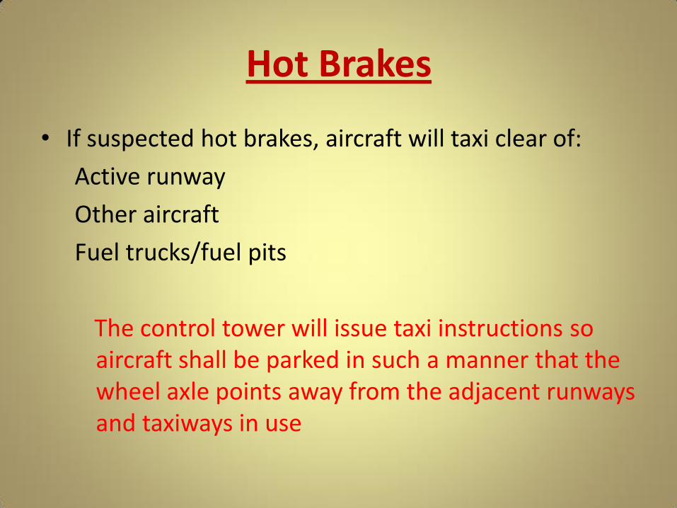
Hot Brakes
• If suspected hot brakes, aircraft will taxi clear of:
Active runway
Other aircraft
Fuel trucks/fuel pits
The control tower will issue taxi instructions so aircraft shall be parked in such a manner that the wheel axle points away from the adjacent runways and taxiways in use

Arrival Procedures
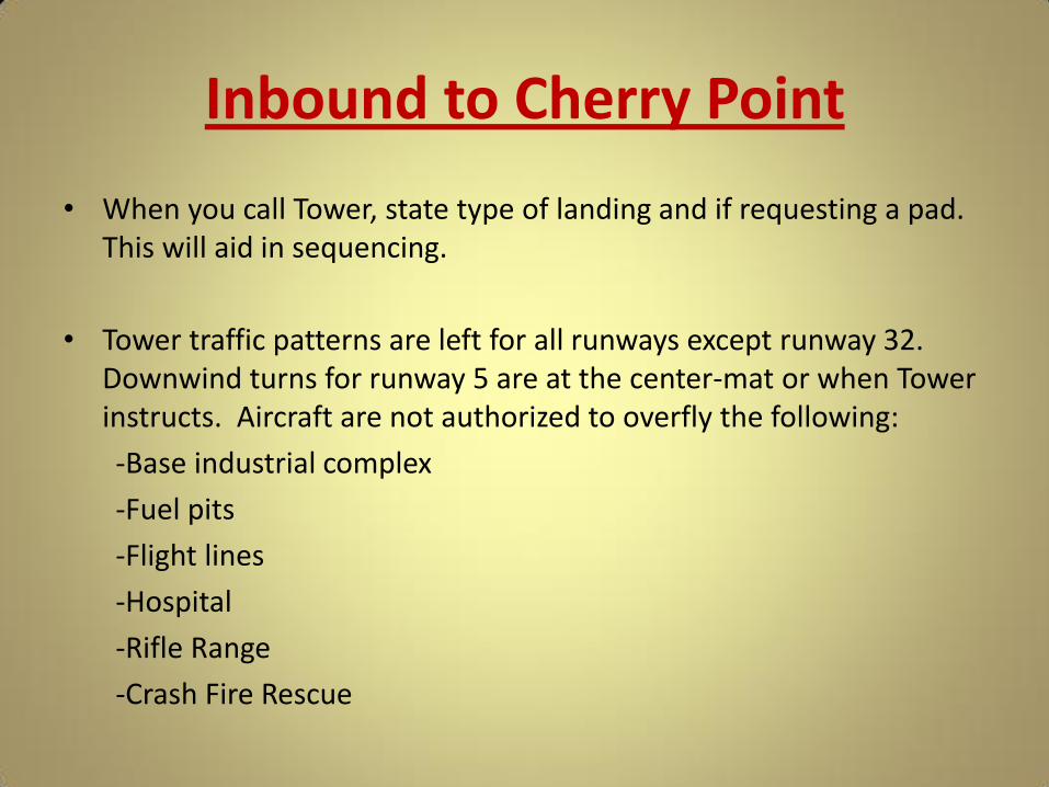
Inbound to Cherry Point
• When you call Tower, state type of landing and if requesting a pad. This will aid in sequencing.
• Tower traffic patterns are left for all runways except runway 32. Downwind turns for runway 5 are at the center-mat or when Tower instructs. Aircraft are not authorized to overfly the following:
-Base industrial complex
-Fuel pits
-Flight lines
-Hospital
-Rifle Range
-Crash Fire Rescue

Instrument Approaches • Precision Approaches
– PAR Rwy 32L, 14L, 5R, 23R – ILS Rwy 23R
• Non-Precision Approaches – TACAN Rwy 14L, 5R, 32L (NKT TACAN Ch 75) Copter TACAN 23R (NOT AUTHORIZED FOR TILTROTOR
A/C) – Surveillance Approaches to runway 32L, 14L, 5R, 23R – RNAV Rwy 23R, 5R, 32L
• Circle to land available on all non-precision approaches and ILS

CALA
DD
FF
BB
AA
ORDNANCE
SAFETY AREA
4
RECOVERY
E-28
E-28
E-28
E-28
PAPI
PAPI
FUEL PITS
JJ
II
GG
EE
5R
32L
23R
14L
8188
X 1
96
8398 X 200*
8491
X 2
00*
8983 X 200
PAPI
PAPI
FUEL PITS
A
B
C
D
E
E
F
G
H
I
KK
CC
VTL4
(SOUTH)NADEP
PAD
BASE OPS /
PASSENGER
TERMINAL /
TOWER
CRASH
CREW
VTL3
(SOUTHEAST)
COMPASS
ROSE
VTL2
(NORTHEAST)
LL
VTL1
(NORTH)
H
HH MM NN
*LANDING DISTANCE 7553’
*LANDING DISTANCE 7607’
AERIAL
PORT OF
EMBARK-
ATIONLARGE
AIRCRAFT
REFUELING
AREA
HANGARS
ELEV
23
055.
2o
235.
2o
ELEV
2832
R14R
23L
5L
FIELD
ELEV
29
HIGH POWER
055.
2o
235.
2o
145.2 o
325.2 o
145.2 o
325.2 o
RADAR REFLECTORS
ON ALL RWYS
CAUTION:
Rwy 32L ldg 7607’
Rwy 23R ldg 7553’
1000 x 500
1000
x 5
00
550 x 500
1700
x 5
00ELEV
17
ELEV
19
ELEV
19
ELEV
29
ELEV
29
CONTACT APPROACH TO A PAD
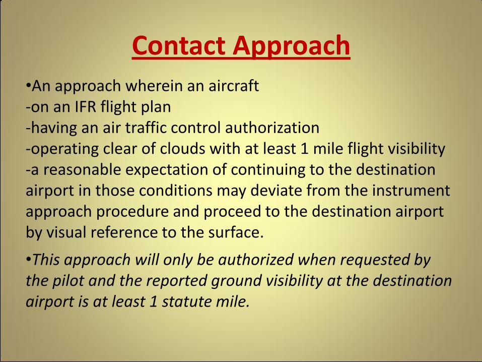
•An approach wherein an aircraft -on an IFR flight plan -having an air traffic control authorization -operating clear of clouds with at least 1 mile flight visibility -a reasonable expectation of continuing to the destination airport in those conditions may deviate from the instrument approach procedure and proceed to the destination airport by visual reference to the surface.
•This approach will only be authorized when requested by the pilot and the reported ground visibility at the destination airport is at least 1 statute mile.
Contact Approach
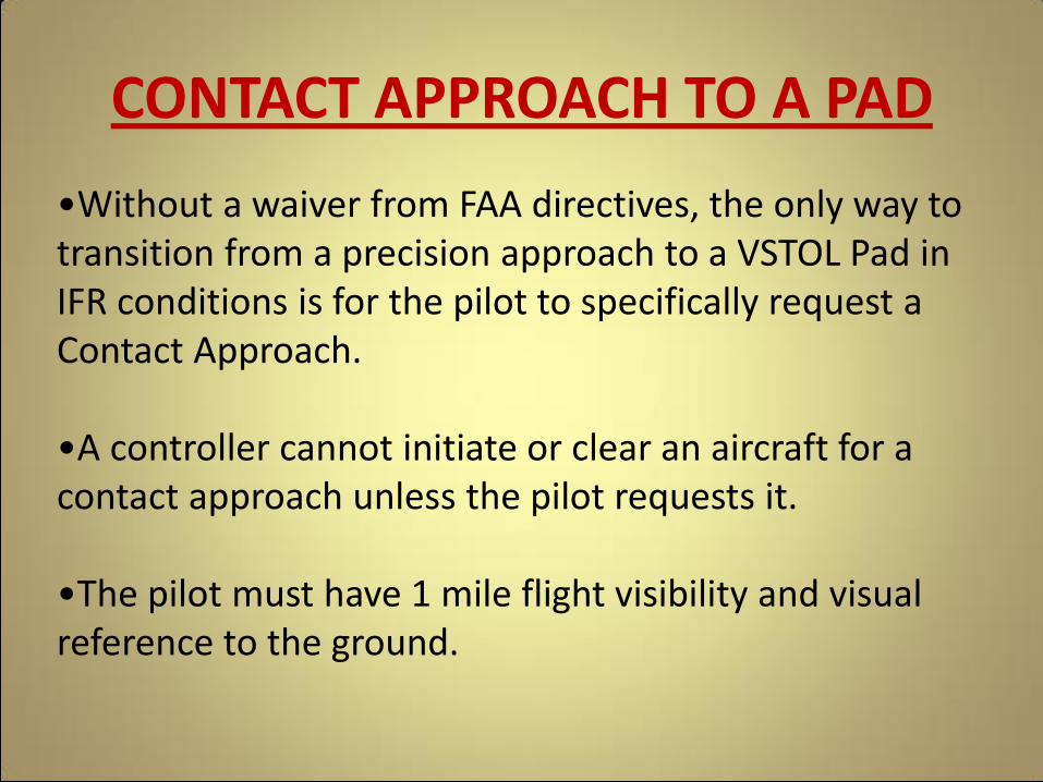
•Without a waiver from FAA directives, the only way to transition from a precision approach to a VSTOL Pad in IFR conditions is for the pilot to specifically request a Contact Approach.
•A controller cannot initiate or clear an aircraft for a contact approach unless the pilot requests it.
•The pilot must have 1 mile flight visibility and visual reference to the ground.
CONTACT APPROACH TO A PAD
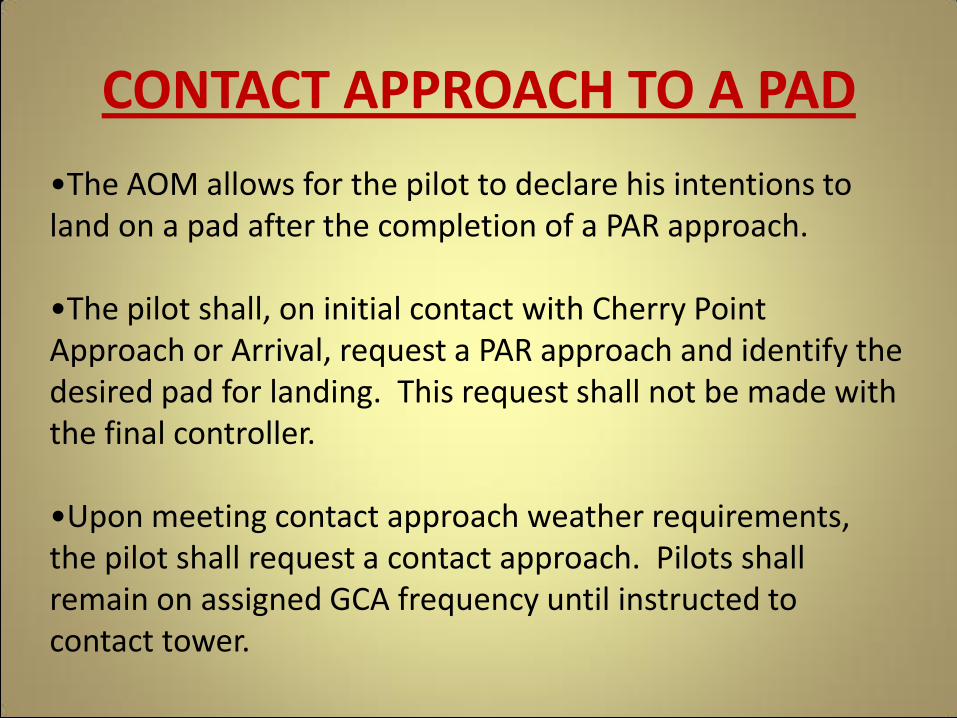
•The AOM allows for the pilot to declare his intentions to land on a pad after the completion of a PAR approach.
•The pilot shall, on initial contact with Cherry Point Approach or Arrival, request a PAR approach and identify the desired pad for landing. This request shall not be made with the final controller.
•Upon meeting contact approach weather requirements, the pilot shall request a contact approach. Pilots shall remain on assigned GCA frequency until instructed to contact tower.
CONTACT APPROACH TO A PAD

Landing at Cherry Point • Cherry Point uses reduced runway separation for Navy and Marine
Corps aircraft (VFR). Separation between full stop aircraft for similar performance or the preceding aircraft is higher performance - 4000’ day/ 6000’ night.
• A low approach may be restricted to 529’ over an aircraft on roll out. Touch-and-go operations require use of the full runway with no other aircraft on it.
• A flight is cleared to land as one aircraft with the lead assuming responsibility for flight separation on final.
• If you are making a full stop, keep your speed up during the roll out. With the reduced runway separation, any aircraft that stops on the runway normally causes someone else to wave-off.
Landing at Cherry Point
A
B
C
D
E
E
F
G
H
I
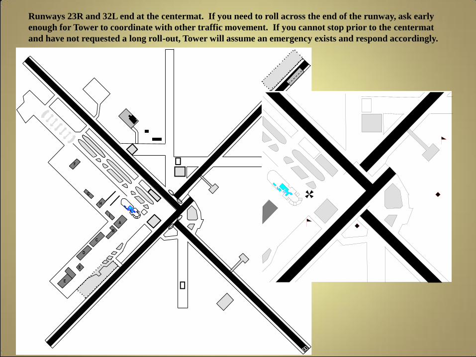
Runways 23R and 32L end at the centermat. If you need to roll across the end of the runway, ask early
enough for Tower to coordinate with other traffic movement. If you cannot stop prior to the centermat
and have not requested a long roll-out, Tower will assume an emergency exists and respond accordingly.

Mars 900 series will be given priority to the maximum extent possible. Airevac and Medevac will normally be given priority over other aircraft.
Note: The AV8s inform Tower of their intentions when “abeam”. It would be beneficial if the intentions were made earlier in the pattern, enabling Tower to plan the pattern accurately. Note: CFR requests that AV8s with gear problems inform the Tower of whether or not the gear has been “blown” down.
Landing at Cherry Point

R/W runway transition SOP
• Overall goal; keep helicopters on the north and west side of the field and away from the center mat area.
• Preferred landing area, runway 14L at the
Juliet taxiway intersection. • If unable to use 14L landing area, land on an
off-duty runway, Foxtrot, Kilo, or the CALA and then transition to Juliet/14L area to your line. Or just land on Mike, Juliet, or November Taxiways.
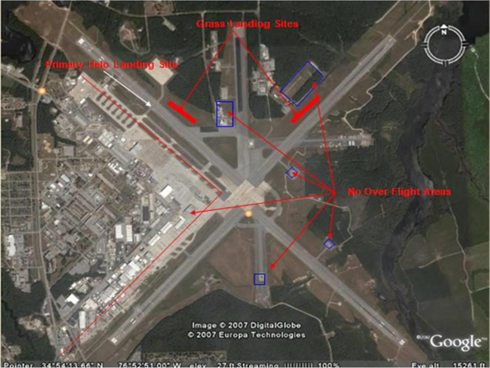
Landing Sites and No Over Flight Areas

UAS Operations
• All UAS operations are included on the daily flight schedule.
• During launch and recovery, Twy “F” and the North Pad will not be available to other aircraft.
• UAS operations will be conducted inside the CDSA and the Areas designated for transit to R5306 A & C.
• 72 hrs prior a NOTAM will be issued to include pertinent details to the UAS transit.
• 1 hr prior to launch a statement will be included on the ATIS.
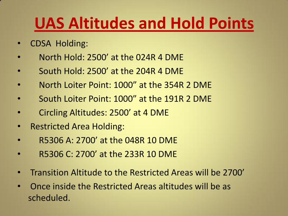
UAS Altitudes and Hold Points • CDSA Holding:
• North Hold: 2500’ at the 024R 4 DME
• South Hold: 2500’ at the 204R 4 DME
• North Loiter Point: 1000” at the 354R 2 DME
• South Loiter Point: 1000” at the 191R 2 DME
• Circling Altitudes: 2500’ at 4 DME
• Restricted Area Holding:
• R5306 A: 2700’ at the 048R 10 DME
• R5306 C: 2700’ at the 233R 10 DME
• Transition Altitude to the Restricted Areas will be 2700’
• Once inside the Restricted Areas altitudes will be as scheduled.
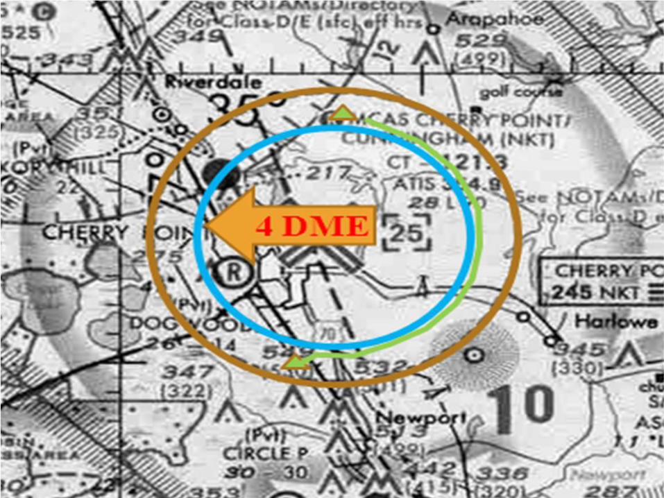
Cherry Point Airspace
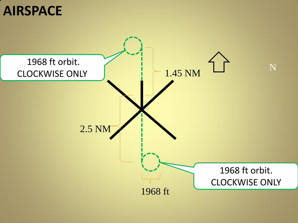
1968 ft orbit. CLOCKWISE ONLY
N 1.45 NM
2.5 NM
1968 ft
1968 ft orbit. CLOCKWISE ONLY
AIRSPACE

NKT TACAN RADIAL/DME
NAME/POINT MGRS
NKT TACAN
RADIAL/ DME
A R-5306A HOLD POINT & LOST LINK
18S UD 40470 78568 048R/10DME
B R-5306A DITCH POINT
18S UD 66000 74999 083R/21DME
C CDSA NORTH HOLD POINT
18S UD 30736 71979 024R/4DME
D
CDSA NORTH RETURN HOME (LOST
LINK)
18S UD 28368 72023 007/4DME
E
CDSA NORTH TALS LOITER POINT
CLOCKWISE ONLY
18S UD 27603 67688 354R/2DME
F
CDSA SOUTH TALS LOITER POINT
CLOCKWISE ONLY
18S UD 28625 60324 191R/2DME
G
CDSA SOUTH HOLD POINT & LOST
LINK
18S UD 26594 55579 204R/4DME
H R-5306C HOLD POINT & LOST LINK
18S UD 15622 50127 233R/10DME
I R-5306C/D DITCH POINT
18S UD 14017 40964 221R/14DME
Cherry Point TRACON
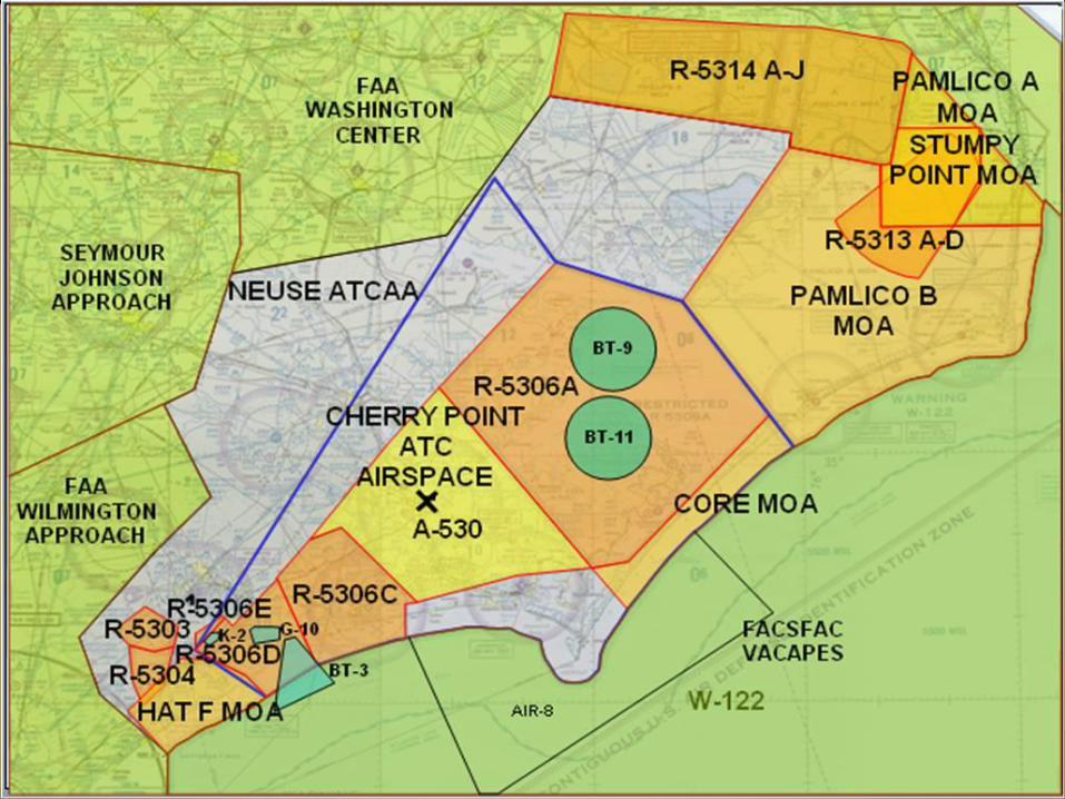
Local Airspace
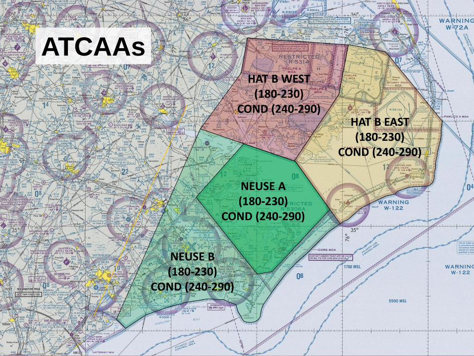
ATCAAs

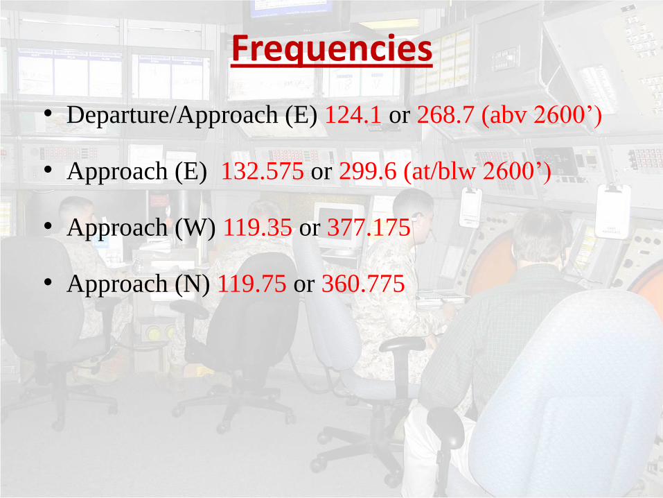
• Departure/Approach (E) 124.1 or 268.7 (abv 2600’)
• Approach (E) 132.575 or 299.6 (at/blw 2600’)
• Approach (W) 119.35 or 377.175
• Approach (N) 119.75 or 360.775
Frequencies

Practice Approaches
VFR Flight Following
Tower Enroute Clearances
Radar Services Available
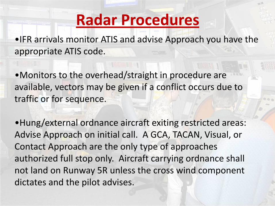
•IFR arrivals monitor ATIS and advise Approach you have the appropriate ATIS code. •Monitors to the overhead/straight in procedure are available, vectors may be given if a conflict occurs due to traffic or for sequence. •Hung/external ordnance aircraft exiting restricted areas: Advise Approach on initial call. A GCA, TACAN, Visual, or Contact Approach are the only type of approaches authorized full stop only. Aircraft carrying ordnance shall not land on Runway 5R unless the cross wind component dictates and the pilot advises.
Radar Procedures

•All GCA patterns are right patterns except Runway 32.
•Airspeed in the arrival pattern - 250 knots maximum. Minimum vectoring altitude is 1600’.
•For Visual Approach - Must have 2100’ ceiling and 3 miles visibility for vectors to a Visual Approach.
•When the duty runway is other than runway 32. TACAN approaches can expect a wave-off if traffic becomes a factor to the duty runway.
Operations
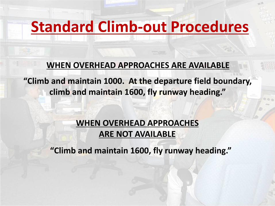
“Climb and maintain 1000. At the departure field boundary, climb and maintain 1600, fly runway heading.”
WHEN OVERHEAD APPROACHES ARE AVAILABLE
“Climb and maintain 1600, fly runway heading.”
WHEN OVERHEAD APPROACHES ARE NOT AVAILABLE
Standard Climb-out Procedures

3 MILES OR LESS ON FINAL WHEN OVERHEAD APPROACHES ARE AVAILABLE
“Climb and maintain 1600, fly runway heading.” or
“Execute Missed Approach”
WHEN OVERHEAD APPROACHES ARE NOT AVAILABLE
“Climb and maintain 1000. At the departure field boundary, climb and maintain 1600, fly runway heading.”
Standard Wave-off Procedures

Rwy 32 - “Climb and maintain 1600, turn left heading 230.”
MORE THAN 3 MILES ON FINAL
Rwy 5 - “Climb and maintain 1600, turn right heading 140.”
Rwy 14 - “Climb and maintain 1600, turn right heading 230.”
Rwy 23 - “Climb and maintain 1600, turn right heading 320.”
Standard Wave-off Procedures

• Airfield Layout
• Taxi / Ground Procedures
• Departure Procedures
• Traffic Patterns
• VFR Entry / Exit Routes
• SVFR Requirements
• Noise Abatement
• Planned Ejection
• Ordnance Jettison
• NORDO Procedures
• Fueling / Fuel Dumping
• Hot Brakes
• Arrival Procedures
• Radar Services
• UAS Operations
Summary
QUESTIONS?