mck and mck-5 · note: the raychem mck-5 motor connection kit is designed for use with shielded or...
TRANSCRIPT

122
Heat-shrinkable motor connections
Type VThe Type V kit is designed to splice thestub or butt configuration that is com-monly used where there is insufficientroom to make in-line connections.
Type LThe Type L kit is used, where space per-mits, to splice in-line connections.
MCK is qualified to ANSI-C119.1-1986and rated to ICEA electrical withstandtest for 1000 V.
MCK-5 is rated to the general electricalrequirements of the IEEE-48 withstandtests.
For use as an in-line or stub splicebetween 1/C poly feeder cable andmotor leads.
Tyco Electronics’ motor connection kitprovides excellent insulation sealing—and resistance to abrasion—in motorconnections.
MCK and MCK-5MCK flame-retardant motor connection kits for 1/C low-voltagepoly cable (1000 V) and MCK-5 motor connection kits for 1/C polycable (5/8.7 kV)
Selection information (dimensions in inches/millimeters)
Connection Catalog Motor feeder size Bolt length length (max.) Lengthnumber (AWG/kcmil) (max.) H (nominal)MCK (1000 V)Type V (stub) CapMCK-1V #14–#10 5/8 2.0 (51) 2.5 (64)MCK-2V #12–#4 3/4 2.5 (64) 3.4 (86)MCK-3V #2–4/0 1 3.5 (89) 4.5 (114)MCK-4V 250–500 1 1/2 5.5 (140) 6.5 (165)Type L (in-line) Sleeve MCK-1L #8–4/0 1 1/4 5.0 (127) 9.0 (229)MCK-2L 250–1000 1 1/2 8.0 (203) 12.0 (305)*MCK (5/8.7 kV)Type V (stub) CapMCK-5-1V #8–#2 1 5.0 (127) 7.5 (191)MCK-5-2V #1–250 1 1/2 6.0 (152) 8.5 (216)MCK-5-3V 300–750 1 1/2 7.0 (178) 9.5 (241)*Type L (in-line) Sleeve MCK-5-1L #8–250 1 6.0 (152) 12.0 (305)MCK-5-2L 300–1000 1 1/2 7.0 (178) 14.0 (356)
Ordering information1. Select appropriate catalog number based on the motor feeder cable. Motor pigtail
leads of the same size or smaller are suitable. MCK selections are based on the typical dimensions of low-voltage insulated cable. MCK-5 selections are based onthe typical dimensions of 100%-insulated cables manufactured in accordance with the data contained in AEIC CS5-1987 and AEIC CS6-1987, as well as the dimensions of commonly used connectors. Nominal insulation thickness (100%): 90 mils. For cables manufactured to other specifications, confirm selection with cable and connector dimensions.
2. Shielded cable must be terminated before installing MCK-5 (use Tyco Electronics HVT-80-G/SG terminations from page 101).
3. MCK and MCK-5 kits are designed for single-hole connectors and include caps and sealant strips for three connections. Kits do not contain connectors.
4. Standard package: MCK: 5 kits/box.MCK-5: 1 kit/box.
5. Related test reports: MCK: EDR-5110 MCK-5: EDR-5010
H
H
Type V Stub configuration
Type L In-line configuration
*
Main IndexMotor Connections Index
Related installation instructionsMCK-xV MCK-5-xL MCK-5-xVMCK-L
EDR-5110EDR-5010

MCK-5-xL5-8kV Class
Motor (In-line) Connection Kits for1/C Medium-Voltage Power Cable
General Instructions
• Cable preparation tools• Raychem P42 cable preparation kit orcable manufacturer approved solvent
• Clean, lint-free cloths• Lug(s) and installation tools• Raychem recommended torch
Recommended Raychem Torches
Install heat-shrinkable cable access-ories with a "clean burning" torch, i.e., a propane torch that does not depositconductive contaminants on the product.
Clean burning torches include theRaychem FH-2609, FH-2629 (usesrefillable propane cylinders) and FH-2616A1 (uses disposable cylinder).
Adjusting the Torch
Adjust regulator and torch as requiredto provide an overall 12- inch bushyflame.
The FH-2629 will be all blue, the othertorches will have a 3- to 4-inch yellowtip. Use the yellow tip for shrinking.
Regulator Pressure
FH-2616A1 Full pressureFH-2609 5 psigFH-2629 15 psig
General Shrinking Instructions
• Apply outer 3- to 4-inch tip of theflame to heat-shrinkable material with arapid brushing motion.• Keep flame moving to avoidscorching.• Unless otherwise instructed, startshrinking tube at center, working flamearound all sides of the tube to applyuniform heat.
To determine if a tube has completelyrecovered, look for the following,especially on the back and underside ofthe tube:
1. Uniform wall thickness.2. Conformance to substrate.3. No flat spots or chill marks.4. Visible sealant flow if the tube is
coated.
Safety Instructions
Warning: When installing electricalpower system accessories, failure tofollow applicable personal safetyrequirements and written installationinstructions could result in fire orexplosion and serious or fatal injuries.
To avoid risk of accidental fire orexplosion when using gas torches,always check all connections for leaksbefore igniting the torch and follow thetorch manufacturer's safety instructions.
To minimize any effect of fumesproduced during installation, alwaysprovide good ventilation of confinedwork spaces.
Suggested Installation Equipment (not supplied with kit)
Installation Instructions
PII-54730, Rev ACDCR C28106
PCN 183441-000Effective Date: May 22, 1996
1

3. Install lug cover.
Center the lug cover sleeve over thebolted connection and shrink in place.
Lug Cover
Note: MCK insulating caps are designed to accommodate the largest lugs normally used. However, manyinstallations require shorter caps due to space limitations. MCK can be trimmed to any desired length as long as thefollowing rules are observed.
• The cuts must be clean with no jagged edges.• The cap length must be sufficient to completely cover the mastic strips – approximately 1-1/2" (40mm) beyond
the end of the longest lug barrel.• If the cap is trimmed, an equal length should be trimmed from the lug cover sleeve.
Motor Lead
Terminated Feeder Cable
Outer Insulating Sleeve
1/4" (5mm) Maximum
Lug Cover
2. Position tubes; install lugs.
After completing phase rotationcheck, align motor lead with appro-priate feeder cable.
Remove all fiber braid (if any) fromthe cables and clean for 6" (150mm)beyond each lug. Place the tubesover the cables as shown.
Install lugs on feeder cables andmotor leads. Bolt connections tight.Insert bolt through tang of largest lugfirst. Bolt must not extend throughnut more than 1/4" (5mm).
1877
Installation Instructions
PII-54730, Rev ACDCR C28106
PCN 183441-000Effective Date: May 22, 1996
2
1. Product selection.
Check kit selection with cabledimensions in Table 1.
Table 1Motor Feeder Bolt Length Connection Length
Kit Conductor Size Max (D) Max (H)
MCK-5-1L #8-250 kcmil 1" (25mm) 6.0" (150mm)MCK-5-2L 300-1000 kcmil 1-1/2" (40mm) 7.0" (175mm)
H
D
Note: The Raychem MCK-5 Motor Connection Kit is designed for use withshielded or unshielded feeder cables. When shielded cables are used, aRaychem HVT termination kit is recommended to terminate the feedercable prior to installation of the MCK-5.

PII-54730, Rev ACDCR C28106, PCN 183441-000Effective Date: May 22, 1996
1996 Raychem CorporationPrinted USA 5/22/96
3
6. Position tube; shrink in place.
Center the outer sleeve over theconnection area, covering themastic wraps. Begin shrinking atthe center, working the torch with asmooth, brushing motion around allsides of the sleeve.
Continue to each end end as thesleeve shrinks and conforms to thecable contours. Post heat sleeve forapproximately 30 seconds aftersleeve has fully shrunk.
Allow to cool enough to touch beforereplacing in motor terminal box.
Installation is complete.
Outer Insulating Sleeve
1881
5. Apply mastic.
Remove release papers from masticstrip. Make one complete wrap ofmastic around the feeder cable, justinside the mark made in Step 4.
Wrap mastic around the motor lead(just inside mark made in Step 4).Make as many wraps as necessaryto build the motor lead up to thediameter of the lug cover sleeve.Discard excess mastic.
Build mastic to level of lug cover
1 Wrap Mastic
Centering Marks
1880
Post heat 30 seconds
1882
4. Mark cables.
Center the outer insulating sleeveover the connection area and markits end positions on the cables.
Centering Marks Center tube over connection and mark ends
1879
Installation Instructions

Product Installation Instructions
MCK-5-xV5-8kV Class
Motor (Stub) Connection Kits for1/C Medium-Voltage Power Cable
General Instructions
• Raychem P63 cable preparation kit orcable manufacturer approved solvent
• Cable preparation tools• Clean, lint-free cloths
• Lug(s) and installation tools
Suggested Installation Equipment (not supplied with kit)
1. Product selection.Check kit selection with cabledimensions in Table 1.
Installation Instructions
Table 1Motor Feeder Bolt Length Connection Length
Kit Conductor Size Max (D) Max (H)MCK-5-1V #8-#2 AWG 1" (25mm) 5.0" (156mm)MCK-5-2V #1-250 kcmil 1-1/2" (40mm) 6.0" (150mm)MCK-5-3V 300-750 kcmil 1-1/2" (40mm) 7.0" (175mm)H
D
Note: The Raychem MCK-5 Motor Connection Kit is designed for use withshielded or unshielded feeder cables. When shielded cables are used, a RaychemHVT termination kit is recommended to terminate the feeder cable prior toinstallation of the MCK-5.
Recommended Raychem TorchesInstall heat-shrinkable cable accessorieswith a "clean burning" torch, i.e., apropane torch that does not depositconductive contaminants on the product.
Clean burning torches include theRaychem FH-2609, FH-2629 (usesrefillable propane cylinders) and FH-2616A1 (uses disposable cylinder).
Cleaning the CableUse an approved solvent, such as theone supplied in the P63 Cable Prep Kit,to clean the cable. Be sure to follow themanufacturer's instructions. Failure tofollow these instructions could lead toproduct failure.
Some newer solvents do not evaporatequickly and need to be removed with aclean, lint-free cloth. Failure to do socould change the volume resistivity ofthe substrate or leave a residue on thesurface.
Please follow the manufacturer'sinstructions carefully.
Note: When installing multiple tubes,make sure that the surface of the lasttube is still warm before positioning andshrinking the next tube. If installed tubehas cooled, re-heat the entire surface.
General Shrinking Instructions• Apply outer 3- to 4-inch tip of theflame to heat-shrinkable material with arapid brushing motion.• Keep flame moving to avoidscorching.• Unless otherwise instructed, startshrinking tube at center, working flamearound all sides of the tube to applyuniform heat.
To determine if a tube has completelyrecovered, look for the following,especially on the back and underside ofthe tube:
1. Uniform wall thickness.2. Conformance to substrate.3. No flat spots or chill marks.4. Visible sealant flow if the tube is
coated.
Safety InstructionsWarning: When installing electricalpower system accessories, failure tofollow applicable personal safetyrequirements and written installationinstructions could result in fire orexplosion and serious or fatal injuries.
To avoid risk of accidental fire orexplosion when using gas torches,always check all connections for leaksbefore igniting the torch and follow thetorch manufacturer's safety instructions.To minimize any effect of fumesproduced during installation, alwaysprovide good ventilation of confinedwork spaces.
As Raychem has no control over fieldconditions which influence productinstallation, it is understood that theuser must take this into account andapply his own experience andexpertise when installing product.
Adjusting the TorchAdjust regulator and torch as required toprovide an overall 12- inch bushy flame.The FH-2629 will be all blue, the other
torches will have a 3- to 4-inch yellowtip. Use the yellow tip for shrinking.
Regulator PressureFH-2616A1 Full pressureFH-2609 5 psigFH-2629 15 psig

Feeder Cable
Motor Lead
3" (75mm)
Parallel Length
���������������
Termination
1/4" (5mm) Maximum
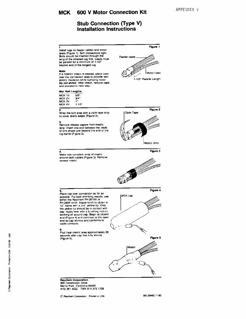
2. Install lugs.After completing phase rotation check, alignmotor lead with appro-priate feeder cable.Leads must be parallel for a minimum of 3"(75mm) beyond the end of the longest lug.Remove all fiber braid (if any) from the motorlead. Clean both cables with approved solvent.Install lugs on feeder cables and motor leads.Bolt connections tight. Insert bolt through tangof smallest lug first. Bolt must not extendthrough nut more than 1/4" (5mm). 1871
Product Installation Instructions
PII-54731, Rev ADDCR C27269, PCN 056597-000Effective Date: June 7 1995
1995 Raychem CorporationPrinted USA 6/7/95
2
Note: MCK insulating caps are designed to accommodate the largest lugs normally used. However, manyinstallations require shorter caps due to space limitations. MCK can be trimmed to any desired length as long as thefollowing rules are observed.
• The cuts must be clean with no jagged edges.• The cap length must be sufficient to completely cover the mastic strips – approximately 1-1/2" (40mm) beyond
the end of the longest lug barrel.• If the cap is trimmed, an equal length should be trimmed from the lug cover sleeve.
3. Install lug cover.Place the lug cover sleeve over the boltedconnection and shrink in place.
Lug Cover 1872
4. Apply mastic.Remove release papers from mastic strip. Insertone end between the leads of one phase justbeyond the end of the lug cover sleeve.
Make one complete wrap of mastic around bothcables. Discard excess mastic.
Mastic
1873
5. Preheat mastic.Heat the mastic with a brushing motion forapproximately 15 seconds or until surfacefoaming occurs.
Preheat Mastic����������������������������������������������������������������������������������������������������
@@@@@@@@@@@@@@@@@@@@@@@@@@@@@@@@@@@@@@@@@@@@@@@@@@@@@@@@@@@@@@@@@@@@@@@@@@@@@@@@@@@@@@@@@@@@@@@@@@@@
����������������������������������������������������������������������������������������������������
ÀÀÀÀÀÀÀÀÀÀÀÀÀÀÀÀÀÀÀÀÀÀÀÀÀÀÀÀÀÀÀÀÀÀÀÀÀÀÀÀÀÀÀÀÀÀÀÀÀÀÀÀÀÀÀÀÀÀÀÀÀÀÀÀÀÀÀÀÀÀÀÀÀÀÀÀÀÀÀÀÀÀÀÀÀÀÀÀÀÀÀÀÀÀÀÀÀÀÀÀ
����������������������������������������������������������������������������������������������������
@@@@@@@@@@@@@@@@@@@@@@@@@@@@@@@@@@@@@@@@@@@@@@@@@@@@@@@@@@@@@@@@@@@@@@@@@@@@@@@@@@@@@@@@@@@@@@@@@@@@
����������������������������������������������������������������������������������������������������
ÀÀÀÀÀÀÀÀÀÀÀÀÀÀÀÀÀÀÀÀÀÀÀÀÀÀÀÀÀÀÀÀÀÀÀÀÀÀÀÀÀÀÀÀÀÀÀÀÀÀÀÀÀÀÀÀÀÀÀÀÀÀÀÀÀÀÀÀÀÀÀÀÀÀÀÀÀÀÀÀÀÀÀÀÀÀÀÀÀÀÀÀÀÀÀÀÀÀÀÀ
1874
MCK Cap
����������������������������������������������������������������������������������������������������
@@@@@@@@@@@@@@@@@@@@@@@@@@@@@@@@@@@@@@@@@@@@@@@@@@@@@@@@@@@@@@@@@@@@@@@@@@@@@@@@@@@@@@@@@@@@@@@@@@@@
����������������������������������������������������������������������������������������������������
ÀÀÀÀÀÀÀÀÀÀÀÀÀÀÀÀÀÀÀÀÀÀÀÀÀÀÀÀÀÀÀÀÀÀÀÀÀÀÀÀÀÀÀÀÀÀÀÀÀÀÀÀÀÀÀÀÀÀÀÀÀÀÀÀÀÀÀÀÀÀÀÀÀÀÀÀÀÀÀÀÀÀÀÀÀÀÀÀÀÀÀÀÀÀÀÀÀÀÀÀ
����������������������������������������������������������������������������������������������������
@@@@@@@@@@@@@@@@@@@@@@@@@@@@@@@@@@@@@@@@@@@@@@@@@@@@@@@@@@@@@@@@@@@@@@@@@@@@@@@@@@@@@@@@@@@@@@@@@@@@
����������������������������������������������������������������������������������������������������
ÀÀÀÀÀÀÀÀÀÀÀÀÀÀÀÀÀÀÀÀÀÀÀÀÀÀÀÀÀÀÀÀÀÀÀÀÀÀÀÀÀÀÀÀÀÀÀÀÀÀÀÀÀÀÀÀÀÀÀÀÀÀÀÀÀÀÀÀÀÀÀÀÀÀÀÀÀÀÀÀÀÀÀÀÀÀÀÀÀÀÀÀÀÀÀÀÀÀÀÀ
Mastic Flow����������������������������������������������������������������������������������������������������
@@@@@@@@@@@@@@@@@@@@@@@@@@@@@@@@@@@@@@@@@@@@@@@@@@@@@@@@@@@@@@@@@@@@@@@@@@@@@@@@@@@@@@@@@@@@@@@@@@@@
����������������������������������������������������������������������������������������������������
ÀÀÀÀÀÀÀÀÀÀÀÀÀÀÀÀÀÀÀÀÀÀÀÀÀÀÀÀÀÀÀÀÀÀÀÀÀÀÀÀÀÀÀÀÀÀÀÀÀÀÀÀÀÀÀÀÀÀÀÀÀÀÀÀÀÀÀÀÀÀÀÀÀÀÀÀÀÀÀÀÀÀÀÀÀÀÀÀÀÀÀÀÀÀÀÀÀÀÀÀ
����������������������������������������������������������������������������������������������������
@@@@@@@@@@@@@@@@@@@@@@@@@@@@@@@@@@@@@@@@@@@@@@@@@@@@@@@@@@@@@@@@@@@@@@@@@@@@@@@@@@@@@@@@@@@@@@@@@@@@
����������������������������������������������������������������������������������������������������
ÀÀÀÀÀÀÀÀÀÀÀÀÀÀÀÀÀÀÀÀÀÀÀÀÀÀÀÀÀÀÀÀÀÀÀÀÀÀÀÀÀÀÀÀÀÀÀÀÀÀÀÀÀÀÀÀÀÀÀÀÀÀÀÀÀÀÀÀÀÀÀÀÀÀÀÀÀÀÀÀÀÀÀÀÀÀÀÀÀÀÀÀÀÀÀÀÀÀÀÀ
1875
1876
6. Position cap; shrink in place.Place the cap over the connection as far aspossible. Begin shrinking at the closed end,working the torch with a smooth, brushingmotion around all sides of the cap.Continue to the open end as the cap shrinksand conforms to the cable contours. Post heatmastic area approximately 30 seconds aftercap has fully shrunk.With gloved hand or cloth, compress the masticarea to knead the sealant between the leads.Allow to cool enough to touch before replacingin motor terminal box. Repeat Steps 2-6 forremaining phases.Installation is complete.

Instrucciones Generales
• Herramientas de preparación decables• Trapos limpios libres de peluzas• Soplete recomendado por Raychem
• Equipo de preparación de cablesRaychem p63 o solvente aprobado porel fabricante
• Cinta de electricista
• Tela o papel abrasivo, no-conductivo,de fineza 120 o más fina• Conector(es) y herramientas deinstalación
Equipo Sugerido de Instalación (no se suministra con el equipo)
Nota: Cuando se instalen tubosmúltiples, asegúrese de que lasuperficie del último esté todavíacaliente, antes de acoplar y encoger elsiguiente tubo. Si instala el tubo enfrio, recaliente la superfie entera.
Instrucciones Generales deTermocontracción
• Aplique el extremo exterior de 3 a 4pulgadas de la flama, al materialtermocontractil al calor con un suavemovimiento de cepillado.• Mantenga la flama moviéndose paraobtenér una termocontracción uniformey evitar el chamusqueo.
A menos que se le instruya de hacerlodistinto, comience a termocontraer eltubo desde el centro, trabajando laflama alrededor de todas las partes deltubo para aplicar un calor uniforme.Para determinar si el tubo se hainstalado corarectamente obsérveloespecialmente en la parte de atrás:
l.-Grosor uniforme de las paredes.2.-Confomación de los substratos.3.-Sin puntos planos o marcas frías.4.-Flujo sellador visible si el tuboesta cubierto.
Ajustando el soplete
Ajuste el regulador y el soplete como serequiere, para asi proporcionar unaflama espesa de un total de 12pulgadas.
En el FH-2629 la flama será toda azul,los otros sopletes tendrán un extremoamarillo de 3 a 4 pulgadas. Use elextremo amarillo para latermocontracción.
Presión del regulador
FH-2616A1 Presión completaFH-2609 5 psigFH-2629 15 psig
Instale los accessorios termocontráctilescon un soplete de flama limpia, ejemplo:un soplete de propano que no deposite
Sopletes Recomendados por Raychem
Instrucciones de seguridad
Advertencia: Cuando se instalen losaccesorios del sistema de energíaeléctrica, el no seguir los requerimientospersonales de seguridad y lasinstrucciones escritas referente a lainstalación, podría dar como resultado un incendio o una explosión y causarserios o fatales perjuicios.Para evitar riesgo de fuego accidental o
de explosión, cuando se utilicensopletes de gas, siempre revise todaslas conexiones por fugas, antes de encender el soplete y siga lasinstrucciones de seguridad del soplete.Para minimizar cualquier efecto dehumo producido durante la instalación,provéase siempre de una buenaventilación en el lugar de trabajo.
Como Raychem no controla todas lascondiciones que pueden influir en lainstalación del producto en campo,queda entendido que el usuario debetomar esto en cuenta y aplicar supropia experiencia y práctica cuandoinstale el producto.
Limpieza del Cable
Use un solvente adecuado como elprovisto en el kit P63. Asegúrese deseguir las instrucciones del producto.Un descuido puede provocar que elproducto falle.
Algunos solventes nuevos no seevaporan rapidamente y necesitan serremovidos con un paño limpio y libre depeluzas. De no ser así, puedenprovocarse cambios en la
resistividad volumétrica del sustrato odejar residuos en la superficie.
Siga cuidadosamente las instruccionesdel fabricante.
Instructivo de Instalación
MCK-5-xV5-8kV Kit de Conexión deMotores Conexiones de Punta (Tipo V)
PII-54731, Rev ADDCR C27269
PCN 056597-000Effective Date: Junio 7 1995
contaminantes conductivos en el producto. Los sopletes de flama limpia incluyen al Raychem FH-2609, Fh-2629(usa cilindros de propano recargables) yFH-2616Al (usa cilindros desechables).

5. Cubra la conexión con la manga ycontraigala en el lugar* (Fig. 2).
*NOTA: Las mangas de aislamiento MCK-5,están diseñadas para cubrir al conector másgrande normalmente utilizado. Sin embargo,algunas instalaciones requieren mangas máscortas debido a las limitaciones de espacio. ElMCK-5 puede acondicionarse a la Iongituddeseada siempre y cuando se observen lassiguientes-reglas:• El corte debe ser limpio sin bordes dentados.• El capuchón debe ser lo suficientementelargo para cubrir completamente la tira deadhesivo inclusive hasta 1 1/2 pulgadas másallá del borde del conector.• Si se acondiciona el capuchón a una longitudrequerida también debe acondicionarse lamanga que cubre la conexión.
6. Continue calentando por espacio de unos15 segundos adicionales, justo debajo de lamanga que cubre la conexión (Fig. 2).
���������������
Lug Cover
1872
Manga Cubre Conector
Figura 2
Instructivo de Instalación
2. Después de completar el chequeode la fase de rotación, alinie el cabledel motor con el cable alimentadorapropiado. Asegurese que el cablealimentador y el cable del motor esténparalelos dentro de una distanciamínima de 3 pulg. a partir del extremodel conector del cable del motor,como se muestra en la Fig. 1 .
3. Remueva todo el trenzado (si lohay) del cable del motor. Limpieambos cables con un solventeapropiado.
4. Realice la conexión de los cables.En caso de utilizár tornillo en laconexión, asegurese que el alto de larosca a traves de la tuerca no sobre-salga mas de 1/4 de pulg. (Fig. 1).
Feeder Cable
Motor Lead
3" (75mm)
Parallel Length
���������������
Termination
1/4" (5mm) Maximum
1871
Figura 1 Cable Alimentador
Cable del Motor
1/4”(5mm)max.
1. Selección del Producto.
Verique la sellección del kit con lasdimensiones del cable en la Tabla 1.
Tabla 1 Longitud deCalibre Longitud tornillo la Conexión
Kit Alimentador Max (D) Max (H)MCK-5-1V #8-#2 AWG 1" (25mm) 5.0" (156mm)MCK-5-2V #1-250 kcmil 1-1/2" (40mm) 6.0" (150mm)MCK-5-3V 300-750 kcmil 1-1/2" (40mm) 7.0" (175mm)
H
D
Nota: El Kit Raychem MCK-5 para Conexión de Motor, está diseñadopara usarse con cables alimentadores con o sin pantalla. Cuando se useen cables con pantalla, se recomienda utilizar una terminal Raychem HVTen el cable alimentador antes de instalar el MCK-5.
PII-54731, Rev ADDCR C27269
PCN 056597-000Effective Date: Junio 7 1995
2

7. Remueva la tira de papel protector deladhesivo. lntroduzca una punta de la tira deadhesivo entre los cables justo al final de lamanga que cubre la conexión.
8. Con la tira de adhesivo dele una vueltacompleta alrededor de ambos cables.
9. Caliente el adhesivo con movimientoscontinuos por espacio de 15 segundos o hastaque la superficie se torne espumosa. (Fig. 4).
Mastic1873
������
Preheat Mastic����������������������������������������������������������������������������������������������������
@@@@@@@@@@@@@@@@@@@@@@@@@@@@@@@@@@@@@@@@@@@@@@@@@@@@@@@@@@@@@@@@@@@@@@@@@@@@@@@@@@@@@@@@@@@@@@@@@@@@
����������������������������������������������������������������������������������������������������
ÀÀÀÀÀÀÀÀÀÀÀÀÀÀÀÀÀÀÀÀÀÀÀÀÀÀÀÀÀÀÀÀÀÀÀÀÀÀÀÀÀÀÀÀÀÀÀÀÀÀÀÀÀÀÀÀÀÀÀÀÀÀÀÀÀÀÀÀÀÀÀÀÀÀÀÀÀÀÀÀÀÀÀÀÀÀÀÀÀÀÀÀÀÀÀÀÀÀÀÀ
����������������������������������������������������������������������������������������������������
@@@@@@@@@@@@@@@@@@@@@@@@@@@@@@@@@@@@@@@@@@@@@@@@@@@@@@@@@@@@@@@@@@@@@@@@@@@@@@@@@@@@@@@@@@@@@@@@@@@@
����������������������������������������������������������������������������������������������������
ÀÀÀÀÀÀÀÀÀÀÀÀÀÀÀÀÀÀÀÀÀÀÀÀÀÀÀÀÀÀÀÀÀÀÀÀÀÀÀÀÀÀÀÀÀÀÀÀÀÀÀÀÀÀÀÀÀÀÀÀÀÀÀÀÀÀÀÀÀÀÀÀÀÀÀÀÀÀÀÀÀÀÀÀÀÀÀÀÀÀÀÀÀÀÀÀÀÀÀÀ
����������������������������������������������������������������������������������������������������
@@@@@@@@@@@@@@@@@@@@@@@@@@@@@@@@@@@@@@@@@@@@@@@@@@@@@@@@@@@@@@@@@@@@@@@@@@@@@@@@@@@@@@@@@@@@@@@@@@@@
����������������������������������������������������������������������������������������������������
ÀÀÀÀÀÀÀÀÀÀÀÀÀÀÀÀÀÀÀÀÀÀÀÀÀÀÀÀÀÀÀÀÀÀÀÀÀÀÀÀÀÀÀÀÀÀÀÀÀÀÀÀÀÀÀÀÀÀÀÀÀÀÀÀÀÀÀÀÀÀÀÀÀÀÀÀÀÀÀÀÀÀÀÀÀÀÀÀÀÀÀÀÀÀÀÀÀÀÀÀ
1874
Figura 3
Figura 4
Manga contraidasobre el Conector
Adhesivo
Tira de Adhesivo
MCK Cap
����������������������������������������������������������������������������������������������������
@@@@@@@@@@@@@@@@@@@@@@@@@@@@@@@@@@@@@@@@@@@@@@@@@@@@@@@@@@@@@@@@@@@@@@@@@@@@@@@@@@@@@@@@@@@@@@@@@@@@
����������������������������������������������������������������������������������������������������
ÀÀÀÀÀÀÀÀÀÀÀÀÀÀÀÀÀÀÀÀÀÀÀÀÀÀÀÀÀÀÀÀÀÀÀÀÀÀÀÀÀÀÀÀÀÀÀÀÀÀÀÀÀÀÀÀÀÀÀÀÀÀÀÀÀÀÀÀÀÀÀÀÀÀÀÀÀÀÀÀÀÀÀÀÀÀÀÀÀÀÀÀÀÀÀÀÀÀÀÀ
����������������������������������������������������������������������������������������������������
@@@@@@@@@@@@@@@@@@@@@@@@@@@@@@@@@@@@@@@@@@@@@@@@@@@@@@@@@@@@@@@@@@@@@@@@@@@@@@@@@@@@@@@@@@@@@@@@@@@@
����������������������������������������������������������������������������������������������������
ÀÀÀÀÀÀÀÀÀÀÀÀÀÀÀÀÀÀÀÀÀÀÀÀÀÀÀÀÀÀÀÀÀÀÀÀÀÀÀÀÀÀÀÀÀÀÀÀÀÀÀÀÀÀÀÀÀÀÀÀÀÀÀÀÀÀÀÀÀÀÀÀÀÀÀÀÀÀÀÀÀÀÀÀÀÀÀÀÀÀÀÀÀÀÀÀÀÀÀÀ
����������������������������������������������������������������������������������������������������
@@@@@@@@@@@@@@@@@@@@@@@@@@@@@@@@@@@@@@@@@@@@@@@@@@@@@@@@@@@@@@@@@@@@@@@@@@@@@@@@@@@@@@@@@@@@@@@@@@@@
����������������������������������������������������������������������������������������������������
ÀÀÀÀÀÀÀÀÀÀÀÀÀÀÀÀÀÀÀÀÀÀÀÀÀÀÀÀÀÀÀÀÀÀÀÀÀÀÀÀÀÀÀÀÀÀÀÀÀÀÀÀÀÀÀÀÀÀÀÀÀÀÀÀÀÀÀÀÀÀÀÀÀÀÀÀÀÀÀÀÀÀÀÀÀÀÀÀÀÀÀÀÀÀÀÀÀÀÀÀ
1875
10. Introduzca la conexión hasta el extremo delcapuchón. Comience a contraer el capuchóndesde el extremo cerrado hacia el extremoabierto, moviendo continuamente la flama.
*NOTA: Si el capuchón es muy largo refiérasea los pasos para el acondicionamiento en elPunto 5.
11. Una vez contraido completamente elcapuchón, continue calentando por espacio deunos 30 segundos el área sobre la cual colocóel adhesivo.
12. Con la mano protegida por un guante opaño, comprima el área donde aplicó eladhesivo para conformar el sello entre loscables. Una vez completado este paso puededarse por concluida la conexión.
13. Repita los pasos para las otras fases.
14. Todas las conexiones deben estarsuficientemente frías al tacto para introducirlasen la caja terminal del motor.
Mastic Flow����������������������������������������������������������������������������������������������������
@@@@@@@@@@@@@@@@@@@@@@@@@@@@@@@@@@@@@@@@@@@@@@@@@@@@@@@@@@@@@@@@@@@@@@@@@@@@@@@@@@@@@@@@@@@@@@@@@@@@
����������������������������������������������������������������������������������������������������
ÀÀÀÀÀÀÀÀÀÀÀÀÀÀÀÀÀÀÀÀÀÀÀÀÀÀÀÀÀÀÀÀÀÀÀÀÀÀÀÀÀÀÀÀÀÀÀÀÀÀÀÀÀÀÀÀÀÀÀÀÀÀÀÀÀÀÀÀÀÀÀÀÀÀÀÀÀÀÀÀÀÀÀÀÀÀÀÀÀÀÀÀÀÀÀÀÀÀÀÀ
����������������������������������������������������������������������������������������������������
@@@@@@@@@@@@@@@@@@@@@@@@@@@@@@@@@@@@@@@@@@@@@@@@@@@@@@@@@@@@@@@@@@@@@@@@@@@@@@@@@@@@@@@@@@@@@@@@@@@@
����������������������������������������������������������������������������������������������������
ÀÀÀÀÀÀÀÀÀÀÀÀÀÀÀÀÀÀÀÀÀÀÀÀÀÀÀÀÀÀÀÀÀÀÀÀÀÀÀÀÀÀÀÀÀÀÀÀÀÀÀÀÀÀÀÀÀÀÀÀÀÀÀÀÀÀÀÀÀÀÀÀÀÀÀÀÀÀÀÀÀÀÀÀÀÀÀÀÀÀÀÀÀÀÀÀÀÀÀÀ
����������������������������������������������������������������������������������������������������
@@@@@@@@@@@@@@@@@@@@@@@@@@@@@@@@@@@@@@@@@@@@@@@@@@@@@@@@@@@@@@@@@@@@@@@@@@@@@@@@@@@@@@@@@@@@@@@@@@@@
����������������������������������������������������������������������������������������������������
ÀÀÀÀÀÀÀÀÀÀÀÀÀÀÀÀÀÀÀÀÀÀÀÀÀÀÀÀÀÀÀÀÀÀÀÀÀÀÀÀÀÀÀÀÀÀÀÀÀÀÀÀÀÀÀÀÀÀÀÀÀÀÀÀÀÀÀÀÀÀÀÀÀÀÀÀÀÀÀÀÀÀÀÀÀÀÀÀÀÀÀÀÀÀÀÀÀÀÀÀ
1876
Figura 5
Figura 6
Adhesivo Fluye
PII-54731, Rev ADDCR C27269, PCN 056597-000Effective Date: Junio 7 1995
1995 Raychem CorporationPrinted USA 6/7/95
3
Instructivo de Instalación

1. Product selection. Check kit selection with cable dimensions in Table 1.
Product Installation Instructions
MCK-xV
1000V Flame-Retarded Motor (Stub) Connection Kits for 1/C Low-Voltage Power Cable
Installation Instructions
Table 1Motor Feeder Bolt Length Connection Length
Kit Conductor Size Max (D) Max (H)
MCK-1V #14-#10 AWG 5/8" (15mm) 2.0" (50mm)MCK-2V #12-#4 AWG 3/4" (20mm) 2.5" (65mm)MCK-3V #2-4/0 AWG 1" (25mm) 3.5" (89mm)MCK-4V 250-500 kcmil 1-1/2" (35mm) 5.5" (140mm)H
D
General Instructions
• Raychem P63 cable preparation kit orcable manufacturer approved solvent
• Cable preparation tools• Clean, lint-free cloths
• Lug(s) and installation tools
Suggested Installation Equipment (not supplied with kit)
Recommended Raychem TorchesInstall heat-shrinkable cable accessorieswith a "clean burning" torch, i.e., apropane torch that does not depositconductive contaminants on the product.
Clean burning torches include theRaychem FH-2629 (uses refillablepropane cylinders) and FH-2618A1 (uses disposable cylinder).
Cleaning the CableUse an approved solvent, such as theone supplied in the P63 Cable Prep Kit,to clean the cable. Be sure to follow themanufacturer's instructions. Failure tofollow these instructions could lead toproduct failure.
Some newer solvents do not evaporatequickly and need to be removed with aclean, lint-free cloth. Failure to do socould change the volume resistivity ofthe substrate or leave a residue on thesurface.
Please follow the manufacturer'sinstructions carefully.
Note: When installing multiple tubes,make sure that the surface of the lasttube is still warm before positioning andshrinking the next tube. If installed tubehas cooled, re-heat the entire surface.
General Shrinking Instructions• Apply outer 3- to 4-inch tip of theflame to heat-shrinkable material with arapid brushing motion.• Keep flame moving to avoidscorching.• Unless otherwise instructed, startshrinking tube at center, working flamearound all sides of the tube to applyuniform heat.
To determine if a tube has completelyrecovered, look for the following,especially on the back and underside ofthe tube:
1. Uniform wall thickness.2. Conformance to substrate.3. No flat spots or chill marks.4. Visible sealant flow if the tube is
coated.
Safety InstructionsWarning: When installing electricalpower system accessories, failure tofollow applicable personal safetyrequirements and written installationinstructions could result in fire orexplosion and serious or fatal injuries.
To avoid risk of accidental fire orexplosion when using gas torches,always check all connections for leaksbefore igniting the torch and follow thetorch manufacturer's safety instructions.To minimize any effect of fumesproduced during installation, alwaysprovide good ventilation of confinedwork spaces.
As Raychem has no control over fieldconditions which influence productinstallation, it is understood that theuser must take this into account andapply his own experience andexpertise when installing product.
Adjusting the TorchAdjust regulator and torch as required toprovide an overall 12- inch bushy flame.The FH-2629 will be all blue, the other
torches will have a 3- to 4-inch yellowtip. Use the yellow tip for shrinking.
Regulator PressureFH-2618A1 Full pressureFH-2629 15 psig

Installation Instructions
Feeder Cable
Motor Lead
1-1/2" (40mm)Parallel Length
Cloth Tape
1864
4. Appl y mastic to cab le jacket.
Remove release papers from masticstrip. Insert one end between theleads of one phase just beyond theend of the lug barrel.
Make one complete wrap of masticaround both cables. Discard excessmastic.
Mastic
1865
5. Position cap; shrink in place .
Place the cap over the connectionas far as possible. Begin shrinkingat the closed end, working the torchwith a smooth, brushing motionaround all sides of the cap.
Continue to the open end as thecap shrinks and conforms to thecable contours. Post heat masticarea approximately 20 secondsafter cap has fully shrunk.
Installation is complete .
MCK Cap
Post Heat MasticArea 20 seconds
1866
PII-51081, Rev ADPCN 043944-000Effective Date: September 21, 2000
2000 Tyco Electronics CorporationPrinted USA 9/21/00
2
3. Appl y cloth tape to lug.
Wrap the bolt area with a cloth tapestrip to keep the hardware clean.
Reheat cap and score withknife to remove 1867
6. Removal.
To remove, reheat cap and scorewith a knife. Peel the cap off withpliers. Remove cloth tape to exposeclean bolted connection.
2. Install lugs.
Install lugs on feeder cables andmotor leads. Bolt connections tight.Bolts should be inserted through thetang of the smallest lug first. Leadsmust be parallel for a minimum of 1-1/2" (40mm) beyond the end of thelongest lug.
Note: If a rotation check is desired, place caps over the connection area to provide temporary insulation whilebumping the motor. Do not shrink. After check, remove caps and proceed to next step.
1863

Instrucciones Generales
• Herramientas de preparación decables• Trapos limpios libres de peluzas• Soplete recomendado por Raychem
• Equipo de preparación de cablesRaychem P63 o solvente aprobado porel fabricante
• Cinta de electricista
• Tela o papel abrasivo, no-conductivo,de fineza 120 o más fina• Conector(es) y herramientas deinstalación
Equipo Sug erido de Instalación (no se suministra con el equipo)
Nota: Cuando se instalen tubosmúltiples, asegúrese de que lasuperficie del último esté todavíacaliente, antes de acoplar y encoger elsiguiente tubo. Si instala el tubo enfrio, recaliente la superfie entera.
Instrucciones Generales deTermocontracción
• Aplique el extremo exterior de 3 a 4pulgadas de la flama, al materialtermocontractil al calor con un suavemovimiento de cepillado.• Mantenga la flama moviéndose paraobtenér una termocontracción uniformey evitar el chamusqueo.
A menos que se le instruya de hacerlodistinto, comience a termocontraer eltubo desde el centro, trabajando laflama alrededor de todas las partes deltubo para aplicar un calor uniforme.Para determinar si el tubo se hainstalado corarectamente obsérveloespecialmente en la parte de atrás:
l.-Grosor uniforme de las paredes.2.-Confomación de los substratos.3.-Sin puntos planos o marcas frías.4.-Flujo sellador visible si el tuboesta cubierto.
Ajustando el soplete
Ajuste el regulador y el soplete como serequiere, para asi proporcionar unaflama espesa de un total de 12pulgadas.
En el FH-2629 la flama será toda azul,los otros sopletes tendrán un extremoamarillo de 3 a 4 pulgadas. Use elextremo amarillo para latermocontracción.
Presión del regulador
FH-2618A1 Presión completaFH-2629 15 psig
Instale los accessorios termocontráctilescon un soplete de flama limpia, ejemplo:un soplete de propano que no deposite
Sopletes Recomendados por Ra ychem
Instrucciones de seguridad
Adver tencia: Cuando se instalen losaccesorios del sistema de energíaeléctrica, el no seguir los requerimientospersonales de seguridad y lasinstrucciones escritas referente a lainstalación, podría dar como resultado un incendio o una explosión y causarserios o fatales perjuicios.Para evitar riesgo de fuego accidental o
de explosión, cuando se utilicensopletes de gas, siempre revise todaslas conexiones por fugas, antes de encender el soplete y siga lasinstrucciones de seguridad del soplete.Para minimizar cualquier efecto dehumo producido durante la instalación,provéase siempre de una buenaventilación en el lugar de trabajo.
Como Raychem no controla todas lascondiciones que pueden influir en lainstalación del producto en campo,queda entendido que el usuario debetomar esto en cuenta y aplicar supropia experiencia y práctica cuandoinstale el producto.
Limpieza del Cab le
Use un solvente adecuado como elprovisto en el kit P63. Asegúrese deseguir las instrucciones del producto.Un descuido puede provocar que elproducto falle.
Algunos solventes nuevos no seevaporan rapidamente y necesitan serremovidos con un paño limpio y libre depeluzas. De no ser así, puedenprovocarse cambios en la
resistividad volumétrica del sustrato odejar residuos en la superficie.
Siga cuidadosamente las instruccionesdel fabricante.
Instructivo de Instalación
MCK-xVKit para Conexión de Motor 1000VRetardada a la Flama para Cablede Energía de Bajo Tensión 1/C
PII-51081, Rev AD PCN 043944-000Fecha Efectiva: Septiembre 21, 2000
1
contaminantes conductivos en el producto. Los sopletes de flama limpia incluyen al Raychem Fh-2629 (usacilindros de propano recargables) y FH-2618Al (usa cilindros desechables).

Instructiv o de Instalación
1. Selección del Pr oducto.
Verique la selección del kit con lasdimensiones del cable en la Tabla 1.
Tabla 1 Longitud deCalibre Longitud tornillo la Cone xión
Kit Alimentador Max (D) Max (H)MCK-1V #14-#10 AWG 5/8" (15mm) 2.0" (50mm)MCK-2V #12-#4 AWG 3/4" (20mm) 2.5" (65mm)MCK-3V #2-4/0 AWG 1" (25mm) 3.5" (89mm)MCK-4V 250-500 kcmil 1-1/2" (35mm) 5.5" (140mm)H
D
PII-51081, Rev AD PCN 043944-000Fecha Efectiva: Septiembre 21, 2000
2
Feeder Cable
Motor Lead
1-1/2" (40mm)Parallel Length
Cloth Tape
1864
4. Aplique mastique a la cubier tade cab le.
Remueva el papel de protección de latira del mastique. Inserte un extremoentre los conductores de una fase unpoco más allá del extremo del barrilde la zapata.
Haga una envoltura completa demastique alrededor de ambos cables.Deseche el mastique excedente.
Mastic
1865
3. Aplique una cinta de trapo a lazapata.
Envuelva el área del perno con unatira de cinta de trapo para mantenerlimpias las zapatas.
2. Instale zapata.
Instale las zapatas sobre los cablesalimentadores y los conductores delmotor. Emperne las conexionesajustadas. Los pernos se debeninsertar a través de los orificios de lazapata más pequeña primero. Losconductores deberán estar paralelosen un mínimo de 1-1/2" (40mm) más alla del extremo de la zapatamás larga.
Nota: Si se desea una verificación de rotación, coloque las tapas sobre el área de conexión para suministrar unaislamiento temporal al mismo tiempo que se prueba el motor. No termocontraiga . Después de la verificación,remueva las tapas y proceda al siguiente paso.
1863
Cable Alimentador
Cinta de tela
Mastique
Conductor del motor
Cable Alimentador1-1/2"(40mm)Longitud Paralela

5. Posicione el capuc hón;termocontraiga en su lugar .
Coloque el capuchón sobre laconexión tan lejos como seaposible. Inicie la termocontracciónen el extremo cerrado, trabajando elsoplete con un movimiento tipocepillado suave alrededor de todoslos extremos de el capuchón .
Continúe hacia el extremo abiertohasta que el capuchón setermocontraiga y se conforme a loscontornos del cable. Calienteposteriormente en área decalentamiento aproximadamente 20segundos después de que elcapuchón se ha termocontraídocompletamente.
La instalación está completa.
MCK Cap
Post Heat MasticArea 20 seconds
1865
Instructiv o de Instalación
Tapa MCK
Calienteposteriormente elárea de Mastique
20 segundos
Reheat cap and score withknife to remove 1867
6. Remoción
Para remover, remueva el capuchóny márquela con una navaja. Pele elcapuchón con unas pinzas. Remueva la cinta de tela paraexponer la conexión empalrnadalimpia.
Recaliente el capuchón ypele con una navaja pararemoverlo
PII-51081, Rev ADPCN 043944-000Fecha Efectiva: Septiembre 21, 2000
2000 Tyco Electronics CorporationPrinted USA 9/21/00
3

1. Product selection. Check kit selection with cable diameter dimensions in Table 1.
Product Installation Instructions
MCK-L
1000V Flame-Retarded Motor (In-line) Connection Kits for1/C Low-Voltage Power Cable
General Instructions
• Cable preparation tools• Raychem P42 cable preparation kit orcable manufacturer approved solvent
• Clean, lint-free cloths• Lug(s) and installation tools• Raychem recommended torch
Recommended Raychem Torches
Install heat-shrinkable cable access-ories with a "clean burning" torch, i.e., a propane torch that does not depositconductive contaminants on the product.
Clean burning torches include theRaychem FH-2609, FH-2629 (usesrefillable propane cylinders) and FH-2616A1 (uses disposable cylinder).
Adjusting the Torch
Adjust regulator and torch as requiredto provide an overall 12- inch bushyflame. The FH-2629 will be all blue, the
other torches will have a 3- to 4-inchyellow tip. Use the yellow tip forshrinking.
Regulator Pressure
FH-2616A1 Full pressureFH-2609 5 psigFH-2629 15 psig
General Shrinking Instructions
• Apply outer 3- to 4-inch tip of theflame to heat-shrinkable material with arapid brushing motion.• Keep flame moving to avoidscorching.• Unless otherwise instructed, startshrinking tube at center, working flamearound all sides of the tube to applyuniform heat.
To determine if a tube has completelyrecovered, look for the following,especially on the back and underside ofthe tube:
1. Uniform wall thickness.2. Conformance to substrate.3. No flat spots or chill marks.4. Visible sealant flow if the tube is
coated.
Installation Instructions
Safety Instructions
Warning: When installing electricalpower system accessories, failure tofollow applicable personal safetyrequirements and written installationinstructions could result in fire orexplosion and serious or fatal injuries.
To avoid risk of accidental fire orexplosion when using gas torches,always check all connections for leaksbefore igniting the torch and follow thetorch manufacturer's safety instructions.
To minimize any effect of fumesproduced during installation, alwaysprovide good ventilation of confinedwork spaces.
Suggested Installation Equipment (not supplied with kit)
Table 1Motor Feeder Bolt Length Connection
Kit Conductor Size Max (D) Length Max (H)
MCK-1L #8-4/0 AWG 1-1/4" (30mm) 5.0" (125mm)MCK-2L 250-1000 kcmil 1-1/2" (35mm) 8.0" (205mm)
H
D

MCK Tube
Feeder Cable
Motor Lead
Centering Marks
Installation Instructions
Cloth Tape 1 Wrap Mastic
1 Wrap Mastic Centering Marks
4. Position tube; shrink in place.
Center tube over connection area.Begin shrinking in center of tube,working torch with a smooth,brushing motion around all sides oftube. Continue to each end as thetube shrinks and conforms to thecable contours.
Post heat mastic area approximately20 seconds after cap has fully shrunk.
Installation is complete.Post Heat Mastic Area 20 seconds
1870
PII-51082, Rev AADCR C24733, PCN 543661-000Effective Date: March 1992
1992 Raychem CorporationPrinted USA 3/92 (E9673)
2
3. Apply cloth tape to lug; applymastic to cable jackets.
Wrap the bolt area with a cloth tapestrip to keep the hardware clean.
Remove release papers from masticstrip. Make one complete wrap at theend of each lug barrel, just inside themarks made in Step 2.
2. Position tube; install lugs; markcable.
Slide tube over feeder cable.
Install lug on feeder cable and motorlead. Bolt connection tight. Boltsshould be inserted through the tangof the largest lug first.
Center tube over connection areaand mark end positions on thecables.
Move tube back over feeder cable.
Note: If a rotation check is desired, place tube over the connection area to provide temporary insulation whilebumping the motor. Do not shrink. After check, slide tube back over feeder cable and proceed to next step.
1868
Note: MCK insulating sleeves are designed to accommodate the largest lugs normally used. However, manyinstallations require shorter sleeves due to space limitations. MCK can be trimmed to any desired length as long asthe following rules are observed.
• The cuts must be clean with no jagged edges.
• The sleeve length must be sufficient to completely cover the mastic strips – approximately 1-1/2" (40mm) beyond the end of each lug barrel.
1869


I. OBJECTIVE
To subject the Raychem MCK II design to severe environmental, mechanicaland electrical extremes in order to evaluate its performance and prove itssuitability for use as an environmentally sealed motor connection system.
II. SUMMARY
The test set consisted of twelve (12) samples. The test samples were subject toimmersion, oven heat conditioning, thermal cycling, A.C. voltage withstands,insulation resistance measurements, D.C. voltage withstands and A.C. leakagecurrent measurements.
The applicable specifications include ANSI C119.1 for sealing tests and ICEA S-66-524 for final A.C. and D.C. voltage withstand levels.
All samples passed design test criterion.
III. CONCLUSION
The performance evaluation of the MCK II design concludes that the MCK IIproduct is suitable for use as an environmentally sealed system for stub typeconnections of motor leads and feeder cables rated up to 2kV with continuousmaximum operating temperature ratings of 90°C.
1
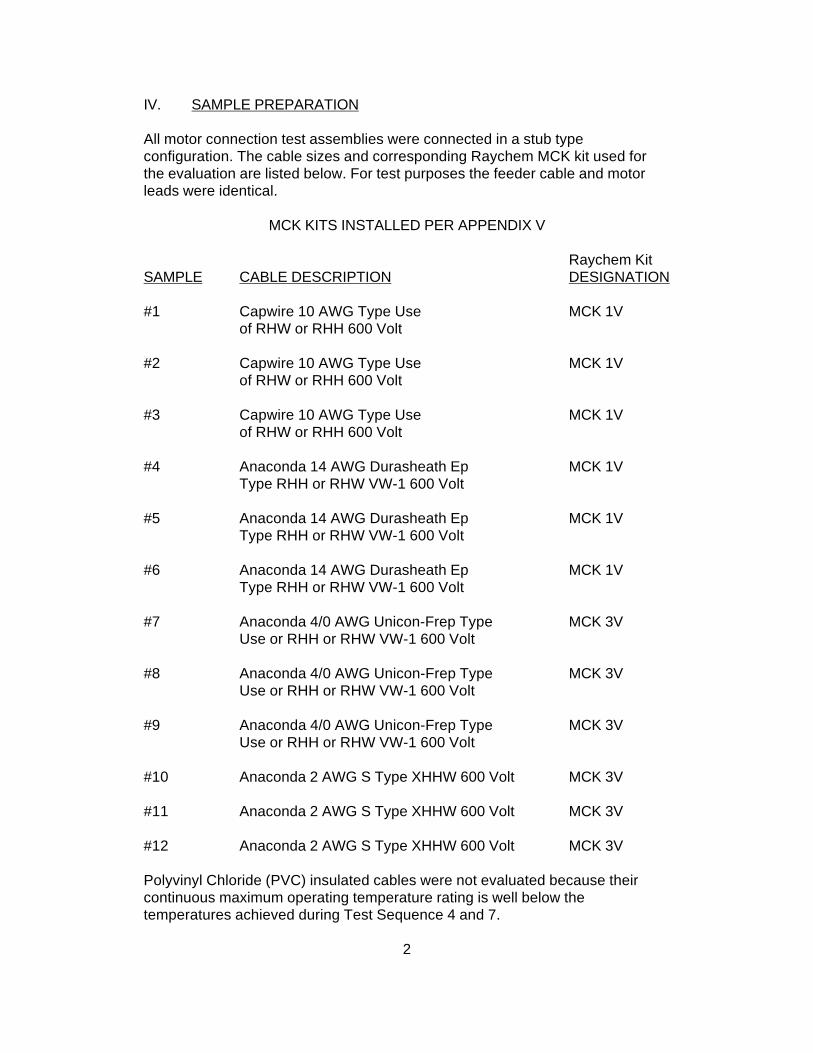
IV. SAMPLE PREPARATION
All motor connection test assemblies were connected in a stub typeconfiguration. The cable sizes and corresponding Raychem MCK kit used forthe evaluation are listed below. For test purposes the feeder cable and motorleads were identical.
MCK KITS INSTALLED PER APPENDIX V
Raychem KitSAMPLE CABLE DESCRIPTION DESIGNATION
#1 Capwire 10 AWG Type Use MCK 1Vof RHW or RHH 600 Volt
#2 Capwire 10 AWG Type Use MCK 1Vof RHW or RHH 600 Volt
#3 Capwire 10 AWG Type Use MCK 1Vof RHW or RHH 600 Volt
#4 Anaconda 14 AWG Durasheath Ep MCK 1VType RHH or RHW VW-1 600 Volt
#5 Anaconda 14 AWG Durasheath Ep MCK 1VType RHH or RHW VW-1 600 Volt
#6 Anaconda 14 AWG Durasheath Ep MCK 1VType RHH or RHW VW-1 600 Volt
#7 Anaconda 4/0 AWG Unicon-Frep Type MCK 3VUse or RHH or RHW VW-1 600 Volt
#8 Anaconda 4/0 AWG Unicon-Frep Type MCK 3VUse or RHH or RHW VW-1 600 Volt
#9 Anaconda 4/0 AWG Unicon-Frep Type MCK 3VUse or RHH or RHW VW-1 600 Volt
#10 Anaconda 2 AWG S Type XHHW 600 Volt MCK 3V
#11 Anaconda 2 AWG S Type XHHW 600 Volt MCK 3V
#12 Anaconda 2 AWG S Type XHHW 600 Volt MCK 3V
Polyvinyl Chloride (PVC) insulated cables were not evaluated because theircontinuous maximum operating temperature rating is well below thetemperatures achieved during Test Sequence 4 and 7.
2

V. TESTING
A. Test Sequence
1. Immersion
The test samples were immersed for 24 hours so that the entire motorconnection area was submerged under a minimum one foot head of tap waterhaving an ambient temperature of 23 C + 3 C.
2. Insulation Resistance - After Immersion
Insulation Resistance was measured after 24 hours immersion by applying 500volts D.C. between each conductor and the grounded water bath for one minute.
Requirement: 2.5 x 10⁶ ohms minimum.
Results: All samples passed. Values are recorded in Appendix I.
3. A.C. Withstand - After Immersion
Following the Insulation Resistance Measurement, an A.C. Voltage (60 hertz) of2.2kV was applied between each conductor and the grounded water bath forone minute.
Requirement: No breakdown or flashover.
Results: All samples passed.
4. Heat Conditioning
The test samples were placed in an air circulating oven at a temperature of 90°Cfor a period of 72 hours.
5. Insulation Resistance - After Heat Conditioning
Insulation Resistance was measured after Heat Conditioning as described inTest Sequence 2.
Requirement: 2.5 x 10⁶ ohms minimum.
Results: All samples passed. Values are recorded in Appendix II.
3

6. A.C. Withstand - After Heat Conditioning
An A.C. Voltage of 2.2kV was applied between each conductor and thegrounded water bath for one minute following the Insulation ResistanceMeasurements.
Requirement: No breakdown or flashover.
Results: All samples passed.
7. Thermal Cycling
The test assemblies were subjected to 50 cycles of current heating followed byimmersion. One cycle is defined as applying sufficient current to the assembliesto achieve a conductor temperature of 90°C for one hour, then de-energizing thesamples and within three minutes immersing the motor connection portion of theassemblies under a minimum one foot head of tap water having an ambienttemperature of 23°C + 3°C for 30 minutes.
8. Insulation Resistance-After 25th and 50th Thermal Cycles
Insulation Resistance was measured after the 25th and 50th thermal cycles asdescribed in Test Sequence 2.
Requirement: 2.5 x 10⁶ ohms minimum.
Results: All samples passed. Values are recorded in Appendix III.
9. A.C. Withstand-After 25th and 50th Thermal Cycles
Each assembly was subjected to an A.C. Voltage Withstand after the 25th and50th Thermal Cycles as described in Test Sequence 3.
Requirement: No breakdown or flashover.
Results: All samples passed.
10. A.C. Leakage Current Measurement
Leakage current was measured by applying an A.C. Voltage of 600 voltsbetween each conductor and the grounded water bath for one minute whileimmersed per Test Sequence 1.
Requirement: 2.5mA maximum.
Results: All samples passed. Values are recorded in Appendix IV.
4

11. A.C. Withstand - Final
The motor connection assemblies were subjected to a final A.C. Withstandwhich consisted of applying an A.C. voltage of 9.5kV between each conductorand the ground water bath for 15 minutes while immersed per Test Sequence 1.
Requirement: No breakdown or flashover.
Results: All samples passed.
12. D.C. Withstand
Each sample was subjected to a D.C. Withstand by applying a D.C. Voltage of34.5kV between each conductor and grounded water bath for five minutes whileimmersed per Test Sequence 1.
Requirement: No breakdown or flashover.
Results: All samples passed.
5

APPENDIX I
INSULATION RESISTANCE MEASUREMENTS-500 VOLTS D.CAFTER INITIAL IMMERSION
Requirement: 2.5 x 10⁶ ohms minimum.
SAMPLE NO. INSULATION RESISTANCE (Ohms)1 3.0 x 10¹³
2 2.0 x 10¹³
3 2.8 x 10¹³
4 5.0 x 10¹²
5 5.0 x 10¹²
6 5.8 x 10¹²
7 4.0 x 10¹²
8 2.0 x 1o12
9 1.0 x 10¹²
10 2.0 x 1o12
11 5.0 x 1o12
12 2.0 x 10¹²

APPENDIX II
INSULATION RESISTANCE-500 D.CAFTER HEATING CONDITIONING
Requirement: 2.5 x 10⁶ ohms minimum.
SAMPLE NO. INSULATION RESISTANCE (Ohms)1 2.2 x 10¹³
2 2.0 x 10¹³
3 2.4 x 10¹³
4 1.0 x 10¹³
5 7.0 x 10¹²
6 4.5 x 10¹²
7 4.0 x 10¹²
8 4.5 x 10¹²
9 5.6 x 10¹²
10 7.0 x 10¹²
11 6.2 x 10¹²
12 9.0 x 10¹²

APPENDIX III
INSULATION RESISTANCE-500 VOLTS D.CAFTER 25TH AND 50TH THERMAL CYCLES
Requirement: 2.5 x 10⁶ ohms minimum.
SAMPLE NO. 25TH CYCLE 50TH CYCLE1 2.0 x 10¹⁴ 2.0 x 10¹³
2 2.0 x 10¹⁴ 1.1 x 10¹³
3 5.0 x 10¹³ 9.2 x 10¹²
4 4.5 x 10¹² 5.2 x 10¹²
5 4.0 x 10¹² 4.5 x 10¹²
6 4.5 x 10¹² 4.5 x 10¹²
7 1.3 x 10¹² 1.9 x 10¹²
8 1.5 x 10¹² 3.0 x 10¹²
9 1.8 x 10¹² 3.0 x 10¹²
10 6.8 x 10¹² 1.8 x 10¹²
11 4.2 x 10¹² 3.4 x 10¹²
12 4.5 x 10¹² 4.0 x 10¹²

APPENDIX IV
A.C. LEAKAGE CURRENT MEASUREMENTS
Requirement: 2.5mA maximum.
SAMPLE N0. A.C. LEAKAGE CURRENT
1 .038mA
2 .039mA
3 .036mA
4 .036mA
5 .035mA
6 .037mA
7 .120mA
8 .130mA
9 .150mA
10 .150mA
11 .150mA
12 .165mA


EDR-50102/21/80
1.0 OBJECTIVE
To evaluate the performance of Raychem type MCK-5 heat shrinkable stub and in-line splices in terminal boxes of motors rated through 8.7kV.
A total of eighteen MCK-5 samples were evaluated. The first group of twelve test samples went through a series of electrical voltage withstands followed by a long-term overvoltage test. The second group of six test samples went through a similar series of electrical voltage withstands followed by a thermal and water immersion cycling test.
All kits were subjected to rated ampacities per the National Electric Code, Article 310-38 for 90°C continuous rated feeder cables.
All samples passed the designed test criteria. The test results are summarized in Table I.
3.0 CONCLUSION
The test program results indicate that the MCK-5 performed successfully as an environmentally sealed insulation system for application on motor-feeder cables rated up to 8.7kV AC.
1

EDR-50102/21/80
4.0 SAMPLE DESCRIPTION
4.1 Cables and Connections
Feeder cables were chosen for electrical tests on the basis of nominal diameter and in such a manner that when connected to a sample motor lead would represent the largest cross-section for which the MCK-5 was designed (Group I samples).
Immersion test samples were chosen such that feeder and motor leads were the same size to allow for maximum heat generation in the butted connection (Group II samples).
All medium voltage cables were terminated using the Raychem HVT termination system.
Connectors used were of the compression type, short barrel, single bolt, as manufactured by either Penn-Union (Series TLU) or by Burndy Corporation (Series YA).
Connection hardware was either 3/8 or 1/2 inch, as appropriate, with bolt lengths chosen not to extend through the nut by more than 1/4-inch.
4.2 Sample Preparation
The MCK-5 samples were assembled in accordance with the standard installation instructions as provided in each kit. The test sample matrix used in the evaluation is given in Table II.
3


EDR-50102/21/80
5.0 TESTING
All eighteen MCK-5 samples were first subjected to a test sequence consisting of applicable sections of IEE-404, 1977, "IEEE Standard for Power Cable Joints". The tests included Discharge Extinction Voltage, AC and DC Voltage Withstand, and Impulse Voltage Withstand. The samples were then divided into two groups. Group I consisting of twelve samples underwent long-term overvoltage tests. Group II consisting of six samples were immersion cycled. The cycling consisted of one hour heating in air by current induction, followed by immersion for one-half hour under two feet of water at 23°C + 3°C.
The current used was the specified allowable ampacity for 90°C continuous rated insulated single copper conductor isolated in air (NEC Article 310-38). For the 2/0 copper conductor the current was 350 amperes, calculated for an ambient air temperature of 25°C. The alternating heating and cooling of the samples was performed in accordance with Section 3.3.10 "Current Cycle and Water Submersion Test" of ANSI Cll9.1, 1974 for "Sealed Insulated Underground Connector Systems".
5

EDR-50102/21/80
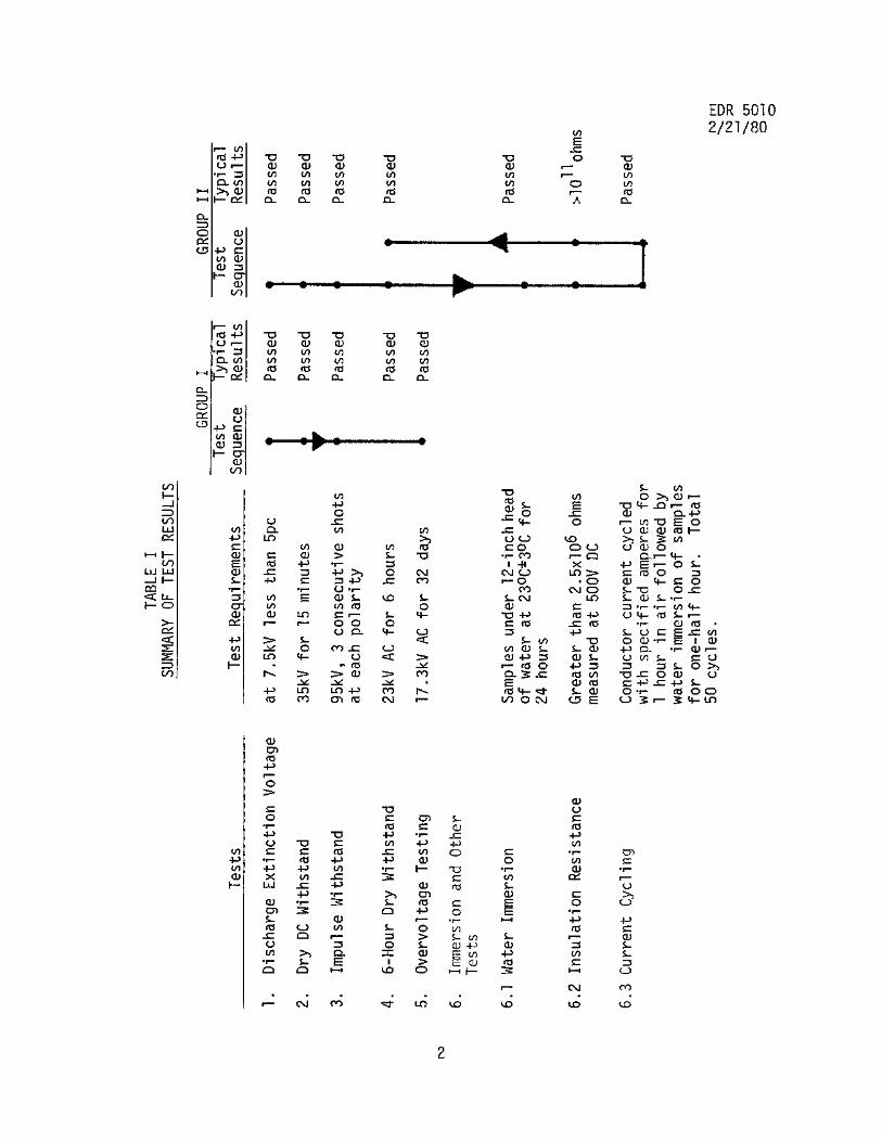
6.0 TEST RESULTS
All samples went through the following sequence of tests.
6 1 Discharge Extinction Voltage
Test voltages were raised above their recommended values (IEEE-404-1977) and then lowered until discharges below 5pc were observed. Result: All samples passed or exceeded test requirements of 7.5kV discharge free operation (less than 1/2pc) with a minimum ground plane separation of one-half inch. (For MCK's in intimate contact with ground plane, refer to Notes, Section 7.1)
6.2 15-Minute Dry DC Withstand (per IEEE-404-1977)
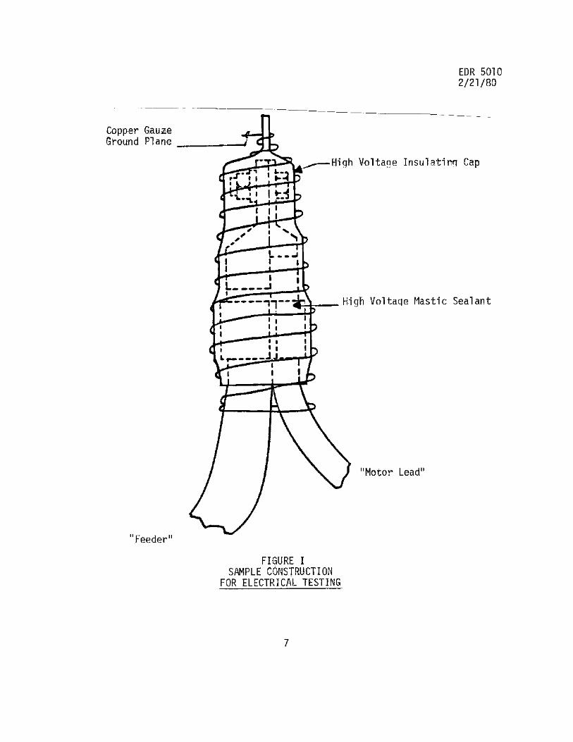
A DC voltage of 35kV was applied for 15 minutes between conductor and a copper gauze ground plane which was wrapped tightly around the sample, see Figure I.
Result: All samples passed with no breakdown or flashover.
6.3 Impulse Voltage Withstand(per IEEE-404-1977)
A nominal 1.2x50 ,µs wave of 95kV was applied between conductor and the copper gauze ground plane. The samples were required to pass 3 consecutive shots of each polarity.
Result: All samples passed with no flashover or breakdown.
6

EDR-50102/21/80
6 4 6-Hour Dry Withstand (per IEEE-404-1977)
A 60-hertz voltage of 23kV was applied for 6 hours betweenconductor and the copper gauze ground plane.
Result: All samples passed with no flashover or breakdown.
6.5 Long-Term Overvoltage Tests
A 60-hertz voltage of 17.3kV was applied for 32 days between conductor and the copper gauze ground plane. The voltage of 17.3kV represents 3.5 times normal operating voltage to ground, and by operating for over 32 days gives an extrapolated equivalent service life at rated voltage of over 40 years.
Result: All twelve Group I samples passed with no flashover or breakdown occurring.
6.6 Immersion Test (per ANSI Cll9.1, 1974, Sect. 3.3.10)
All six Group II samples were then connected in series and subjected to the following sequence of tests: 6.6.1 Spliced samples were immersed under a 12-inch head of tap water at 23°C + 3°C for 24 hours. 6.6.2 Insulation resistance measurements were taken on immersed samples between conductor and the grounded water bath using a megohmmeter set at 500V DC.
Result: Nominal value of 8 samples: 8 x 10¹¹ohms.
8

EDR-50102/21/80
6.6.3 The samples were current cycled for one hour with 350 amperes and then immersed for one-half hour in 23°C + 3°C tap water. The samples went through a total of 50 cycles.
6.6.4 Insulation resistance measurements were taken after the 25th and 50th cycle.
Results: Nominal value of 8 samples: 7 x 10¹¹ ohms.
6.6.5 After completion of the 50 current cycles, the Group II samples were further subjected to a 6-hour withstand test at 23kV AC.
Results: All samples passed without flashover or breakdown.
9

EDR-50102/21/80
7.0 NOTES
7.1 Discharge Extinction Voltage
Experiments were conducted using various air gaps between the MCK-5 and ground to determine the minimum required clearance so that the 5-8kV shielded power cable connection exhibited a maximum of 5 picocoulombs of discharge at 1.5 times operating voltage (in this case 7.5kV). It was determined that with a ground clearance of 1/2 inch, the connection would operate discharge-free at over 1.5 times rated voltage.
Since, in practice, it is not possible to guarantee clearances between all points on a stub splice and all points in the interior of a motor conduit box, long-term overvoltage tests were conducted which showed that the continuous presence of discharges did not have any deleterious effects on the performance of the Raychem MCK-5, even when in intimate contact with ground.
10