mctc manual - buechler
TRANSCRIPT

MCTC manual
Software version : 2.11.x Manual revision : rev.00 Language : ENG Date : February 2021

2 MCTC manual
Index 1 Introduction 4
Symbols 4 Terms 4 Transport 4 Receipt 4 Disclaimer 4
2 General information 5 Safety 5 Certification 5 Operating environmental conditions 5
3 General operation 6 The Interface 6
3.1.1 MCTC Touchscreen 6 3.1.2 MC-BC Blind controller 7
Start-up & Login 8 3.2.1 Configuration wizard 8 3.2.2 Home screen 8 3.2.3 Help function 9 3.2.4 User levels 9
System Configuration 10 The MCTC production screen 16
3.4.1 Injection Molding mode 16 3.4.2 Extrusion mode 17 3.4.1 Batch Mode 18
System performance 19 3.5.1 General 19 3.5.2 MCBalance, MCPowder, MCHigh Output and MCLiquid 19 3.5.3 MCHybrid 20
Quick start configuration after system reset 21 Material files 22 Recipe function 23
3.8.1 Material functions 23 3.8.2 Calculations 23 3.8.3 Calculation examples 24 3.8.4 Recipe editor screen 25 3.8.5 Creating a new recipe 26 3.8.6 Load / edit a recipe 26 3.8.7 Deleting a recipe 27
Tools Menu -NEW- 28 3.9.1 Fill System 28 3.9.2 Prime 28 3.9.3 Purge 28 3.9.4 One Shot 28
Purge function -NEW- 28 3.10.1 Configure the purge functionality 29 3.10.2 Setting the required purging RPM 30 3.10.3 Adjusting the purge motor speed 30 3.10.4 Purge recipe function 30 3.10.5 Using the purge function 31
Customer Support -NEW- 32 USB menu 33
3.12.1 Export and Backup / Restore 33 3.12.2 MCSmart USB logging 33 3.12.3 Remove USB stick 34 3.12.4 Insert USB memory stick 34
Consumption counters 35 3.13.1 Consumption counter by order 35

3 MCTC manual
Consumption report 36
4 Events 37 General 37 Configuration 37 Active events 38 Operator events 38 Alarm history 38 Events 38
4.6.1 System events 38 4.6.2 Group events 38 4.6.3 Unit events 39 4.6.4 Component events 39
5 System 40 Main Material Sensor 40
5.1.1 Alarm settings 40 5.1.2 Electrical connections 40
6 Batch mode 41 Batch mode component configuration 41
6.1.1 Batch Settings 42 6.1.2 Batch unloading 42
Batch mode production screen 43 Connection examples batch unloading 44
6.3.1 Example 1 – Batch with unloading controlled manually 44 6.3.2 Example 2 – Batch with unloading controlled by MCTC 44 6.3.3 Example 3 – Batch with unloading option activated by pushbutton 45
7 MCTwin 46 Introduction 46 Closed loop 47
7.2.1 Configuration 48 7.2.2 Production 50
Open Loop 52 7.3.1 Production 53
8 Multi component 55 MCTC multi component controller 55 Group structure 56 MCBC blind controller 57 CAN bus connection 58 Alarm/warning output 58 Unit controller addressing 59 MCTC remote setup 60 Multi component production 61
8.8.1 Injection molding - gravimetric mode 61 8.8.2 Extrusion - gravimetric mode - tacho 62 8.8.3 Extrusion - gravimetric mode - relay 63
9 Outputs 64 MCBalance, MCPowder, MCHigh Output, MCLiquid 64 MCHybrid 65
10 Trouble shooting 66
APPENDIX A: MCTC Technical Specifications 67
APPENDIX B: MCTC Dimensional drawing 68
APPENDIX C: Standard electrical connections 69
APPENDIX D: Declaration of conformity 70

4 MCTC manual
1 Introduction Thank you for purchasing a Movacolor metering device. This manual is addressed to operators and qualified technicians taking care of the metering of dry additives to ensure correct use of the Movacolor dosing unit. This manual must be read before installing the dosing unit. Keep this manual in a place accessible for all operators.
Symbols
Important note.
Attention; safety regulations for the operator.
Terms
Operator: A person charged to operate, adjust, maintain and clean the machine. Qualified Technician: A specialized, suitable trained person authorized to execute the installation,
non-routine maintenance, or repairs requiring special knowledge of the machine and how it operates.
Multi component: Two or more dosing systems on one machine.
Transport To protect the Movacolor unit against damage during transport, the unit is packed in a cardboard box filled with polyurethane foam. Delivery terms are Ex-Works Sneek, The Netherlands. Buyer is responsible for the transport. Movacolor cannot be held liable for any damage during transport.
Receipt Check the unit thoroughly upon receipt for damages or missing parts. Pass any remarks to the local agent or Movacolor within 8 days upon receipt of goods.
Disclaimer Movacolor does not warrant that the hardware or software will work properly in all environments and applications, and makes no warranty and representation, either implied or expressed, with respect to the quality, performance, merchantability or fitness for a particular purpose. Movacolor has made every effort to ensure that this user’s manual is accurate; Movacolor disclaims liability for any inaccuracies or omissions that may have occurred. Information in this user’s manual is subject to change without notice and does not represent a commitment on the part of Movacolor. Movacolor assumes no responsibility for any inaccuracies that may be contained in this user’s manual. Movacolor makes no commitment to update or keep the current information in this user’s manual, and reserves the right to make improvements to this user’s manual and/or to the products described in this user’s manual, at any time without notice. If you find information in this manual that is incorrect, misleading or incomplete, we would appreciate your comments and suggestions.

5 MCTC manual
2 General information
Safety
The equipment is only designed and may only be used for the dosing of dry additives.
Any use that is not in conformity with the instructions is considered improper and as such frees the manufacturer from any liability regarding damage to things and/or persons.
Before switching on the unit for the first time, ensure that the mains power voltage applied is between 95 and 250VAC.
Ensure that all parts are securely fixed to the extruder, injection molding machine or machine support.
Always switch off the Movacolor control cabinet and disconnect the mains power plug from electrical power before performing maintenance.
Dangerous voltages are present inside the control cabinet for up to 2 minutes after it has been
switched off. Always disconnect the main compressed air connection before performing maintenance.
Certification
The Movacolor dosing unit is designed and produced in conformity with the following European regulations:
1. standards for machinery (health, safety, environment). 2. EMC (electromagnetic compatibility). 3. 2006/42/EG. 4. RoHS.
Operating environmental conditions
1. The unit must be protected against weather conditions. 2. Operating temperature -20 to +70 degrees Celsius. 3. Protection class: IP-50.
6 MCTC manual
3 General operation
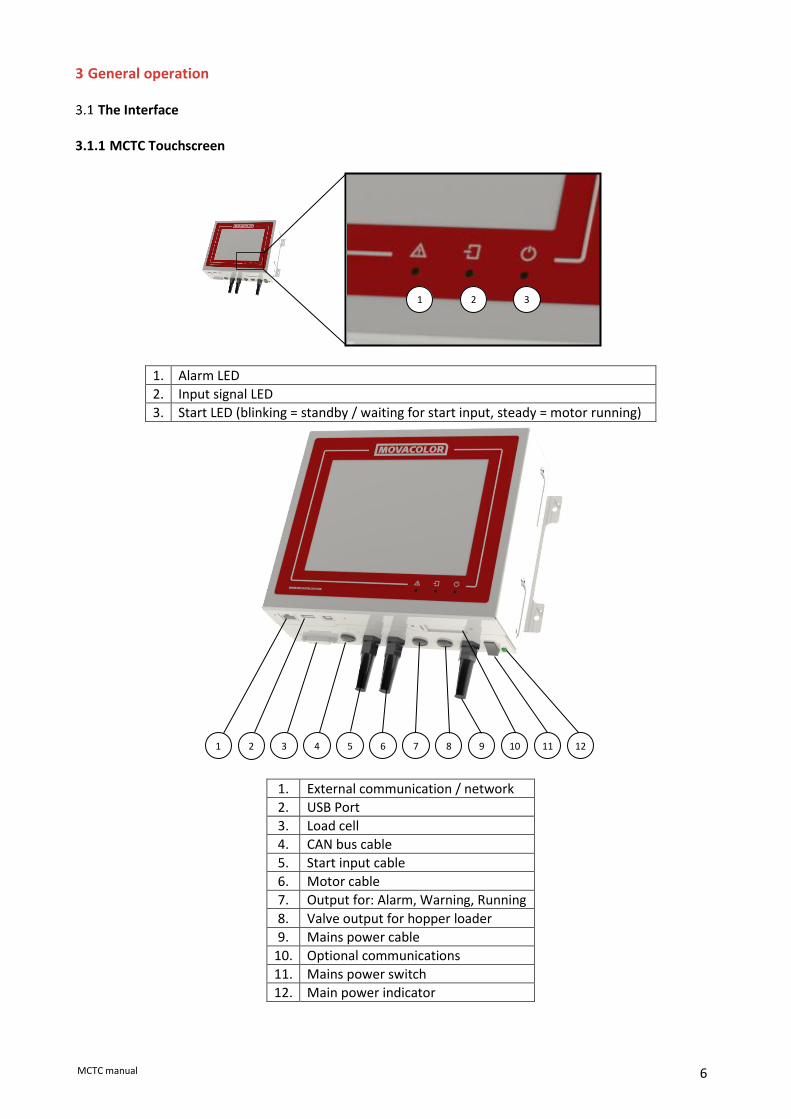
The Interface 3.1.1 MCTC Touchscreen
1. Alarm LED
2. Input signal LED
3. Start LED (blinking = standby / waiting for start input, steady = motor running)
1. External communication / network
2. USB Port
3. Load cell
4. CAN bus cable
5. Start input cable
6. Motor cable
7. Output for: Alarm, Warning, Running
8. Valve output for hopper loader
9. Mains power cable
10. Optional communications
11. Mains power switch
12. Main power indicator
3 2 1
2 3 4 5 6 7 11 9 8 10 1 12

7 MCTC manual
3.1.2 MC-BC Blind controller The image below shows the MC-BC in a standard configuration. In multicomponent or remote setups, refer to chapter Multicomponent.
1. Load cell
2. CAN bus cable
3. Motor cable
4. Valve output for hopper loader
5. Mains power cable
6. Mains power switch
7. Mains power indicator
7 6 5 4 3 2 1

8 MCTC manual
Start-up & Login After switching on the mains power of the MCTC, the screen will remain black for about 15 seconds, followed by various loading screens. After about 90 seconds the home screen appears. When the unit is used for the first time, a Configuration Wizard appears. 3.2.1 Configuration wizard When the machine is powered up for the first time a configuration wizard will pop up. In this wizard, the date/time can be set and a weight tare can be done for each unit. For the weight tare, it is necessary to have the unit(s) installed as they will be during production, but not yet filled with material. Weight tare does not improve the dosing accuracy. If the dosing accuracy is a problem, please perform a loadcell calibration.
3.2.2 Home screen
Single component Multi component
9 MCTC manual
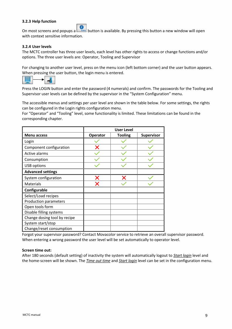
3.2.3 Help function
On most screens and popups a button is available. By pressing this button a new window will open with context sensitive information. 3.2.4 User levels The MCTC controller has three user levels, each level has other rights to access or change functions and/or options. The three user levels are: Operator, Tooling and Supervisor For changing to another user level, press on the menu icon (left bottom corner) and the user button appears. When pressing the user button, the login menu is entered. Press the LOGIN button and enter the password (4 numerals) and confirm. The passwords for the Tooling and Supervisor user levels can be defined by the supervisor in the “System Configuration” menu.
The accessible menus and settings per user level are shown in the table below. For some settings, the rights can be configured in the Login rights configuration menu. For “Operator” and “Tooling” level, some functionality is limited. These limitations can be found in the corresponding chapter.
User Level
Menu access Operator Tooling Supervisor
Login Component configuration Active alarms Consumption USB options Advanced settings
System configuration Materials Configurable
Select/Load recipes
Production parameters
Open tools form
Disable filling systems
Change dosing tool by recipe
System start/stop
Change/reset consumption
Forgot your supervisor password? Contact Movacolor service to retrieve an overall supervisor password. When entering a wrong password the user level will be set automatically to operator level. Screen time out: After 180 seconds (default setting) of inactivity the system will automatically logout to Start login level and the home-screen will be shown. The Time out time and Start login level can be set in the configuration menu.

10 MCTC manual
System Configuration For initial setup, or a big change in the setup, the MCTC controller needs to be configured. This can be done manually by the changing the settings of the system, or by using the configuration wizard. Both options can be found in the “System Configuration” menu (only accessible for Supervisor), to enter this menu press:
To start the configuration wizard press , and follow the steps of the wizard. The following settings are for the entire system and there for need to be altered once. It is not possible to change these settings for each separate configured component. For component specific configuration (MCBalance, MCHigh Output, MCWeight, MCLiquid, MCNexus, MCNumera, MCPowder, MCHybrid) see the device specific chapters. For multicomponent setups ( 2 or more components) refer to chapter Multi component. Language : ENG - DE - FR - …… Production mode : INJ – EXT - BATCH Input type : Timer - Relay - Tacho Auto start : OFF - ON Startup login : Operator - Tooling – Supervisor Login Rights : Login rights configuration menu Tooling passw. : xxxx 1111 Supervisor passw. : xxxx 2222 IP address : 0.0.0.0 (For example: 192.168.1.100) Netmask : 0.0.0.0 (For example: 255.255.255.0) Gateway : 0.0.0.0 (For example: 192.168.1.1) Nameserver : 0.0.0.0 (For example: 8.8.8.8) MCSmart IP Address : 0.0.0.0 (For example: 192.168.1.10) Screen Time Out : OFF - ON Date / Time : (dd / mm / yy) (hh / mm) Device name : MCTC Number of groups : 1-15 Group configuration : Group configuration menu Recipe enabled : ON – OFF Purge enabled : OFF – ON Setpoint units : % - Parts Display units : % - Parts – g/s – kg/h Imperial units : OFF - ON I/O module: : NONE - ANALOG - PRO.BUS - PRO.NET* Modbus Device Address : 1-231 Line Control : OFF – ON* * For extra options, please refer the corresponding manual. System Configuration: Language The standard language is English. If your language is not listed you can put a request at your local Movacolor representative for a translation. System Configuration: Production mode Selection of type of process in which the Movacolor dosing system is used. Extrusion (EXT), Injection Molding (INJ) or Batch.

11 MCTC manual
System Configuration: Input type Type of input signal used for synchronizing the dosage: relay, timer or tacho.
In VOLU prod. Mode. Timer is used automatically.
For INJ in timer mode the start pulse should be min. 0,2 seconds. For INJ in relay mode the start signal should be as long as the dosing time. If INJ - Relay is selected the dosing system will follow the machine relay time. The controller will filter out small changes so that the regulation is not being influenced. Big changes will be followed, the production screen shows the real machine relay time. Input (start) signal The MCTC needs an input signal from the production machine in order to operate. Three different input signals can be used to control the MCTC. Please also have a look at chapter Electrical Connections. WARNING: make sure the input signals of different units are not connected to each other. This might cause damage to the controller. 1. A potential free relay contact.
Use the white and brown wire of the input cable for the potential free contact. 2. A potential contact (24 Volt DC*).
In case of a powered relay signal (wet contact) connect the white wire to +24 VDC and the yellow wire to the 0 VDC. * Note potential contact Guaranteed OFF: 0-8VDC Guaranteed ON: 18-30VDC
3. A tacho signal up to 30 Volt DC. This is used when the dosing system needs to be connected to an extruder that has a tacho generator that produces a voltage linear to the extruder speed. When using a tacho generator signal, make a connection between the white and brown wire. It will function as a start signal. Connect green to + VDC and yellow to the - side of the generator.
The maximum voltage that can be applied to the MCTC is 30 VDC. The tacho voltage has to be reduced to 30 VDC if the tacho generator has a higher voltage output than 30 VDC at the maximum extruder output capacity. See the diagram below. Rx (kilo-Ohm) = (2,684 x (Max. tacho output VDC – 5)) – 66 If the extruder stops when connected to the metering unit, an isolated signal converter is needed. Contact your agent or Movacolor for more information.
EXT INJ BATCH
timer X X
relay X X X X
tacho X X
GRAVI VOLU GRAVI VOLU
Input connection
Resistor (Rx) kOhm Green wire + Tacho
generator EXTRUDER Yellow wire -
8
7

12 MCTC manual
Tacho function: The tacho function is only available in extrusion mode. This function can be used with extrusion when it is necessary that the dosing rate is automatically adjusted to the extruder speed. In tacho mode an input voltage is linked to a dosing speed setting. If the extruder speed changes, the tacho input voltage and speed of the dosing unit will change accordingly. A linear correlation between extruder speed (tacho input signal) and the needed dosing speed is assumed. See graph.
The tacho function can be set in the production screen and can be set manually or be synchronized: Manual: Fill in the voltage the tacho produced by the tacho generator at maximum extruder speed. Synchronize: Let the extruder run and select synchronize. The tacho voltage P1 will be taken over automatically, enter the actual extruder capacity. This is linked to the set motor speed P2 (in RPM mode) or calculated motor speed (in GRAVI mode). During production, the motor speed P2 can be changed. The new speed is linked to the previous stored voltage and the graph will change accordingly. During production, the voltage P1 can be adjusted to the current tacho input voltage (manually or automatically) as shown above. The new voltage is linked to the previous stored extruder capacity and the graph will change accordingly.
• The maximum voltage that can be applied to the MCTC tacho input is 30 VDC;
• The tacho signal must be a clear signal. Any failure in the voltage signal will be followed by dosing variations.
In case of a MCWeight, input type needs to be set to relay!
System Configuration: Auto start Enable / disable auto start up after voltage dip or mains power has been switched OFF. When enabled the unit will continue dosing automatically after a Voltage dip or mains power has been switched OFF and ON again. System Configuration: Startup login User level to start up with, when switching on the controller’s mains power. Operator, Tooling or Supervisor. This is the level to which the controller will switch back at screen time-out.
Tacho input voltage (VDC)
Extr
ud
er c
apac
ity
(kg/
h)
Tacho graph (Example)

13 MCTC manual
System Configuration: Login Rights configuration menu In this menu, the Login level rights of some functionality can be changed.
System Configuration: Tooling password Password for Tooling user level, 4 numerals, default 1111.
System Configuration: Supervisor password Password for Supervisor user level, 4 numerals default 2222. System Configuration: IP address IP-address for use in a network environment (TCP/IP protocol). (For example 192.168.1.100) When the Movacolor dosing system is part of a network, the controller must have an IP-address for identification. This IP-address has to correspond with the IP-address of your computer. Ask your network administrator for a unique address.
System Configuration: Netmask Netmask for use in a network environment (TCP/IP protocol). (For example 255.255.255.0) When the Movacolor dosing system is part of a network, the controller must have a Netmask for accessing the TCP/IP network.
System Configuration: Gateway Gateway address for use in a network environment (TCP/IP protocol). (For example 192.168.1.1) When the Movacolor dosing system is part of a network, the controller must have a Gateway for accessing the TCP/IP network. This Gateway-address has to correspond with the Gateway-address of your computer. Ask your network administrator for the correct gateway setting.
System Configuration: Nameserver
The nameserver setting sets the IP address of the to use DNS Server. This is only needed when a fixed IP
address has been set and the use of the customer support function is needed. When setting a fixed IP
address, the nameserver will by default be set to the 8.8.8.8 public free DNS server from Google.
System Configuration: MCSmart IP Address IP Address of the computer where MCSmart agent software is active. MCSmart is a monitoring, logging, reporting PC software application. See MCSmart manual for more details. System Configuration: Screen Time out This button can be used to enable or disable the screen time out. If set to ON, the screen time out time can be set, as well as the screen backlight level. If enabled, the user level will reset to operator and the unit will navigate to the production screen, after the time out time has elapsed.
14 MCTC manual
System Configuration: Date / Time Actual date (dd / mm / yy), Actual time (hh / mm). Date and Time will be stored for approx. 5 years with controller switched OFF.
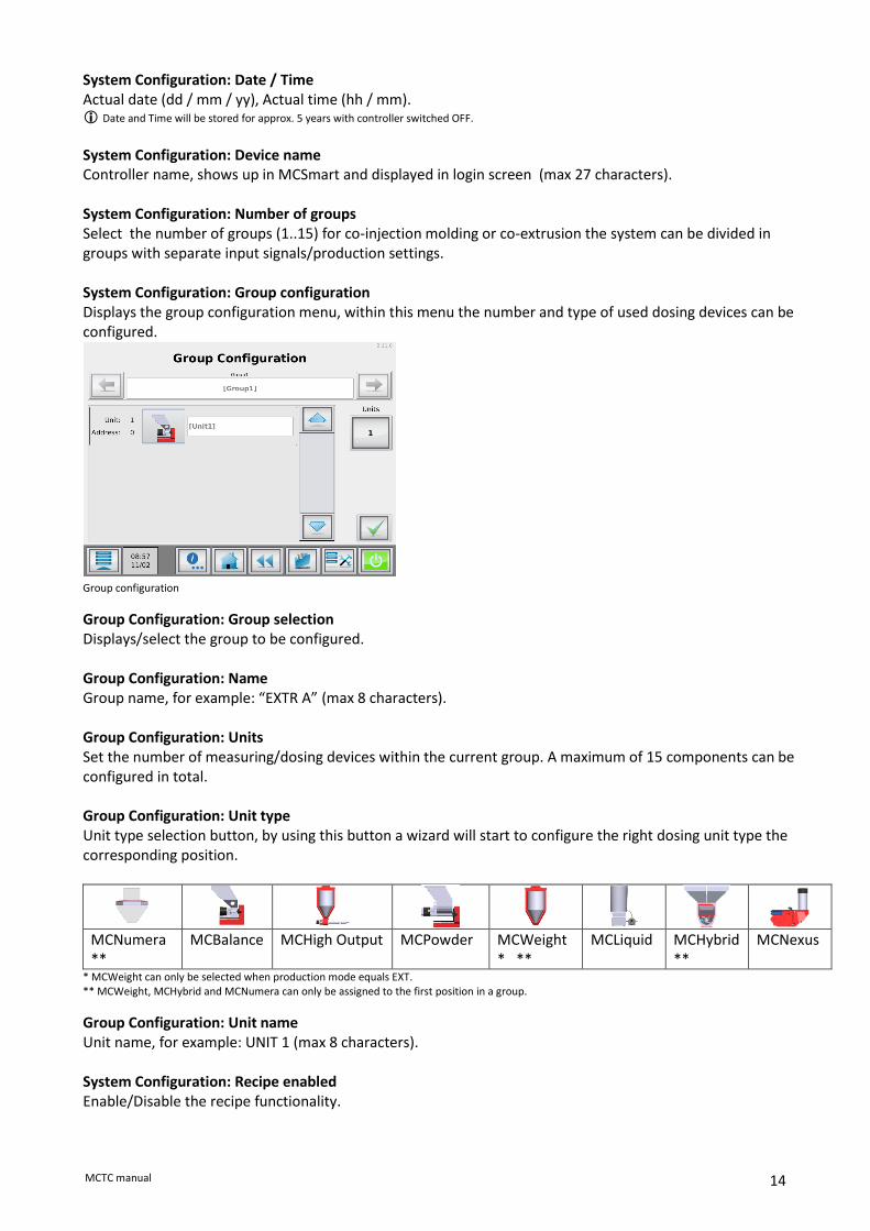
System Configuration: Device name Controller name, shows up in MCSmart and displayed in login screen (max 27 characters). System Configuration: Number of groups Select the number of groups (1..15) for co-injection molding or co-extrusion the system can be divided in groups with separate input signals/production settings. System Configuration: Group configuration Displays the group configuration menu, within this menu the number and type of used dosing devices can be configured. Group configuration
Group Configuration: Group selection Displays/select the group to be configured. Group Configuration: Name Group name, for example: “EXTR A” (max 8 characters). Group Configuration: Units Set the number of measuring/dosing devices within the current group. A maximum of 15 components can be configured in total. Group Configuration: Unit type Unit type selection button, by using this button a wizard will start to configure the right dosing unit type the corresponding position.
MCNumera **
MCBalance MCHigh Output MCPowder MCWeight* **
MCLiquid MCHybrid**
MCNexus
* MCWeight can only be selected when production mode equals EXT. ** MCWeight, MCHybrid and MCNumera can only be assigned to the first position in a group.
Group Configuration: Unit name Unit name, for example: UNIT 1 (max 8 characters). System Configuration: Recipe enabled Enable/Disable the recipe functionality.

15 MCTC manual
System Configuration: Purge enabled. Enable/Disable the purge functionality. System Configuration: Set point units Select the dosing set point input format, % of total or “parts of” (parts per hundred). System Configuration: Display units Select the output format of set values and actual values. For MCHybrid only % can be displayed. For MCHigh Output and MCWeight only kg/h are displayed. when imperial units enabled only %(parts) or lb/h can be selected.
System Configuration: Imperial units Imperial units, enable / disable. Set points and actuals displayed in lb/h or kg/h. System Configuration: I/O module Enable external communication, NONE, ANALOG, PROFIBUS or PROFIBUS (requires a special hardware extension board). Modbus TCP/IP is enabled by default.
System Configuration: Modbus Device address If the controller is used in a Modbus network, the unique identity can be filled in here (1-231).

16 MCTC manual
The MCTC production screen 3.4.1 Injection Molding mode
1. Material selection button. Through this button the material can be stored during production.
2. Percentage of additive to be dosed in relation to the entered shot weight.
3. Shot weight of the injection molding machine. Used for calculating the additive to be dosed.
4. Set dosing time (only visible in INJ – TIMER mode).
5. Tools menu. In this menu different settings can be made to the system. Check the “MCTC_Manual_General” for more detailed information.
6. Start/Stop button. When the button is colored green, the system is OFF (safe). In red condition the system is ON.
7. Toggle button. With this button you can toggle between the normal and the detailed view.
8. Actual RPM.
9. Actual Hopper weight.
10. Actual dosing time. Starting at the set time (4) and counting down to 0 seconds. Only visible in INJ - TIMER mode.
1 3
2 4
6 5
9
8
10 7

17 MCTC manual
3.4.2 Extrusion mode
1. Material selection button. Through this button the material can be stored during production.
2. Percentage of additive to be dosed in relation to the set extruder capacity.
3. Capacity of the extruder. Used for calculating the additive to be dosed. To be set by the user when the controller is in EXT – RELAY mode.
4. Tacho ratio button. Here you can link the applied voltage to a extruder capacity (only in EXT – TACHO mode)
5. Tools menu. In this menu different settings can be made to the system. Check the “MCTC_Manual_General” for more detailed information.
6. Start/Stop button. When the button is colored green, the system is OFF (safe). In red condition the system is ON.
7. Toggle button. With this button you can toggle between the normal and the detailed view.
8. Actual RPM.
9. Actual Hopper weight.
10. Actual tacho voltage.
1
2 3
4
5 6
7
8
9
10

18 MCTC manual
3.4.1 Batch Mode
1. Percentage of additive to be dosed in relation to the set batch weight.
2. Batch weight
3. Tools menu. In this menu different settings can be made to the system. Check the “MCTC_Manual_General” for more detailed information.
4. Start/Stop button. When the button is colored green, the system is OFF (safe). In red condition the system is ON.
Batch Mode MCNexus
1. Number of pellets to be dosed in one batch.
2. Start/Stop button. When the button is colored green, the system is OFF (safe). In red condition the system is ON.
3. Toggle button. With this button you can toggle between the normal and the detailed view.
4. Actual dosing
1
2
3 4
1 3
2
4

19 MCTC manual
System performance 3.5.1 General System performance can be characterized by the time it takes the component to reach the desired set point, the accuracy of the set point and the regularity of the material output. The algorithm is self-adjusting to the conditions and because the conditions vary, it cannot be predicted how long it will take the unit to adjust itself and reach a set point with certain accuracy. The following variables influence system performance: Material properties. Easy flowing, non-sticky and non-static material that comes in the form of small granules or powder can be dosed very accurate and regular. The accuracy and regularity of material output drops with increased granule size. However this is only a problem with extreme low outputs. 3.5.2 MCBalance, MCPowder, MCHigh Output and MCLiquid Periodical cleaning of the dosing cylinder and seals is necessary for proper operation. Extreme vibrations and shocks influence system performance noticeably. Normally the system will be able to compensate for vibrations and shocks. The dosing algorithm needs a certain time to weigh material loss and adjust the RPM accordingly. This time depends largely on the set point and the above mentioned two variables. The system constantly adjusts itself
to reach the best possible accuracy for current conditions. Over time it can reach an accuracy within 1% of the set point Under “normal” circumstances the unit will be more accurate than 10% after the first adjustment of the RPM. Before the unit makes its first RPM adjustment it might be running already very close to the desired set point because it uses a cylinder and material reference system to determine the first RPM setting. This accuracy however cannot be guaranteed because material properties can vary substantially from material to material. An unstable relay or tacho signal has a negative effect on the accuracy, repeatability and speed of the system because it will adjust to these parameter changes. A long cycle time combined with low dosage per shot can result in a slow system. Reset regulation
• Changing one parameter during production will cause the MCTC to adjust to the changes but it will not reset the regulation totally;
• Changing more production parameters during production within 10 seconds after each other will cause the MCTC regulation to reset. This is necessary for the system to adjust quickly to these big changes in the settings;
• Switching the power OFF and ON again will also cause the regulation to reset;
• Motor OFF and ON again will only cause the regulation to pause. The start-up RPM will be the same as the last RPM before the stop;
• Changing one parameter with motor OFF causes total reset of the regulation;
• With auto start = ON (CONFIGURATION <menu>) the motor follows the last status (motor Standby or motor Stop status) and causes total reset of the regulation.

20 MCTC manual
3.5.3 MCHybrid The dosing algorithm of the MCHybrid is a self-learning algorithm. The system adopts automatically to the material flow characteristics. Together with the default dosing characteristics related to the mounted and configured dosing valve, the system is able to learn and dose within 10% of its set point within about 3 batches. During system start up the material flow characteristics are unknown, to avoid overloading of the weighing bin the self-learning algorithm starts at 50% of the configured batch weight. As soon the material flow characteristics have been determined, 100% of the configured batch weight will be dosed. When the dosing accuracy cannot be met, a notification will arise mentioning the wrong dosing valve is used or configured. Extreme vibrations and shocks influence system performance noticeably. Normally the system will be able to compensate for vibrations and shocks. Changing set points during dosing of a batch will be adopted the next batch. Periodical cleaning of the dosing valves, weigh bin and mixer is necessary for proper operation. Reset regulation
• Reloading the material file resets the actual learned material flow characteristics;
• Switching the power OF and ON again will cause a total reset of the regulation.

21 MCTC manual
Quick start configuration after system reset
1
Login with supervisor level
2
Open system configuration menu
3
Press the configuration wizard and follow the steps, or follow the steps below.
4a
Select required operating mode (INJ, EXT, BATCH)
4b
Select required input type
4c
Configure the number of groups (1..15) If installed to one IMM or EXT set to “1”
5
Open the group configuration menu
5a
Set the number of units for the group
5b
Open the component types menu and select the right unit type for each position in the list
6
Confirm all screens
7
Open the device configuration menu
7a
Make all required settings, consult the appropriate chapter for setting the right settings (motor type, loader type, valves, etc.)
7b
Perform a load cell calibration (follow the onscreen instructions)
6 Ready for production!

22 MCTC manual
Material files To optimize the dosing system, the MCTC uses material files. These files contain information for different purposes and can be generated by the user. The information in a material file varies, depending on the type of dosing system which is used. For gravimetric units, the file contains information about the flow characteristics of the material. For optometric systems, the file contains information which can be used for consumption counting and dosing quantity. For each system, new material files can be generated by the user. For each dosing system type, this material file generation is explained in the dedicated operation chapter of the device. The Material files menu can be accessed by pressing the material name on the production screen (1), or by pressing the material name in the recipe menu (2). tooling or higher login required
1
2

23 MCTC manual
Recipe function With the MCTC it is possible to store the current production settings into a recipe. All production settings of all components will be stored within this recipe. An easy recall of the production settings is possible by loading a previous stored recipe. In case of a multi group configuration, one recipe includes all components and all groups. The Recipe function has to be enabled in the System Configuration screen. 3.8.1 Material functions The MCTC defines 4 different material types or component functions, each function represents another behavior in how the material dosing quantity is calculated/dosed. Add is only available in combination with Regrind.
V Virgin “Main material” or “Natural”
AddV Additive Virgin Amount additive material related to the amount of Virgin material
R Regrind Grinded end product containing the right mix of Virgin and Additives
Add Additive Amount additive material related to the Shotweight, Batch or total EXT capacity
Regrind is defined as “Grinded end product containing the right mix ratio of the required materials”. Other additives will be recalculated depending on the amount of Regrind added to the product mix. In the recipe editor the entered percentage of Regrind is not part of the 100% product mix. Required product mix Mix – Regrind ratio “Add” or Additive will be added to the product mix as specified in the recipe. The amount of material is based on the full shotweight, extruder throughput or batch and will not be changed / reduced by the amount of Regrind added. 3.8.2 Calculations The amount of dosed material is calculated with the following formulas:
Virgin 𝑉 = 𝐵𝐴𝑇𝐶𝐻 − 𝑅𝑒𝑔𝑟𝑖𝑛𝑑 − 𝐴𝑑𝑑 − 𝐴𝑑𝑑𝑉
AddV 𝐴𝑑𝑑𝑉 = (𝐵𝐴𝑇𝐶𝐻 − 𝑅) ∗ 𝐴𝑑𝑑𝑉%
Regrind 𝑅 = 𝐵𝐴𝑇𝐶𝐻 ∗ 𝑅%
Add 𝐴𝑑𝑑 = 𝐵𝐴𝑇𝐶𝐻 ∗ 𝐴𝑑𝑑%
BATCH can also be read as shotweight or kg/h

24 MCTC manual
3.8.3 Calculation examples Example 1: Single MCBalance unit, injection molding. Shotweight = 150gr, AddV = 5% AddV = 150gr * 5% = 7,5gr Virgin = 150gr – 7,5 gr = 142,5gr Example 2: Double MCBalance unit, injection molding. Shotweight = 250gr, AddV = 5%, Regrind = 25% Regrind = 250gr * 25% = 62,5gr AddV = (250gr – 62,5gr) * 5% = 9,4gr Virgin = 250gr – 62,5gr – 9,4gr = 178,1 gr Example 3: Triple MCBalance, shotweight 180gr, AddV = 2%, Add = 1%, Regrind = 20% Regrind = 180gr * 20% = 36gr Add = 180gr * 1% = 1,8gr AddV = (180gr – 36gr) * 2% = 2,9gr Virgin = 180gr – 36gr – 1,8gr – 2,9gr = 139,3gr Example 4: 3 component MCHybrid Batch weight = 500gr, C1 = Vrigin, C2 = 20% Regrind, C3 = 5% AddV 1 MCBalance inline dosing AddV = 2%. Shotweight 100gr. The mix to the injection molding machine will contain: Regrind = 100gr * 20% = 20gr AddV = (100gr – 20gr) * 5% = 4gr AddV = (100gr – 20gr) * 2% = 1,6gr Virgin = 100gr – 20gr – 4gr – 1,6gr = 74,4gr

25 MCTC manual
3.8.4 Recipe editor screen From the horizontal menu bar, press the recipe button: The Recipe editor screen will appear: Image is for reference only and can be different depending on the system configuration.
1. Recipe name Enter desired recipe name.
2. Injection molding Shot weight.
Extrusion Extruder throughput kg/h.
Batch Batch weight.
3. Injection molding (Timer only): Shot time.
Batch Unloading time
4. Component name Component name (can be set in configuration menu).
5. Pre-learned material curve Select the pre-learned material curve per component. In case of no pre-learned materials it is recommended to select the Movacolor default material file.
6. Material/component function how the material should be treated, regrind, virgin, additive.
7. Dosing percentage Enter dosing percentage per component. To disable a component (OFF), set the dosing percentage to 0%.
8. Group selection Select the current group to be edited. Only visible when more than one group configured.
9. Recipe browser Search and select existing recipes
10. QuickStart Start “quick start” wizard Only visible for single group configurations.
11. Dosing order Select the dosing order for available components Only available when a MCHybrid is configured.
12. Save button Save the recipe and load as active recipe.
13. Cancel leave this screen discarding all changes.
1
2 3
4 5 6
8
7
12
13
9
11
10

26 MCTC manual
3.8.5 Creating a new recipe A recipe can be created in three ways.
1) Saving the current production parameters 2) Entering the required production parameters in the recipe editor
3) Using the QuickStart button: 1) During production press the recipe button from the horizontal menu bar: The recipe editor screen will appear. Enter a recipe name and click the save button. The current recipe has been stored to the controller internal memory and will be applied immediately. 2) Open the recipe editor from the horizontal menu bar: Open the recipe browser window and select “new” Enter the required production parameter settings and choose a name for the recipe. Click the save button. 3) When using the QuickStart to generate a new Recipe, a wizard will come up. This wizard will generate a
new recipe. 3.8.6 Load / edit a recipe From the horizontal menu bar, press the recipe button: The Recipe editor screen will appear press the recipe list button (1).
Select the desired recipe by using the up and down buttons:
When there is a long list of stored recipes, it can be time consuming to find the recipe. It is possible to search in the list of recipes using the search button. You can enter part of the recipe name you
need to search for. Example, you need to load the recipe named “Recipe RED 1”, when you enter “RED” in the search field, all recipes names containing “RED” will be displayed in the list. Confirm the selection with the accept button: The next screen will show the settings of the selected recipe. Here you can check the settings of the recipe. By pressing the apply button the recipe will be loaded.
-OR-
Edit the production parameters within the recipe to your needs and save the recipe. To save the recipe, just press the save recipe button , you will be prompted to overwrite the recipe:
Overwrite current selected recipe (changes in the recipe will be saved). Do not overwrite, you will be prompted to enter a new recipe name (create a copy/new recipe).
The new recipe is not immediately selected, go back to the main recipe screen to select the new recipe.
A recipe can also be edited from the HOME screen. When a recipe is loaded and a production setting is changed, the recipe button icon will change to the following: By pressing this button, the recipe editor screen will be shown where you can decide to accept and save the changes to the current or a new recipe.
1

27 MCTC manual
3.8.7 Deleting a recipe From the HOME screen, press the recipe button, from the recipe editor screen choose the list button(1).
Select the desired recipe by using the up and down buttons:
To delete the selected recipe. To delete all recipes in the list at once.
1

28 MCTC manual
Tools Menu -NEW- The tools menu can be used to setup, prepare or empty a unit without the need for a supervisor login. By default, this menu is accessible for every login level, this can be changed in the system configuration menu.
3.9.1 Fill System On this tab, some changes to the fill system can be made:
(1) Disable filling This setting can be used to disable the loader of a unit.
(2) Start 1x fill Switching this button will start the loader to fill the hopper to the set hopper level once.
3.9.2 Prime On this tab, the dosing unit can be primed after it is filled with new material or when it has run empty. 3.9.3 Purge On this tab, the purge speed can be set if required. More detailed information about the Purge function can be found in the corresponding paragraph. 3.9.4 One Shot Only accessible by supervisor or higher login level. Production mode should be INJ – Timer.
A single shot can be dosed via this tab, the production settings from the production screen are used. Also the actual values (RPM and Dosing time) are displayed when this mode is activated.
Purge function -NEW- For most injection molding processes it is required to purge the machine barrel before production start. In case of a big barrel size related to the shot weight, it is required to purge with already colored material. With this purging function the dosing motor of the MCBalance can be started at a pre-set speed as long as the purge signal from the Injection Molding Machine is active. Be aware of the following remarks:
• Material dosed during purge is not counted by the MCTC consumption counters.
• The purge function is using VOLUMETRIC mode. There is no feedback on dosed amount of material.
• The speed of the dosing tool is set by the user, the user is responsible for entering the right RPM of the dosing tool used during purge.
• The right mix ratio of the end mix during purging cannot be guaranteed by Movacolor. Two types of purging are available: 1) Purging via Tools menu screen
This mode can be used to purge at any time by activating the purge mode through the Tools menu . Purging can be started with a purge signal (connected to INP-3) or the normal “start dosing” or “screw active” signal. 2) Purging when unit is “ON” This mode can be used In cases where the MCTC is not stopped in between two production runs, purging can be started in between two Injection molding cycles. Therefore a separate signal is required to start the purging (connected to INP-3), the so called “purge signal” This functionality requires service settings to be changed. Contact your distributor or Movacolor representative for more info.

29 MCTC manual
3.10.1 Configure the purge functionality By default, the purge function is not available. It needs to be enabled in the system configuration menu (only accessible by Supervisor).
Navigate to the purge enabled, and set to “ON”.
Now the purge function can be accessed via the “Purge” tab in the Tools menu .
To activate the purge mode, press the purge button. A “Purge mode active” pop-up will appear. When the “OK” button is pressed, purging is stopped and the display goes back to the home screen.

30 MCTC manual
3.10.2 Setting the required purging RPM The MCTC material file calibration procedure can be used to determine a starting point for the purging speed. When the material calibration has ended successfully, the last used speed is copied to the purging speed parameter. For more information about material files, refer to paragraph “Material files” in the manual of the used unit. 3.10.3 Adjusting the purge motor speed In case the color of the end product is not as required, the speed of the motor during purging can be
changed. The purge motor speed can be adjusted from the “Operator menu”.
In multicomponent setups, make sure the right dosing unit is selected prior to entering the prime menu.
3.10.4 Purge recipe function It is recommended to use the recipe function, the used purge speed can be stored to the recipe. For multicomponent systems, the purge speed is saved for all components within the recipe. Loading a recipe will also recall the purge speed stored to the selected recipe. Changing the purge speed will activate the “save recipe indicator”, the recipe needs to be saved to save the last made change for future use.

31 MCTC manual
3.10.5 Using the purge function Purge function type 1 Purging can be done before or during production by activating the purge mode:
1 Select the right recipe for the next production order (optional)
2 Go to the Operator menu
3 Press the Purge tab
4 Change the purge speed if required and press the purge button
5 Purge the Injection Molding Machine
6 When purging finished, press OK
7 Start production (only when production is not started yet)
Before starting the purge function, be sure the material hoppers of the components used during the purge are sufficient filled with material. When purging is activated while the system is “OFF”, the hopper loaders will not be activated and no alarms will show. When the purge mode is active, the MCTC will now wait for a start input signal or a purge signal. As soon the one of the signals is activated, the dosing tool will rotate as long as the signal is active. Then purge speed cannot be changed when purging is activated.
Purging will be activated for ALL components simultaneously within one group.
To deactivate a component in a multi component group, set the purge speed of the component to 0 RPM.
Purge function type 2 Purge function type 1 is also available when using purge function type 2.
This functionality requires service settings to be changed. Contact your distributor or Movacolor representative for more info. Step by step instructions for the Operator
1 Select the right recipe for the next production order
2 Start production on the MCTC
3 Purge the Injection Molding Machine
4 Start production on the Injection Molding Machine
Before starting the purge function, be sure the material hoppers of the components used during the purge are sufficient filled with material. When purging is activated while the system is “OFF”, the hopper loaders will not be activated and no alarms will show. When during production status “STANDBY” INP-3 is activated, the dosing motor will start running at purge speed. The motor will run at purge speed as long as INP-3 is activated or until the normal dosing start input is activated.

32 MCTC manual
Customer Support -NEW- Supervisor login required
From software version 2.11.x onward Customer Support is available. This is an online service which makes it possible to get remote support from a support employee. To use this function, the MCTC needs to be connected to the internet via the ethernet port on the MCTC. The connection between the MCTC and the remote server is entirely secured using several encryption and authentication techniques and thus can be used safely. No data will be saved to the remote support servers. Once the MCTC is connected to the remote server, a 3-digit ID will be displayed on this screen. A support employee will ask for this ID as it's used to identify the MCTC. When pressing the Customer Support button, a new window is opened.
Connect/Cancel (1) Connects the MCTC to the remote server. Make sure the MCTC meets the usage requirements. After pressing the connect button, but before the MCTC is connected, this button can be used to cancel the active connection attempt. Keep Connected (2) When this option is enabled, the MCTC will reconnect automatically when the connection is lost. Code (3) 3-digit ID to be communicated to the support employee to establish a connection. Disconnect (4) Disconnects the MCTC from the remote server. The ethernet cable can be safely removed after this if it is undesirable to stay connected to the internet at all times.
4
2
1
3
33 MCTC manual
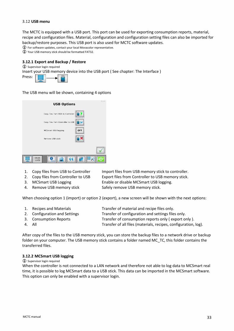
USB menu The MCTC is equipped with a USB port. This port can be used for exporting consumption reports, material, recipe and configuration files. Material, configuration and configuration setting files can also be imported for backup/restore purposes. This USB port is also used for MCTC software updates. For software updates, contact your local Movacolor representative.
Your USB memory stick should be formatted FAT32. 3.12.1 Export and Backup / Restore Supervisor login required
Insert your USB memory device into the USB port ( See chapter: The Interface ) Press: The USB menu will be shown, containing 4 options
1. Copy files from USB to Controller Import files from USB memory stick to controller. 2. 3.
Copy files from Controller to USB MCSmart USB Logging
Export files from Controller to USB memory stick. Enable or disable MCSmart USB logging.
4. Remove USB memory stick Safely remove USB memory stick. When choosing option 1 (import) or option 2 (export), a new screen will be shown with the next options:
1. Recipes and Materials Transfer of material and recipe files only. 2. Configuration and Settings Transfer of configuration and settings files only. 3. Consumption Reports Transfer of consumption reports only ( export only ). 4. All Transfer of all files (materials, recipes, configuration, log).
After copy of the files to the USB memory stick, you can store the backup files to a network drive or backup folder on your computer. The USB memory stick contains a folder named MC_TC, this folder contains the transferred files. 3.12.2 MCSmart USB logging Supervisor login required
When the controller is not connected to a LAN network and therefore not able to log data to MCSmart real time, it is possible to log MCSmart data to a USB stick. This data can be imported in the MCSmart software. This option can only be enabled with a supervisor login.

34 MCTC manual
3.12.3 Remove USB stick When you are ready with the required USB operations, it is mandatory to press the Remove USB memory stick button prior to unplugging the USB memory stick. You will be prompted when the synchronization has finished and it is safe to remove the USB memory stick. This synchronizes the files of your USB memory stick for safe removal.
Risk of damaging the data on your USB memory stick when it is not safely removed.
3.12.4 Insert USB memory stick When the Remove USB stick option is used, but the USB stick is not physically removed from the MCTC, it is possible to “insert” the USB stick again. In this way the USB stick does not have to be reinserted to be activated again. This might be useful when a MCTC is remotely controlled or when you forgot to copy files. The “Insert USB stick” function can be accessed by navigating to the USB menu again.
The controller detects if a USB stick is present in the USB port of the MCTC. If a USB stick is available, the screen aside appears. When the Insert USB stick button is pressed, the USB stick will be activated again.

35 MCTC manual
Consumption counters The MCTC is equipped consumption counters, counting the consumed material of each component. To reset the consumption counters you need at least TOOLING level login. 3.13.1 Consumption counter by order Consumption can be counted by order number. By changing the order number all consumption counters will be reset!
1. Order number Enter a production order number. Can be left blank, consumption will still be counted. Can be filled in afterwards.
2. Group total Total consumption for selected group (sum of all components).
3. Total Total consumption of the whole machine (sum of all groups).
4. Group selection Select the current group to be shown. Only visible when more than one group configured.
5. Component ID The ID and name of the components in the current selected group.
6. Material Material name of current loaded material file.
7. Consumption Current component consumption.
8. Reset Reset all consumption counters.
9. Export Report Generate a consumption report and export the last 5 to USB memory stick.
10. Exit Leave current screen.
1
4
5 6 7
2 3
8
9
10

36 MCTC manual
Consumption report A text formatted consumption report can be exported to a USB memory stick. This consumption report contains information about material usage per group and per component.
Each time an order number has been changed the consumption counters will be reset. At the same time a consumption report will generated and stored to the MCTC internal memory. The last 15 generated reports will be stored at the controller. See chapter USB menu for the data export function.

37 MCTC manual
4 Events
General In case of an error, the MCTC can generate events. When an error occurs using the MCTC, an event display
will pop up indicating the event type, code, source and description.
Together with the displayed event an output contact will be switched (Warning/Alarm output), this event
screen can be confirmed with the acknowledge button:
The controller itself gives a beeping signal and the red alarm LED will lighten up.
The MCTC keeps track of all active events (multiple simultaneous events are possible). Movacolor distinguishes 3 different events: Warning: Alarm/warning output is ON, but the system continues running and dosing. Soft Alarm*: Alarm/warning output is ON, the inline dosing units continue dosing, MCHybrid is in pause. Alarm: Alarm/warning output and the Alarm relay output are ON and the system stops running (no
dosing). * A soft Alarm is only applicable for a MCHybrid We distinguish 4 different event source levels: System: events like aux module events, production settings errors. Group: events like main material events. Unit: events like motor connection failures, load cell connection errors, CAN bus errors. Component: events like low hopper event, deviation errors.
Configuration (When working with multiple components, some configurations can be made on group level, other event configurations have to be made for each unit or component separately). For setting the free programmable events into Alarm Soft Alarm, Warning or off, enter the event configuration menu. The event configuration menu can be accessed in the advanced settings menu. By default the unit event configuration list is displayed Here you can select if the error will act as an alarm, soft alarm, warning or OFF. When OFF selected, no events will be displayed of this event.
1 Unit/Component navigation buttons
2 Event identifier
3 Event description
4 Event configuration
5 Event level selection buttons 2 3 4
5
1

38 MCTC manual
Active events
A list of all active events can be displayed by opening the event screen: An event is active as long the root cause of the event has not been solved. A message pop up of an active event will return every 60 seconds.
Operator events
Operator events can be shown by pressing: All (production) settings changed by the operator are recorded and can be reviewed in this list. A maximum of 50 events will be displayed in this list. More events are stored at the controller and can be downloaded by using MCSmart PC application or the USB function. Tooling login or higher required for recalling this list.
Alarm history
The warning/alarm event history list can be opened by pressing: A list with warning/alarms that occurred will appear. A maximum of 50 events will be displayed. More events are stored at the controller and can be downloaded by using MCSmart PC application or the USB function (csv file). The alarm history can be cleared using the reset button, only when logged in as supervisor. Tooling login or higher required for recalling this list.
Events 4.6.1 System events These events apply to the whole system.
Code Event Description Default
501 AUX module error! Cannot connect to AUX module Warning
502 Invalid MCSmart Address Range Wrong IP address for MCSmart server Warning*
503 No MCSmart communication Cannot connect to MCSmart server Warning*
1001 Write failed! Internal I2C write to memory failed Alarm*
1002 Production settings error Production parameters not set (correctly). Alarm
1501 Product weight deviation! LineControl output product weight is not within deviation limits od set product weight.
Warning*
1502 Maximum puller speed! LineControl maximum puller speed exceeded Warning*
4.6.2 Group events Group events can be set separately for each group in the system.
Code Event Description Default
2001 Main material empty! Main hopper is empty Off
2501 Extruder capacity deviation! LineControl Extruder capacity deviation between set and act capacity.
Warning*
2502 Minimum extruder speed! LineControl Extruder speed below minimum Warning*
2503 Maximum extruder speed! LineControl Maximum extruder speed exceeded Warning*

39 MCTC manual
4.6.3 Unit events Unit events can be set separately for each unit in a group.
Code Event Description Default
3001 Minimum motor speed! (<0.1 RPM) Required motor speed is too low Warning
3002 Max RPM Exceeded Required motor speed is too high Warning
3003 CAN bus connection failure CAN bus communication error Warning
3004 Motor connection failure! Short circuit detected!
Motor or cabling short circuit detected Warning
3005 Motor connection failure! Open connection detected!
Motor defect or not connected Warning
3007 Load cell connection failure! Load cell not connected or defective Alarm
3008 Door open! MCHybrid door open during production Softalarm
3009 Weigh bin not empty MCHybrid weigh bin not empty at production start Softalarm
3010 Weigh bin missing MCHybrid weigh bin not placed, or placed wrong Alarm
3011 Actual batch weight exceeds maximum batch weight!
More material is dosed in the weigh bin than allowed Warning
3012 Emergency button pressed! MCHybrid emergency button activated (Future use) Alarm
3013 Pause time exceeded! MCHybrid paused for more 10 minutes Alarm
3014 Low mixer MCHybrid200 mixer empty Warning
3015 Pellets not loaded Pellets are not sucked to disk Alarm
3016 Not calibrated MCNexus disk is not calibrated Alarm*
4.6.4 Component events Component events can be set separately for each component in a unit.
Code Event Description Default
4001 Empty level! Hopper level below empty level Warning
4002 Low level! Hopper level below low level Warning
4003 High high level! Hopper level above High High level (no RPM regulation)
Warning
4004 Maximum deviation exceeded! Deviation between set and act detected based on a rough weight measurements
Warning
4005 Maximum deviation exceeded! Deviation between set and act consistently bigger than deviation alarm setting [default: 25%] based
Warning
4006 Maximum deviation exceeded! MCHybrid deviation between set and act detected Warning
4007 Suggested correction to high! Suggested RPM correction too big, wrong dosing tool, material rat-holing or hopper empty
Off
4008 Total correction to high RPM correction too big, wrong dosing tool! Off
4009 Filling system unable to load material!
Fill system cannot complete filling within the set time period
Warning
4010 Slide not closed! Optional slide not closed Warning
4011 Calculated dosing weight too small, component skipped!
MCHybrid component dosing too small, component skipped for this batch
Warning
4012 Material flow error! Hopper empty?
MCHybrid component hopper material flow detected, hopper (almost) empty?
Warning
4013 Minimum valve capacity reached! Check valve configuration.
MCHybrid component skipped continuously, wrong dosing valve mounted?
Warning
4014 Hopper Missing Hopper is removed from unit Alarm
4015 Pellets Deviated MCNexus deviation between set and act detected. Off
4016 Pellets Missing MCNexus is missing pellets during dosing cycle. Warning
4017 Filling limiting measurement time! Time between filling cycles too short, system cannot measure accurately.
Warning
* This event cannot be configured.

40 MCTC manual
5 System
Main Material Sensor The MCTC or MCBC can be provided with a Main Material Sensor. This sensor can be used to detect a low material level in the main hopper. 5.1.1 Alarm settings When a Main Material Sensor is used, the alarm (event 2001) for this sensor needs to be set. Standard, the event is configured “OFF”. (Refer to chapter “Events” about how to setup events)
5.1.2 Electrical connections The main material sensor has 4 wires: brown, blue, white and black. The black wire should not be connected. The sensor needs to be connected to input 1 of the MCTC.
MCTC Terminal Wire color
12 Blue
13 White
14 Brown

41 MCTC manual
6 Batch mode In batch mode, the system doses a predefined batch when a start input is supplied. When dosing is ready, the MCTC gives a dosing ready signal.
Batch mode component configuration Each component in the batch setup can be configured separately. When the unloading option is required, this should be set in component 1 of the system. When the “BATCH” button of Figure 1 is pressed, the screen of Figure 2 appears.
Figure 1 Component Configuration screen

42 MCTC manual
6.1.1 Batch Settings For each batch dosing, the settings in the screen below can be made, except for the Batch unloading settings (5 and 6). These settings can only be set for component 1 in the system.
Figure 2 Batch Settings screen
1. Fine dosing set: this setpoint determines when the dosing unit switches from coarse to fine dosing speed.
2. Change delay: the time in which the motor speeds changes from coarse to fine dosing speed
3. Motor Speed Coarse: RPM when batch dosing is started
4. Motor Speed Fine: RPM setting for fine dosing.
Only component 1:
5. Unloading enabled: Enables or disables the unloading option
6. Unloading delay: Time before unloading output is activated
Example: Batch weight: 100 g, Batch settings as in Figure 2 When the MCTC gets a start input, the dosing unit will start dosing at 100RPM, when the last 10g (Fine Dosing Set) is reached, the RPMs are changed from 100 to 25 in a time of 2 seconds. The dosing unit will continue dosing at 25RPM until the total batch weight of 100 g is reached. 6.1.2 Batch unloading In some systems the batch needs to be unloaded from a buffer. This can be done with the Batch unloading option. When the option Batch unloading is enabled (5), potential free output 3 of the MCTC will close when batch dosing is ready. Now the batch can be unloaded by closing input 1 of the MCTC. When this input is activated, output 1 of the MCTC closes after the unloading delay time (6). This output can for example be used to control a valve.
1
2
3
4
5 6

43 MCTC manual
Batch mode production screen
Figure 3 Batch mode production screen
1. Total batch weight
2. Time unloading output is activated (only available when unloading option is enabled)
3. Set point unit 1, percentage of the total batch weight
4. Set point unit 2, percentage of the total batch weight
5. Toggle button. With this button you can toggle between the normal and the detailed view.
1
3 2 4
5

44 MCTC manual
Connection examples batch unloading 6.3.1 Example 1 – Batch with unloading controlled manually In this example, the start input and the unloading input are both controlled manually. When the Start dosing button is pushed, the system starts dosing. When dosing is ready, a light turns on and unloading can be activated by pushing the unloading button.
6.3.2 Example 2 – Batch with unloading controlled by MCTC In this example, the systems starts dosing when an external start input is given. When a batch is ready, output 1 will activate input 1 and the batch is unloaded after the loading delay time.

45 MCTC manual
6.3.3 Example 3 – Batch with unloading option activated by pushbutton In this example the system starts dosing when the start button is pressed. The start input is controlled by an external relay. This relay will interrupt the start input when the unloading valve is activated. When unloading is finished, the relay will give a new start input to the system for the next batch. No external start input is used.

46 MCTC manual
7 MCTwin
Introduction MCTwin is a software configuration of a double station MCBalance. One of the two units is adding regrind to the process, the other unit is adding the master batch (color) to the process. There are two available control modes for the MCTwin software, closed loop and open loop. In closed loop mode, the regrind is fed directly from the grinder to the dosing system, the dosed amount of colorant is automatically adjusted to the availability of regrind. In open loop mode, the regrind fed to the dosing system from a big regrind storage tank, assuming there is more than enough regrind available.
Closed loop regrind
4
3
2
1
0
Regrind Color
Grinder
Neckpiece
Virgin
Inj. Molding machine
Closed loop
4
3
2
1
0
Regrind Color
Neckpiece
Virgin
Inj. Molding machine
Open loop
47 MCTC manual
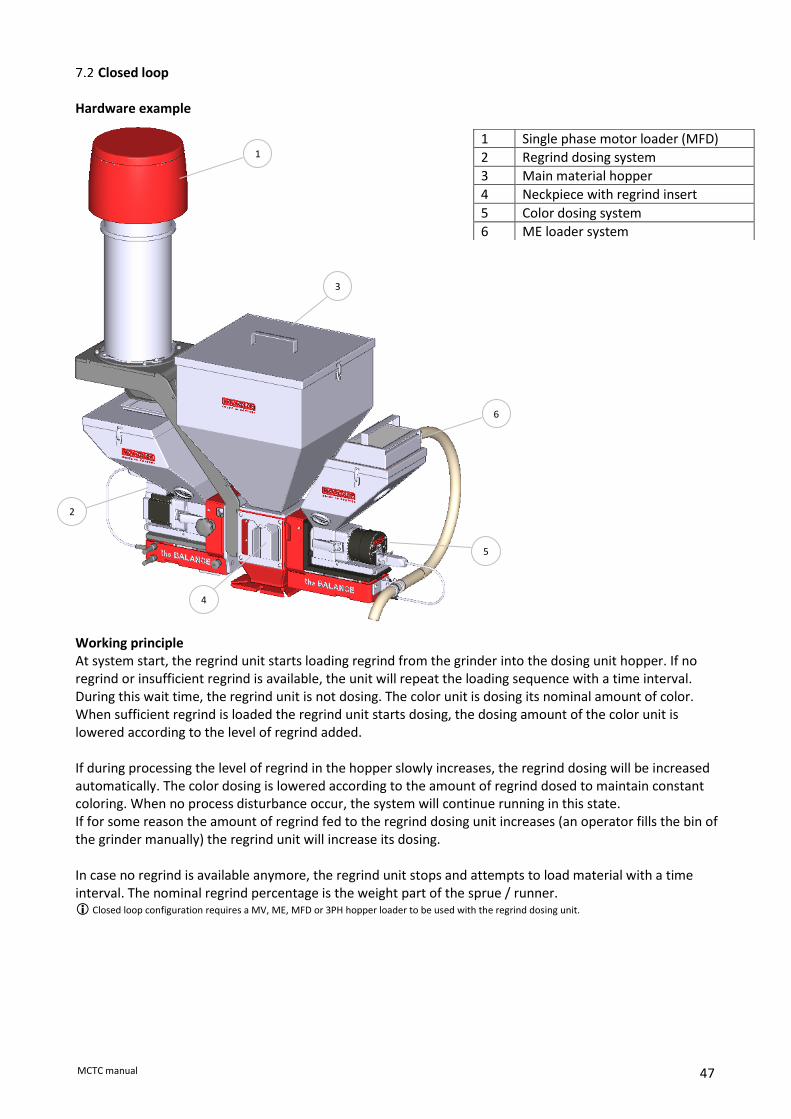
Closed loop Hardware example
Working principle At system start, the regrind unit starts loading regrind from the grinder into the dosing unit hopper. If no regrind or insufficient regrind is available, the unit will repeat the loading sequence with a time interval. During this wait time, the regrind unit is not dosing. The color unit is dosing its nominal amount of color. When sufficient regrind is loaded the regrind unit starts dosing, the dosing amount of the color unit is lowered according to the level of regrind added. If during processing the level of regrind in the hopper slowly increases, the regrind dosing will be increased automatically. The color dosing is lowered according to the amount of regrind dosed to maintain constant coloring. When no process disturbance occur, the system will continue running in this state. If for some reason the amount of regrind fed to the regrind dosing unit increases (an operator fills the bin of the grinder manually) the regrind unit will increase its dosing. In case no regrind is available anymore, the regrind unit stops and attempts to load material with a time interval. The nominal regrind percentage is the weight part of the sprue / runner. Closed loop configuration requires a MV, ME, MFD or 3PH hopper loader to be used with the regrind dosing unit.
1 Single phase motor loader (MFD)
2 Regrind dosing system
3 Main material hopper
4 Neckpiece with regrind insert
5 Color dosing system
6 ME loader system
1
2
3
4
5
6

48 MCTC manual
7.2.1 Configuration The MCTC needs to be configured as double station, see chapter 6 for more information about multicomponent configuration. MCTwin functionality is not available when a MCWeight is configured in the system MCBalance settings: See chapter MCBalance component configuration for more detailed MCBalance configuration. Enabling the MCTwin software operation, the material function has to be set to Regrind (R) using the recipe editor. From the horizontal menu bar, press the recipe button. Select material function “Regrind” (1) and press the save button. Next configure the regrind parameters via the “Regrind Configuration menu” Regrind component configuration:
Be sure the right component is selected by using the button.
1. Max fill level
2. Fill level for Nominal regrind dosing
3. Maximum time used for one fill sequence
4. Time between fill retry, when no regrind is available.
5. % of additional regrind when hopper level is above Regrind level
6. Manual fill
7. Advanced loader settings
2
3
4
5
6
1
7
1

49 MCTC manual
High level [default 4000gr]: When hopper level above this level the unit will freeze its motor speed because inaccurate weight measurement. The regrind unit will dose extra regrind. As soon the hopper weight is below this level the unit returns to normal gravimetric operation. This level is related to the maximum volume of the regrind dosing unit hopper [~10 liters]. Method 1: Regrind bulk density: 700 gr/liter. High level: 700x10 = 7000gr.
Method 2: Take the hopper from the machine and fill manually with material until the mark shown in picture below and put back the hopper on the machine. Read out the weight on the MCTC .
Regrind level [default 3500gr]:
The weight used to calculate all internal fill start levels and regrind dosing rate levels. This setting depends on the size of the storage hopper of the grinder. Method 1: Grinder hopper volume: 5 liter.
Regrind bulk density: 700 gr/liter. Regrind level: 5 x 700 = 3500gr.
Method 2: Set Regrind level 500 grams below High level.
Fill time [default 30sec]: Maximum time the unit tries to load material from the grinder. In case a ME or EX loader system is configured, this is the maximum time the loader is activated or the knife gate of the support frame is opened. In case of a MFD loader, this time setting should not be set longer than the MFD Fill time + MFD Empty time + MFD blow back time (see advanced loader settings) In case of a 3PH loader, this time setting should not be set longer than the 3PH Fill sequence time set on the 3PH loader controller (see 3PH loader manual for detailed information).
Fill interval time [default 180sec]: Time between two attempts to load material from the grinder when the dosing hopper is empty eg. regrind unit standby.
Extra regrind [default 5%]: When more regrind is available, the dosing percentage of the regrind unit is increased with this %.
Example:
• Regrind percentage in production settings: 20% (nominal);
• Extra regrind: 5%;
• Regrind level: 3500gr;
• Hopper level after a fill sequence: 3750gr;

50 MCTC manual
• This results in a regrind dosing set point: 20% +5% = 25%. 7.2.2 Production The regrind percentage setting can be calculated as follows: (Sprue weight / shot weight) * 100 = Regrind percentage. Injection Molding – closed loop regrind - gravimetric mode
Production settings: The following parameters can be seen in the production screen, depending on operation or settings: The production data can be entered by touching the corresponding field
1. Material Movacolor pre-programmed curve (dosing tool/granule type), or USER defined curve (material name) is displayed. (not available when recipe function is activated)
2. Nominal regrind amount (%) 3. Recalculated regrind amount (%) 4. Shot weight (gr.) 5. Dosing set time (sec.) Dosing set time only visible in Timer mode, otherwise relay time will be displayed
6. Nominal color amount (%) 7. Recalculated color amount (%), reduced by regrind amount 8. Prime. Filling the dosing cylinder before start.
The prime menu appears by pressing . Settings (speed/time) can be changed. Press confirm to start priming.
9. Production (Motor On/Off) Press to start dosing. The motor on/off switch will turn from green to red when dosing is started. The start LED blinks when the unit is waiting for an input signal. If the unit is dosing the Start LED lights continuously. For stopping production press again. The motor on/off switch will turn to green again.
Please note that it is possible that the first dosing(s) are not sufficient, because of the cylinder filling with material. It takes some time to stabilize.
4 1
2
1
5 6
8 9
3 7

51 MCTC manual
Injection molding – closed loop - gravimetric mode Actual production data: Using the toggle button , you can switch between production settings and production data.
1. Set and actual output: Set.: Re-calculated output (% kg/h, gr/sec). Act.: Actual additive output (% kg/h, gr/sec). actual additive output is only visible after the first automatic RPM adjustment.
2. Speed: Actual motor speed (RPM). 3. Hopper weight: Material weight in the hopper. 4. Time: Set dosing time (sec), when working TIMER input mode.
The average dosing time (sec), when working in RELAY input mode. 5. Act. Time: Count down of the actual dosing time (sec).
1 1 4
5
2 2
3 3

52 MCTC manual
Open Loop Working principle In open loop configuration the amount of dosing of the color unit is adjusted to the level of regrind dosed by the regrind unit, regrind is fed to the system by either a ME, EX, MFD or 3PH hopper loader or knife gate when using a MCHigh Output. If at system start no regrind is available (hopper weight below EMPTY level), the regrind unit will not start dosing. The color unit will dose it’s nominal %. To start the regrind unit, manual activation of the loader system is required. The loading system will now. Be able to start while the system is switched off! When during production no regrind is available, the unit will give an alarm. As soon as the regrind material hopper is below EMPTY level, the regrind unit will stop dosing. The color unit dosing amount will increase to nominal to maintain color level. To restart the regrind dosing, the manual activation of the loader system is required.

53 MCTC manual
7.3.1 Production The regrind percentage setting can be calculated as follows: (Sprue weight / shot weight) * 100 = Regrind percentage. Injection molding - open loop regrind - gravimetric mode
Production settings: The following parameters can be seen in the production screen, depending on operation or settings: The production data can be entered by touching the corresponding field
1. Material: Movacolor pre-programmed material (dosing tool/granule type), or USER defined material is displayed (not available when recipe function is activated).
2. Nominal regrind amount (%) 3. Recalculated regrind amount (%) 4. Shot weight (gr.) 5. Dosing set time (sec.) Dosing set time only visible in Timer mode, otherwise relay time will be displayed
6. Nominal color amount (%) 7. Recalculated color amount (%), reduced by regrind amount 8. Prime. Filling the dosing cylinder before start.
The prime menu appears by pressing . Settings (speed/time) can be changed. Press confirm to start priming.
9. Production (Motor On/Off) Press to start dosing. The motor on/off switch will turn from green to red when dosing is started. The start LED blinks when the unit is waiting for an input signal. If the unit is dosing the Start LED lights continuously. For stopping production press again. The motor on/off switch will turn to green again.
Please note that it is possible that the first dosing(s) are not sufficient, because of the cylinder filling with material. It takes some time to stabilize.
4 1
2
1
5 6
8 9
3 7

54 MCTC manual
Injection molding – open loop - gravimetric mode Actual production data: Using the toggle button , you can switch between production settings and production data.
1. Set and actual output: Set.: Re-calculated output (% kg/h, gr/sec)
Act.: Actual additive output ((%, gr/s or kg/h) actual additive output is only visible after the first automatic RPM adjustment.
2. Speed: Actual motor speed (RPM) 3. Hopper weight: Material weight in the hopper
4. Time: Set dosing time (sec), when working TIMER input mode. The average dosing time (sec), when working in RELAY input mode.
5. Act. Time: Count down of the actual dosing time (sec)
1 1 4
5
2 2
3 3

55 MCTC manual
8 Multi component
MCTC multi component controller
The Movacolor touchscreen controller and modular design of the Movacolor components offers you an enormous flexibility in combining your dosing/measuring devices. With this system it is possible to connect up to 15 different devices to one neckpiece and directly to your injection molding machine or extruder With the MCTC it is possible to control and monitor the mixing ratio of these different components from one screen. The group functionality enables you control and monitor the feeding of additives in co-extrusion co-injection setups from one touchscreen. Each group with its one start/tacho input signal and production parameters. Up to 15 groups can be configured easily.
4 component system example
Component Type Material example
1 MCWeight 1200. Main virgin material.
2 MCHigh Output G-500. Regrind.
3 MCBalance with ME25 loading system. Color additive.
4 MCBalance with SFG Support frame for external hopper loader. Foaming additive.
1
2
3
4

56 MCTC manual
Group structure With the group structure it is possible to control/monitor the dosing systems of different co-injection molding or co-extrusion separately from one touchscreen controller.
3 group co-extrusion example
In this example co-extrusion of 3 extruders, each with a MCWeight 500 and one MCBalance. All controlled from one MCTC. This example is used in the next paragraph. The units are equipped with MC Blind Controllers (2 MCBC’s per extruder, 6 in total) Software Group navigation
Extr. A
Extr. B Extr. C

57 MCTC manual
Group configuration Go to the advanced configuration menu:
• Set the number of groups to 3;
• Configure the groups by clicking the group configuration button: The Group configuration menu is shown. Here you can enter the number of units for each group, change the name of the group and select the type of devices used in the current selected group. Note: When a MCNexus is used in a group, no other components than the MCNexus can be configured for this group. The dipswitch setting of the blind controllers should correspond with the addresses shown in this window (See: Component controller addressing)
MCBC blind controller
For a multicomponent setup you need at least one MCTC touchscreen controller and one MCBC blind controller. For each additional unit you need an additional blind controller. This blind controller is a control box without display and touchscreen, and is used to connect to the unit load cell, stepper motor, valves and sensors. The MCTC is used as main controller and uses a CAN bus to communicate to the blind controllers.
For group configurations, the first controller in each group needs input signals from the (co)extruder / IMM. WARNING: make sure the input signals of different units are not connected to each other. This might cause damage to the controller.
1 Group navigation buttons.
2 Group name.
3 Unit identifier.
4 CAN bus address (dipswitch setting).
5 Unit type.
6 Unit name.
7 Number of units in selected group.
INPUT SIGNAL GROUP A INPUT SIGNAL GROUP B
GROUP A GROUP B
2
1 1
7
3
4
5
6

58 MCTC manual
CAN bus connection The MCTC and MCBC units communicate using a CAN BUS connection. When you order a multicomponent system at Movacolor it will be delivered pre-wired with the correct cabling. In case you need to make adjustments in the cabling, be aware to connect the CAN bus correctly. There can only be one MCTC touchscreen connected to the cable loop.
Always use Movacolor selected CAN bus cable, use of wrong cabling can result in a defective system.
Alarm/warning output In a multicomponent configuration, all alarms are centralized to the first unit (MCTC UNIT 1). In case of an alarm on a blind controller unit X, the alarm output of unit 1 and the alarm output of unit X are activated.
Number Wire color Function
3 Cable shield Shielding
4 Blue CAN Low
5 White CAN High
From previous unit
To next unit
Alarm light/sounder Optional alarm light/sounder

59 MCTC manual
Unit controller addressing Each of the controllers is given a number/address. This is set with the internal dipswitches on the mainboard of the controller. To get access to the dipswitch, untighten the 4 hexagon screws on the side of the controller cabinet (do not completely remove the screw). Now you’re able to slide open the cabinet and access the dipswitches. Addressing is according to the next table
Switch 5 and 6 should always be in the OFF position. Switches 7 and 8 are used for CAN bus termination according to the CAN bus specification. These needs to be switched ON at the last unit of the connected string. Example: A system with 5 units: Unit 1 Unit 2 Unit 3 Unit 4 Unit 5 During operation each blind controller needs to be powered on. Even if the unit is not used (dosing percentage at 0%) The multi-component setup needs only one input cable to supply the start and/or tacho signal to the system. This input cable needs to be connected to Unit 1 In a multi-group setup each first unit in a group needs an input cable to supply start and/or tacho signal.
Unit Address Switch setting
1 2 3 4
Unit 1 0 OFF OFF OFF OFF
Unit 2 1 ON OFF OFF OFF
Unit 3 2 OFF ON OFF OFF
Unit 4 3 ON ON OFF OFF
Unit 5 4 OFF OFF ON OFF
Unit 6 5 ON OFF ON OFF
Unit 7 6 OFF ON ON OFF
Unit 8 7 ON ON ON OFF
Unit 9 8 OFF OFF OFF ON
Unit 10 9 ON OFF OFF ON
Unit 11 10 OFF ON OFF ON
Unit 12 11 ON ON OFF ON
Unit 13 12 OFF OFF ON ON
Unit 14 13 ON OFF ON ON
Unit 15 14 OFF ON ON ON
Unit 16 15 ON ON ON ON

60 MCTC manual
MCTC remote setup Movacolor recommends keeping the motor and load cell cables as short as possible to avoid interference which could cause an inaccurate measurement system. Therefore it is possible to place the MCTC touchscreen at a different place in your factory. This also useful when your machine (and touchscreen panel) is difficult to reach. You can order at Movacolor a special modification kit to convert your MCTC controller into a “remote” version. Ask your Movacolor representative for detailed information. MCTC Terminal MCBC
Cable connection scheme:
MCTC TERMINAL MCBC MAINBOARD
P Name Color P Name Color
1 Shield Shield 1 GND Black
2 GND Black 2 +24VDC Red
3 +24VDC Red 3 Shield Shield
4 CAN-L Blue 4 CAN-L Blue
5 CAN-H White 5 CAN-H White

61 MCTC manual
Multi component production 8.8.1 Injection molding - gravimetric mode Production settings: The following parameters can be seen in the production screen, depending on operation or settings: The production data can be entered by touching the corresponding field
1. Unit button To enter unit screen. Detailed production settings and parameters can be set and read
2. Additive amount (%) 3. Production status 4. Total shot weight (gr.) 5. Dosing set time (sec.) Dosing set time only visible in Timer mode, otherwise relay time will be displayed
6. Recipe menu
7. Prime. Filling the dosing cylinder before start. The prime menu appears by pressing . Settings (speed/time) can be changed. Press confirm to start priming. Each unit must be primed separately, select the unit to prime before pressing the prime button.
8. Production (Motor On/Off) Press to start dosing. The motor on/off switch will turn from green to red when dosing is started. The start LED blinks when the units are waiting for an input signal. If the units are dosing the Start LED lights continuously. For stopping production press again. The motor on/off switch will turn to green again.
Please note that it is possible that the first dosing(s) are not sufficient, because of the cylinder filling with material. It takes some time to stabilize.
1
2
3
4 5
6 7 8

62 MCTC manual
8.8.2 Extrusion - gravimetric mode - tacho
Production settings: The following parameters can be seen in the production screen, depending on operation or settings: The production data can be entered by touching the corresponding field .
1. Unit button To enter unit screen. Detailed production settings and parameters can be set and read
2. Additive amount set point (%) (dosing % can be set from this screen) 3. Production status 4. Actual extruder throughput (kg/h.) Only visible in tacho mode or with MCWeight. 5. Actual tacho voltage Only visible in tacho mode.
6. Recipe menu
7. Prime. Filling the dosing cylinder before start. The prime menu appears by pressing . Settings (speed/time) can be changed. Press confirm to start priming. Each unit must be primed separately, select the unit to prime before pressing the prime button.
8. Production (Motor On/Off) Press to start dosing. The motor on/off switch will turn from green to red when dosing is started. The start LED blinks when the units are waiting for an input signal. If the units are dosing the start LED lights continuously. For stopping production press again. The motor on/off switch will turn to green again.
Please note that it is possible that the first dosing(s) are not sufficient, because of the cylinder filling with material. It takes some time to stabilize.
4
6
5
7
2
1
3
8

63 MCTC manual
8.8.3 Extrusion - gravimetric mode - relay Production settings: The following parameters can be seen in the production screen, depending on operation or settings: The production data can be entered by touching the corresponding field
1. Unit button: To enter unit screen. Detailed production settings and parameters can be set and read 2. Additive amount set point (%) (dosing % can be set from this screen) 3. Production status 4. Extruder throughput set point(kg/h.) 5. Recipe menu
6. Prime: Filling the dosing cylinder before start. The prime menu appears by pressing . Settings (speed/time) can be changed. Press confirm to start priming. Each unit must be primed separately, select the unit to prime before pressing the prime button.
7. Production (Motor On/Off) Press to start dosing. The motor on/off switch will turn from green to red when dosing is started. The start LED blinks when the units are waiting for an input signal. If the units are dosing the start LED lights continuously. For stopping production press again. The motor on/off switch will turn to green again.
Please note that it is possible that the first dosing(s) are not sufficient, because of the cylinder filling with material. It takes some time to stabilize.
4
5 6
2
1
3
7

64 MCTC manual
9 Outputs
MCBalance, MCPowder, MCHigh Output, MCLiquid For the location of the output connections, see Electrical connections Alarm / Warning Output Connection 27 and 28. Warning event: this output is on (24V), the system continues running). Alarm event: this output is on (24V), the system stops running. Free programmable events can be programmed to an Alarm or Warning. See chapter: Events. For alarm light connection in multicomponent systems see paragraph: Alarm/warning output in the Multicomponent sector. Valve Output Connection 29 and 30. This output is on (24V) to start the hopper loader or open the knife gate. Alarm Output (OUT-1) Normally open contact, connection 32 and 33. Normally closed contact, connection 32 and 34. Alarm event: this output is activated, the systems stops running. Run Output (OUT-2) Normally open contact, connection 35 and 36. The “RUN signal” can be used as a Start/Stop condition for the molding machine. For example: Molding machine can only start in case dosing unit is also started. Default the Run output 2 (OUT-2) is always on in production mode (status Dosing or Standby) Production status = STANDBY or DOSING → output 35 and 36 is CLOSED. Production status = OFF → output 35 and 36 is OPEN. In case of alarm, the alarm output (OUT-1) is switched and the system is stopped. This also switches output OUT-2.
AUX Output (OUT-3) Normally open contact, connection 41 and 42. Function of OUT-3 depends on loader configuration.
Loader Function Action
ME No action No Action
MV No action (can be used for 3rd party loader) 41 – 42 output CLOSED during fill time
EX No action No Action
3PH Activation of blower loading sequence 41 – 42 output CLOSED during filling
MFD Activation of compressed air filter cleaning 41 – 42 output CLOSED during blowback time

65 MCTC manual
MCHybrid For the location of the output connections, see Electrical connections Mixer valve (OUT-10) Connection 25 and 26. In case a MCHybrid is used OFFLINE, on top of a storage bin. It is required to use a material valve underneath the MCHybrid to guarantee a right mixture. This valve can be connected to this output. See MCHybrid configuration for enabling this function. Mixer full and mixing finished: this output is on (24V). Alarm / Warning Output (OUT-13): Connection 29 and 30. Warning event: this output is on (24V), the system continues running. Soft Alarm event: this output is on (24V), the MCHybrid system is in PAUSE. Alarm event: this output is on (24V), the system stops running. Free programmable events can be programmed to an Alarm, SoftAlarm or Warning. See chapter: Events - Configuration for configuring events. For alarm light connection in multicomponent systems see chapter: Multicomponent – Alarm/warning output. Alarm Output (OUT-13) Normally open contact, connection 34 and 35 Alarm event: this output is activated, the systems stops running. Run Output (OUT-14) Normally open contact, connection 36 and 37 The “RUN signal” can be used as a Start/Stop condition for the molding machine. For example: Molding machine can only start in case dosing unit is also started. Default the Run output 2 (OUT-2) is always on in production mode (status Running or Ready) Production status = STANDBY or DOSING → output 36 and 37 are CLOSED. Production status = OFF → output 36 and 37 are OPEN. In case of alarm, the alarm output (OUT-13) is switched (on) and the system is stopped. This also switches output OUT-14 (off).

66 MCTC manual
10 Trouble shooting Problem: The dosing system does not come into specification or a Maximum deviation alarm occurred. Possible causes: 1. Check if all cables are connected correctly. 2. Check if the hopper assembly is fixed tightly to the weighing platform and that the neckpiece is fixed
tightly to the production machine. 3. Check if the dosing tool is tightly fixed to the motor shaft. 4. Excessive build-up of material on the dosing tool may have impact on proper dosing. To avoid this, be sure that the seals and dosing cylinder are clean. 5. Check if there is no tension on the cables connected to the weighing platform. 6. Use the weight check function with the reference weight to determine the correct function of the
weighing system. 7. If the weight check gives the correct result, check if the material flow into the dosing tool has been
blocked.
8. Another cause may be an obstruction to the weighing system. Check if there is at least 1mm space between all the pointed safety screws and the load cell frame or platform and that there is no material or dirt blocking the movement.
9. In case of a water cooled neckpiece, check if there is material build up around the dosing cylinder and the water cooled pipe that can obstruct the free movement of the weighing system.
10. Check if the input signal is stable. 11. If none of the above causes the problem, recalibrate the system and try the weight check again. Problem: The dosing system does come into specification but seems to be slow. Possible causes: 1. Extreme vibrations and shocks to the system. 2. Extreme low Set point. See chapter: System performance. 3. Check in case of use of an automatic hopper loader if the hoses are connected in the right way. Problem: The input/start-signal is connected but the unit does not recognize this start signal. Possible causes: 1. Check if the correct wires are connected for potential free contact, potential contact or tacho. Also check
if the + and – side are connected correctly. 2. Automatic fuse is activated, this can for example happen when there was a short-circuit at the input
connection. To deactivate the automatic fuse the controller needs to be switched OFF for a while and ON again, but first check and repair the short-circuit.
Problem: The hopper weight is not stable. Possible causes: 1. Check if the weighing signal is not influenced by external circumstances, for example that the load cell
cable passes near to electromagnetic fields or electro motors. 2. Extreme vibrations and shocks to the system. 3. Check if there is no obstruction to the weighing frame. 4. Check in case of use of an automatic hopper loader if the hoses are connected in the right way. Problem: USB copy function does not work properly. Possible causes: 1. Some brands of USB memory sticks are not correctly detected by the MCTC. Please try another brand of
USB memory stick. 2. The USB memory stick is not properly formatted, be sure the USB memory stick is formatted FAT32. 3. If the USB menu can be opened without USB memory stick, please press “Remove USB stick” and insert
USB memory stick again.

67 MCTC manual
APPENDIX A: MCTC Technical Specifications Controls: Input: Set and actual % setting for injection molding and extrusion Extrusion control: By relay or tacho Injection molding control: Automatic metering time synchronization or by manual timer Manual speed and time setting Speed: Manual setting from 0,1 to 200 RPM max, in increments of 0,1 RPM.
Time: Manual settings from 0,1 to 999 sec in increments of 0,1 sec. Security: 3 user levels with automatic logout Loader system: Integrated hopper loader controller Recipes: Up to 1000 materials and up to 1000 recipes can be stored. Monitoring/System Information/External communication External Communication: PC link using TCP/IP internet protocol Modbus TCP/IP Optional: Profibus DP slave, Profinet slave, Analog output Alarm: 2 user alarm levels Specifications/Standards & Directives/ Technical data: Power supply: Operating power from 95 VAC to 250 VAC, 50 and 60 Hz by integrated automatic voltage selector Power consumption: 150 Watt maximum Stepper motor: (1,8degr/step) max 2A or 4A(high output) at 48 Volt. Operating Temperature: -20 to +70 degrees Celsius. Load cell and electronics: 20 bits A/D resolution with a full digital filtering Battery: Used for date/time. Lifetime without mains power approx. 5 years. Type: CR2354 Input signal(s): Injection molding: Start/Stop trigger input, potential free or 24VDC* Extrusion: Start/Stop trigger input, potential free or 24VDC* Tacho input 0..30VDC * Note potential contact Guaranteed OFF: 0-8VDC Guaranteed ON: 18-30VDC Output(s):
• -Stepper motor max. output 2A or 4A(high torque) at 48VDC
• -Solid state 24VDC/0.5 A output for valve hopper loader*
• -Solid state 24VDC/0.5 A output for external warning*
• -Relay for alarm level (max. 230Vac/30Vdc, 5A)
• -Relay for running contact (max. 230Vac/30Vdc, 5A) * Maximum total output power: 12 Watt (Valve output + alarm output) Standard Directives: Protection class: IP-50 According to CE standards Safety In case of overload due to short-circuit or incorrect connection, the power supply automatically shuts down. Opto-insulated start input for connection to production machine. Optional parts External Alarm Flash light. External Alarm Siren. Profibus DP slave module Profinet module Analog output module MCBalance Machine connection flange: Standard flange NSt40-neckpiece with cleaning opening.
Inlet/outlet ø50mm/40mm, steel epoxy coated RAL 3002 Load frame:
• - Balance frame: Steel, epoxy coated RAL 3002
• - Weighing frame: Aluminum, epoxy coated RAL 9005
• - Load cell: Nominal Load: 20 or 50 kg. Temp. compensated Temp. range: -20…+60 gr. Celsius Protection level: IP63 EN60529

68 MCTC manual
APPENDIX B: MCTC Dimensional drawing
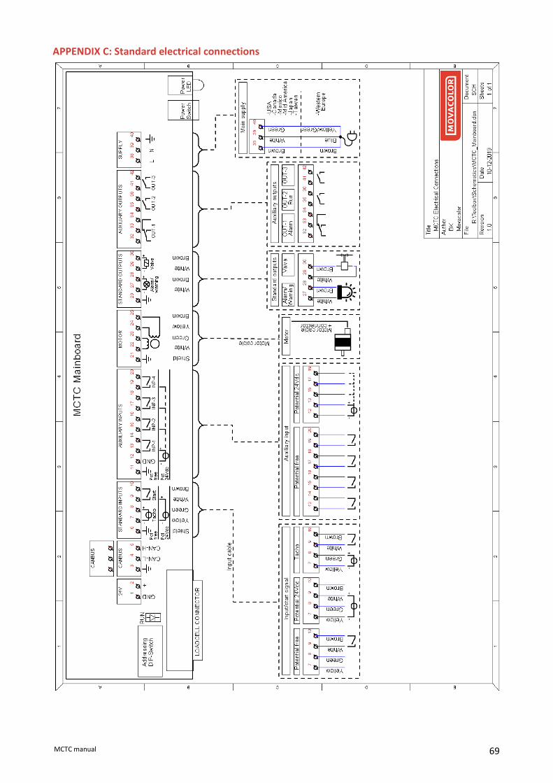
69 MCTC manual
APPENDIX C: Standard electrical connections

70 MCTC manual
APPENDIX D: Declaration of conformity
DECLARATION OF CONFORMITY
(According to 2006/42/EC)
Manufacturer’s name : MOVACOLOR BV
Address : P.O. Box 3016 8600 DA Sneek The Netherlands www.movacolor.com Declare under our sole responsibility that the product: Product description : Dosing equipment Product designation : MCTC, MCBC In combination with : MCBalance, MCHighOutput, MCWeight, MCLiquid, MCPowder, MCHybrid, MCNexus, MCNumera Year : 2021 Identification : From serial number 27500 onwards
- The object of the declaration described above is in conformity with the relevant Union harmonization legislation;
Machine Directive 2006/42/EC EMC Directive 2014/30/EU RoHS 2011/65/EU
- The following harmonized standards and technical specifications have been applied: EN 60204-1 Safety of machinery - Electrical equipment of machines. Part 1: General requirements EN 61010-1:2010 Safety requirements for electrical equipment for measurement, control, and laboratory use. Part 1: General requirements Name: Gerhard Dersjant Place: Sneek the Netherlands
Position: Managing Director Date: February 2021
Signature:

71 MCTC manual