me 113 computer aided engineering...
TRANSCRIPT
ME 113
Computer Aided Engineering
Drawing
Asst.Prof.Dr.Turgut AKYÜREK
Çankaya University, Ankara
Orthographic Projection - Visualizing Solids
and Multiview Drawings
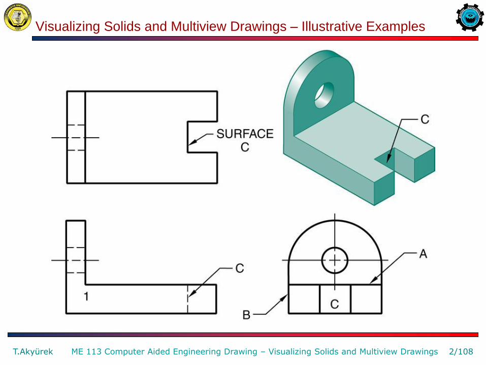
Visualizing Solids and Multiview Drawings – Illustrative Examples
T.Akyürek 2/108 ME 113 Computer Aided Engineering Drawing – Visualizing Solids and Multiview Drawings

Visualizing Solids and Multiview Drawings – Illustrative Examples
T.Akyürek 3/108 ME 113 Computer Aided Engineering Drawing – Visualizing Solids and Multiview Drawings
Visualizing Solids and Multiview Drawings – Illustrative Examples
T.Akyürek 4/108 ME 113 Computer Aided Engineering Drawing – Visualizing Solids and Multiview Drawings
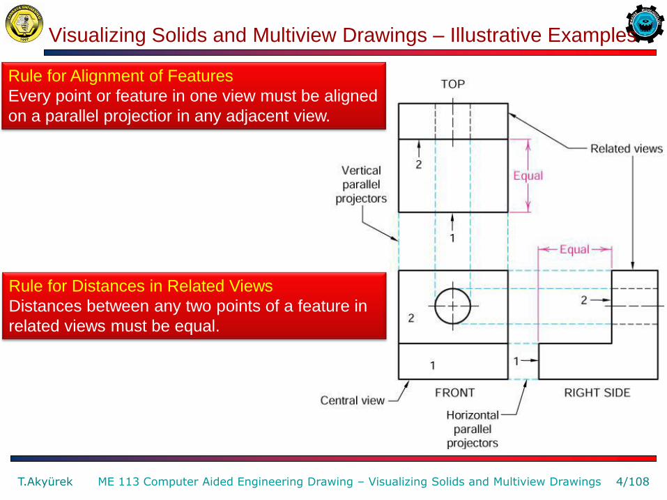
Rule for Alignment of Features
Every point or feature in one view must be aligned
on a parallel projectior in any adjacent view.
Rule for Distances in Related Views
Distances between any two points of a feature in
related views must be equal.

Fundamental Views of Edges for Visualization
T.Akyürek 5/108 ME 113 Computer Aided Engineering Drawing – Visualizing Solids and Multiview Drawings
Fundamental Views of Edges
Determine the fundamental views of edges on a multiview drawing by the position of the object relative to the current line of sight and the relationship of the object to the planes of the glass box.
Rule for True Length and Size
Features are true length or true
size when the lines of sight are
perpendicular to the feature.
Rule for Foreshortening
Features are foreshortened
when the lines of sight are not
perpendicular to the feature.

Fundamental Views of Edges for Visualization
T.Akyürek 6/108 ME 113 Computer Aided Engineering Drawing – Visualizing Solids and Multiview Drawings
Oblique Line
Oblique line 1-2 is not parallel to any of the principal planes of the projection of the glass box.

Fundamental Views of Principal Planes for Visualization
T.Akyürek 7/108 ME 113 Computer Aided Engineering Drawing – Visualizing Solids and Multiview Drawings
Normal Faces
Projection of the normal faces onto the image plane.
Fundamental Views of Principal Planes for Visualization
T.Akyürek 8/108 ME 113 Computer Aided Engineering Drawing – Visualizing Solids and Multiview Drawings
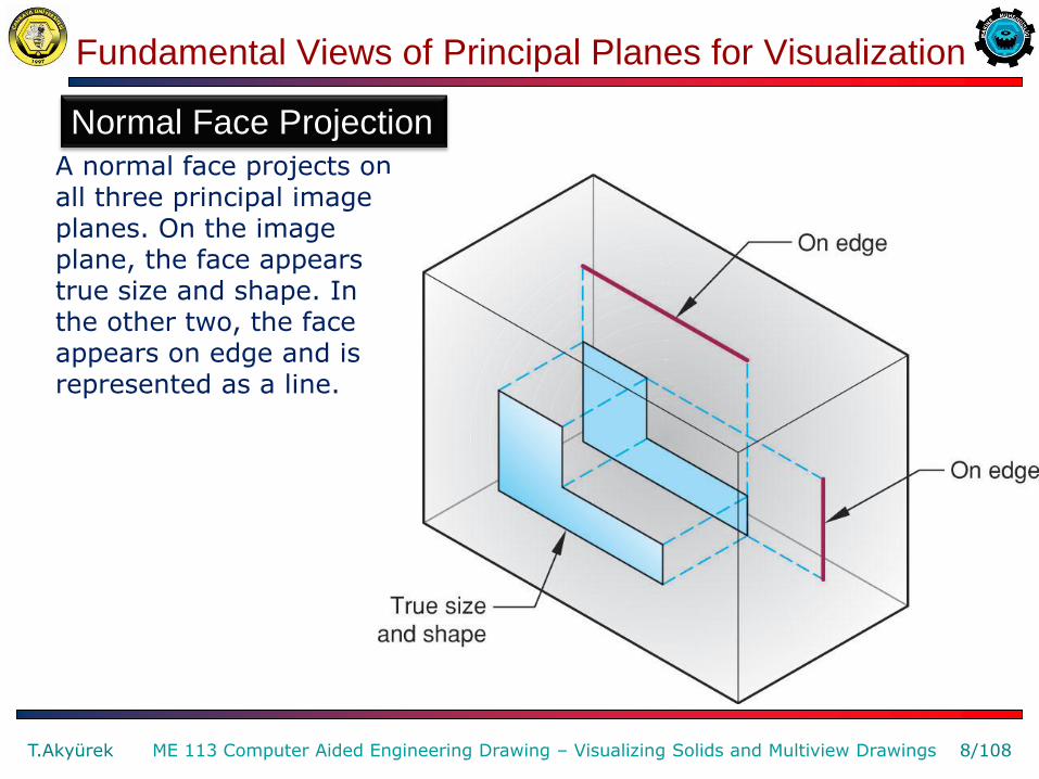
Normal Face Projection
A normal face projects on all three principal image planes. On the image plane, the face appears true size and shape. In the other two, the face appears on edge and is represented as a line.
Fundamental Views of Principal Planes for Visualization
T.Akyürek 9/108 ME 113 Computer Aided Engineering Drawing – Visualizing Solids and Multiview Drawings
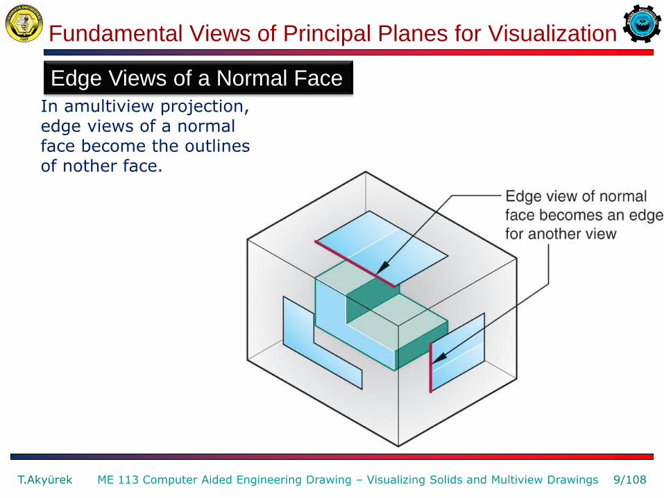
Edge Views of a Normal Face
In amultiview projection, edge views of a normal face become the outlines of nother face.
Fundamental Views of Principal Planes for Visualization
T.Akyürek 10/108 ME 113 Computer Aided Engineering Drawing – Visualizing Solids and Multiview Drawings
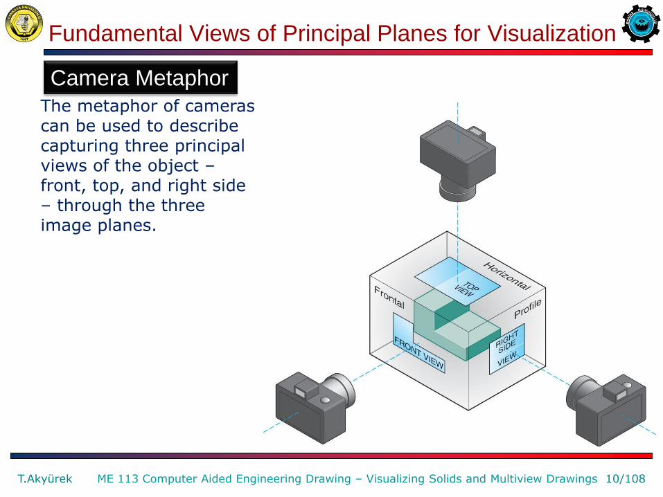
Camera Metaphor
The metaphor of cameras can be used to describe capturing three principal views of the object – front, top, and right side – through the three image planes.
Fundamental Views of Inclined Planes for Visualization
T.Akyürek 11/108 ME 113 Computer Aided Engineering Drawing – Visualizing Solids and Multiview Drawings
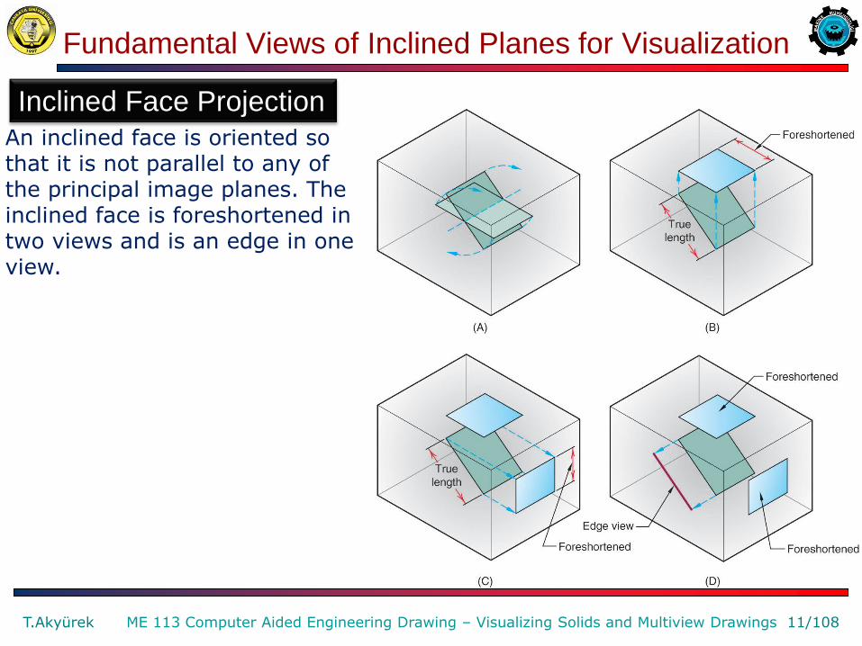
Inclined Face Projection
An inclined face is oriented so that it is not parallel to any of the principal image planes. The inclined face is foreshortened in two views and is an edge in one view.
Fundamental Views of Inclined Planes for Visualization
T.Akyürek 12/108 ME 113 Computer Aided Engineering Drawing – Visualizing Solids and Multiview Drawings
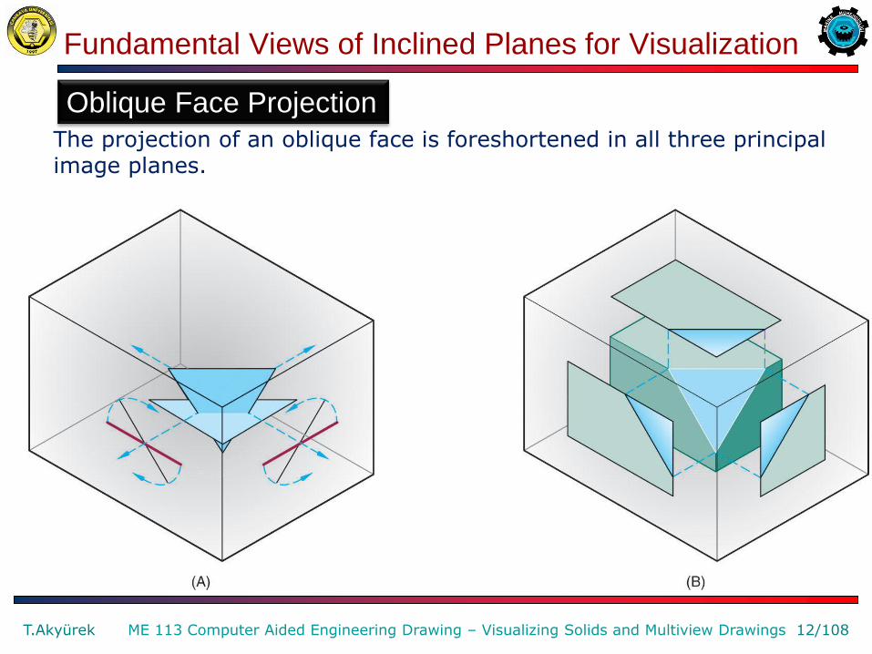
Oblique Face Projection
The projection of an oblique face is foreshortened in all three principal image planes.

Fundamental Views of Surfaces for Visualization
T.Akyürek 13/108 ME 113 Computer Aided Engineering Drawing – Visualizing Solids and Multiview Drawings
Fundamental Views of Surfaces
Surface A is parallel to the frontal plane of projection. Surface C is parallel to the profile plane of projection. Surface D is an inclined plane and is on edge in one of the principal views (the front view). Surface E is an oblique plane and is neither parallel nor on edge in any of the principal planes of projection.

Multiview Drawings of Solid Primitive Shapes
T.Akyürek 14/108 ME 113 Computer Aided Engineering Drawing – Visualizing Solids and Multiview Drawings
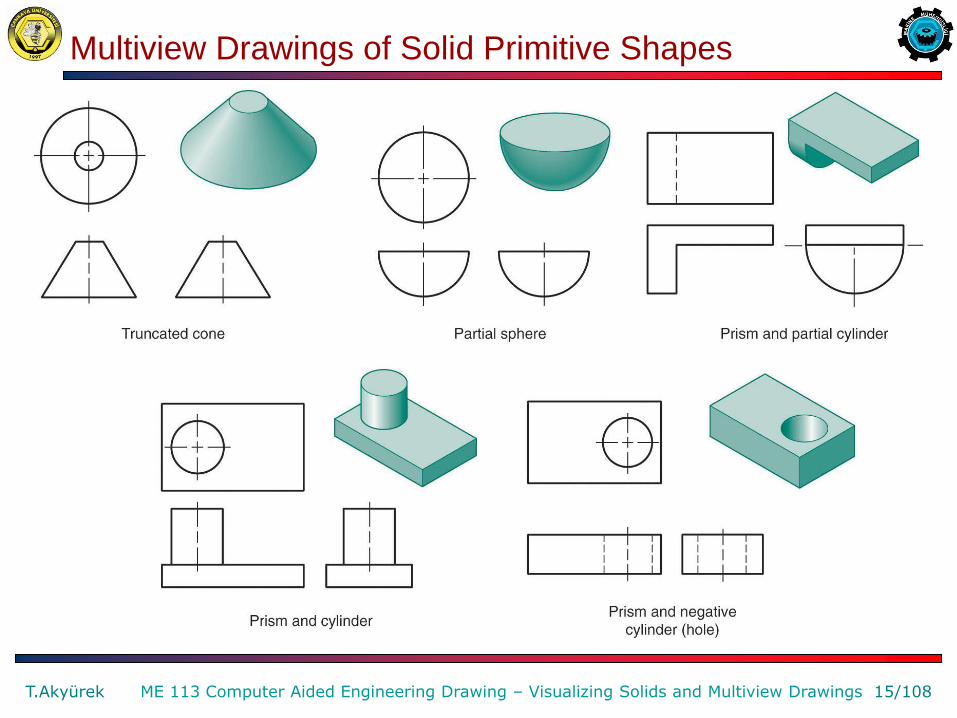
Understanding and recognizing these shapes will help you to understand their application in technical drawings. Notice that the cone, sphere, and cylinder are represented with fewer than three views.
Multiview Drawings of Solid Primitive Shapes
T.Akyürek 15/108 ME 113 Computer Aided Engineering Drawing – Visualizing Solids and Multiview Drawings
Multiview Drawings of Solid Primitive Shapes
T.Akyürek 16/108 ME 113 Computer Aided Engineering Drawing – Visualizing Solids and Multiview Drawings
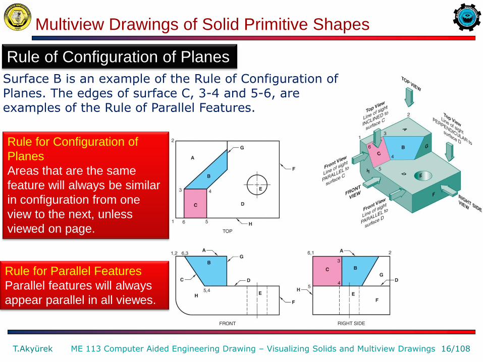
Rule of Configuration of Planes
Surface B is an example of the Rule of Configuration of Planes. The edges of surface C, 3-4 and 5-6, are examples of the Rule of Parallel Features.
Rule for Configuration of
Planes
Areas that are the same
feature will always be similar
in configuration from one
view to the next, unless
viewed on page.
Rule for Parallel Features
Parallel features will always
appear parallel in all viewes.
Fundamental Views of Surfaces for Visualization
T.Akyürek 17/108 ME 113 Computer Aided Engineering Drawing – Visualizing Solids and Multiview Drawings
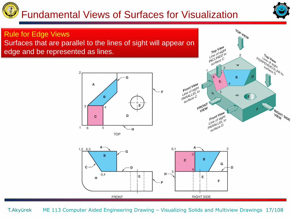
Rule for Edge Views
Surfaces that are parallel to the lines of sight will appear on
edge and be represented as lines.
Fundamental Views of Surfaces for Visualization
T.Akyürek 18/108 ME 113 Computer Aided Engineering Drawing – Visualizing Solids and Multiview Drawings
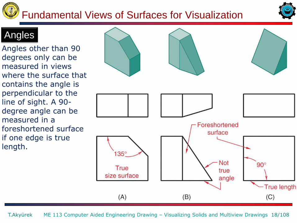
Angles
Angles other than 90 degrees only can be measured in views where the surface that contains the angle is perpendicular to the line of sight. A 90-degree angle can be measured in a foreshortened surface if one edge is true length.
Fundamental Views of Curved Surfaces for Visualization
T.Akyürek 19/108 ME 113 Computer Aided Engineering Drawing – Visualizing Solids and Multiview Drawings
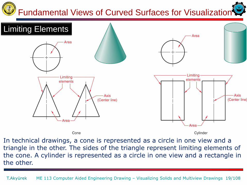
Limiting Elements
In technical drawings, a cone is represented as a circle in one view and a triangle in the other. The sides of the triangle represent limiting elements of the cone. A cylinder is represented as a circle in one view and a rectangle in the other.
Fundamental Views of Curved Surfaces for Visualization
T.Akyürek 20/108 ME 113 Computer Aided Engineering Drawing – Visualizing Solids and Multiview Drawings
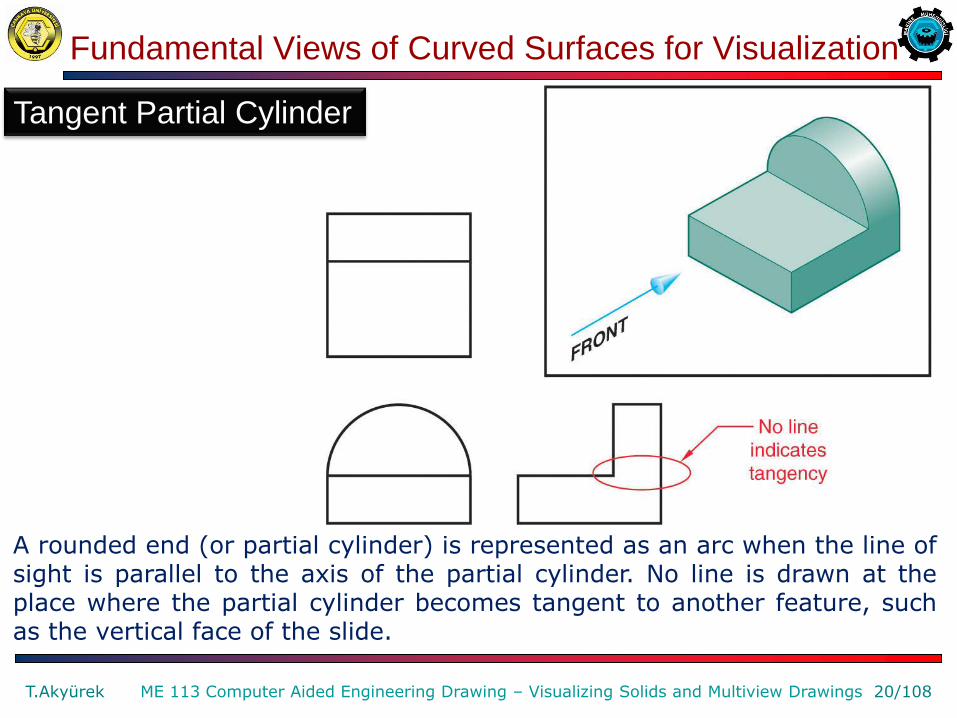
A rounded end (or partial cylinder) is represented as an arc when the line of sight is parallel to the axis of the partial cylinder. No line is drawn at the place where the partial cylinder becomes tangent to another feature, such as the vertical face of the slide.
Tangent Partial Cylinder

Fundamental Views of Curved Surfaces for Visualization
T.Akyürek 21/108 ME 113 Computer Aided Engineering Drawing – Visualizing Solids and Multiview Drawings
When the transition of a rounded end to another feature is not tangent, a line is used at the point of intersection.
Nontangent Partial Cylinder

Fundamental Views of Curved Surfaces for Visualization
T.Akyürek 22/108 ME 113 Computer Aided Engineering Drawing – Visualizing Solids and Multiview Drawings
An elliptical view of a circle is created when the circle is viewed at an oblique angle.
Elliptical Representation of a Circle
Fundamental Views of Curved Surfaces for Visualization
T.Akyürek 23/108 ME 113 Computer Aided Engineering Drawing – Visualizing Solids and Multiview Drawings
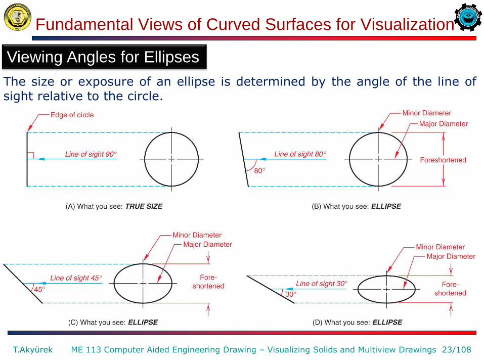
The size or exposure of an ellipse is determined by the angle of the line of sight relative to the circle.
Viewing Angles for Ellipses

Fundamental Views of Curved Surfaces for Visualization
T.Akyürek 24/108 ME 113 Computer Aided Engineering Drawing – Visualizing Solids and Multiview Drawings
Representation of Various Types of Machined Holes

Fundamental Views of Curved Surfaces for Visualization
T.Akyürek 25/108 ME 113 Computer Aided Engineering Drawing – Visualizing Solids and Multiview Drawings
Representation of Various Types of Machined Holes
Fundamental Views of Curved Surfaces for Visualization
T.Akyürek 26/108 ME 113 Computer Aided Engineering Drawing – Visualizing Solids and Multiview Drawings
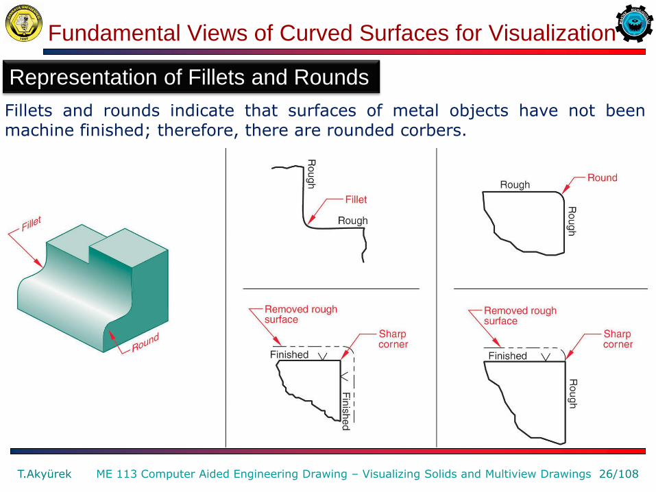
Representation of Fillets and Rounds
Fillets and rounds indicate that surfaces of metal objects have not been machine finished; therefore, there are rounded corbers.

Fundamental Views of Fillets and Rounds for Visualization
T.Akyürek 27/108 ME 113 Computer Aided Engineering Drawing – Visualizing Solids and Multiview Drawings
Representing Filleted and Rounded Corners
Lines tangent to a fillet or rounded are constructed and then extended, to create a sharp corner. The location of sharp corner is projected to the adjacent view, to determine where to place representative lines indicating a change of planes.
Fundamental Views of Fillets and Rounds for Visualization
T.Akyürek 28/108 ME 113 Computer Aided Engineering Drawing – Visualizing Solids and Multiview Drawings
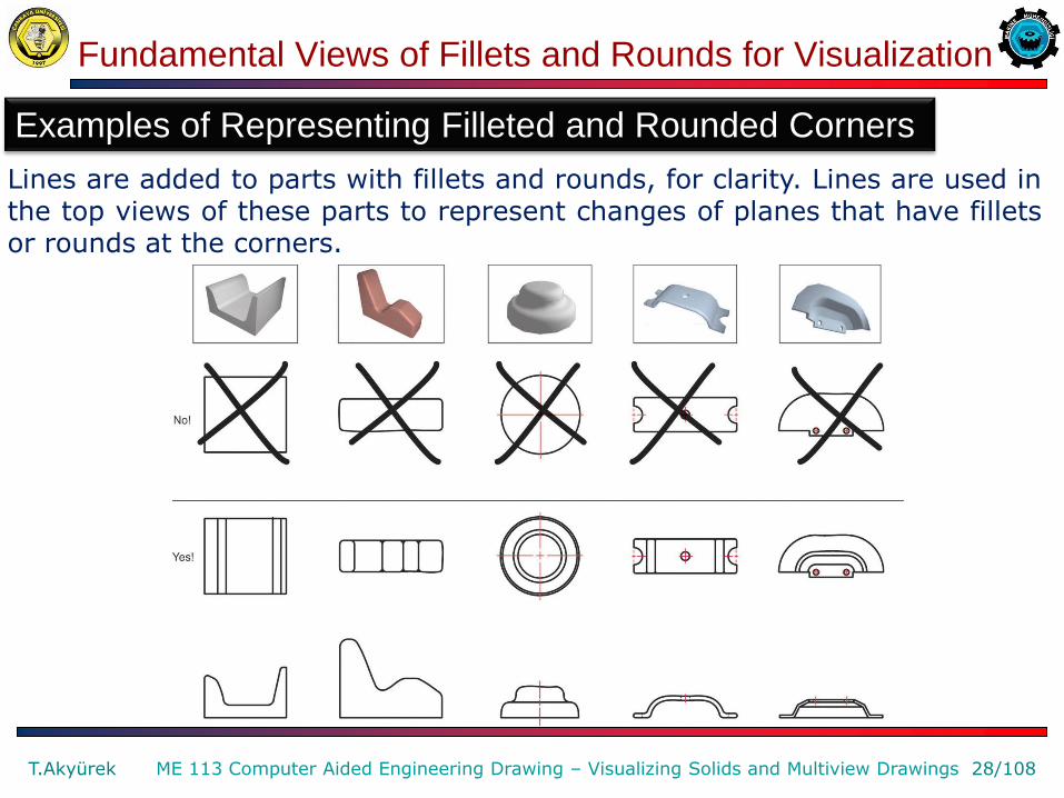
Examples of Representing Filleted and Rounded Corners
Lines are added to parts with fillets and rounds, for clarity. Lines are used in the top views of these parts to represent changes of planes that have fillets or rounds at the corners.
Fundamental Views of Chamfers for Visualization
T.Akyürek 29/108 ME 113 Computer Aided Engineering Drawing – Visualizing Solids and Multiview Drawings
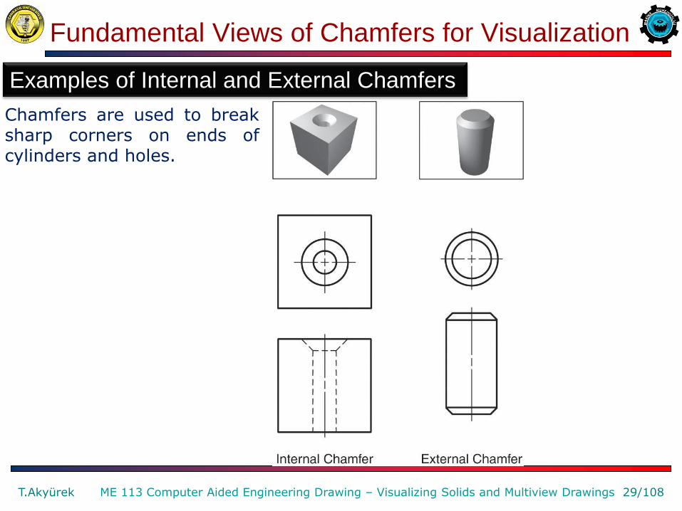
Examples of Internal and External Chamfers
Chamfers are used to break sharp corners on ends of cylinders and holes.
Fundamental Views of Runouts for Visualization
T.Akyürek 30/108 ME 113 Computer Aided Engineering Drawing – Visualizing Solids and Multiview Drawings
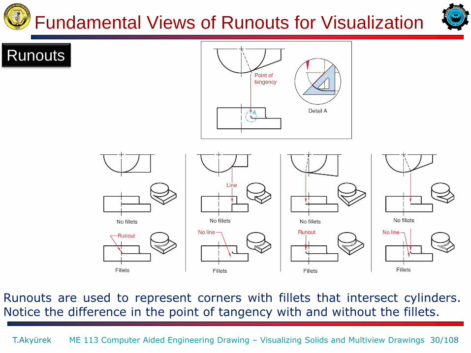
Runouts
Runouts are used to represent corners with fillets that intersect cylinders. Notice the difference in the point of tangency with and without the fillets.
Fundamental Views of Runouts for Visualization
T.Akyürek 31/108 ME 113 Computer Aided Engineering Drawing – Visualizing Solids and Multiview Drawings
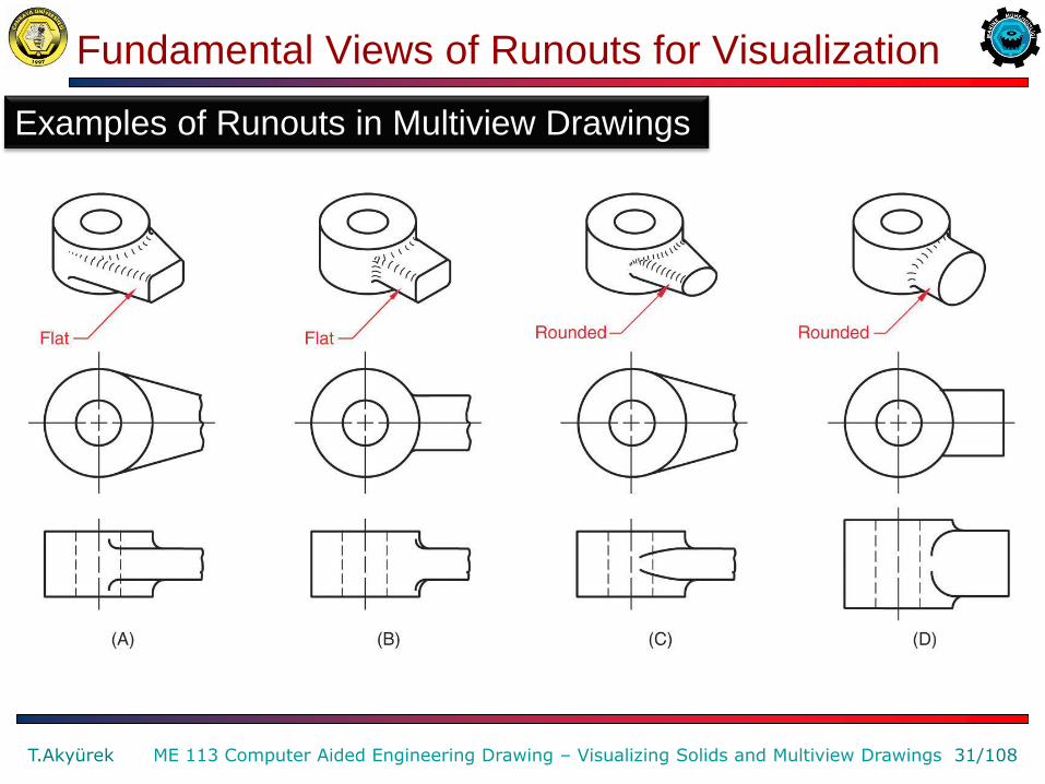
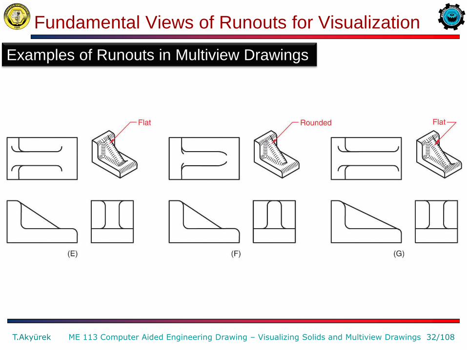
Examples of Runouts in Multiview Drawings
Fundamental Views of Runouts for Visualization
T.Akyürek 32/108 ME 113 Computer Aided Engineering Drawing – Visualizing Solids and Multiview Drawings
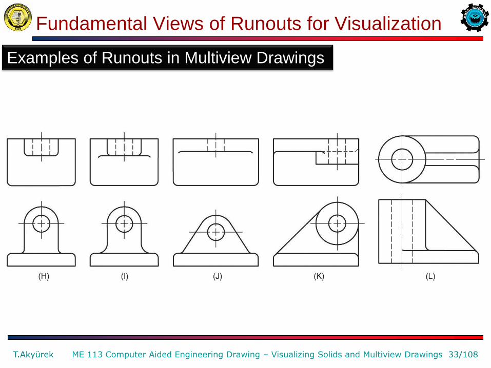
Examples of Runouts in Multiview Drawings
Fundamental Views of Runouts for Visualization
T.Akyürek 33/108 ME 113 Computer Aided Engineering Drawing – Visualizing Solids and Multiview Drawings
Examples of Runouts in Multiview Drawings
Fundamental Views of Runouts for Visualization
T.Akyürek 34/108 ME 113 Computer Aided Engineering Drawing – Visualizing Solids and Multiview Drawings
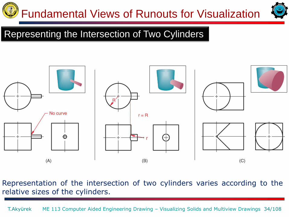
Representing the Intersection of Two Cylinders
Representation of the intersection of two cylinders varies according to the relative sizes of the cylinders.
Fundamental Views of Runouts for Visualization
T.Akyürek 35/108 ME 113 Computer Aided Engineering Drawing – Visualizing Solids and Multiview Drawings
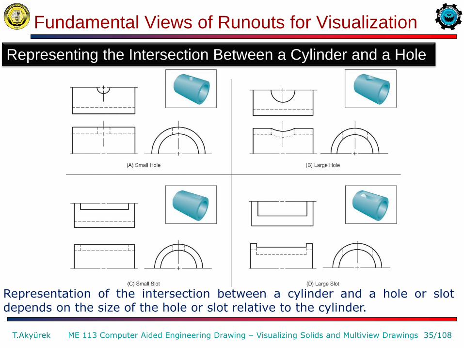
Representing the Intersection Between a Cylinder and a Hole
Representation of the intersection between a cylinder and a hole or slot depends on the size of the hole or slot relative to the cylinder.
Revolution Conventions
T.Akyürek 36/108 ME 113 Computer Aided Engineering Drawing – Visualizing Solids and Multiview Drawings
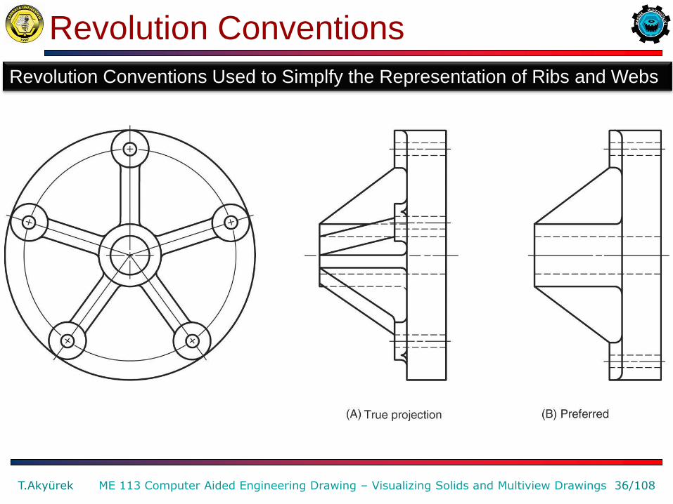
Revolution Conventions Used to Simplfy the Representation of Ribs and Webs
Revolution Conventions
T.Akyürek 37/108 ME 113 Computer Aided Engineering Drawing – Visualizing Solids and Multiview Drawings
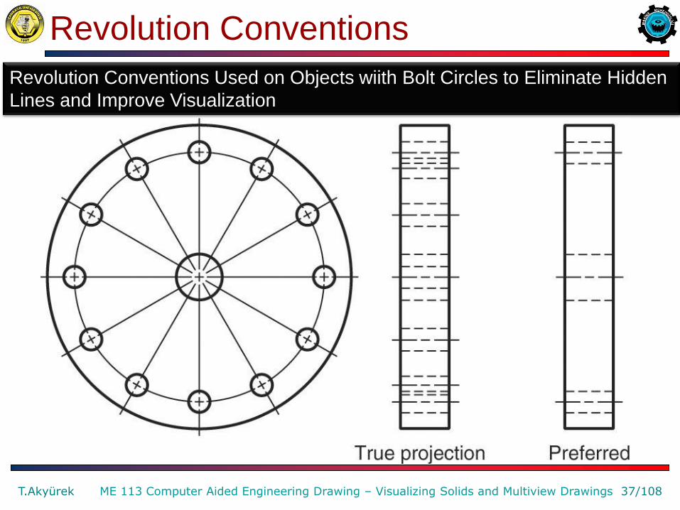
Revolution Conventions Used on Objects wiith Bolt Circles to Eliminate Hidden
Lines and Improve Visualization

Revolution Conventions
T.Akyürek 38/108 ME 113 Computer Aided Engineering Drawing – Visualizing Solids and Multiview Drawings
Revolution Conventions Used to Simplfy the Representation of Arms

Visualization for Design
T.Akyürek 39/108 ME 113 Computer Aided Engineering Drawing – Visualizing Solids and Multiview Drawings
Design Visualization
Leonardo da Vinci used drawings as a means of visualizing his designs.
Visualization for Design
T.Akyürek 40/108 ME 113 Computer Aided Engineering Drawing – Visualizing Solids and Multiview Drawings
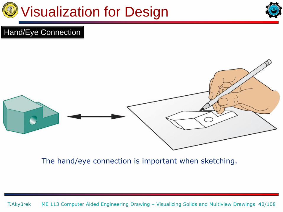
Hand/Eye Connection
The hand/eye connection is important when sketching.

Visualization for Design
T.Akyürek 41/108 ME 113 Computer Aided Engineering Drawing – Visualizing Solids and Multiview Drawings
Hand/Eye/Mind Connection
The hand/eye/mind connection more accurately describe the processes used to make sketches. The mind forms a mental picture of existing or nonexisting objects, which can then be sketched. The feedback loop between the mind and the hand is so powerful that the object need not exist.

Solid Object Features
T.Akyürek 42/108 ME 113 Computer Aided Engineering Drawing – Visualizing Solids and Multiview Drawings
These rectangular prism and cylinder primitives show important features: edge, face, vertex, and limiting element.
Solid Object Features
T.Akyürek 43/108 ME 113 Computer Aided Engineering Drawing – Visualizing Solids and Multiview Drawings
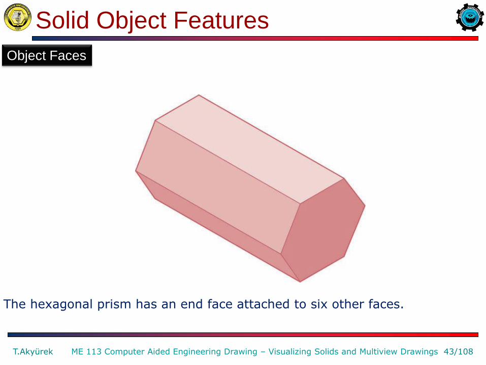
The hexagonal prism has an end face attached to six other faces.
Object Faces

Solid Object Visualization
T.Akyürek 44/108 ME 113 Computer Aided Engineering Drawing – Visualizing Solids and Multiview Drawings
Additive combinations of primitives can be used to create new forms. This example shows acceptable (A and B) and unacceptable © ways a cylinder could be added to a cube to form a new object.
Combinations and Negative Solids
Combining Solid Objects
Solid Object Visualization
T.Akyürek 45/108 ME 113 Computer Aided Engineering Drawing – Visualizing Solids and Multiview Drawings
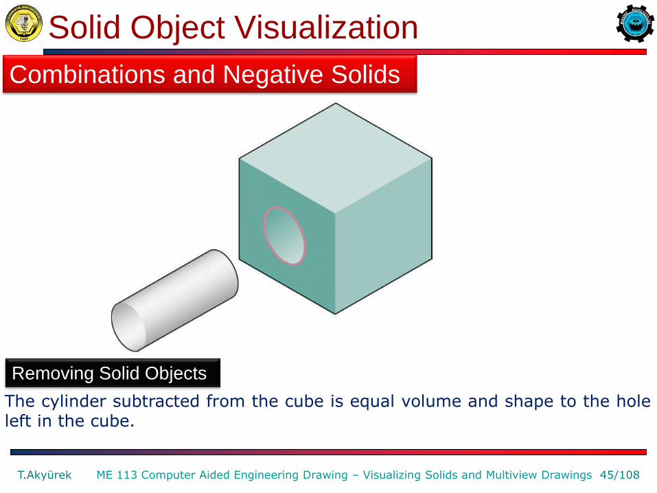
The cylinder subtracted from the cube is equal volume and shape to the hole left in the cube.
Combinations and Negative Solids
Removing Solid Objects

Solid Object Visualization
T.Akyürek 46/108 ME 113 Computer Aided Engineering Drawing – Visualizing Solids and Multiview Drawings
When a square prism is subtarcted from the cube, the edges of the hole match the end face of the square prism.
Combinations and Negative Solids
Subtracting a Square Prism
Solid Object Visualization
T.Akyürek 47/108 ME 113 Computer Aided Engineering Drawing – Visualizing Solids and Multiview Drawings
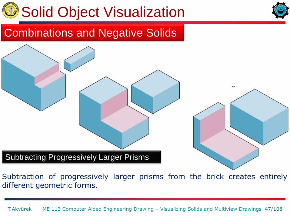
Subtraction of progressively larger prisms from the brick creates entirely different geometric forms.
Combinations and Negative Solids
Subtracting Progressively Larger Prisms
Solid Object Visualization
T.Akyürek 48/108 ME 113 Computer Aided Engineering Drawing – Visualizing Solids and Multiview Drawings
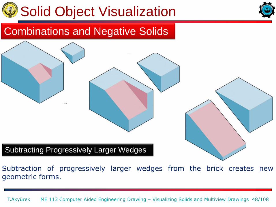
Subtraction of progressively larger wedges from the brick creates new geometric forms.
Combinations and Negative Solids
Subtracting Progressively Larger Wedges
Solid Object Visualization
T.Akyürek 49/108 ME 113 Computer Aided Engineering Drawing – Visualizing Solids and Multiview Drawings
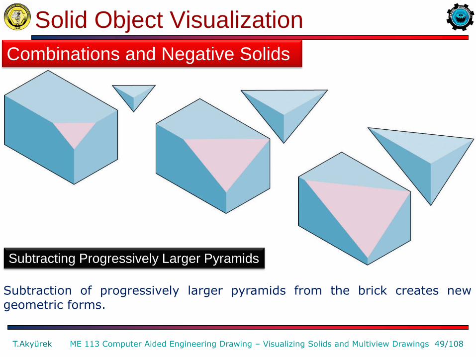
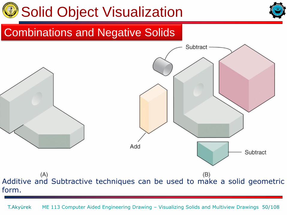
Subtraction of progressively larger pyramids from the brick creates new geometric forms.
Combinations and Negative Solids
Subtracting Progressively Larger Pyramids
Solid Object Visualization
T.Akyürek 50/108 ME 113 Computer Aided Engineering Drawing – Visualizing Solids and Multiview Drawings
Additive and Subtractive techniques can be used to make a solid geometric form.
Combinations and Negative Solids
Solid Object Visualization
T.Akyürek 51/108 ME 113 Computer Aided Engineering Drawing – Visualizing Solids and Multiview Drawings
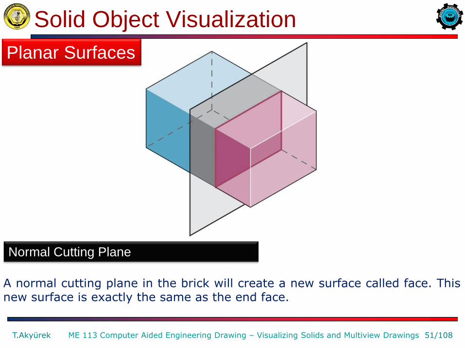
A normal cutting plane in the brick will create a new surface called face. This new surface is exactly the same as the end face.
Planar Surfaces
Normal Cutting Plane

Solid Object Visualization
T.Akyürek 52/108 ME 113 Computer Aided Engineering Drawing – Visualizing Solids and Multiview Drawings
A cutting plane is rotated about a single axis in the brick. This creates inclined faces until the plane has rotated 90 degrees, creating a face normal to the top view.
Planar Surfaces
Cutting Plane Rotated About Single Axis
Solid Object Visualization
T.Akyürek 53/108 ME 113 Computer Aided Engineering Drawing – Visualizing Solids and Multiview Drawings
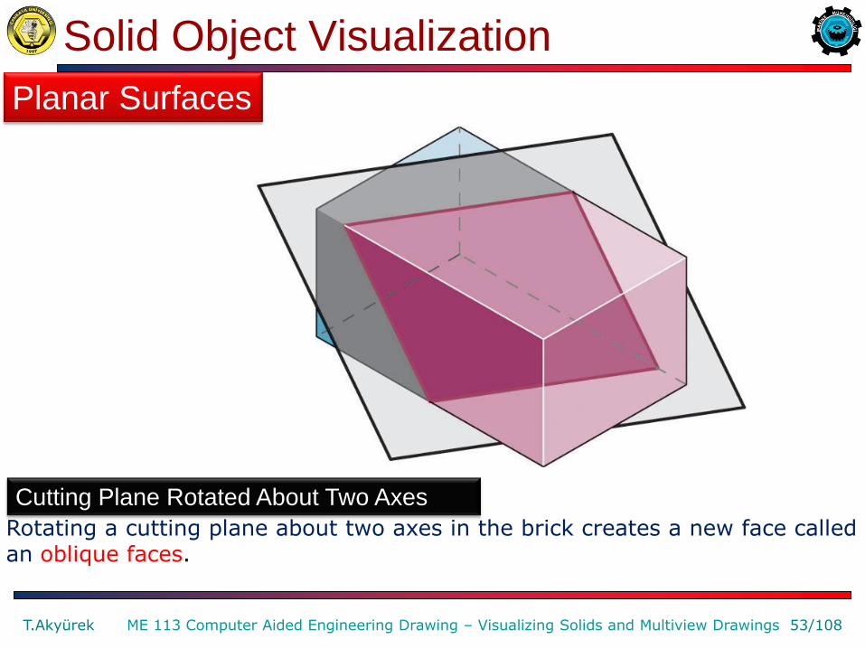
Rotating a cutting plane about two axes in the brick creates a new face called an oblique faces.
Planar Surfaces
Cutting Plane Rotated About Two Axes
Solid Object Visualization
T.Akyürek 54/108 ME 113 Computer Aided Engineering Drawing – Visualizing Solids and Multiview Drawings
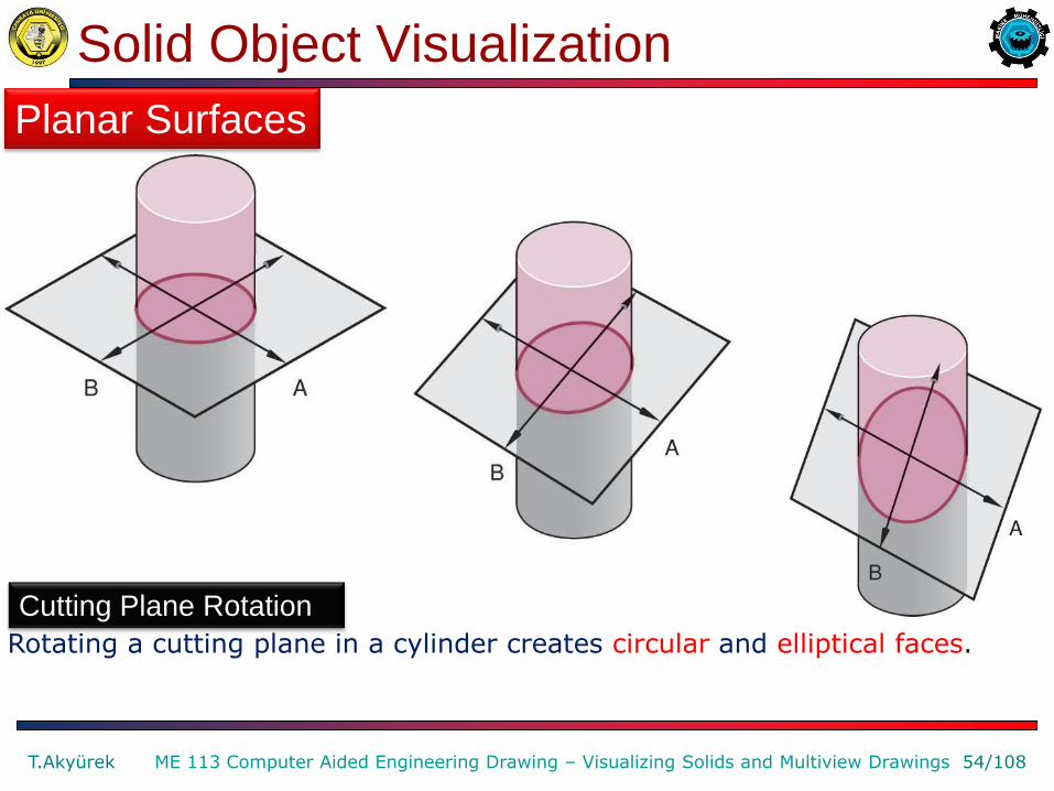
Rotating a cutting plane in a cylinder creates circular and elliptical faces.
Planar Surfaces
Cutting Plane Rotation
Solid Object Visualization
T.Akyürek 55/108 ME 113 Computer Aided Engineering Drawing – Visualizing Solids and Multiview Drawings
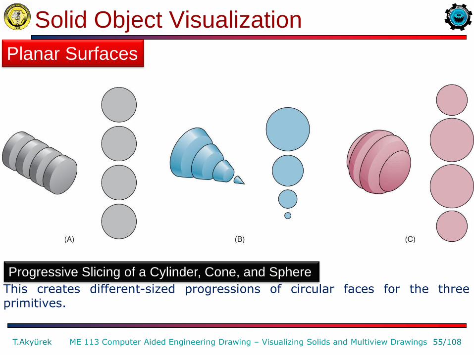
This creates different-sized progressions of circular faces for the three primitives.
Planar Surfaces
Progressive Slicing of a Cylinder, Cone, and Sphere
Solid Object Visualization
T.Akyürek 56/108 ME 113 Computer Aided Engineering Drawing – Visualizing Solids and Multiview Drawings
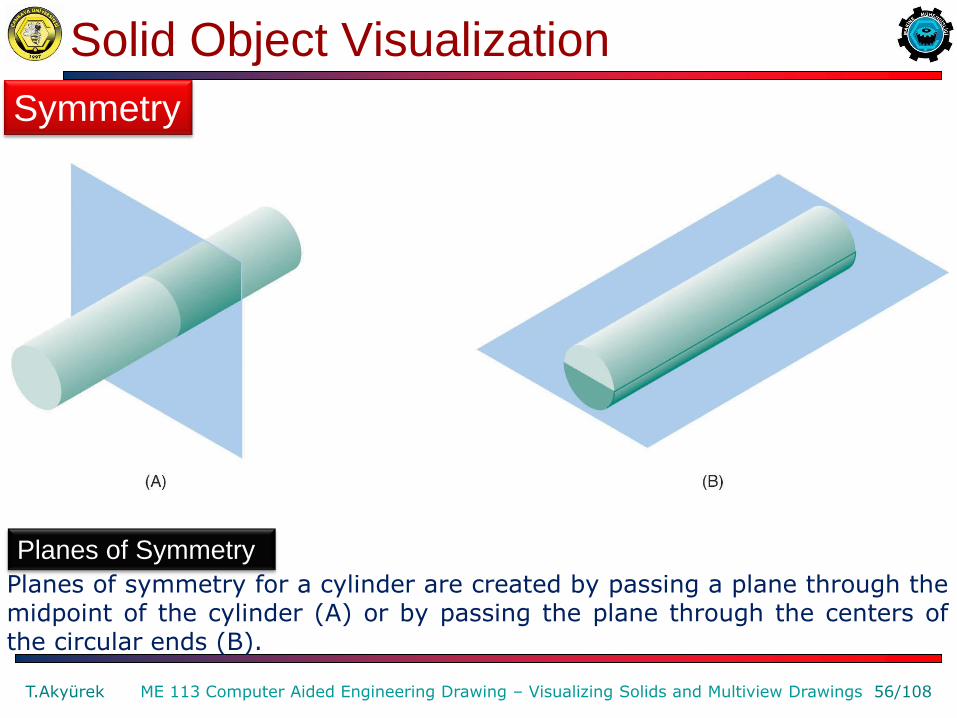
Planes of symmetry for a cylinder are created by passing a plane through the midpoint of the cylinder (A) or by passing the plane through the centers of the circular ends (B).
Symmetry
Planes of Symmetry
Solid Object Visualization
T.Akyürek 57/108 ME 113 Computer Aided Engineering Drawing – Visualizing Solids and Multiview Drawings
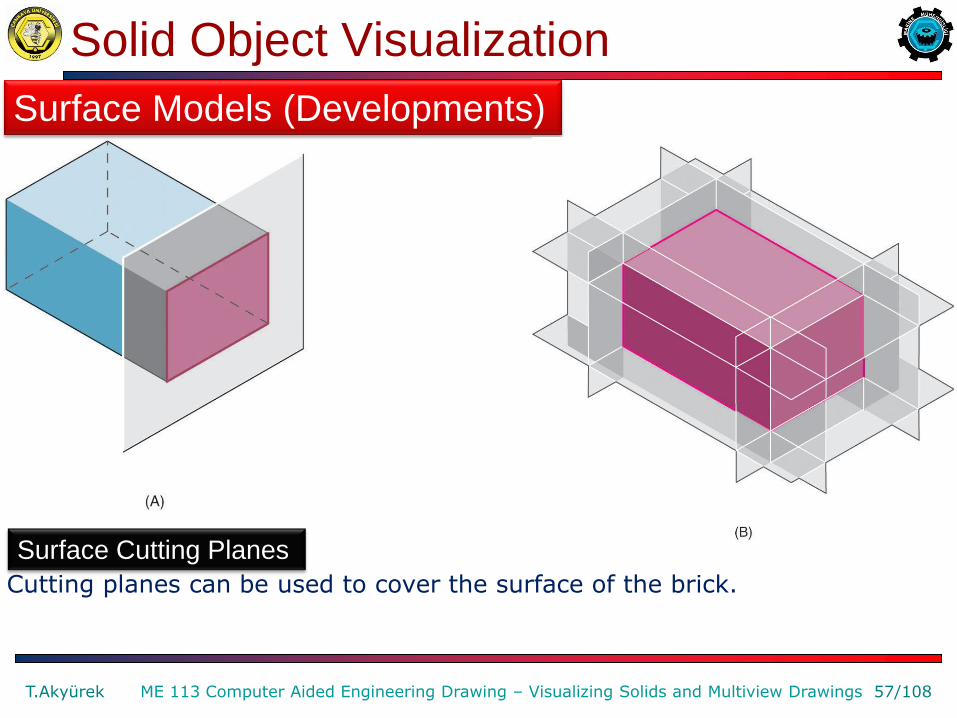
Cutting planes can be used to cover the surface of the brick.
Surface Models (Developments)
Surface Cutting Planes
Solid Object Visualization
T.Akyürek 58/108 ME 113 Computer Aided Engineering Drawing – Visualizing Solids and Multiview Drawings
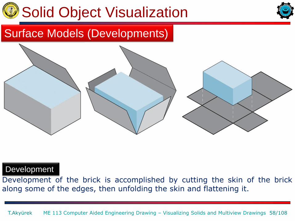
Development of the brick is accomplished by cutting the skin of the brick along some of the edges, then unfolding the skin and flattening it.
Surface Models (Developments)
Development

Solid Object Visualization
T.Akyürek 59/108 ME 113 Computer Aided Engineering Drawing – Visualizing Solids and Multiview Drawings
Brick edges that are attached to form the brick skin are indicated by dashed lines.
Surface Models (Developments)
There are many alternative methods of creating the development for the brick, such as the one shown here.
Solid Object Visualization
T.Akyürek 60/108 ME 113 Computer Aided Engineering Drawing – Visualizing Solids and Multiview Drawings
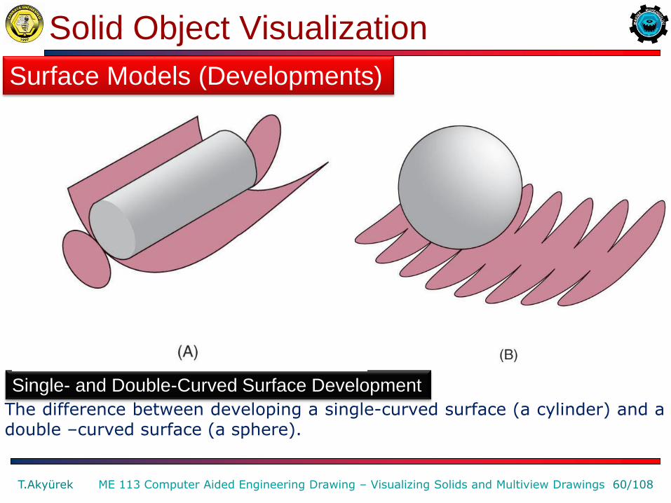
The difference between developing a single-curved surface (a cylinder) and a double –curved surface (a sphere).
Surface Models (Developments)
Single- and Double-Curved Surface Development
Multiview Drawing Visualization
T.Akyürek 61/108 ME 113 Computer Aided Engineering Drawing – Visualizing Solids and Multiview Drawings
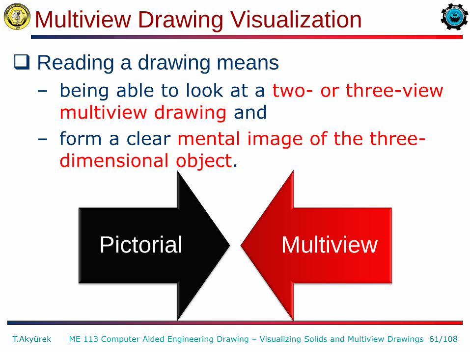
Reading a drawing means
– being able to look at a two- or three-view multiview drawing and
– form a clear mental image of the three-dimensional object.
Pictorial Multiview

Techniques to Visualize Geometry of an Object
1 • Projection Studies
2 • Physical Model Construction
3 • Adjacent Areas
4 • Similar Shapes
5 • Surface Labeling
6 • Missing Lines
7 • Vertex Labeling
8 • Analysis by Solids
9 • Analysis by Surfaces
T.Akyürek 62/108 ME 113 Computer Aided Engineering Drawing – Visualizing Solids and Multiview Drawings

Techniques to Visualize Geometry of an Object
T.Akyürek 63/108 ME 113 Computer Aided Engineering Drawing – Visualizing Solids and Multiview Drawings
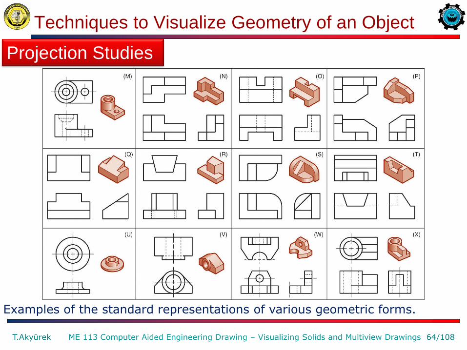
Examples of the standard representations of various geometric forms.
Projection Studies
Techniques to Visualize Geometry of an Object
T.Akyürek 64/108 ME 113 Computer Aided Engineering Drawing – Visualizing Solids and Multiview Drawings
Examples of the standard representations of various geometric forms.
Projection Studies
Techniques to Visualize Geometry of an Object
T.Akyürek 65/108 ME 113 Computer Aided Engineering Drawing – Visualizing Solids and Multiview Drawings
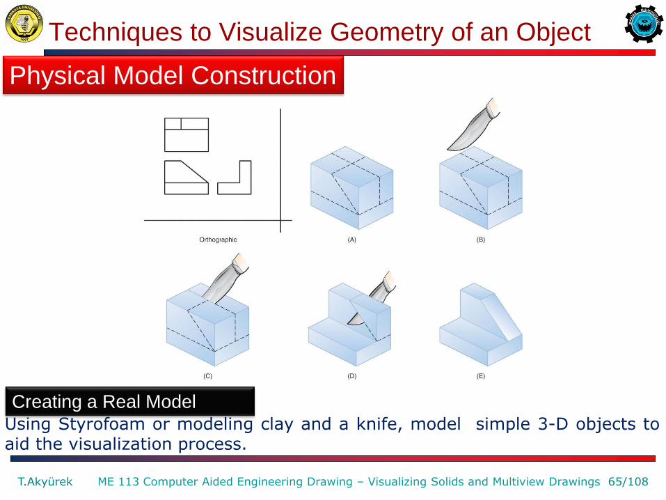
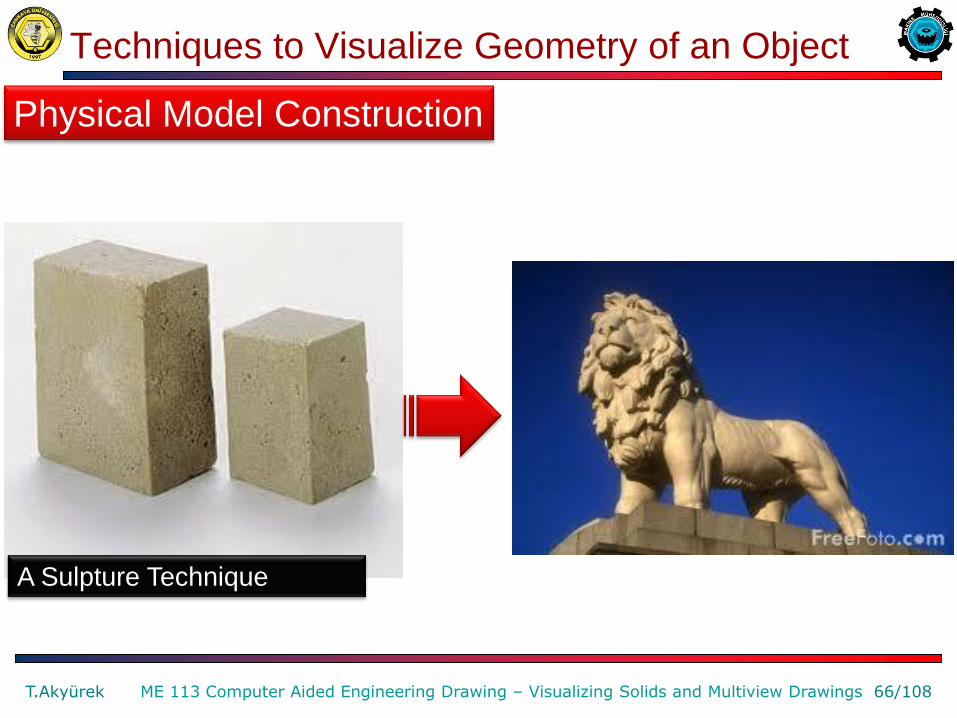
Using Styrofoam or modeling clay and a knife, model simple 3-D objects to aid the visualization process.
Physical Model Construction
Creating a Real Model
Techniques to Visualize Geometry of an Object
T.Akyürek 66/108 ME 113 Computer Aided Engineering Drawing – Visualizing Solids and Multiview Drawings
Physical Model Construction
A Sulpture Technique

Techniques to Visualize Geometry of an Object
T.Akyürek 67/108 ME 113 Computer Aided Engineering Drawing – Visualizing Solids and Multiview Drawings
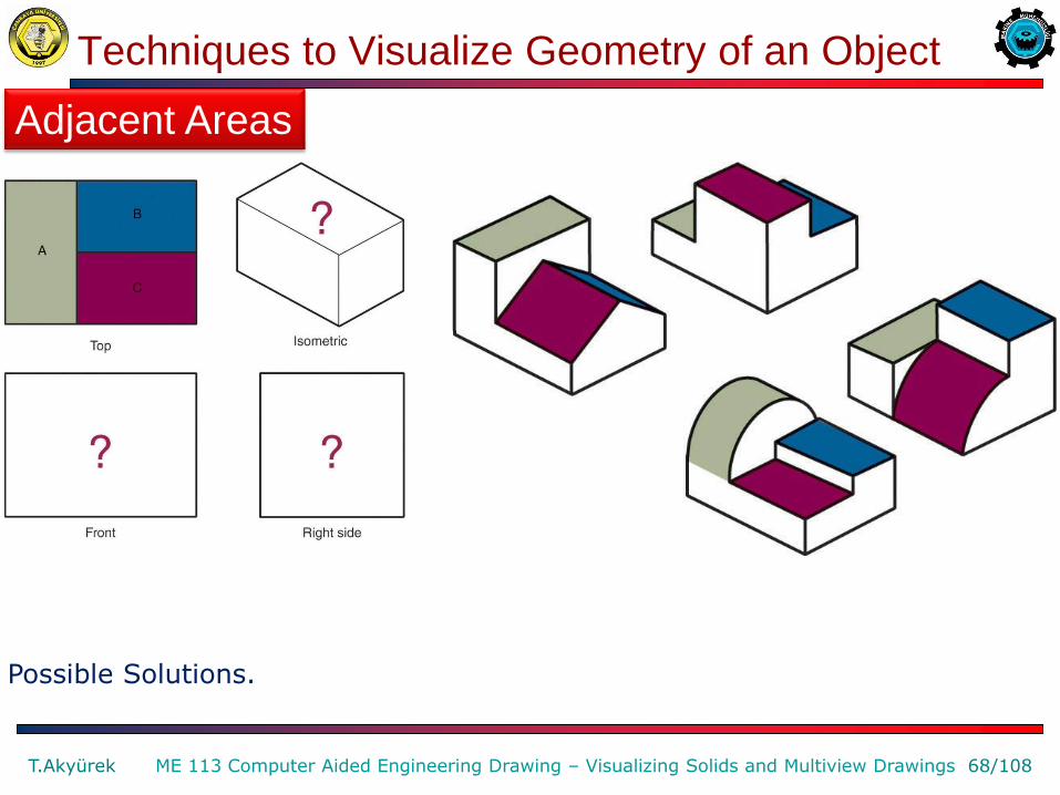
Given the top view, make isometric sketches of possible 3-D objects.
Adjacent Areas
Techniques to Visualize Geometry of an Object
T.Akyürek 68/108 ME 113 Computer Aided Engineering Drawing – Visualizing Solids and Multiview Drawings
Possible Solutions.
Adjacent Areas

Techniques to Visualize Geometry of an Object
T.Akyürek 69/108 ME 113 Computer Aided Engineering Drawing – Visualizing Solids and Multiview Drawings
Similar-shaped surfaces will retain their basic configuration in all views, unless viewed on edge. Notice that the number of edges of a face remains constant in all the views and that edges parallel in one view remain parallel in other views.
Similar Shapes
Similar-Shaped Surfaces

Techniques to Visualize Geometry of an Object
T.Akyürek 70/108 ME 113 Computer Aided Engineering Drawing – Visualizing Solids and Multiview Drawings
Similar-shaped surfaces will retain their basic configuration in all views, unless viewed on edge. Notice that the number of edges of a face remains constant in all the views and that edges parallel in one view remain parallel in other views.
Similar Shapes
Similar-Shaped Surfaces

Techniques to Visualize Geometry of an Object
T.Akyürek 71/108 ME 113 Computer Aided Engineering Drawing – Visualizing Solids and Multiview Drawings
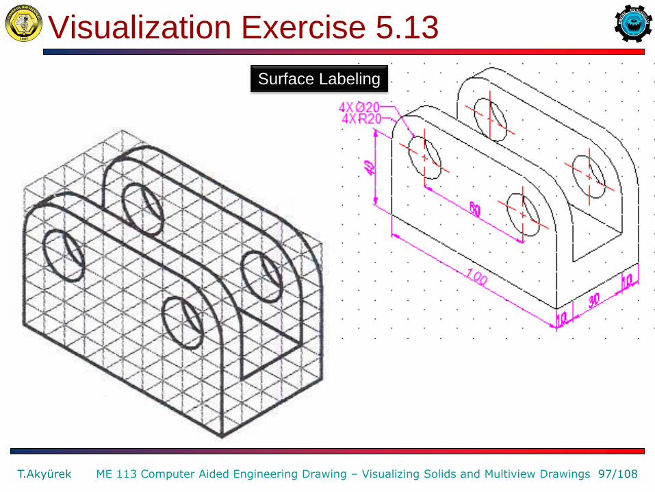
To check the accuracy of multiview drawings, surfaces can be labeled and compared to those in the pictorial view.
Surface Labeling
Techniques to Visualize Geometry of an Object
T.Akyürek 72/108 ME 113 Computer Aided Engineering Drawing – Visualizing Solids and Multiview Drawings
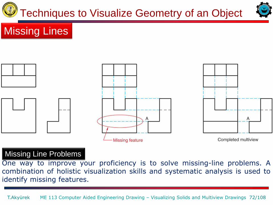
One way to improve your proficiency is to solve missing-line problems. A combination of holistic visualization skills and systematic analysis is used to identify missing features.
Missing Lines
Missing Line Problems
Techniques to Visualize Geometry of an Object
T.Akyürek 73/108 ME 113 Computer Aided Engineering Drawing – Visualizing Solids and Multiview Drawings
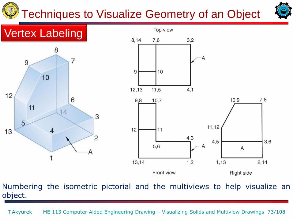
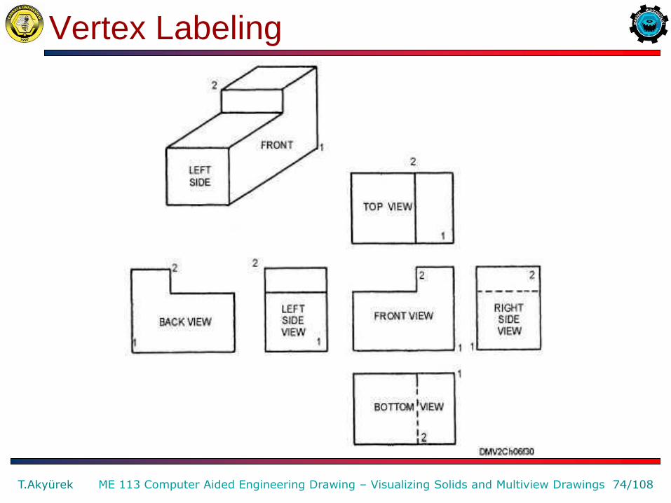
Numbering the isometric pictorial and the multiviews to help visualize an object.
Vertex Labeling
Vertex Labeling
T.Akyürek 74/108 ME 113 Computer Aided Engineering Drawing – Visualizing Solids and Multiview Drawings

Techniques to Visualize Geometry of an Object
T.Akyürek 75/108 ME 113 Computer Aided Engineering Drawing – Visualizing Solids and Multiview Drawings
A complex object can be visualized by decomposing it into simpler geometric forms.
Analysis by Solids

Analysis by Solids
T.Akyürek 76/108 ME 113 Computer Aided Engineering Drawing – Visualizing Solids and Multiview Drawings

Analysis by Solids
T.Akyürek 77/108 ME 113 Computer Aided Engineering Drawing – Visualizing Solids and Multiview Drawings

Analysis by Solids
T.Akyürek 78/108 ME 113 Computer Aided Engineering Drawing – Visualizing Solids and Multiview Drawings

Analysis by Solids
T.Akyürek 79/108 ME 113 Computer Aided Engineering Drawing – Visualizing Solids and Multiview Drawings
Techniques to Visualize Geometry of an Object
T.Akyürek 80/108 ME 113 Computer Aided Engineering Drawing – Visualizing Solids and Multiview Drawings
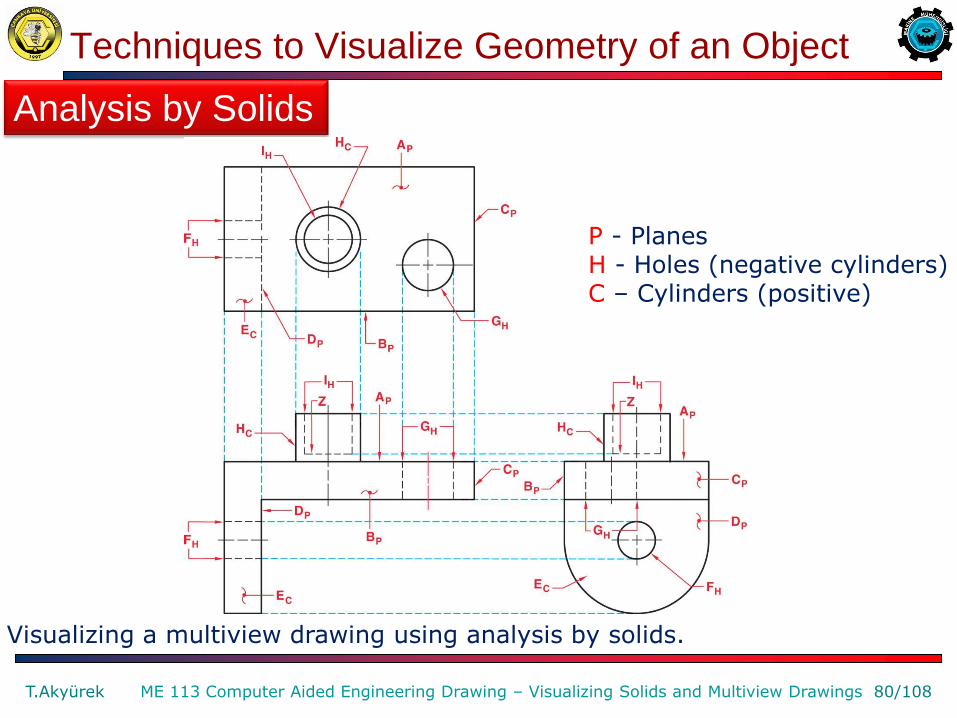
Visualizing a multiview drawing using analysis by solids.
Analysis by Solids
P - Planes H - Holes (negative cylinders) C – Cylinders (positive)

Techniques to Visualize Geometry of an Object
T.Akyürek 81/108 ME 113 Computer Aided Engineering Drawing – Visualizing Solids and Multiview Drawings
Analysis by Solids
P - Planes H - Holes (negative cylinders) C – Cylinders (positive)
Techniques to Visualize Geometry of an Object
T.Akyürek 82/108 ME 113 Computer Aided Engineering Drawing – Visualizing Solids and Multiview Drawings
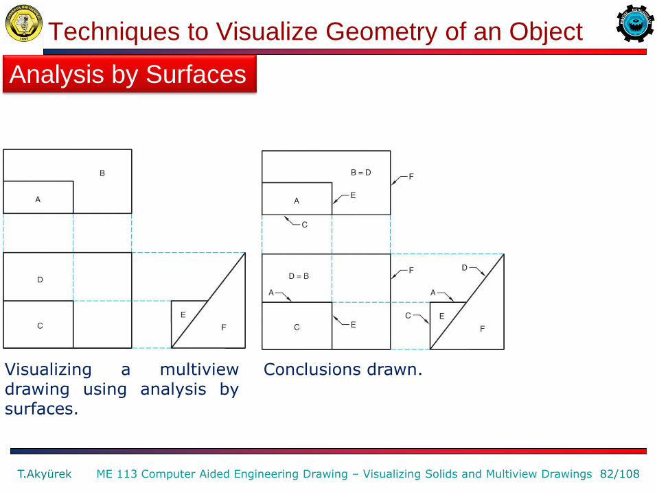
Visualizing a multiview drawing using analysis by surfaces.
Analysis by Surfaces
Conclusions drawn.

Techniques to Visualize Geometry of an Object
T.Akyürek 83/108 ME 113 Computer Aided Engineering Drawing – Visualizing Solids and Multiview Drawings
Visualizing a multiview drawing using analysis by surfaces.
Analysis by Surfaces
Conclusions drawn.
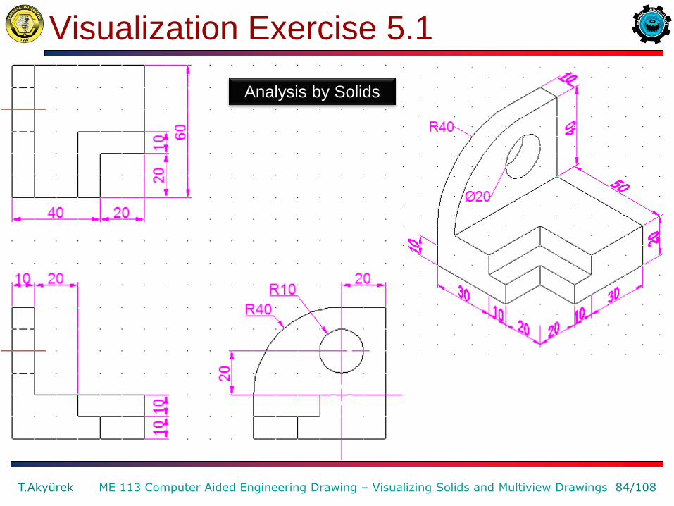
Visualization Exercise 5.1
T.Akyürek 84/108 ME 113 Computer Aided Engineering Drawing – Visualizing Solids and Multiview Drawings
Analysis by Solids

Visualization Exercise 5.2
T.Akyürek 85/108 ME 113 Computer Aided Engineering Drawing – Visualizing Solids and Multiview Drawings
Surface Labeling

Visualization Exercise 5.3
T.Akyürek 86/108 ME 113 Computer Aided Engineering Drawing – Visualizing Solids and Multiview Drawings
3
5
6
7
1
7
3 4
1 7 8
4
5
Surface Labeling
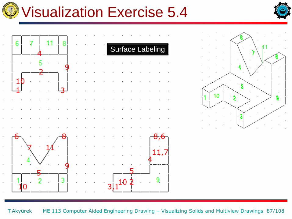
Visualization Exercise 5.4
T.Akyürek 87/108 ME 113 Computer Aided Engineering Drawing – Visualizing Solids and Multiview Drawings
5
2 3,1
8,6
10
4 11,7
9
8 6
7 11
10
5
1 3
10
2 9
4 Surface Labeling
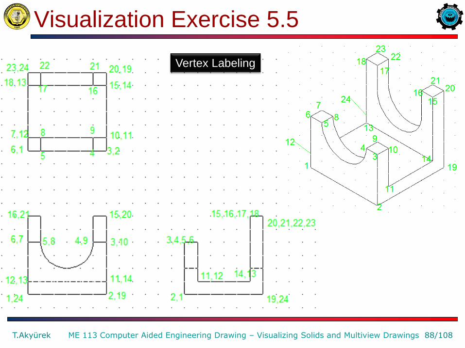
Visualization Exercise 5.5
T.Akyürek 88/108 ME 113 Computer Aided Engineering Drawing – Visualizing Solids and Multiview Drawings
Vertex Labeling
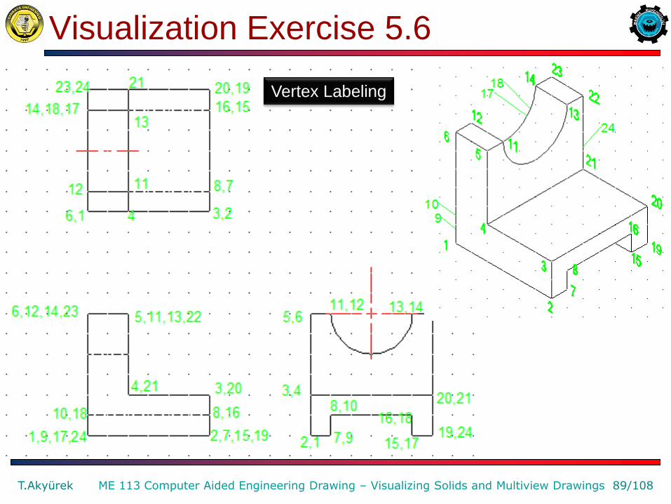
Visualization Exercise 5.6
T.Akyürek 89/108 ME 113 Computer Aided Engineering Drawing – Visualizing Solids and Multiview Drawings
Vertex Labeling

Visualization Exercise 5.7
T.Akyürek 90/108 ME 113 Computer Aided Engineering Drawing – Visualizing Solids and Multiview Drawings
Vertex Labeling
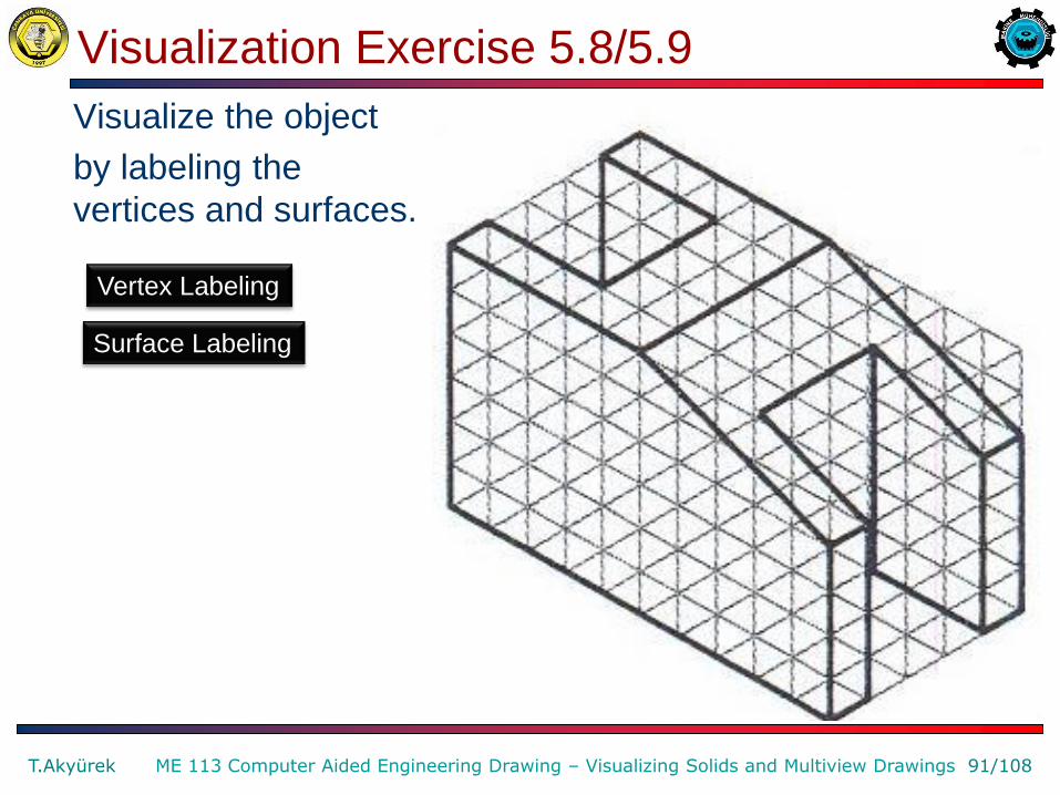
Visualization Exercise 5.8/5.9
Visualize the object
by labeling the
vertices and surfaces.
T.Akyürek 91/108 ME 113 Computer Aided Engineering Drawing – Visualizing Solids and Multiview Drawings
Vertex Labeling
Surface Labeling
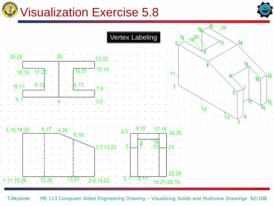
Visualization Exercise 5.8
T.Akyürek 92/108 ME 113 Computer Aided Engineering Drawing – Visualizing Solids and Multiview Drawings
Vertex Labeling
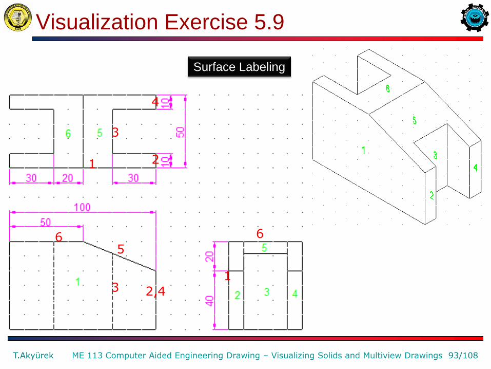
Visualization Exercise 5.9
T.Akyürek 93/108 ME 113 Computer Aided Engineering Drawing – Visualizing Solids and Multiview Drawings
3
5 6
2,4
1
3
2
4
1
6
Surface Labeling
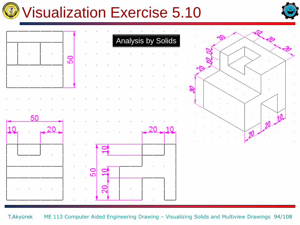
Visualization Exercise 5.10
T.Akyürek 94/108 ME 113 Computer Aided Engineering Drawing – Visualizing Solids and Multiview Drawings
Analysis by Solids

Visualization Exercise 5.12
T.Akyürek 95/108 ME 113 Computer Aided Engineering Drawing – Visualizing Solids and Multiview Drawings
Vertex Labeling

Visualization Exercise 5.12
T.Akyürek 96/108 ME 113 Computer Aided Engineering Drawing – Visualizing Solids and Multiview Drawings
Vertex Labeling
Visualization Exercise 5.13
T.Akyürek 97/108 ME 113 Computer Aided Engineering Drawing – Visualizing Solids and Multiview Drawings
Surface Labeling
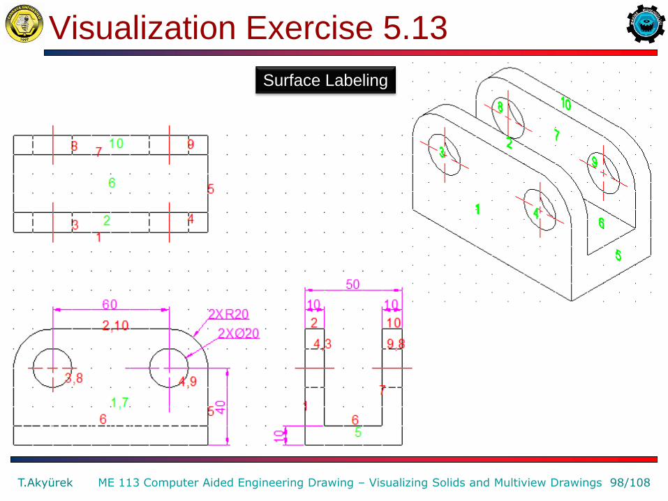
Visualization Exercise 5.13
T.Akyürek 98/108 ME 113 Computer Aided Engineering Drawing – Visualizing Solids and Multiview Drawings
Surface Labeling

Visualization Exercise 5.15
T.Akyürek 99/108 ME 113 Computer Aided Engineering Drawing – Visualizing Solids and Multiview Drawings
Analysis by Solids

Visualization Exercise 5.15
T.Akyürek 100/108 ME 113 Computer Aided Engineering Drawing – Visualizing Solids and Multiview Drawings
Analysis by Solids
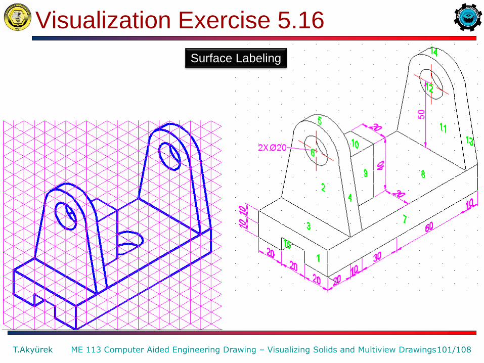
Visualization Exercise 5.16
T.Akyürek 101/108 ME 113 Computer Aided Engineering Drawing – Visualizing Solids and Multiview Drawings
Surface Labeling

Problem 5.21 (Figure 161A)
T.Akyürek 102/108 ME 113 Computer Aided Engineering Drawing – Visualizing Solids and Multiview Drawings
Surface Labeling Match the given surface letter from the pictorial drawing with the corresponding surface number from the multiview drawing for each view.
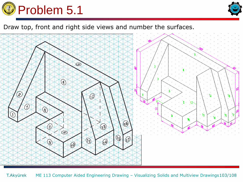
Problem 5.1
T.Akyürek 103/108 ME 113 Computer Aided Engineering Drawing – Visualizing Solids and Multiview Drawings
Draw top, front and right side views and number the surfaces.

Problem 5.1
T.Akyürek 104/108 ME 113 Computer Aided Engineering Drawing – Visualizing Solids and Multiview Drawings
Surface Labeling

Motor Plate
T.Akyürek 105/108 ME 113 Computer Aided Engineering Drawing – Visualizing Solids and Multiview Drawings
Given the pictorials, sketch or draw using CAD the multiviews and 3-D CAD model.

Seat
T.Akyürek 106/108 ME 113 Computer Aided Engineering Drawing – Visualizing Solids and Multiview Drawings
Given the pictorials, sketch or draw using CAD the multiviews and 3-D CAD model.
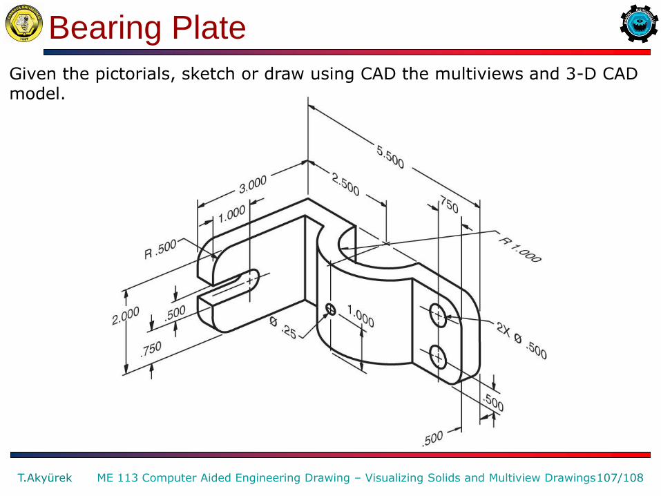
Bearing Plate
T.Akyürek 107/108 ME 113 Computer Aided Engineering Drawing – Visualizing Solids and Multiview Drawings
Given the pictorials, sketch or draw using CAD the multiviews and 3-D CAD model.

English – Turkish Dictionary
visualizing Görüntüleme,
gözde canlandırma
solid Katı (cisim) cylinder silindir
Illustraritve Açıklayıcı, aydınlatıcı bulk Yığın, kütle,
hacim
union birleşim
difference fark intersection kesişim wedge kama
transform dönüşüm model Kalıp, örnek block kütük
sculpture Heykel, heykeltraşlık analysis İnceleme, analiz prismatic Prizma şeklinde
basic Ana, esas virtual sanal corner köşe
surface yüzey cone koni torus halka
hole delik accuracy doğruluk
T.Akyürek 108/108 ME 113 Computer Aided Engineering Drawing – Visualizing Solids and Multiview Drawings