measurement and control technology - … · measurement & control technology ld didactic t 8...
TRANSCRIPT

CATALOG T8
MEASUREMENT AND CONTROL TECHNOLOGY
PHYSICS

Page 2 of 94 T 8.2
MEASUREMENT & CONTROL TECHNOLOGY
LD Didactic T 8
Content
Instrumentation, Control and Automation Technology
Instrumentation, Control and Automation are terms from the Automation field. The aim of this field is to monitor and operate technical events and production processes by means of automatic-running control systems. Through the use of machine controllers human beings are exempted from monotonous control and operation tasks. Frequently, technical systems have requirements for accuracy, quickness and reliability that can't be met by human beings. In many skilled occupations, the rapidly spreading Automation technique calls for a sound knowledge of sensors and experience in dealing with control circuits. I&C Technology from LD Didactic takes this development into account. The present complete catalogue T8 Instrumentation, Control & Automation introduces our extensive product range based on state of the art technology. The equipments, arranged by fields of study, contain the material subdivided according to fundamentals and industrial applications. As a rule, experiments are carried out with modular experiment boards or multimedia training courses. Print date: 23.08.2011
T 8.1
T 8.3
Industrial Control Technology
T 8.2
Basics of Control Technology
Measurement & Sensor Technology

Page 3 of 94 T 8.2
MEASUREMENT & CONTROL TECHNOLOGY
LD Didactic T 8
Content
Training Systems 4
Technical Data 6
Measurement and Sensors 11
Measurement and sensor technology courses impart skills necessary to measure the fundamental electrical quantities:
Current, voltage, frequency, etc.
As well as knowledge on the function of sensors:
Strength, temperature, revolutions, pressure etc.
An important component in the field of measurement technology is the present COM3LAB course Sensor Technology.
Basics of Control Technology 27
This field contains equipment for all skilled occupations requiring fundamentals or in-depth knowledge of control technology. In the experiments, technical models and electronic links with digital operation are used.
Industrial Control Technology 65
The field of Industrial Control Technology has been completely revised. Apart from an optimised, pneumatic instrumentation, the CASSY LAB 2 integration is particularly helpful here.
Equipment sets 86
Keywords 92
Symbols and abbreviations used in this catalogue:
Experiment manuals contained
Software contained
Accessory required
Battery required
Compatible to COM3LAB
USB support
Page 4 of 94 T 8.2
MEASUREMENT & CONTROL TECHNOLOGY
LD Didactic T 8
Training Systems
Plug-In System and Training Panels
The training systems described in this catalogue can be classified into three categories:
STE- Plug-In System electric/electronic
TPS - Training Panel System
COM3LAB-Multimedia
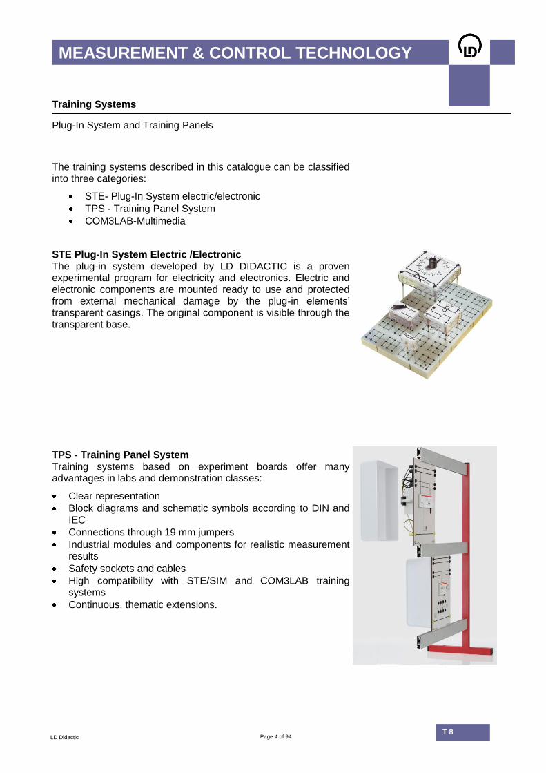
STE Plug-In System Electric /Electronic The plug-in system developed by LD DIDACTIC is a proven experimental program for electricity and electronics. Electric and electronic components are mounted ready to use and protected from external mechanical damage by the plug-in elements’ transparent casings. The original component is visible through the transparent base.
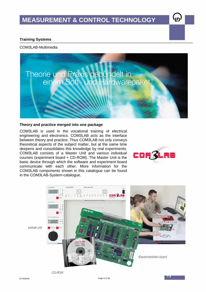
TPS - Training Panel System Training systems based on experiment boards offer many advantages in labs and demonstration classes:
Clear representation
Block diagrams and schematic symbols according to DIN and IEC
Connections through 19 mm jumpers
Industrial modules and components for realistic measurement results
Safety sockets and cables
High compatibility with STE/SIM and COM3LAB training systems
Continuous, thematic extensions.
Page 5 of 94 T 8.2
MEASUREMENT & CONTROL TECHNOLOGY
LD Didactic T 8
Training Systems
COM3LAB-Multimedia
Theory and practice merged into one package
COM3LAB is used in the vocational training of electrical engineering and electronics. COM3LAB acts as the interface between theory and practice. Thus COM3LAB not only conveys theoretical aspects of the subject matter, but at the same time deepens and consolidates this knowledge by real experiments. COM3LAB consists of a Master Unit and various individual courses (experiment board + CD-ROM). The Master Unit is the basic device through which the software and experiment board communicate with each other. More information for the COM3LAB components shown in this catalogue can be found in the COM3LAB-System-catalogue.

Page 6 of 94 T 8.2
MEASUREMENT & CONTROL TECHNOLOGY
LD Didactic T 8
Technical Details
News from the Control Technology
The LD training equipment for measurement and control technology has been completely redesigned. Newly developed and updated electronic devices are based on state of the art technology. Modern low-offset and low-drift components deliver precise results. Digital components with incremental transducers facilitate the adjustment of devices. This allows more time for experimenting, as time-consuming calibrations are rendered unnecessary. The consistent integration of Profi-CASSY and the use of CASSY Lab 2 Software simplify the execution and analysis of experiments. Complex calibrations on links and controllers, and their resulting imprecision are things of the past. All manuals in this catalogue are available in electronic form. Simply click on the example files and Profi-CASSY automatically begins obtaining measurement values.
Many components have digital controls, making parameter adjustments very simple.
Once adjusted, no unwanted parameter changes occur.
Parameter values are always visible during experiments.
Start-up procedures are self-explanatory.

Page 7 of 94 T 8.2
MEASUREMENT & CONTROL TECHNOLOGY
LD Didactic T 8
Technical Details
Components with Incremental Transducers
Digital Controlled System (734 091) Proportional controlled system, time-delayed up to 2nd order integrating or double-integrating
Dead time element (734 0891) Element with proportional behaviour and adjustable dead time (max. 1 s). Ideal for recording frequency response curves.
Two position controller (734 011) A classical controller for slow controlled systems, e.g., temperature controls.
2nd Order transfer element (734 0951) A 2nd order oscillating system. Frequency and attenuation are adjustable.

Page 8 of 94 T 8.2
MEASUREMENT & CONTROL TECHNOLOGY
LD Didactic T 8
Technical Details
CASSY-Interfaces and CASSY Lab 2
The CASSY family consists of various hardware components and the dedicated software package CASSY Lab 2.
CASSY Lab 2 CASSY Lab 2 is a modern 32-bit software, applicable for Windows XP/Vista/7 with the following features:
Data recording
Multimeter
Oscilloscope
XY-plotter
FFT-analysis
Variety of evaluation aids
Export of measurement data and diagrams.

Page 9 of 94 T 8.2
MEASUREMENT & CONTROL TECHNOLOGY
LD Didactic T 8
Technical Details
CASSY-Interfaces and CASSY Lab 2
524 013 Sensor-CASSY 2 Sensor-CASSY is a cascadeable interface for data recording. It has galvanic separated inputs and automatic sensor box recognition by CASSY Lab 2 (plug and play). Sensor-CASSY 2 is the interface with enhanced measurement ranges for:
T 8.1 Measurement Technology
T 8.3 Industrial Control Technology.
524 016 Profi-CASSY The interface with analogue inputs and outputs for control technology applications:
T 8.2 Control Technology
T 8.3 Industrial Control Technology
Profi-CASSY is the interface for specific use in control technology and automation. Equipped with USB and PROFIBUS interfaces, Profi-CASSY can be connected to a network. With two analogue and 16 digital inputs and outputs as well as the PROFIBUS interface, it is incredibly versatile. Profi-CASSY is ideal for integration in PLC, COM3LAB, mechatronics or frequency converters. Profi-CASSY operates under different
application programs, e.g. WinFACT or CASSY Lab 2 .

Page 10 of 94 T 8.2
MEASUREMENT & CONTROL TECHNOLOGY
LD Didactic T 8
Page 11 of 94 T 8.2
MEASUREMENT & SENSOR TECHNOLOGY
LD Didactic T 8
T 8.1 Measurement and Sensor Technology

Page 12 of 94 T 8.2
MEASUREMENT & SENSOR TECHNOLOGY
LD Didactic T 8
T 8.1 Measurement and Sensor Technology
Content
T 8.1.1
T 8.1.3
COM3LAB-Multimedia: Measurement Technology
T 8.1.2
Measuring Nonelectrical Quantities
Measuring Electrical Quantities

Page 13 of 94 T 8.2
MEASUREMENT & SENSOR TECHNOLOGY
LD Didactic T 8
T 8.1 Measurement & Sensor Technology
Classification
Instrumentation, Control and Automation is an interdisciplinary field very prevalent in modern industrial society. Therefore, industry and transport management requires knowledge of energy, mass and traffic flows in production and logistics. The world is becoming more densely populated and requires intelligent processes for controlling and distributing its resources. Sensors are indispensable, as they deliver the data required for controlling processes.
T 8.1.1 Measuring Electrical Quantities The influence of passive components on current and voltage can be demonstrated simply by exchanging plug-in elements (STE). With STE, circuits can be modified and tested according to personal preference.
T 8.1.2 Measuring Nonelectrical Quantities Force and temperature are well-known examples of nonelectrical quantities that should be converted using electric controllers or controls for further processing. Training systems in this group work mainly with experiment boards (TPS). Industrial sensors are used to recognise packaged goods, and the internal structure of sensors remains hidden from the user. This is accomplished by optimising sensors in each individual application.
T 8.1.3 COM3LAB-Multimedia: Measurement Technology In the condensed version of the LD Multimedia training course, principles of measuring elementary electrical and nonelectrical quantities are studied. A special COM3LAB course (700 84) is dedicated to the important topic of Sensor Technology. This course focuses on measurement of nonelectrical quantities.

Page 14 of 94 T 8.2
MEASUREMENT & SENSOR TECHNOLOGY
LD Didactic T 8
T 8.1.1 Measuring Electrical Quantities
Experimental set-up with the proven Plug-In System electric/electronic.
Topics
DC and AC measurements, high impedance sources
Extending measurement ranges
Impedance converter
Instrument amplifiers
Half wave and instrumentation rectifier
F/U and AC converter
Peak value measurement
Exponential voltage and logarithmic voltage measurement.
Page 15 of 94 T 8.2
MEASUREMENT & SENSOR TECHNOLOGY
LD Didactic T 8
T 8.1.1 Measuring Electrical Quantities
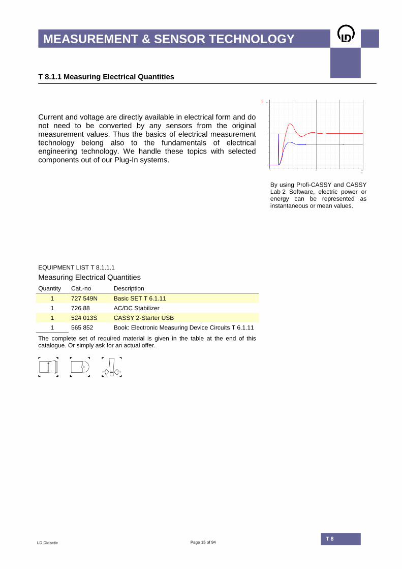
Current and voltage are directly available in electrical form and do not need to be converted by any sensors from the original measurement values. Thus the basics of electrical measurement technology belong also to the fundamentals of electrical engineering technology. We handle these topics with selected components out of our Plug-In systems.
UAV
0
5
10
t / s
0 10 20
By using Profi-CASSY and CASSY Lab 2 Software, electric power or energy can be represented as instantaneous or mean values.
EQUIPMENT LIST T 8.1.1.1
Measuring Electrical Quantities
Quantity Cat.-no Description
1 727 549N Basic SET T 6.1.11
1 726 88 AC/DC Stabilizer
1 524 013S CASSY 2-Starter USB
1 565 852 Book: Electronic Measuring Device Circuits T 6.1.11
The complete set of required material is given in the table at the end of this catalogue. Or simply ask for an actual offer.
Page 16 of 94 T 8.2
MEASUREMENT & SENSOR TECHNOLOGY
LD Didactic T 8
T 8.1.2 Measuring Nonelectrical Quantities
Equipment Sets
T 8.1.2.3
Temperature Measurement
T 8.1.2.2
Recognition of Packaged Goods
T 8.1.2.1
Force Measurements with Strain Gauge

Page 17 of 94 T 8.2
MEASUREMENT & SENSOR TECHNOLOGY
LD Didactic T 8
T 8.1.2 Measuring Nonelectrical Quantities
Equipment Sets
T 8.1.2.1 Force Measurements with Strain Gauge Bridge abutments are monitored with strain gauges. Working with strain gauges in the lab is a very didactic example of how the mechanical quantity, Force, is converted into electrical signals. CASSY Lab 2 creates experiments that are particularly suitable for demonstration using a projector.
Claus Schmidt / pixelio.de
T 8.1.2.2 Recognition of Packaged Goods A practical course based on the use of industrial sensors. Sensors are useful for material recognition and, under the correct circumstances, are able to detect piece goods on conveyor belts.
Martina Braun-Rotmann / pixelio.de
T 8.1.2.3 Temperature Measurement Temperature determines the speed of chemical reactions and influences basic material properties. Physical quantities, such as pressure, concentration, density, pH value, flow rate, etc., depend directly on temperature. As a result, temperature is a very important status parameter in process engineering.
Dieter Schütz / pixelio.de

Page 18 of 94 T 8.2
MEASUREMENT & SENSOR TECHNOLOGY
LD Didactic T 8
T 8.1.2 Measuring Nonelectrical Quantities
T 8.1.2.1 Force Measurements with Strain Gauge
Experimental set-up with bending rods and measurement timer
Topics
Conversion of the mechanical quantity force into electrical signals
Function and calibration of measurement bridges
Measurements per 4-conductor principle.

Page 19 of 94 T 8.2
MEASUREMENT & SENSOR TECHNOLOGY
LD Didactic T 8
T 8.1.2 Measuring Nonelectrical Quantities
T 8.1.2.1 Force Measurements with Strain Gauge
The measurement of force with a strain gauge is a technique used around the world for converting mechanical quantities into electrical signals. Its range of application extends from modern electronic scales in industry and households right up to load controls on building structures and large vehicles. The LD training system investigates the conversion of:
Bending forces
Tension forces and
Torsion stresses.
F
N
0
10
20
30
40
50
m / g
0 1000 2000 3000 4000
Relationship between the loading
mass m (horizontal axis) and the measured weight force F (vertical axis).
EQUIPMENT LIST T 8.1.2.1
Force Measurements with Strain Gauge
Quantity Cat.-no Description
1 734 55 Strain Gauge Transducer
1 734 56 Tensile Test Bar
1 734 565 Torsion Bar
1 311 87 Dial Gauge
1 524 016S2 Profi-CASSY-Starter 2 USB
1 727 66 DC Bridge Amplifier
1 315 36 Set of 7 Weights, 0.1 to 2 kg
The complete set of required material is given in the table at the end of this catalogue. Or simply ask for an actual offer.

Page 20 of 94 T 8.2
MEASUREMENT & SENSOR TECHNOLOGY
LD Didactic T 8
T 8.1.2 Measuring Nonelectrical Quantities
T 8.1.2.2 Recognition of Packaged Goods
Topics
Selection of a suitable sensor according to the material
characteristics of the sample
Alarm circuits with sensors
Structure of a sensor chain for recording various
sample material parameters.
Page 21 of 94 T 8.2
MEASUREMENT & SENSOR TECHNOLOGY
LD Didactic T 8
T 8.1.2 Measuring Nonelectrical Quantities
T 8.1.2.2 Recognition of Packaged Goods
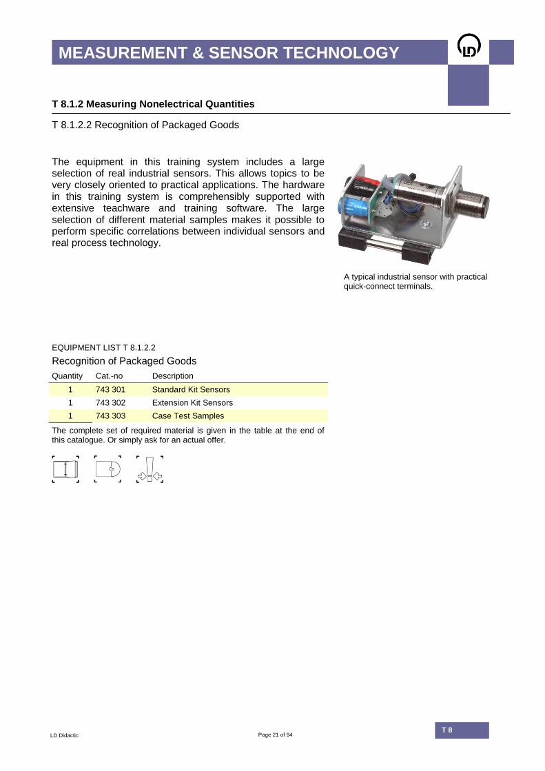
The equipment in this training system includes a large selection of real industrial sensors. This allows topics to be very closely oriented to practical applications. The hardware in this training system is comprehensibly supported with extensive teachware and training software. The large selection of different material samples makes it possible to perform specific correlations between individual sensors and real process technology.
A typical industrial sensor with practical
quick-connect terminals.
EQUIPMENT LIST T 8.1.2.2
Recognition of Packaged Goods
Quantity Cat.-no Description
1 743 301 Standard Kit Sensors
1 743 302 Extension Kit Sensors
1 743 303 Case Test Samples
The complete set of required material is given in the table at the end of this catalogue. Or simply ask for an actual offer.

Page 22 of 94 T 8.2
MEASUREMENT & SENSOR TECHNOLOGY
LD Didactic T 8
T 8.1.2 Measuring Nonelectrical Quantities
T 8.1.2.3 Temperature Measurement
Temperature measurement with various temperature probes.
Topics
Characteristic curve of a temperature-controlled system
Temperature control using an on-off controller
Temperature control using WinFACT
On-off controllers with delayed feedback.
Page 23 of 94 T 8.2
MEASUREMENT & SENSOR TECHNOLOGY
LD Didactic T 8
T 8.1.2 Measuring Nonelectrical Quantities
T 8.1.2.3 Temperature Measurement
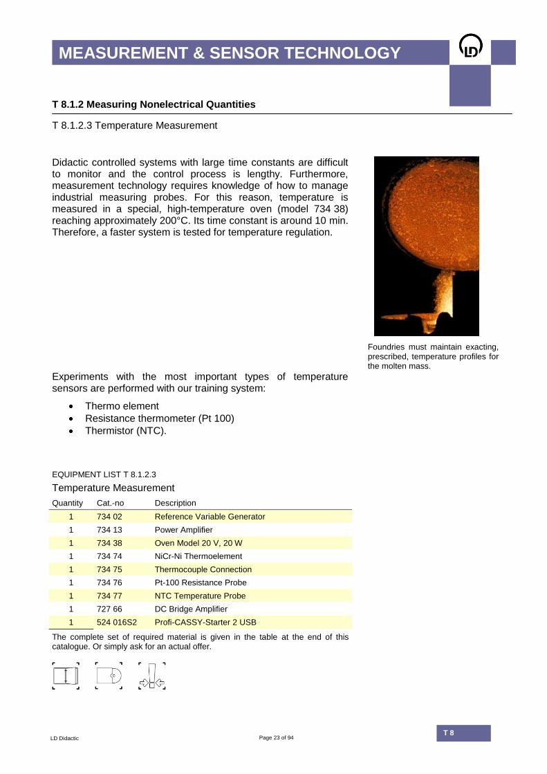
Didactic controlled systems with large time constants are difficult to monitor and the control process is lengthy. Furthermore, measurement technology requires knowledge of how to manage industrial measuring probes. For this reason, temperature is measured in a special, high-temperature oven (model 734 38) reaching approximately 200°C. Its time constant is around 10 min. Therefore, a faster system is tested for temperature regulation.
Foundries must maintain exacting, prescribed, temperature profiles for the molten mass.
Experiments with the most important types of temperature sensors are performed with our training system:
Thermo element
Resistance thermometer (Pt 100)
Thermistor (NTC).
EQUIPMENT LIST T 8.1.2.3
Temperature Measurement
Quantity Cat.-no Description
1 734 02 Reference Variable Generator
1 734 13 Power Amplifier
1 734 38 Oven Model 20 V, 20 W
1 734 74 NiCr-Ni Thermoelement
1 734 75 Thermocouple Connection
1 734 76 Pt-100 Resistance Probe
1 734 77 NTC Temperature Probe
1 727 66 DC Bridge Amplifier
1 524 016S2 Profi-CASSY-Starter 2 USB
The complete set of required material is given in the table at the end of this catalogue. Or simply ask for an actual offer.

Page 24 of 94 T 8.2
MEASUREMENT & SENSOR TECHNOLOGY
LD Didactic T 8
T 8.1.3 COM3LAB-Multimedia: Measurement Technology
Categories (selection)
Electrical Basics
Transformers, Rectifier
Parameters of the AC current
Strength, Pressure, Distance, Speed
Temperature, Brightness.

Page 25 of 94 T 8.2
MEASUREMENT & SENSOR TECHNOLOGY
LD Didactic T 8
T 8.1.3 COM3LAB-Multimedia: Measurement Technology
Measurement Technology with COM3LAB The COM3LAB courses included in this equipment impart the basics laws of electrical engineering as well as measure electrical quantities, such as voltage, current, and resistance. COM3LAB experiments are performed with circuits that have been previously prepared. In each unit, goal-oriented guidance and didactic multimedia simultaneously teach the experiment and its corresponding theory. In COM3LAB course Sensor Technology the measurement of nonelectrical quantities is studied. This course is equipped with many important converters, such as:
Bending beam with strain gauge
Pt-100, NTC, KTY temperature sensors
Peltier elements
Photodiode
Reed contacts
Etc.
COM3LAB courses offer a multi-media education with practical ex-periments. The experimentation circuits are pre-assembled, ready-to-use function modules that make experimentation fast and effective.
EQUIPMENT LIST T 8.1.3
COM3LAB-Multimedia: Measurement Technology
Quantity Cat.-no Description
1 700 11 COM3LAB Course: DC Technology I
1 700 12 COM3LAB Course: DC Technology II
1 700 13 COM3LAB Course: AC Technology I
1 700 14 COM3LAB Course: AC Technology II
1 700 84 COM3LAB-Course: Sensor Technology
1 700 00USB COM3LAB Master Unit (USB)
The complete set of required material is given in the table at the end of this catalogue. Or simply ask for an actual offer. You can find complete information on COM3LAB products in the COM3LAB System Catalogue or online.
Page 26 of 94 T 8.2
MEASUREMENT & SENSOR TECHNOLOGY
LD Didactic T 8

Page 27 of 94 T 8.2
BASICS OF CONTROL TECHNOLOGY
LD Didactic T 8
T 8.2 Basics of Control Technology

Page 28 of 94 T 8.2
BASICS OF CONTROL TECHNOLOGY
LD Didactic T 8
T 8.2 Basics of Control Technology
Content
Control of Technical Lines
T 8.2.1
Fuzzy Control
T 8.2.2
Control of Electronic Lines
T 8.2.3
Modules and Transfer Elements
T 8.2.4
Digital Control
T 8.2.5
Recording of Frequency Responses
T 8.2.6
Stability and Optimization
T 8.2.7
COM3LAB-Multimedia: Control Technology
T 8.2.8

Page 29 of 94 T 8.2
BASICS OF CONTROL TECHNOLOGY
LD Didactic T 8
T 8.2 Basics of Control Technology
Content
T 8.2.1 Control of Technical Lines Technical controlled systems provide non-electrical controlled quantities, such as level, temperature, flow, listing angle, etc., and, consequently, require a sensor system to convert their respective controlled quantities into electrical signals. Experiments with technical control systems are particularly instructional.
T 8.2.2 Fuzzy Control The Fuzzy Control is a rule-based, expert system used to solve control problems without complex mathematics. The control algorithm is created on a PC and accesses the real controlled system through an interface.
T 8.2.3 Control of Electronic Lines Electronic controlled systems require no additional sensors, as only electrical signals are present in the control circuit. Because electrical signals are easy to measure, experiments with electronic control systems are distinguished by conclusive, quantifiable results.
T 8.2.4 Modules and Transfer Elements
In this course, controller and control systems are comprised of basic electronic modules (P, I, D elements) as well as summation points.
T 8.2.5 Digital Control In contrast to a hard-wired hardware controller, here the controller is implemented either as a block-structured or a mathematical model on the computer. Communication with the real environment takes place through an interface.
T 8.2.6 Recording of Frequency Responses Control circuits can be tested in the time domain or in the frequency domain. While transient responses are mainly discussed in the time domain, the Bode diagram, or circle diagram, is relevant to the frequency domain. Practical training for advanced students testing only electronic control systems as measuring objects.
T 8.2.7 Stability and Optimization An optimum control circuit should remain stable when no external influences are present. If a disturbance occurs, the control circuit should quickly return to its initial status without experiencing great deviations from normal operations. The subject can be handled using electronic as well as technical control systems.
T 8.2.8 COM3LAB-Multimedia: Control Technology Two condensed COM3LAB courses comprehensively introduce experimental control technology. In order to understand electronic control circuits, previous knowledge of operational amplifiers and sensor technology is required.

Page 30 of 94 T 8.2
BASICS OF CONTROL TECHNOLOGY
LD Didactic T 8
T 8.2.1 Control of Technical Lines
Equipment Sets
T 8.2.1.5
Brightness Control
T 8.2.1.3
Liquid Level - Measurement and Control
T 8.2.1.7
Listing Control
T 8.2.1.6
Speed and Voltage Control
T 8.2.1.4
Gas Flow Control
T 8.2.1.1
Temperature Control
T 8.2.1.2
Liquid Flow - Measurement and Control
Page 31 of 94 T 8.2
BASICS OF CONTROL TECHNOLOGY
LD Didactic T 8
T 8.2.1 Control of Technical Lines
Equipment Sets
Control of Technical Lines is a focal point in the Fundamentals of Control Technology training system. The subsequent subjects are of great interest in technical training.
T 8.2.1.1 Temperature Control
T 8.2.1.2 Liquid Flow Measurement and Control
T 8.2.1.3 Liquid Level Measurement and Control
T 8.2.1.4 Gas Flow Control
T 8.2.1.5 Brightness Control
T 8.2.1.6 Speed and Voltage Control
T 8.2.1.7 Listing Control.
The speed at which a system responds to status changes is determined by its time constants. Moreover, time constants vary among technical systems. The following is a rough layout:
Temperature: very slow
Fluid flow: slow
Liquid level: slow
Speed: fast
Brightness: very fast

Page 32 of 94 T 8.2
BASICS OF CONTROL TECHNOLOGY
LD Didactic T 8
T 8.2.1 Control of Technical Lines
T 8.2.1.1 Temperature Control
Process visualization (SCADA = Supervisory Control And Data Acquisition). Measurements can be professionally displayed using WinFACT and Profi-CASSY.
Topics
Characteristic curve of temperature controlled systems
Temperature control with two-point controllers
Temperature control using WinFACT
On-off controllers with delayed feedback
Setup of measurement instruments
Calibration of measurement instruments.
Page 33 of 94 T 8.2
BASICS OF CONTROL TECHNOLOGY
LD Didactic T 8
T 8.2.1 Control of Technical Lines
T 8.2.1.1 Temperature Control
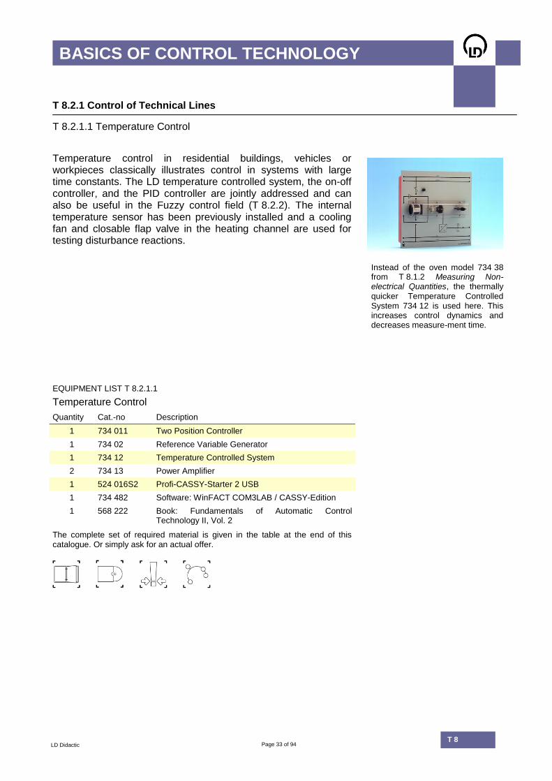
Temperature control in residential buildings, vehicles or workpieces classically illustrates control in systems with large time constants. The LD temperature controlled system, the on-off controller, and the PID controller are jointly addressed and can also be useful in the Fuzzy control field (T 8.2.2). The internal temperature sensor has been previously installed and a cooling fan and closable flap valve in the heating channel are used for testing disturbance reactions.
Instead of the oven model 734 38
from T 8.1.2 Measuring Non-electrical Quantities, the thermally quicker Temperature Controlled System 734 12 is used here. This increases control dynamics and decreases measure-ment time.
EQUIPMENT LIST T 8.2.1.1
Temperature Control
Quantity Cat.-no Description
1 734 011 Two Position Controller
1 734 02 Reference Variable Generator
1 734 12 Temperature Controlled System
2 734 13 Power Amplifier
1 524 016S2 Profi-CASSY-Starter 2 USB
1 734 482 Software: WinFACT COM3LAB / CASSY-Edition
1 568 222 Book: Fundamentals of Automatic Control Technology II, Vol. 2
The complete set of required material is given in the table at the end of this catalogue. Or simply ask for an actual offer.

Page 34 of 94 T 8.2
BASICS OF CONTROL TECHNOLOGY
LD Didactic T 8
T 8.2.1 Control of Technical Lines
T 8.2.1.2 Liquid Flow - Measurement and Control
Level and flow measurement and control can be tested together within fluid controlled systems.
Topics
Step response of flow controlled systems
Fluid flow control with the PID Controller
Fluid flow control with WinFACT.

Page 35 of 94 T 8.2
BASICS OF CONTROL TECHNOLOGY
LD Didactic T 8
T 8.2.1 Control of Technical Lines
T 8.2.1.2 Liquid Flow - Measurement and Control
As is the case in petrochemistry or water management, level and flow are integral to motor vehicle technology and fundamental to production and logistics within industrial applications. Fluid throughput should be recorded, controlled and corrected at every stage: from tankers, through refineries, up through the clarification plant.
UAV
0
5
10
t / s
0 10 20
The liquid flow is measured with an
internal sensor. Both absolute and relative reading flow meters can be created using CASSY Lab 2 software. Red: Flow measured in Closed
Loop Mode (using integrated subordinate control system) Black: Open Loop
EQUIPMENT LIST T 8.2.1.2
Liquid Flow - Measurement and Control
Quantity Cat.-no Description
1 734 02 Reference Variable Generator
1 734 064 PID Digital Controller
1 734 262 Liquid Controlled System
1 524 016S2 Profi-CASSY-Starter 2 USB
1 734 482 Software: WinFACT COM3LAB / CASSY-Edition
1 564 24EN Book: Control of Technical Lines
The complete set of required material is given in the table at the end of this catalogue. Or simply ask for an actual offer.
Page 36 of 94 T 8.2
BASICS OF CONTROL TECHNOLOGY
LD Didactic T 8
T 8.2.1 Control of Technical Lines
T 8.2.1.3 Liquid Level - Measurement and Control
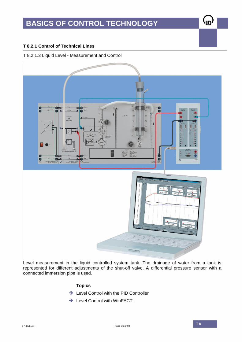
Level measurement in the liquid controlled system tank. The drainage of water from a tank is represented for different adjustments of the shut-off valve. A differential pressure sensor with a connected immersion pipe is used.
Topics
Level Control with the PID Controller
Level Control with WinFACT.

Page 37 of 94 T 8.2
BASICS OF CONTROL TECHNOLOGY
LD Didactic T 8
T 8.2.1 Control of Technical Lines
T 8.2.1.3 Liquid Level - Measurement and Control
In addition to pressure measurement, temperature, flow, and the acquisition of filling levels in tanks and containers play a key role in the chemical industry. Different methods are used to measure filling levels. The LD training system uses the following probes:
Capacitive
Immersion pipe with differential pressure sensor
Level switch with float
w
V
-10
-9
-8
-7
-6
-5
-4
-3
-2
-1
0
1
2
3
4
5
6
7
8
9
t / s
5 10 15 20
x
V
-10
-9
-8
-7
-6
-5
-4
-3
-2
-1
0
1
2
3
4
5
6
7
8
9
External sensors are required in
order to detect the liquid level and support a preselected level within the control circuit.
EQUIPMENT LIST T 8.2.1.3 – SUPPLEMENTARY TO T 8.2.1.2
Liquid Level - Measurement and Control
Quantity Cat.-no Description
1 734 81 Differential Pressure Transducer
1 734 876 Immersion Tube
1 564 24EN Book: Control of Technical Lines
The basic experiment can be extended for the dual tank model. The probes listed below can also be used in the basic experiment
OPTION
Liquid Level Control on a Dual Tank Model
Quantity Cat.-no Description
1 734 264 Additional Reservoir
1 727 68 C/F-, L/F- and F/U-Converter
1 734 861 Capacitive Bar-Type Probe
1 734 881 Level Switch with Float
1 734 89 Capacitive Level Switch
1 568 24EN Book: Control of Technical Lines
The complete set of required material is given in the table at the end of this catalogue. Or simply ask for an actual offer.
Page 38 of 94 T 8.2
BASICS OF CONTROL TECHNOLOGY
LD Didactic T 8
T 8.2.1 Control of Technical Lines
T 8.2.1.4 Gas Flow Control
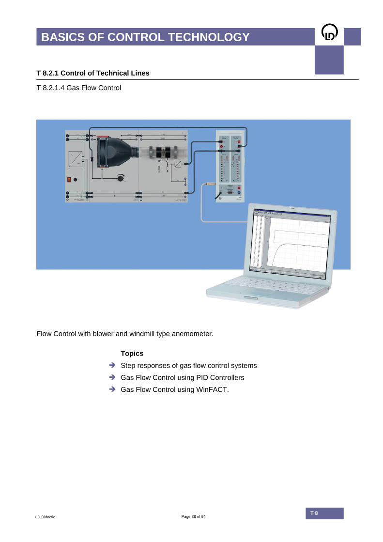
Flow Control with blower and windmill type anemometer.
Topics
Step responses of gas flow control systems
Gas Flow Control using PID Controllers
Gas Flow Control using WinFACT.

Page 39 of 94 T 8.2
BASICS OF CONTROL TECHNOLOGY
LD Didactic T 8
T 8.2.1 Control of Technical Lines
T 8.2.1.4 Gas Flow Control
In classical control circuits, gas flow is measured and maintained at the desired value. The anemometer operates using thermal cross or thermosensors. Applications for gas flow controls include:
Aeronautics
Motor vehicles
Air conditioning.
UAV
0
5
10
t / s
0 10 20
The static characteristic curve
of a thermal anemometer is represented in the experiment. The air flow rate is measured.
The exploitation of wind energy creates a greater demand for technology which measures and controls flowing gasses. Varying wind speeds should be registered and converted into an optimum blade adjustment for the propeller (pitch control). If maximum energy production is to be achieved, the nacelle must be turned into the wind at all times.
Bigmama / pixelio.de
EQUIPMENT LIST T 8.2.1.4
Gas Flow Control
Quantity Cat.-no Description
1 666 630 Blower
1 666 632 Windmill Type Anemometer
1 734 02 Reference Variable Generator
1 734 064 PID Digital Controller
1 524 016S2 Profi-CASSY-Starter 2 USB
1 734 482 Software: WinFACT COM3LAB / CASSY-Edition
1 564 24EN Book: Control of Technical Lines
(): recommended
The complete set of required material is given in the table at the end of this catalogue. Or simply ask for an actual offer.

Page 40 of 94 T 8.2
BASICS OF CONTROL TECHNOLOGY
LD Didactic T 8
T 8.2.1 Control of Technical Lines
T 8.2.1.5 Brightness Control
Topics
Step responses of light controlled systems
Brightness Control with PID Controller
Brightness Control with WinFACT.

Page 41 of 94 T 8.2
BASICS OF CONTROL TECHNOLOGY
LD Didactic T 8
T 8.2.1 Control of Technical Lines
T 8.2.1.5 Brightness Control
Brightness control is a practical example of how fast systems are controlled. Control circuits responding to changes in brightness can be found within biological systems, sports halls, hospitals, cameras, etc. Experiments operate using newly developed controlled systems with extremely short time constants. Responses to starting point changes and disturbance reactions are tested.
Light controlled system 734 311 contains effective light source, interfering light source and light sensor. New electronic system with superbright LED.
EQUIPMENT LIST T 8.2.1.5
Brightness Control
Quantity Cat.-no Description
1 734 02 Reference Variable Generator
1 734 064 PID Digital Controller
1 734 311 Light Controlled System
1 524 016S2 Profi-CASSY-Starter 2 USB
1 734 482 Software: WinFACT COM3LAB / CASSY-Edition
1 568 222 Book: Fundamentals of Automatic Control Technology II, Vol. 2
The complete set of required material is given in the table at the end of this catalogue. Or simply ask for an actual offer.
Page 42 of 94 T 8.2
BASICS OF CONTROL TECHNOLOGY
LD Didactic T 8
T 8.2.1 Technical Systems
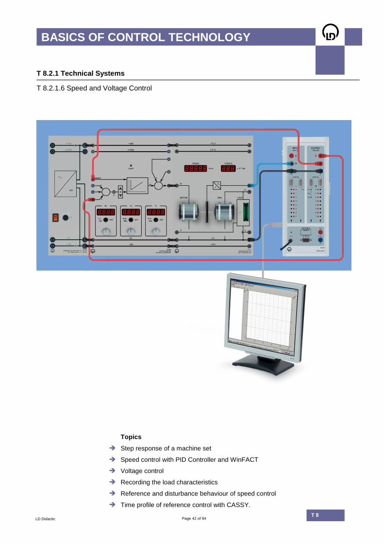
T 8.2.1.6 Speed and Voltage Control
Topics
Step response of a machine set
Speed control with PID Controller and WinFACT
Voltage control
Recording the load characteristics
Reference and disturbance behaviour of speed control
Time profile of reference control with CASSY.

Page 43 of 94 T 8.2
BASICS OF CONTROL TECHNOLOGY
LD Didactic T 8
T 8.2.1 Technical Systems
T 8.2.1.6 Speed and Voltage Control
The set of machines 10 W is a technical controlled system for experiments on speed and voltage control. It consists of an electrical drive including digital speed sensing, a generator machine and an electronic load. Using the adjustable load, real generator operation can be investigated. The machine set makes it possible to measure the load characteristic of the generator and the dynamic behaviour of systems of higher order. A microprocessor controlled power module supplies the drive machine. Thus no external power amplifier is required. The set of machines comes with 7-segment displays for the measurement of speed and torque.
n*
rpm
0
1000
2000
3000
t / s
0 10 20 30 40 50 60
Optimum speed control Black: Reference Red: Controlled variable
UA1
V
1
1,5
2
2,5
3
3,5
4
4,5
5
5,5
6
6,5
7
t / s
3 3,5 4 4,5
UX
V
1
1,5
2
2,5
3
3,5
4
4,5
5
5,5
6
6,5
7
t1 = 0,101 s, t2 = 0,703 s T1=0.40, T2=0.10
Dynamic behaviour of the machine set
EQUIPMENT LIST T 8.2.1.6
Speed and Voltage Control
Quantity Cat.-no Description
1 734 02 Reference Variable Generator
1 734 064 PID Digital Controller
1 734 111 Set of Machines 10 W
1 524 016S2 Profi-CASSY-Starter 2 USB
1 564 24EN Book: Control of Technical Lines
1 734 482 Software: WinFACT COM3LAB / CASSY-Edition
The complete set of required material is given in the table at the end of this catalogue. Or simply ask for an actual offer.

Page 44 of 94 T 8.2
BASICS OF CONTROL TECHNOLOGY
LD Didactic T 8
T 8.2.1 Control of Technical Lines
T 8.2.1.7 Listing Control
Topics
Position control using PID controllers
Position control using WinFACT.

Page 45 of 94 T 8.2
BASICS OF CONTROL TECHNOLOGY
LD Didactic T 8
T 8.2.1 Control of Technical Lines
T 8.2.1.7 Listing Control
Listing, or heeling, is the term given to the rolling movement of ships in waves or during the loading procedure. Listing occurs particularly when a heavy freight train mounts a ferry. When rail vehicles mount a ferry, there should be no rail kinks at the interface between ferry and feeder. Such control problems – all of which pertain to attitude stabilisation – can be investigated using listing controls. The system can be similarly operated using the real PID Digital Controller (734 064) or with a software controller based on WinFACT.
Listing controllers ensure a
balanced course tracking.
EQUIPMENT LIST T 8.2.1.7
Listing Control
Quantity Cat.-no Description
1 734 02 Reference Variable Generator
1 734 300 Listing Controlled System
1 734 064 PID Digital Controller
1 524 016S2 Profi-CASSY-Starter 2 USB
1 564 24EN Book: Control of Technical Lines
1 734 482 Software: WinFACT COM3LAB / CASSY-Edition
The complete set of required material is given in the table at the end of this catalogue. Or simply ask for an actual offer.

Page 46 of 94 T 8.2
BASICS OF CONTROL TECHNOLOGY
LD Didactic T 8
Software
WinFACT
WinFACT is an industry-oriented software used to analyze, synthesize, and simulate conventional control systems as well as to manage FUZZY and neuro systems. In addition, WinFACT is used for process visualisation (SCADA). The software has a modular structure and allows real control circuits to be modelled. In the adjacent image depicting speed control of an electric machine, the simulated WinFACT control circuit works with a PID controller (red lines). Parallel to the simulated control circuit, there is a second, identically parameterised PID controller with Profi-CASSY as the interface. The actual machine set is connected to the Profi-CASSY (blue lines). The controlled quantities of actual and simulated controlled systems are plotted and printed together with the reference quantity (black lines).
Other technical or electronic control systems from this catalogue can also be modelled with the help of WinFACT. The better the real process is understood, the closer will be the correspondence between simulated and real results.
0 2 4 6 8 10 12 14 16 18 20
t ->
-12
-10
-8
-6
-4
-2
0
2
4
6
8
10
y->
GENERATORMOTORDrive
The LD Didactic scope of supply contains the following software packages for experimental control technology:
When the model for the control system is built correctly, the real experiment and the simulation produce the same control quantity curve (speed). In addition, for optimum control adjustment, deviation from the desired speed (blue curve) should be as low as possible in both cases.
SOFTWARE PACKAGES
WinFACT
Cat.no Description Contents
734 482 WinFACT COM3LAB / CASSY-Edition BORIS 10 Blocks, time period
734 492 WinFACT7 LD Licence BORIS 100 Blocks, time period Fuzzy, Optimization
Page 47 of 94 T 8.2
BASICS OF CONTROL TECHNOLOGY
LD Didactic T 8
Software
WinFACT / CASSY Lab 2
The COM3LAB/CASSY-Edition is a reduced, single-user license. It must be purchased separately for each workstation. Control circuits with a maximum of 10 block elements can be built using the COM3LAB/CASSY-Edition. Fuzzy and Optimisation are not included. The extensive package, WinFACT LD-Licence, allows concurrent use in up to 10 workstations. Apart from measurement, simulation, and representation in time domain, this licence contains a Fuzzy-Shell for building rule-based control circuits and optimisation modules. The LD Driver for COM3LAB and CASSY as well as the experimentation examples for WinFACT are included exclusively in both software packages.
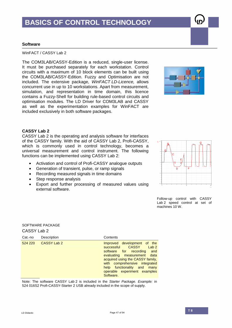
CASSY Lab 2 CASSY Lab 2 is the operating and analysis software for interfaces of the CASSY family. With the aid of CASSY Lab 2, Profi-CASSY, which is commonly used in control technology, becomes a universal measurement and control instrument. The following functions can be implemented using CASSY Lab 2:
Activation and control of Profi-CASSY analogue outputs
Generation of transient, pulse, or ramp signals
Recording measured signals in time domains
Step response analysis
Export and further processing of measured values using external software.
UY
V
-10
-5
0
5
10
t / s
0 50 100
A
B
C
1
D
E
2
F
G
Follow-up control with CASSY Lab 2 speed control at set of machines 10 W.
SOFTWARE PACKAGE
CASSY Lab 2
Cat.-no Description Contents
524 220 CASSY Lab 2 Improved development of the successful CASSY Lab 2 software for recording and evaluating measurement data acquired using the CASSY family, with comprehensive integrated help functionality and many operable experiment examples Software.
Note: The software CASSY Lab 2 is included in the Starter Package. Example: in 524 016S2 Profi-CASSY-Starter 2 USB already included in the scope of supply.

Page 48 of 94 T 8.2
BASICS OF CONTROL TECHNOLOGY
LD Didactic T 8
T 8.2.2 Fuzzy Control
Air conditioners using Fuzzy control. Controlled systems can be heated electrically using halogen lamps and cooled by fans.
Topics
Conceptual Fuzzy controller design
Definition of Fuzzy Sets
Establishing linguistic rules
Linear and non-linear Fuzzy controllers
Fuzzy heating and climate control
Speed control using Fuzzy
Expert systems.

Page 49 of 94 T 8.2
BASICS OF CONTROL TECHNOLOGY
LD Didactic T 8
T 8.2.2 Fuzzy Control
Rule-based control algorithms Fuzzy describes a formula for controlling technical systems using almost no mathematics. The control strategy is defined in layman’s terms. Fuzzy control is particularly useful for systems with many controlled quantities and can be used with a variety of everyday devices, ranging from washing machines to digital cameras. Three examples are presented in this practical training:
Heating and climate
Speed Control
Position control
0 10 20 30 40 50 60 70
t ->
0
1
2
3
4
5
6
7
8
9
y -
>
Reference ValueInput from processFC
P-Fuzzy and PI-Fuzzy controllers are built for linear and non-linear controllers.
Curves for controlled quantity, control quantity, and reference quantity in a speed control system.
EQUIPMENT LIST T 8.2.2
Fuzzy Control
Quantity Cat.-no. Description
1 734 02 Reference Variable Generator
1 734 111 Set of Machines 10 W
1 734 12 Temperature Control System
2 734 13 Power Amplifier
1 734 300 Listing Controlled System
1 524 016S2 Profi-CASSY-Starter 2 USB
1 568 222 Book: Fundamentals of Automatic Control Technology II, Vol. 2
1 734 492 Software: WinFACT7 LD Licence (English)
The complete set of required material is given in the table at the end of this catalogue. Or simply ask for an actual offer.

Page 50 of 94 T 8.2
BASICS OF CONTROL TECHNOLOGY
LD Didactic T 8
T 8.2.2 Fuzzy Control
Fuzzy Applications
Listing Controlled System Set of machines 10 W Temperature Control System Fuzzy is also used in automotive engineering. After speed changes, Drive by Wire technology transmits the desires of the driver to a Fuzzy controller.
Two-point control with Fuzzy
0 50 100 150 200 250 300
t
0
2
4
6
8
10
12
x
Regelgröße
StellgrößeTeilexperiment 1

Page 51 of 94 T 8.2
BASICS OF CONTROL TECHNOLOGY
LD Didactic T 8
T 8.2.2 Fuzzy Control
Inside a Fuzzy controller
The Fuzzy PI controller with Profi-CASSY interface is built using the BORIS WinFACT module.
MAX-MIN
Schwerpunkt
StaTemp
DynTemp
Boiler
Structure of the PI-Fuzzy controller: The input variables are the Fuzzy Sets StaTemp and DynTemp. Boiler is the output variable.
Boiler
StaticTempDynTemp
1
0
-1
1
-1
1
3D characteristic field of the Fuzzy climate control. Input and output quantities are plotted on the axes.
0.0 0.1 0.2 0.3 0.4 0.5 0.6 0.7 0.8 0.9 1.0
0.0
0.2
0.4
0.6
0.8
1.0
1.2
BoilerVerySmallSmallMediumBigVeryBig
The linguistic output variable, Boiler, contains the following Fuzzy Sets:
VerySmall
Small
Medium
Big
VeryBig

Page 52 of 94 T 8.2
BASICS OF CONTROL TECHNOLOGY
LD Didactic T 8
T 8.2.3 Control of Electronic Lines
Basic Set
Topics
Continuous, discontinuous and quasi-continuous control
Recording and analysing step responses
Feedback within transmission systems
Output quantities of an open-loop control
Control systems with start time and dead time
Testing responses to set point changes and disturbance reactions.

Page 53 of 94 T 8.2
BASICS OF CONTROL TECHNOLOGY
LD Didactic T 8
T 8.2.3 Control of Electronic Lines
Basic Set
The equipment allows experiments ranging from fundamental to university levels. Classic transfer elements of control technology are examined in the time domain. Digital controls for controller parameters along with time constants allow simple, user-friendly and precise device operation. Both continued and discontinued controller versions are available. The CASSY Interface allows computer assisted control and analysis. For university applications, additional simulation using WinFACT is recommended.
The front panels show the standard international block diagrams.
EQUIPMENT LIST T 8.2.3
Control of Electronic Lines
Quantity Cat.-no Description
1 734 011 Two Position Controller
1 734 02 Reference Variable Generator
1 734 064 PID Digital Controller
1 734 0891 Dead Time Element
2 734 091 Digital Controlled System
1 734 0951 2nd Order Transfer Element
1 524 016S2 Profi-CASSY-Starter 2 USB
1 734 482 Software: WinFACT COM3LAB / CASSY-Edition
1 564 19EN Book: Control of Electronic Lines
The complete set of required material is given in the table at the end of this catalogue. Or simply ask for an actual offer.

Page 54 of 94 T 8.2
BASICS OF CONTROL TECHNOLOGY
LD Didactic T 8
T 8.2.4 Modules and Transfer Elements
Supplementary Set
PI controller built from discrete function blocks
Topics
Manual adjustment of system parameters Kp, Ki, Kd
Measurement scales for instruments
Recording and analysing step responses
Modular PI and PID controller assembly
Quasi-continuous control of a 2nd order system.

Page 55 of 94 T 8.2
BASICS OF CONTROL TECHNOLOGY
LD Didactic T 8
T 8.2.4 Modules and Transfer elements
Supplementary Set
With this supplementary course, controller or control systems are comprised of basic electronic modules (P, I, D elements) as well as summation points. This offers greater flexibility in experiment design. Many experiments within Electronic controlled systems T 8.2.3 can be reproduced in detail using the modules. There are also additional interesting experiments, such as quasi-continuous control of 2nd order systems. Here, the discontinuous controller adopts a quasi-continuous controller response using feedbacks.
UAV
0
5
10
t / s
0 10 20
Step responses of different transfer
elements and controlled systems are recorded with CASSY Lab 2.
EQUIPMENT LIST T 8.2.4 – SUPPLEMENTARY TO T 8.2.3
Modules and Transfer Elements
Quantity Cat.-no. Description
1 734 03 P Controller
1 734 04 Integral-Action Element
1 734 05 Derivative-Action Element
1 734 07 Summing point, 2 Inputs
1 734 08 Summing point, 5 Inputs
The complete set of required material is given in the table at the end of this catalogue. Or simply ask for an actual offer.
Page 56 of 94 T 8.2
BASICS OF CONTROL TECHNOLOGY
LD Didactic T 8
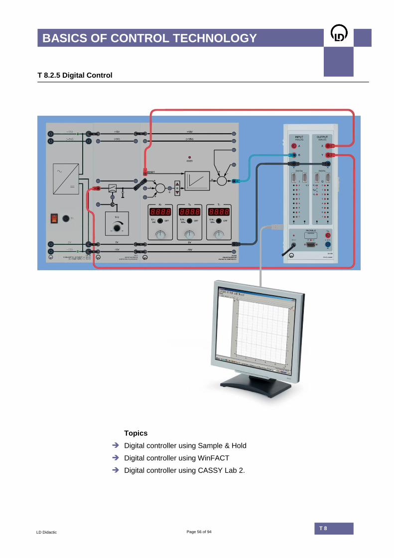
T 8.2.5 Digital Control
Topics
Digital controller using Sample & Hold
Digital controller using WinFACT
Digital controller using CASSY Lab 2.
Page 57 of 94 T 8.2
BASICS OF CONTROL TECHNOLOGY
LD Didactic T 8
T 8.2.5 Digital Control
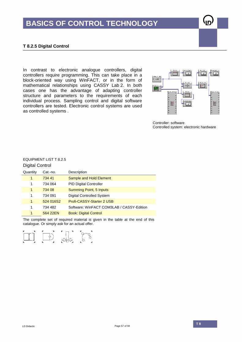
In contrast to electronic analogue controllers, digital controllers require programming. This can take place in a block-oriented way using WinFACT, or in the form of mathematical relationships using CASSY Lab 2. In both cases one has the advantage of adapting controller structure and parameters to the requirements of each individual process. Sampling control and digital software controllers are tested. Electronic control systems are used as controlled systems .
Controller: software Controlled system: electronic hardware
EQUIPMENT LIST T 8.2.5
Digital Control
Quantity Cat.-no. Description
1 734 41 Sample and Hold Element
1 734 064 PID Digital Controller
1 734 08 Summing Point, 5 Inputs
1 734 091 Digital Controlled System
1 524 016S2 Profi-CASSY-Starter 2 USB
1 734 482 Software: WinFACT COM3LAB / CASSY-Edition
1 564 22EN Book: Digital Control
The complete set of required material is given in the table at the end of this catalogue. Or simply ask for an actual offer.
Page 58 of 94 T 8.2
BASICS OF CONTROL TECHNOLOGY
LD Didactic T 8
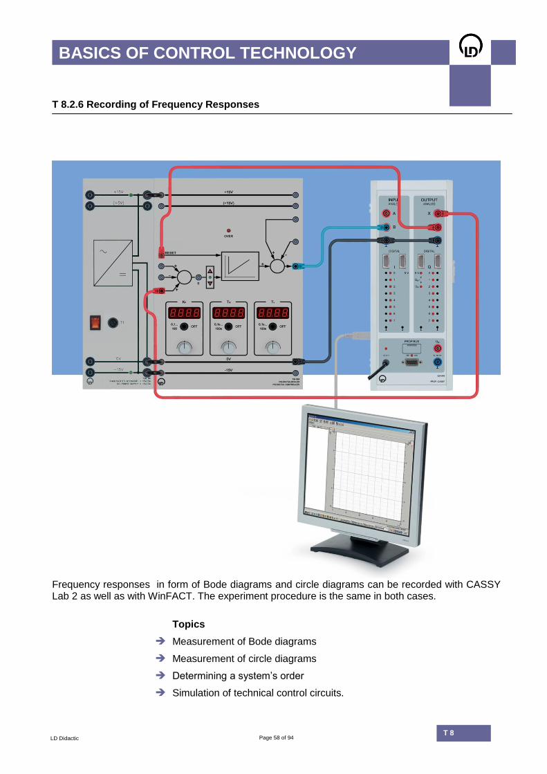
T 8.2.6 Recording of Frequency Responses
Frequency responses in form of Bode diagrams and circle diagrams can be recorded with CASSY Lab 2 as well as with WinFACT. The experiment procedure is the same in both cases.
Topics
Measurement of Bode diagrams
Measurement of circle diagrams
Determining a system’s order
Simulation of technical control circuits.

Page 59 of 94 T 8.2
BASICS OF CONTROL TECHNOLOGY
LD Didactic T 8
T 8.2.6 Recording of Frequency Responses
The measurements show the Nyquist plot and Bode diagram of a PT2 element, both plotted using CASSY Lab 2. The PT2 element consists of two PT1 elements connected in series.
CASSY Lab 2 provides graphing tools to analyse amplitude response curves. It is possible, among other things, to determine the slope of the curve. For PT2 elements, this measuring function results in an attenuation increase of 40 dB per decade of frequency.
ATF
0,1
1
f / Hz
0,1 1 10
EQUIPMENT LIST T 8.2.6
Recording of Frequency Responses
Quantity Cat.-no. Description
1 734 064 PID Digital Controller
1 734 0891 Dead Time Element
1 734 091 Digital Controlled System
1 734 0951 2nd Order Transfer Element
1 524 016S2 Profi-CASSY-Starter 2 USB
1 564 20EN Book: Recording of Frequency Responses
The complete set of required material is given in the table at the end of this catalogue. Or simply ask for an actual offer.

Page 60 of 94 T 8.2
BASICS OF CONTROL TECHNOLOGY
LD Didactic T 8
T 8.2.7 Stability and Optimisation
Topics
Controller settings for a controlled system with dead time
Stability testing of a 3rd order control system
Simulation of technical lines
Stability tests with Nyquist plots
Criteria for system optimisation
Controller optimisation according to integral criteria
Controller optimisation according to adjustment rules.

Page 61 of 94 T 8.2
BASICS OF CONTROL TECHNOLOGY
LD Didactic T 8
T 8.2.7 Stability and Optimisation
Stability testing and control circuit optimisation are among the most important tasks of control technology. Their results determine the usability of the planned application’s control.
This equipment allows experiments for numerical optimisation of system parameters with the help of evolution strategies. Computer assisted optimisation is tested according to selectable quality criteria (e.g. ITAE, ISE, etc.).
x
V
-10
0
10
t / s
0 10 20 30 40 50
x
V
-10
0
10
Stability test of an electronically
simulated gas flow control. The integral controlled system is governed by a PI controller. Depen-ding on the selected control parameter, the closed loop control becomes unstable.
EQUIPMENT LIST T 8.2.7
Stability and Optimisation
Quantity Cat.-no. Description
1 734 04 Integral-Action Element
1 734 064 PID Digital Controller
1 734 08 Summing Point, 5 Inputs
1 734 0891 Dead Time Element
2 734 091 Digital Controlled System
1 734 0951 2nd Order Transfer Element
1 524 016S2 Profi-CASSY-Starter 2 USB
1 734 492 Software: WinFACT LD Licence
1 564 21EN Book: Stability and Optimisation
The complete set of required material is given in the table at the end of this catalogue. Or simply ask for an actual offer.
Page 62 of 94 T 8.2
BASICS OF CONTROL TECHNOLOGY
LD Didactic T 8
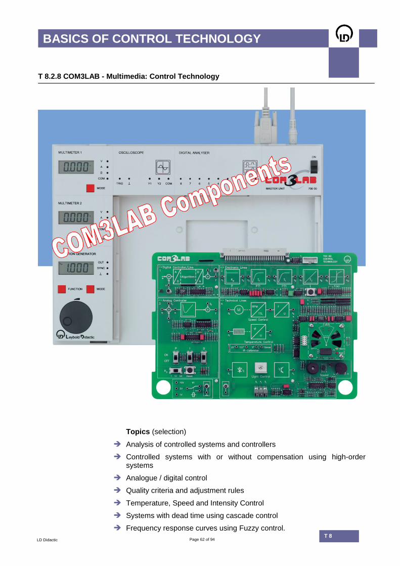
T 8.2.8 COM3LAB - Multimedia: Control Technology
Topics (selection)
Analysis of controlled systems and controllers
Controlled systems with or without compensation using high-order systems
Analogue / digital control
Quality criteria and adjustment rules
Temperature, Speed and Intensity Control
Systems with dead time using cascade control
Frequency response curves using Fuzzy control.
Page 63 of 94 T 8.2
BASICS OF CONTROL TECHNOLOGY
LD Didactic T 8
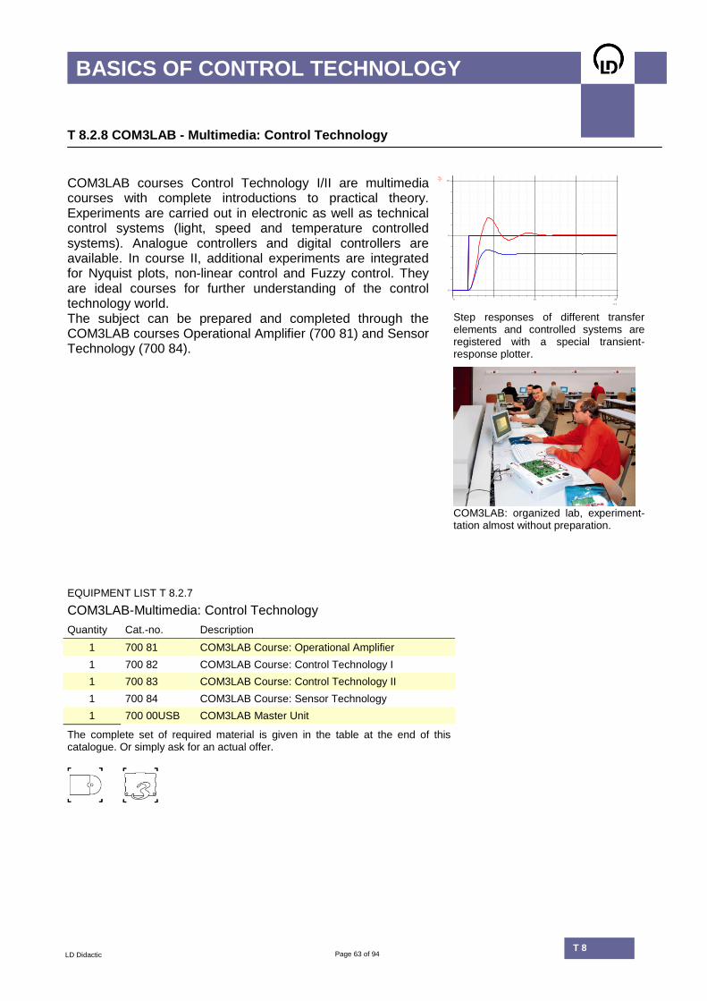
T 8.2.8 COM3LAB - Multimedia: Control Technology
COM3LAB courses Control Technology I/II are multimedia courses with complete introductions to practical theory. Experiments are carried out in electronic as well as technical control systems (light, speed and temperature controlled systems). Analogue controllers and digital controllers are available. In course II, additional experiments are integrated for Nyquist plots, non-linear control and Fuzzy control. They are ideal courses for further understanding of the control technology world.
UAV
0
5
10
t / s
0 10 20
The subject can be prepared and completed through the COM3LAB courses Operational Amplifier (700 81) and Sensor Technology (700 84).
Step responses of different transfer elements and controlled systems are registered with a special transient-response plotter.
COM3LAB: organized lab, experiment-
tation almost without preparation.
EQUIPMENT LIST T 8.2.7
COM3LAB-Multimedia: Control Technology
Quantity Cat.-no. Description
1 700 81 COM3LAB Course: Operational Amplifier
1 700 82 COM3LAB Course: Control Technology I
1 700 83 COM3LAB Course: Control Technology II
1 700 84 COM3LAB Course: Sensor Technology
1 700 00USB COM3LAB Master Unit
The complete set of required material is given in the table at the end of this catalogue. Or simply ask for an actual offer.

Page 64 of 94 T 8.2
BASICS OF CONTROL TECHNOLOGY
LD Didactic T 8

Page 65 of 94 T 8.2
INDUSTRIAL PROCESS CONTROL
LD Didactic T 8.3
T 8.3 Industrial Process Control

Page 66 of 94 T 8.2
INDUSTRIAL PROCESS CONTROL
LD Didactic T 8.3
T 8.3 Industrial Process Control
In the field of industrial control technology using commercial components, LD offers a variety of systems with practical features:
Compact assembly, also suitable for small labs.
Use of commercial components for training with real industrial devices.
Computer analysis for a complete reporting. Compressed air is an easy-to-handle energy source used for training purposes. This is why the industrial control technology from LD works partially with pneumatic components. Pneumatic control technology can be supplementally connected to an industrial controller, e.g. a PLC. In addition, the subject area contains courses pertaining to industrial compact controllers as well as the control of industrial driving machines.
Instrumentation in the industrial control technology can take place on an electric, pneumatic or hydraulic basis. Process-related or security-related reasons, e.g. due to explosion hazard, make it necessary the use of pneumatic devices in many production branches.

Page 67 of 94 T 8.2
INDUSTRIAL PROCESS CONTROL
LD Didactic T 8.3
T 8.3 Industrial Process Control
Pressure measurement with CASSY Pneumatic devices include:
controller
servo units
measuring transducer
Sensor-CASSY and two pressure sensors S are used to measure
pressure. Analysis and reporting take place using the CASSY Lab 2 software.
Pneumatic components work in the standard pressure range from 0.2 bar to 1.0 bar with Live Zero Technology, widespread in industrial applications. This process corresponds with 0.2 bar = 0% and 1.0 bar = 100%. The auxiliary power supply has a standard value of 1.4 bar, equivalent to the voltage supply in electronic devices. A pressure energy line exists with 2 bar (E1) as the process energy flow.
Relationship between absolute and relative pressure using Live Zero.
The pneumatic valves of the following devices are provided with electronic controls for Sensor-CASSY, allowing simple experiment procedures. Thanks to this system, pressure jumps or load variations can be easily and precisely controlled by the computer.
Process control with CASSY

Page 68 of 94 T 8.2
INDUSTRIAL PROCESS CONTROL
LD Didactic T 8.3
T 8.3 Industrial Process Control
Equipment Sets
Basics Pneumatic Control
T 8.3.1
Pneumatic Controllers
T 8.3.2
Extended Pneumatic Systems
T 8.3.3
Process with Industrial Control
T 8.3.4
Control with Compact Controllers
T 8.3.5
Control of an Industrial Machine 300 W
T 8.3.6
Heating Control
T 8.3.7
COM3LAB-Multimedia: Electro-Pneumatics
T 8.3.8
Page 69 of 94 T 8.2
INDUSTRIAL PROCESS CONTROL
LD Didactic T 8.3
T 8.3 Industrial Process Control
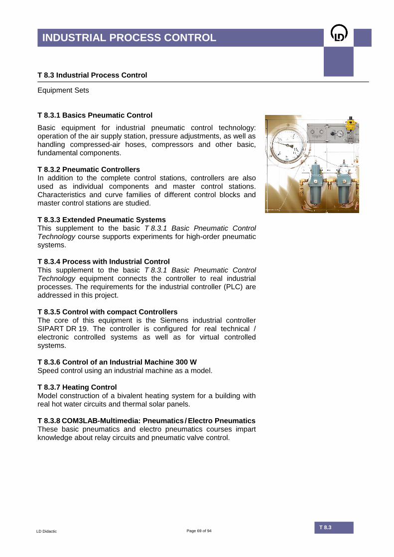
Equipment Sets T 8.3.1 Basics Pneumatic Control
Basic equipment for industrial pneumatic control technology: operation of the air supply station, pressure adjustments, as well as handling compressed-air hoses, compressors and other basic, fundamental components.
T 8.3.2 Pneumatic Controllers In addition to the complete control stations, controllers are also used as individual components and master control stations. Characteristics and curve families of different control blocks and master control stations are studied. T 8.3.3 Extended Pneumatic Systems This supplement to the basic T 8.3.1 Basic Pneumatic Control Technology course supports experiments for high-order pneumatic systems. T 8.3.4 Process with Industrial Control This supplement to the basic T 8.3.1 Basic Pneumatic Control Technology equipment connects the controller to real industrial processes. The requirements for the industrial controller (PLC) are addressed in this project. T 8.3.5 Control with compact Controllers The core of this equipment is the Siemens industrial controller SIPART DR 19. The controller is configured for real technical / electronic controlled systems as well as for virtual controlled systems. T 8.3.6 Control of an Industrial Machine 300 W Speed control using an industrial machine as a model. T 8.3.7 Heating Control Model construction of a bivalent heating system for a building with real hot water circuits and thermal solar panels. T 8.3.8 COM3LAB-Multimedia: Pneumatics / Electro Pneumatics These basic pneumatics and electro pneumatics courses impart knowledge about relay circuits and pneumatic valve control.
Page 70 of 94 T 8.2
INDUSTRIAL PROCESS CONTROL
LD Didactic T 8.3
T 8.3.1 Basics Pneumatic Control
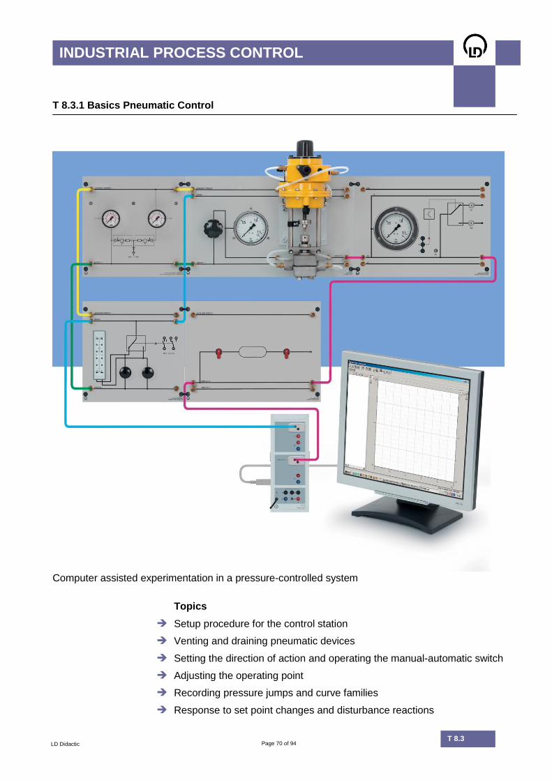
Computer assisted experimentation in a pressure-controlled system
Topics
Setup procedure for the control station
Venting and draining pneumatic devices
Setting the direction of action and operating the manual-automatic switch
Adjusting the operating point
Recording pressure jumps and curve families
Response to set point changes and disturbance reactions

Page 71 of 94 T 8.2
INDUSTRIAL PROCESS CONTROL
LD Didactic T 8.3
T 8.3.1 Basics Pneumatic Control
Control system with air Two air supply stations provide outputs with 1.4 bar for the auxiliary line AUX and 2.0 bar for the process energy. A servo valve controls the air flow for the attached pressure controlled system (here: buffer storage tank). The valve position is controlled using the actuating pressure of the signal line. As the valve is closed when control pressure goes up, the direction of action
should be set to on the controller.
pX
bar
0
0,5
1
t / s
0 10 20
pW
bar
0
0,5
1
Step response when controlling
with a PI controller. The relative amplification is: XP = 100 %.
Training systems for pneumatic control technology are divided into one basic course and two follow-up courses.
pX
bar
0
0,5
1
t / s
0 10 20
pW
bar
0
0,5
1
Step response when controlling
with a PI controller. Relative amplification: XP = 5 %.
EQUIPMENT LIST T 8.3.1
Basics Pneumatic Control
Quantity Cat.-no. Description
1 744 905 Filter-Air Pressure Supply Combination
1 744 912 Pressure Step Generator
1 744 941 Control Valve
1 744 942 Pressure Control System
1 744 943 Buffer Accumulator
1 744 963 P/PI Control Station
1 524 013SUSB CASSY 2 Starter USB
2 524 064 Pressure Sensor S, ± 2000 hPa
1 568 042 Book: Basics Pneumatic Control
The complete set of required material is given in the table at the end of this catalogue. Or simply ask for an actual offer.

Page 72 of 94 T 8.2
INDUSTRIAL PROCESS CONTROL
LD Didactic T 8.3
T 8.3.2 Pneumatic Controllers
Experiments using various pressure controllers
Topics
Experiments on transfer elements
Curve families of P, PD and PI elements
Recording step responses
Closed control circuit with delay element.

Page 73 of 94 T 8.2
INDUSTRIAL PROCESS CONTROL
LD Didactic T 8.3
T 8.3.2 Pneumatic Controllers
In the chemical industry, applications exist which require higher demands on security, speed, or force adjustment, i.e., during tunnel construction, on drilling platforms, or in areas with high risk of explosion. These applications depend on non-electrical control systems with pneumatic or hydraulic instrumentation. Pneumatic instrumentation has the advantage of a readily available energy source (compressed air) for training purposes. That is why experiments that utilise pneumatic devices in teaching activities are easier to implement than, for example, hydraulic experiments.
py
%
0
50
100
px / %
0 50 100
Curve family of a P controller for
different relative amplifications XP/%.
In order to supply pneumatic components, one can rely on one’s own private compressed air installation. If necessary, the experiments can also be easily carried out using a compressor.
EQUIPMENT LIST T 8.3.2
Pneumatic Controllers
Quantity Cat.-no. Description
1 744 905 Filter-Air Pressure Supply Combination
1 744 912 Pressure Step Generator
1 744 913 3/2-Way Valve
1 744 951 Time Delay Element, Two-Fold
1 744 961 PID Controller
1 744 962 Supply Line Station
1 744 963 P/PI Control Station
1 744 965 PD Control Station
1 524 013SUSB CASSY 2 Starter USB
2 524 064 Pressure Sensor S, ± 2000 hPa
1 568 162 Book: Pneumatic Controllers
The complete set of required material is given in the table at the end of this catalogue. Or simply ask for an actual offer.

Page 74 of 94 T 8.2
INDUSTRIAL PROCESS CONTROL
LD Didactic T 8.3
T 8.3.3 Extended Pneumatic Systems
Experiment setup for measuring step responses on 2nd order delay elements
Topics
Step responses of delay networks
Testing high-order controlled systems
Response to set point changes and disturbance reactions of pneumatic controlled systems
Using P and PI controllers in control circuits.
Page 75 of 94 T 8.2
INDUSTRIAL PROCESS CONTROL
LD Didactic T 8.3
T 8.3.3 Extended Pneumatic Systems
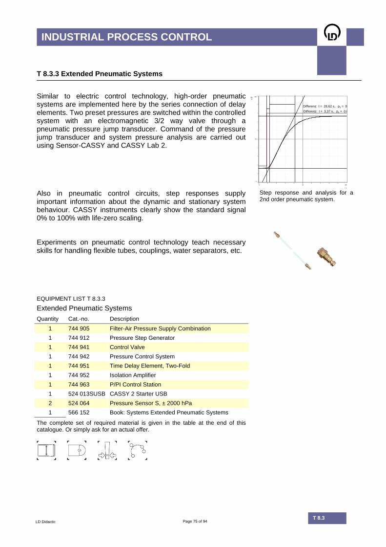
Similar to electric control technology, high-order pneumatic systems are implemented here by the series connection of delay elements. Two preset pressures are switched within the controlled system with an electromagnetic 3/2 way valve through a pneumatic pressure jump transducer. Command of the pressure jump transducer and system pressure analysis are carried out using Sensor-CASSY and CASSY Lab 2.
py
%
0
50
100
t / s
0 50 100
Differenz: t = 28,62 s, py = 0,0 %
Differenz: t = 3,37 s, py = 0,0 %
Also in pneumatic control circuits, step responses supply important information about the dynamic and stationary system behaviour. CASSY instruments clearly show the standard signal 0% to 100% with life-zero scaling.
Step response and analysis for a 2nd order pneumatic system.
Experiments on pneumatic control technology teach necessary skills for handling flexible tubes, couplings, water separators, etc.
EQUIPMENT LIST T 8.3.3
Extended Pneumatic Systems
Quantity Cat.-no. Description
1 744 905 Filter-Air Pressure Supply Combination
1 744 912 Pressure Step Generator
1 744 941 Control Valve
1 744 942 Pressure Control System
1 744 951 Time Delay Element, Two-Fold
1 744 952 Isolation Amplifier
1 744 963 P/PI Control Station
1 524 013SUSB CASSY 2 Starter USB
2 524 064 Pressure Sensor S, ± 2000 hPa
1 566 152 Book: Systems Extended Pneumatic Systems
The complete set of required material is given in the table at the end of this catalogue. Or simply ask for an actual offer.
Page 76 of 94 T 8.2
INDUSTRIAL PROCESS CONTROL
LD Didactic T 8.3
T 8.3.4 Process with Industrial Control
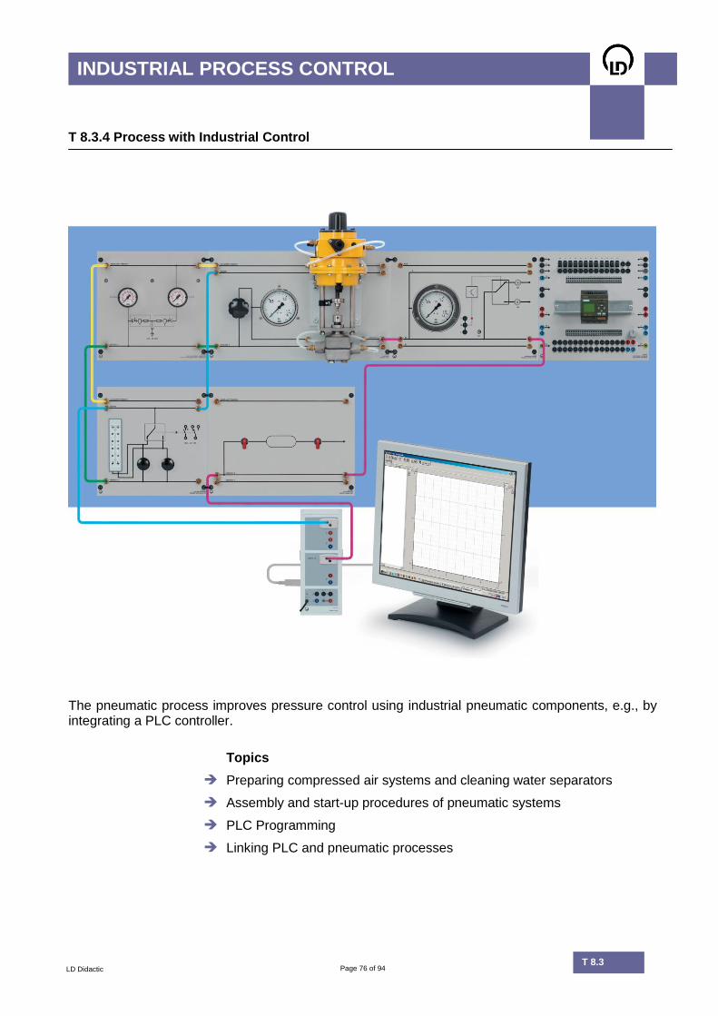
The pneumatic process improves pressure control using industrial pneumatic components, e.g., by integrating a PLC controller.
Topics
Preparing compressed air systems and cleaning water separators
Assembly and start-up procedures of pneumatic systems
PLC Programming
Linking PLC and pneumatic processes
Page 77 of 94 T 8.2
INDUSTRIAL PROCESS CONTROL
LD Didactic T 8.3
T 8.3.4 Process with Industrial Control
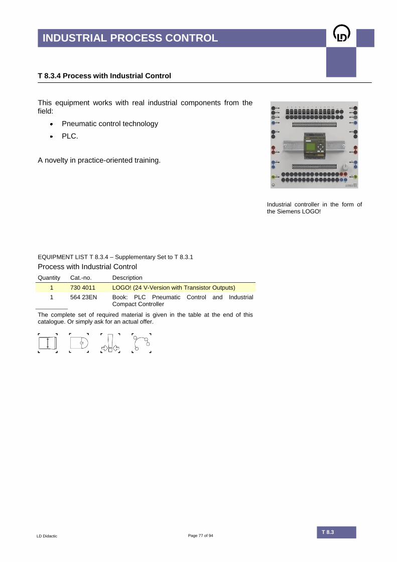
This equipment works with real industrial components from the field:
Pneumatic control technology
PLC.
A novelty in practice-oriented training.
Industrial controller in the form of the Siemens LOGO!
EQUIPMENT LIST T 8.3.4 – Supplementary Set to T 8.3.1
Process with Industrial Control
Quantity Cat.-no. Description
1 730 4011 LOGO! (24 V-Version with Transistor Outputs)
1 564 23EN Book: PLC Pneumatic Control and Industrial Compact Controller
The complete set of required material is given in the table at the end of this catalogue. Or simply ask for an actual offer.

Page 78 of 94 T 8.2
INDUSTRIAL PROCESS CONTROL
LD Didactic T 8.3
T 8.3.5 Control with Compact Controller
The SIPART Compact Controller works within an electronic controlled system.
Topics
Setup procedure for the SIPART DR19 control station
Integrating controllers in different control circuits.
Page 79 of 94 T 8.2
INDUSTRIAL PROCESS CONTROL
LD Didactic T 8.3
T 8.3.5 Control with Compact Controller
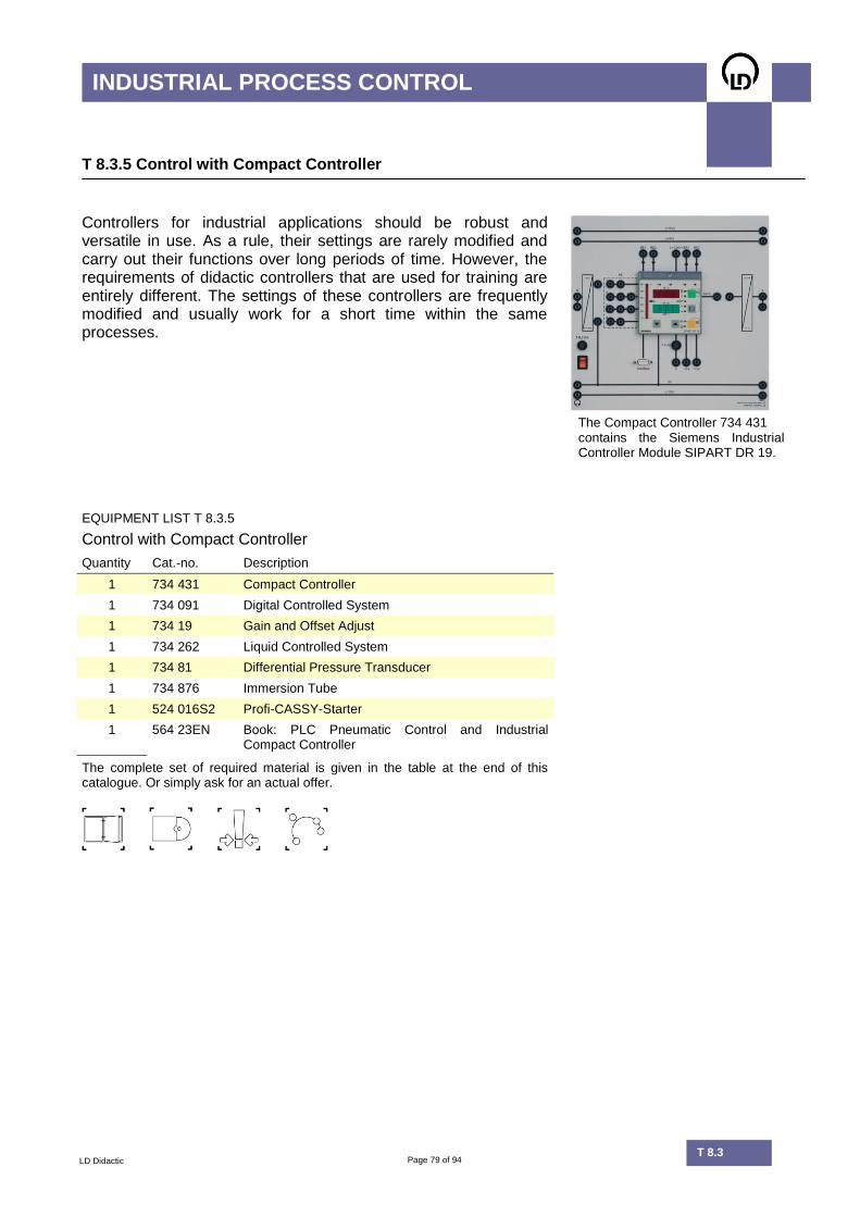
Controllers for industrial applications should be robust and versatile in use. As a rule, their settings are rarely modified and carry out their functions over long periods of time. However, the requirements of didactic controllers that are used for training are entirely different. The settings of these controllers are frequently modified and usually work for a short time within the same processes.
The Compact Controller 734 431
contains the Siemens Industrial Controller Module SIPART DR 19.
EQUIPMENT LIST T 8.3.5
Control with Compact Controller
Quantity Cat.-no. Description
1 734 431 Compact Controller
1 734 091 Digital Controlled System
1 734 19 Gain and Offset Adjust
1 734 262 Liquid Controlled System
1 734 81 Differential Pressure Transducer
1 734 876 Immersion Tube
1 524 016S2 Profi-CASSY-Starter
1 564 23EN Book: PLC Pneumatic Control and Industrial Compact Controller
The complete set of required material is given in the table at the end of this catalogue. Or simply ask for an actual offer.

Page 80 of 94 T 8.2
INDUSTRIAL PROCESS CONTROL
LD Didactic T 8.3
T 8.3.6 Control of Industrial Machine 300 W
Topics
Use of manual-automatic switches
Preliminary manual adjustment of control circuits
Speed control
Recording step responses
Dimensioning controllers

Page 81 of 94 T 8.2
INDUSTRIAL PROCESS CONTROL
LD Didactic T 8.3
T 8.3.6 Control of Industrial Machine 300 W
This equipment works with an industrial machine in motor-operation. In the experiment one is trained to handle the mains voltage.
EQUIPMENT LIST T 8.3.6
Controlling a 300 W Industrial Machine
Quantity Cat.-no Description
1 734 02 Reference Variable Generator
1 734 064 PID Digital Controller
1 734 16 Manual/Automatic Switch
1 734 19 Gain and Offset Adjust
1 734 22 Actuator 115...230V/1KW
1 731 91 Shunt Wound Machine 0.3
1 731 09 Tachogenerator 0.1/0.3
1 524 016S2 Profi-CASSY-Starter
1 568 062 Book: Applied Process Control System I
The complete set of required material is given in the table at the end of this catalogue. Or simply ask for an actual offer.
Page 82 of 94 T 8.2
INDUSTRIAL PROCESS CONTROL
LD Didactic T 8.3
T 8.3.7 Heating Control
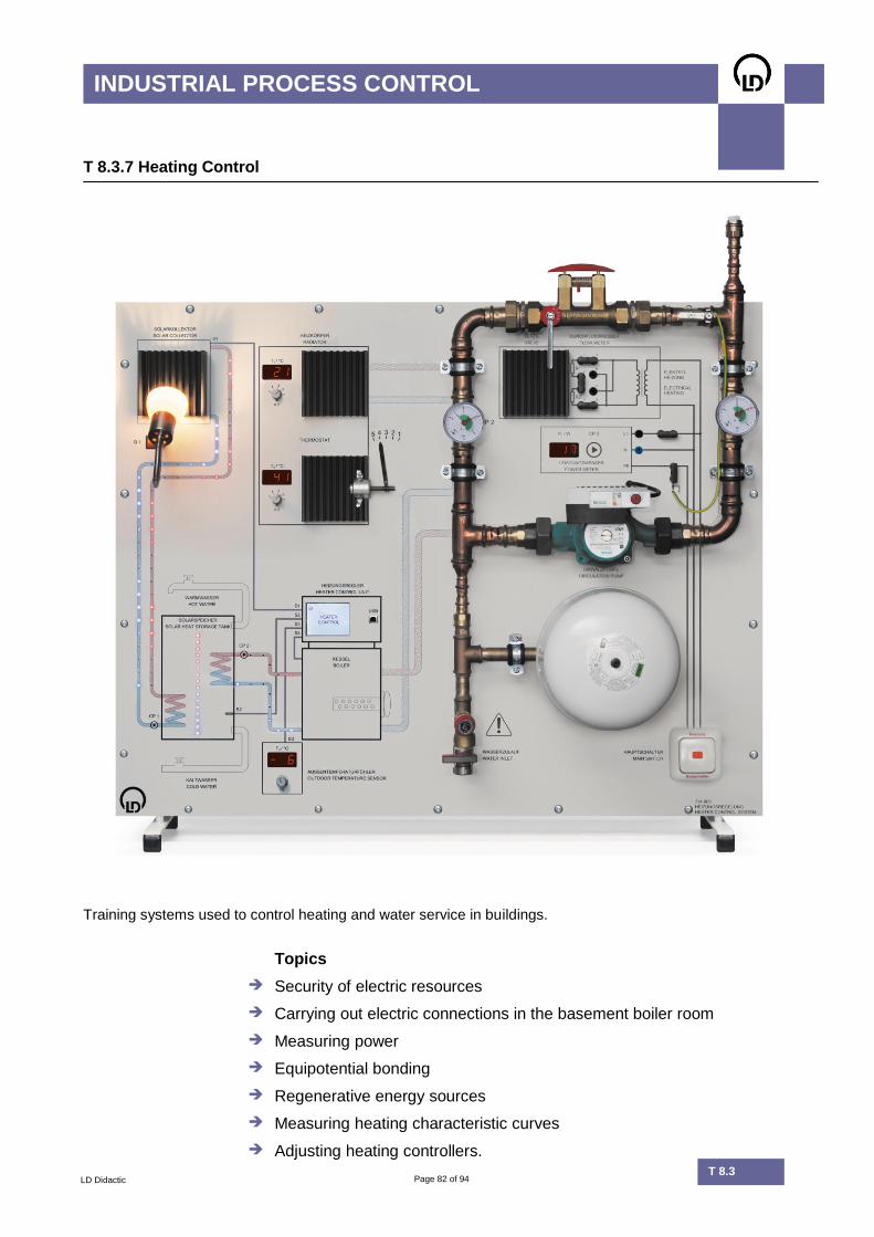
Training systems used to control heating and water service in buildings.
Topics
Security of electric resources
Carrying out electric connections in the basement boiler room
Measuring power
Equipotential bonding
Regenerative energy sources
Measuring heating characteristic curves
Adjusting heating controllers.
Page 83 of 94 T 8.2
INDUSTRIAL PROCESS CONTROL
LD Didactic T 8.3
T 8.3.7 Heating Control
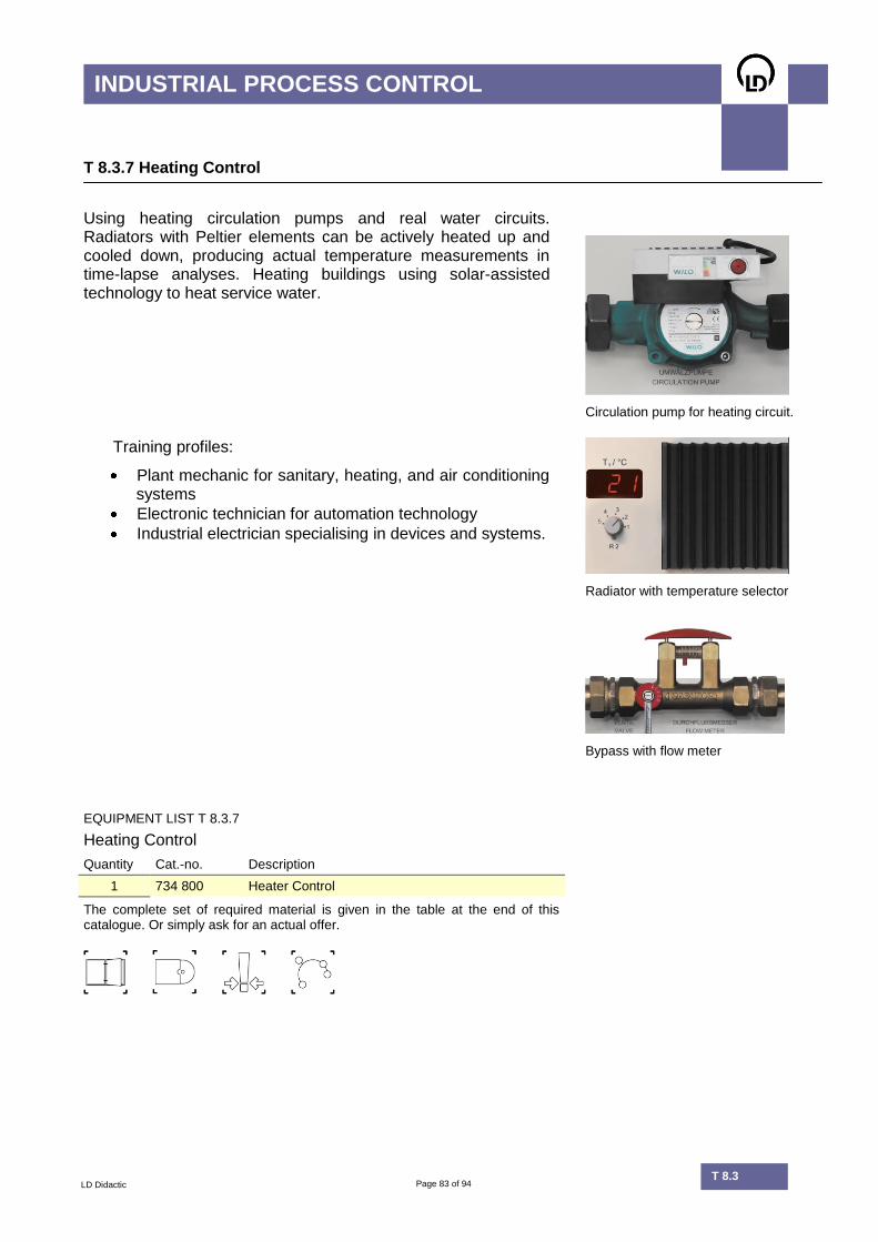
Using heating circulation pumps and real water circuits. Radiators with Peltier elements can be actively heated up and cooled down, producing actual temperature measurements in time-lapse analyses. Heating buildings using solar-assisted technology to heat service water.
Circulation pump for heating circuit.
Training profiles:
Plant mechanic for sanitary, heating, and air conditioning systems
Electronic technician for automation technology
Industrial electrician specialising in devices and systems.
Radiator with temperature selector
Bypass with flow meter
EQUIPMENT LIST T 8.3.7
Heating Control
Quantity Cat.-no. Description
1 734 800 Heater Control
The complete set of required material is given in the table at the end of this catalogue. Or simply ask for an actual offer.
Page 84 of 94 T 8.2
INDUSTRIAL PROCESS CONTROL
LD Didactic T 8.3
T 8.3.8 COM3LAB-Multimedia: Electro Pneumatics
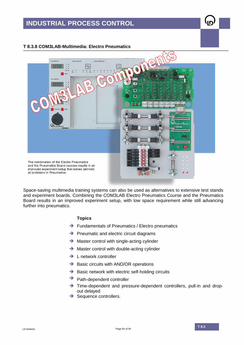
Space-saving multimedia training systems can also be used as alternatives to extensive test stands and experiment boards. Combining the COM3LAB Electro Pneumatics Course and the Pneumatics Board results in an improved experiment setup, with low space requirement while still advancing further into pneumatics.
Topics
Fundamentals of Pneumatics / Electro pneumatics
Pneumatic and electric circuit diagrams
Master control with single-acting cylinder
Master control with double-acting cylinder
L network controller
Basic circuits with AND/OR operations
Basic network with electric self-holding circuits
Path-dependent controller
Time-dependent and pressure-dependent controllers, pull-in and drop-out delayed
Sequence controllers.

Page 85 of 94 T 8.2
INDUSTRIAL PROCESS CONTROL
LD Didactic T 8.3
T 8.3.8 COM3LAB-Multimedia: Electro Pneumatics
The COM3LAB course Electro Pneumatics imparts basic knowledge of pneumatics and electro pneumatics. The operation principles of pneumatic and electric circuits are graphically presented with the help didactical standard exercises. The COM3LAB Board is combined with an Industrial Valve Technology Board, or a COM3LAB Pneumatic Board, for experimentation. The course contains the following components:
Relay, 4 change-over contacts
Timing relay (pull-in and drop-out delayed)
P/E converter
Pressure sensor 0 - 10 bar
Operation and observation elements
24 V voltage supply. The COM3LAB course Pneumatics Board (700 351) is a supplement to the COM3LAB Electro Pneumatics Course. The Pneumatics Board is directly connected to the COM3LAB Electro Pneumatics Course, which monitors the status of components through the cylinder’s integrated displacement sensor. Components:
Single-acting cylinder, spring recoverable with capacitive limit switch
Double-acting cylinder with displacement sensor and cylinder switch
Throttle check valves
5/2 way valves electrically operated, spring recoverable
5/2 way valves electrically operated, pulse valve Central closing valve for pressure supply
Displacement sensor for the double-acting cylinder.
UAV
0
5
10
t / s
0 10 20
EQUIPMENT LIST T 8.3.8
COM3LAB-Multimedia: Electro Pneumatics
Quantity Cat.-no. Description
1 700 00 USB Master Unit
1 700 35 COM3LAB Course: Electro Pneumatics
1 700 351 COM3LAB Course: Pneumatics Board
1 Compressor
The complete set of required material is given in the table at the end of this catalogue. Or simply ask for an actual offer.

Page 86 of 94 T 8.2
INDUSTRIAL PROCESS CONTROL
LD Didactic T 8.2
Equipment Sets T 8.1
Cat.-no. Description 8.1
.1.1
8.1
.2.1
8.1
.2.2
8.1
.2.3
8.1
.3
311 87 Dial Gauge 1
700 11 C3L-Course: DC Technology I 1
700 12 C3L-Course: DC Technology II 1
700 13 C3L- Course: AC Technology I 1
700 14 C3L- Course: AC Technology II 1
700 84 C3L- Course: Sensor Techno. 1
727 41 Measurement Value Indicator (1) (1)
727 549N Basic Set T 6.1.11
727 66 DC Bridge Amplifier 1 1
734 02 Reference Variable Generator 1
734 13 Power Amplifier 1
743 301 Standard Kit Sensors 1
734 302 Extension Kit Sensors 1
734 303 Case Test Samples 1
734 304 Teachware Sensoric 1
734 38 Oven Model 20 V, 20 W 1
734 55 Strain Gauge Transducer 1
734 56 Tensile Test Bar 1
734 565 Torsion Bar 1
734 74 NiCr-Ni Thermoelement 1
734 75 Thermocouple Connection 1
734 76 Pt-100 Resistance Probe. 1
734 77 NTC Temperature Probe 1
(): Recommended

Page 87 of 94 T 8.2
INDUSTRIAL PROCESS CONTROL
LD Didactic T 8.2
Equipment Sets T 8.1
Cat.-no. Description 8.1
.1.1
8.1
.2.1
8.1
.2.2
8.1
.2.3
8.1
.3
Accessories
315 36 Set of 7 Weights, 0.1 to 2 kg 1
500 98 6 Safety Adapter Sockets, black 1
501 48 Set of 10 Bridging Plugs 2
501 511 Set of 10 Bridging Plugs 2 3
501 512 Set of 10 Bridging Plugs with Tap
1 1
501 532 Set of 30 Connecting Leads 1 1 1
524 013SUSB CASSY 2 Starter USB 1 1 1
562 793NA Power Supply 6 - 24 V 1
577 32 Resistor 100 , 2 W 3
577 38 Resistor 330 , 2 W 3
577 60 Resistor 22 , 0.5 W 1
577 64 Resistor 47 , 0.5 W 1
577 657 Resistor 68 , 0.5 W 1
577 68 Resistor 100 , 0.5 W 1
577 71 Resistor 220 , 0.5 W 1
577 97 Resistance Decade 1
664 121 Beaker 1
700 00USB Master Unit 1
700 00CBTDE COM3LAB Software German 1
726 09 Panel Frame T 130 1 1
726 50 Plug-In Board 997 x 300 1
726 86 Stab. Power Supply 15 V / 3 A 1 1
726 88 AC/DC Stabilizer 1
726 961 Function Generator 200 kHz 1
Literature
565 851 Electronic Meas.Device Circuits 1
568 271 Force Meas. with Strain Gauge 1
568 301 Temperature Measurement 1

Page 88 of 94 T 8.2
INDUSTRIAL PROCESS CONTROL
LD Didactic T 8.2
Equipment Sets T 8.2
Cat.-no. Description 8.2
.1.1
8.2
.1.2
8.2
.1.3
8.2
.1.4
8.2
.1.5
8.2
.1.6
8.2
.1.7
8.2
.2
8.2
.3
8.2
.4
8.2
.5
8.2
.6
8.2
.7
8.2
.8
666 630 Blower 1
666 633 Thermal Anemometer 1
666 632 Windmill Type Anemometer 1
700 81 C3L: Operational amplifier 1
700 82 C3L: Control Technology I 1
700 83 C3L: Control Technology II 1
700 84 C3L: Sensor Technology 1
734 011 Two-Position Controller 1 1
734 02 Reference Variable Generator 1 1 1 1 1 1 1 1 1
734 03 P Controller 1
734 04 I Element 1 1
734 05 D Element 1
734 064 PID Digital Controller 1 1 1 1 1 1 1 1 1 1
734 07 Summing Point, 2 Inputs 1
734 08 Summing Point, 5 Inputs 1 1 1
734 0891 Dead Time Element 1 1 1
734 091 Digital Controlled System 2 1 2 2
734 0951 2nd Order Transfer Element 1 1 1
734 111 Set of Machines 10 W 1 1
734 12 Temperature Controlled System 1 1
734 13 Power Amplifier 2 2
734 262 Liquid Controlled System 1 1
734 264 Additional Reservoir (1)
734 300 Listing Controlled System 1 1
734 311 Light Controlled System 1
734 41 Sample and Hold Element 1
734 481 WinFACT C3L / CASSY Edition (1) (1) (1) (1) (1) (1) (1) (1) 1 1 (1)
734 491 WinFACT LD Licence 1 1
734 81 Diff. Pressure Transducer 1
734 861 Capacitive Bar-Type Probe (1)
734 876 Immersion Tube 1
734 881 Level Switch with Float (1)
734 89 Capacitive Level Switch (1)
(): recommended

Page 89 of 94 T 8.2
INDUSTRIAL PROCESS CONTROL
LD Didactic T 8.2
Equipment Sets T 8.2
Cat.-no. Description 8.2
.1.1
8.2
.1.2
8.2
.1.3
8.2
.1.4
8.2
.1.5
8.2
.1.6
8.2
.1.7
8.2
.2
8.2
.3
8.2
.4
8.2
.5
8.2
.6
8.2
.7
8.2
.8
Accessories
510 48 Pair of Magnets 1 1
501 511 10 Bridging Plugs, black 2 2 2 2 1 1 2 3 3 3 3 3 3
501 512 10 Bridging Plugs with Tap 1 1 1 1 1 1 1 1 1 1 1 1 1
501 532 30 Connection Leads, 1 mm² 1 1 1 1 1 1 1 1 1 1 1 1 1
524 016S2 Profi-CASSY-Starter 2 USB 1 1 1 1 1 1 1 1 1 1 1 1 1
700 00CBTEN C3L-Software English 1
700 00USB C3L Master Unit (USB) 1
726 09 Panel Frame, T130, Two Levels 1 1 1 1 1 1 1 1 1 1 1 1 1
726 86 Stab. Power Supply +/-15V/3 A 1 1 1 1 1 1 1 1 1 1 1 1 1
Literature
564 19EN Control of Electronic Systems 1 1
564 20EN Measurement of Frequency Responses
1
564 21EN Stability & Optimisation 1
564 22EN Digital Controllers 1
564 24EN Control of Technical Systems 1 1 1 1 1 1 1
568 222 Fundamentals of Automatic Control Technology II, Vol. 2
1 1 1 1 1 1 1 1 1
568 232 Fundamentals of Automatic Control Technology II, Vol. 1
1 1
568 342 Flow Measuring of Gases 1
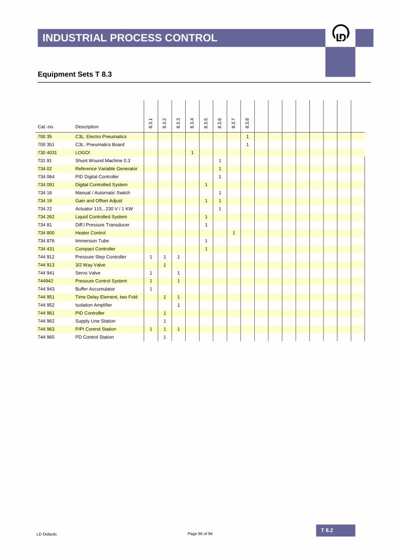
Page 90 of 94 T 8.2
INDUSTRIAL PROCESS CONTROL
LD Didactic T 8.2
Equipment Sets T 8.3
Cat.-no. Description 8.3
.1
8.3
.2
8.3
.3
8.3
.4
8.3
.5
8.3
.6
8.3
.7
8.3
.8
700 35 C3L: Electro Pneumatics 1
700 351 C3L: Pneumatics Board 1
730 4031 LOGO! 1
731 91 Shunt Wound Machine 0.3 1
734 02 Reference Variable Generator 1
734 064 PID Digital Controller 1
734 091 Digital Controlled System 1
734 16 Manual / Automatic Switch 1
734 19 Gain and Offset Adjust 1 1
734 22 Actuator 115...230 V / 1 KW 1
734 262 Liquid Controlled System 1
734 81 Diff.l Pressure Transducer 1
734 800 Heater Control 1
734 876 Immersion Tube 1
734 431 Compact Controller 1
744 912 Pressure Step Controller 1 1 1
744 913 3/2 Way Valve 1
744 941 Servo Valve 1 1
744942 Pressure Control System 1 1
744 943 Buffer Accumulator 1
744 951 Time Delay Element, two Fold 1 1
744 952 Isolation Amplifier 1
744 961 PID Controller 1
744 962 Supply Line Station 1
744 963 P/PI Control Station 1 1 1
744 965 PD Control Station 1
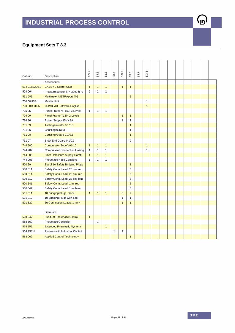
Page 91 of 94 T 8.2
INDUSTRIAL PROCESS CONTROL
LD Didactic T 8.2
Equipment Sets T 8.3
Cat.-no. Description 8.3
.1
83.2
83.3
83.4
8.3
.5
83.6
83.7
8.3
.8
Accessories
524 016S2USB CASSY 2 Starter USB 1 1 1 1 1
524 064 Pressure sensor S, 2000 hPa 2 2 2
531 583 Multimeter METRAport 40S 3
700 00USB Master Unit 1
700 00CBTEN COM3LAB Software English 1
725 25 Panel Frame VT150, 3 Levels 1 1 1
726 09 Panel Frame T130, 2 Levels 1 1
726 86 Power Supply 15V / 3A 1 1
731 09 Tachogenerator 0.1/0.3 1
731 06 Coupling 0.1/0.3 1
731 08 Coupling Guard 0.1/0.3 1
731 07 Shaft End Guard 0.1/0.3 2
744 900 Compressor Type V01-10 1 1 1 1
744 902 Compressor Connection Hosing 1 1 1 1
744 905 Filter / Pressure Supply Comb. 1 1 1
744 906 Pneumatic Hose Couplers 1 1 1
500 59 Set of 10 Safety Bridging Plugs 1
500 611 Safety Conn. Lead, 25 cm, red 6
500 611 Safety Conn. Lead, 25 cm, red 6
500 612 Safety Conn. Lead, 25 cm, blue 6
500 641 Safety Conn. Lead, 1 m, red 6
500 6421 Safety Conn. Lead, 1 m, blue 6
501 511 10 Bridging Plugs, black 1 1 1 3 2
501 512 10 Bridging Plugs with Tap 1 1
501 532 30 Connection Leads, 1 mm² 1 1
Literature
568 042 Fund. of Pneumatic Control 1
568 162 Pneumatic Controller 1
568 152 Extended Pneumatic Systems 1
564 23EN Process with Industrial Control 1 1
568 062 Applied Control Technology 1

Page 92 of 94 T 8.2
INDUSTRIAL PROCESS CONTROL
LD Didactic T 8.2
Keywords
2
2nd order system, 8
3
3D characteristic field, 52
A
Amplitude response, 60 Anemometer, 40 Attenuation, 60 Automation, 3 Auxiliary power supply, 68
B
Block diagrams, 54 Bode diagram, 59 Buffer storage tank, 72
C
Circle diagram, 59 Closed loop mode, 36 Compact controllers, industrial, 67 Compressor, 70 Control algorithms, 50 Control system parameter, manual adjustment, 55 Control systems with dead time, 53 Control systems with start time, 53 Control technology, industrial, 67 Control technology, multimedia course, 64 Control, continuous, 53 Control, discontinuous, 53 Control, quasi-continuous, 53 Controlled systems, 58 Controller parameters, 54 Controller, digital, 57 Curve families, 73 Cylinder, double-acting, 85
D
Delay network, 75 Differential pressure sensor, 37 Direction of action, 71 Displaying processes, 33 Disturbance reaction, 34, 42, 71
E
Electro pneumatics, 85, 86 Energy sources, regenerative, 83 Equipotential bonding, 83 Evolution strategy, 62

Page 93 of 94 T 8.2
INDUSTRIAL PROCESS CONTROL
LD Didactic T 8.2
F
Feedback, 53 Flow, 35 Fluid controlled systems, 35 Follow-up control, 48 Frequency response, 59 Fuzzy control, 49, 50 Fuzzy set, 52
H
Heating characteristic curve, 83 Heating circulation pump, 84 Heating controller, 83 Heating of buildings, 84 Heating of service water, 84
I
Immersion pipe, 37 Incremental transducer, 7 Industrial valve technology, 86 Integral criteria, 61 ITAE, 62
L
Level, 35 Light controlled systems, 41 Linguistic output variable, 52 Linguistic rules, 49 Live Zero, 68
M
Master control, 85 Master control station, 70 Measuring instrument, scale, 55 Multimedia, 26
O
On-off controllers with delayed feedback, 23 Open loop mode, 36 Open-loop control, 53 Optimisation, numerical, 62
P
Parameter, 7 Peltier elements, 84 PLC controller, 77 Plotter, 47 Pneumatics, 85 Position control, 45 Pressure jumps, 68 Pressure sensor, 86 Process control, 68

Page 94 of 94 T 8.2
INDUSTRIAL PROCESS CONTROL
LD Didactic T 8.2
Process visualisation, 47 PROFIBUS interfaces, 10 Profi-CASSY, 10, 47 Programming, block oriented, 58 Programming, with mathematical relationships, 58 PT1 element, 60 PT2 element, 60
Q
Quality criteria, 62
R
Response speed, 32 Response to setpoint changes, 42, 71
S
Sample & Hold, 57 Sampling element, 57 SCADA, 33 Sequence controllers, 85 Servo valve, 72 Signal line, 72 Simulation, 54 Simulation of technical control circuits, 59 SIPART DR 19, 70 Slope, 60 Software controllers, 58 Step response, 35, 53 Summation points, 56 System optimisation, 61 System order, determination, 59
T
Temperature sensor, 34 Thermal cross, 40 Thermosensor, 40 Throttle check valves, 86 Time constants, 32, 54 Transfer elements, classic, 54
V
Valve, pneumatic, 68
W
Water separator, 77 WinFACT, 47


PHYSICS
1345
002-
T8
Mea
sure
men
t an
d Co
ntro
l Tec
hnol
ogy–
22.
12
LD DIDACTIC GMbHLeyboldstraße 1D- 50354 HürthTel.: +49(0)2233- 604-0Fax: +49(0)2233- 604-222E-Mail: [email protected]
www.LD-DIDACTIC.COM