mechanical technical report 2
TRANSCRIPT

Kevin Kaufman Straumann USA Mechanical Option Andover, MA Faculty Consultant: Dr. Bahnfleth _____________________________________________________________________
Mechanical Technical Report 2 Building and Plant Energy Analysis Report
Straumann USA Andover, MA
October 27, 2006
Kevin Kaufman Straumann USA Mechanical Option Andover, MA Faculty Consultant: Dr. Bahnfleth _____________________________________________________________________
- 1 -
Table of Contents
1.0 Executive Summary................................................................................................ 2 2.0 Introduction ............................................................................................................. 3 3.0 LEED-NC Version 2.2............................................................................................. 4 4.0 Building Envelope – ASHRAE Standard 90.1-2004 .................................................. 5 5.0 HVAC Systems – ASHRAE Standard 90.1-2004.................................................... 6 6.0 Service Water Heating – ASHRAE Standard 90.1-2004......................................... 9 7.0 Power – ASHRAE Standard 90.1-2004 .................................................................. 9 8.0 Lighting – ASHRAE Standard 90.1-2004................................................................ 9 9.0 Loads Estimates ................................................................................................... 10 10.0 Energy Consumption and Operation Costs .......................................................... 12 11.0 References ........................................................................................................... 15 12.0 Appendix A – LEED-NC Version 2.2 Evaluation ................................................... 16 13.0 Appendix B – Space by Space Lighting Power Density Calculations ................... 18 14.0 Appendix C – HAP System Sizing......................................................................... 23 15.0 Appendix D – Schedules ...................................................................................... 36 16.0 Appendix E – Equipment Characteristics.............................................................. 39 17.0 Appendix F – Energy and Cost Analysis............................................................... 42

Kevin Kaufman Straumann USA Mechanical Option Andover, MA Faculty Consultant: Dr. Bahnfleth _____________________________________________________________________
- 2 -
1.0 Executive Summary This report analyzes the Straumann USA facility to determine the number of expected LEED points generated and compliance with ASHRAE Standard 90.1-2004. A load and energy analysis is also performed, and compared with the design loads, and yearly energy data. Straumann USA was not designed to be a LEED certified building but it did meet the requirements of 4 LEED points. However, the facility only met 3 of the 7 prerequisites. Several categories such as Sustainable Sites, Materials & Resources, and Water Efficiencies might have been able to produce points, but since LEED certification was not a goal of the project, such requirements were not pursued. Overall, Straumann USA does not comply with the requirement of ASHRAE Standard 90.1-2004. However, there were several sections where the building did fully comply including the service water heating, power, and lighting sections of ASHRAE Standard 90.1. The building envelope section did not comply based on the vertical fenestration U, and SHGC values. Fan power limitations, and insulation thicknesses prevented section 6, HVAC systems, from complying. The load estimate and energy cost summaries are summarized in Table 1.1. The cooling load and ventilation rates are reasonably comparable to the design values. However, the estimated heating load is significantly different, and could be attributed to the estimated distribution of lighting loads to the space and plenum. Since the heating loads are quite different, this also results in a large difference in fuel costs which serves only heating loads. The electricity costs estimated are actually close to those actually seen by Straumann USA. The slight variation could be a result of higher lighting and power requirements per square foot, or the application of the utility rates to the estimated load.
Estimated DesignSupply Air (CFM) 260992 282183Cooling Load (MBH) 9388 8088Heating Load (MBH) 1076 2786
Estimated AcutalFuel Costs $19,277 $75,000Electric Costs $673,710 $622,650
Annual Comparisons
Table 1.1 Annual Load, Ventilation, and Cost Comparisons

Kevin Kaufman Straumann USA Mechanical Option Andover, MA Faculty Consultant: Dr. Bahnfleth _____________________________________________________________________
- 3 -
2.0 Introduction Straumann USA is a combination manufacturing/office building located in Andover, MA. The Straumann facility is actually a portion of the larger 100 Minuteman Building, but is separated from the rest of a building by a firewall for zoning reasons. The Straumann USA projected included the gutting and complete renovation of the Straumann portion of the building. The central plants were not located on this side of the building and were not altered during this project. Since the Straumann facility is only a two story building, and some areas are not a full two stories, there was no need for any duct or piping shafts. There was no lost rentable space in the Straumann USA space. All piping was run in plenums, or standard framed walls. The ductwork was also able to be run in a fashion where the plenum spaces were utilized avoiding any risers through the building floors. All of the central plant equipment was located on the other half of the building and all air-handlers were located on the roof of the Straumann facility. There were a few bulkheads that were created for some of the larger ducts but this had no effect on the rentable floor area. The mechanical system first cost for the project was $2.5 million, or $9.88/ft2.
Kevin Kaufman Straumann USA Mechanical Option Andover, MA Faculty Consultant: Dr. Bahnfleth _____________________________________________________________________
- 4 -
3.0 LEED-NC Version 2.2 The Leadership in Environmental Engineering Design Green Building Rating System is the nationally accepted benchmark for the design construction, construction, and operation of green buildings. The LEED system was created by the U.S. Green Building Council in order to make a credible standard for what constitutes a green building. There are several advantages associated with a LEED certified building. They typically provide healthy and comfortable spaces for occupants, reduce waste sent to landfills, conserve energy and water, and specifically in Massachusetts a green building tax program is being considered. The Straumann USA Facility renovation project was not designed to attain any LEED ratings. The project was analyzed however to determine which the areas where LEED points would have been obtained. According to the analysis performed in this report, it was determined that a total of 4 points would have been obtained above the prerequisites. Of the perquisites, only three of the seven were met. A summary of LEED points earned are listed in Appendix A.

Kevin Kaufman Straumann USA Mechanical Option Andover, MA Faculty Consultant: Dr. Bahnfleth _____________________________________________________________________
- 5 -
4.0 Building Envelope ASHRAE Standard 90.1-2004 ASHRAE Standard 90.1-2004 provides minimum requirements for energy-efficient buildings with the exception of low rise residential buildings. Section 5 of ASHRAE Standard focuses on the specific requirements for the building envelope. Located in Andover, MA, Straumann USA is in climate zone 5 as specified in Table B-1 of ASHRAE Standard 90.1. This is used to determine the building envelope requirements for the facility. The results of the analysis are listed in Table 4.1. The first calculation of fenestration percentage for the building included the only the Straumann USA building. This resulted in 61.4% which is a larger area than allowed by Standard 90.1. However, upon further inspection of the entire 100 Minuteman building, the fenestration percentage was found to be 49% which is below the allowable limits. The entire building fenestration (49%) and was used for evaluating the fenestration heat transfer coefficient and solar heat gain coefficients, since Tables 5.5 in Standard 90.1 do not have compliance values for any fenestration above 50%.
Description Actual Used in Straumann USA
Standard 90.1 Compliance Value Compliance
Roof (Inuslated Entirely Above Deck) U = 0.061 Max U = 0.063 YesWalls (Steel Framed) U = 0.055 Max U = 0.084 YesSlab on Grade Floor (unheated) F = 0.21 Max F = 0.730 YesFenstration (40.1-50%, Fixed) U = 0.5 Max U = 0.46 No
SHGC = 0.42 Max SHGCall = 0.26 NoMax SHGCnorth = 0.36 No
Skylight (0-2%, Fixed) U = 0.5 Max = 1.17 YesSHGC = 0.42 Max SHGCall = 0.49 Yes
Section 5 Compliance No
ASHRAE Standard 90.1-2004Section 5 Building Envelope
Climate Zone 5
Table 4.1 – ASHRAE Standard 90.1-2004 Building Envelope Compliance
The results of the analysis show that the Straumann USA facility does not comply with the building envelope criteria for the vertical fenestration.

Kevin Kaufman Straumann USA Mechanical Option Andover, MA Faculty Consultant: Dr. Bahnfleth _____________________________________________________________________
- 6 -
5.0 HVAC Systems – ASHRAE Standard 90.1-2004 Section 6 of ASHRAE Standard 90.1-2004 specifies minimum efficiencies for mechanical equipment, insulation requirements for piping, and insulation requirements for ductwork. According to section 6.1.1 of Standard 90.1 only new equipment must comply. If existing systems are being used as in the case of the Straumann USA facility, the existing equipment does not need to comply with the minimum efficiencies specified. A summary of mechanical equipment compliances to Standard 90.1 section 6 can be found in Tables 5.1 – Table 5.3. Insulation compliances for piping and ductwork can be found in Table 5.5 and Table 5.4 respectively.
Section Description Unit MBH Compliance6.5.1 RTU-1 984.9 Yes
RTU-2 984.9 YesRTU-3 310 YesRTU-4 984.9 YesRTU-5 667 YesRTU-6 667 YesRTU-7 984.9 YesRTU-8 984.9 YesRTU-9 984.9 Yes
RTU-10 984.9 Yes
Air Economing for sytesms greater than 65 MBH
Table 5.1 ASHRAE 90.1-2004 Economizer Compliance
Section Description Unit hp/cfm Compliance6.5.3.1 Fan Power Limitation RTU-1 1.5 No
> 20,000 cfm (VAV) RTU-2 1.5 Nomax of 1.5hp/cfm RTU-3 1.2 No<20,000 cfm (CAV) RTU-4 1.5 Nomax of 1.5hp/cfm RTU-5 1.5 No
RTU-6 1.5 NoRTU-7 1.5 NoRTU-8 1.5 NoRTU-9 1.5 No
RTU-10 1.5 No
Table 5.2 ASHRAE 90.1-2004 Fan Power Compliance

Kevin Kaufman Straumann USA Mechanical Option Andover, MA Faculty Consultant: Dr. Bahnfleth _____________________________________________________________________
- 7 -
Section Description Unit SEER Compliance6.8.1 Air Cooled Air Conditioners AC-3 11.6 Yes
(split sytem) AC-6 11.6 Yes< 65 MBH Min of 10.0 SEER AC-7 11.6 Yes
AC-8 11.6 YesAC-9 11.6 Yes
>65MBH, <135 MBH AC-1 16.5 Yes10.3 SEER AC-2 16.5 Yes
AC-4 16.5 YesAC-5 16.5 Yes
Table 5.2 ASHRAE 90.1-2004 Mechanical Equipment Compliance
Space TypeMinimum Insulation Required
Insulation Used Compliance
Indirectly Conditioned Space (plenum) none 1.5" mineral
fiber blanket Yes
Exterior R-6 1.5" mineral fiber blanket Yes
Duct Insulation - Climate Zone 5Section 6 HVAC
ASHRAE Standard 90.1-2004
Table 5.4 Minimum Duct Insulation

Kevin Kaufman Straumann USA Mechanical Option Andover, MA Faculty Consultant: Dr. Bahnfleth _____________________________________________________________________
- 8 -
Pipe Type Supply/Return Pipe SizeMinumum Insulation Required
Inuslation Used Compliance
Hot Water Supply < 1" 1.5 1 No1" - < 1.5" 1.5 1 No1.5" - < 2" 2 1 No1.5 " - < 4" 2 1.5 No
4" - < 8" 2 1.5 No> 8" 2 1.5 No
Return < 1" 1 1 Yes1" - < 1.5" 1 1 Yes1.5" - < 2" 1 1 Yes1.5 " - < 4" 1 1.5 Yes
4" - < 8" 1.5 1.5 Yes> 8" 1.5 1.5 Yes
Chilled Water < 1" 0.5 1.5 Yes1" - < 1.5" 0.5 1.5 Yes1.5" - < 4" 1 1.5 Yes4" - < 8" 1 1.5 Yes
> 8" 1 1.5 YesSteam Supply < 1" 1.5 1 No
1" - < 1.5" 1.5 1 No1.5" - < 2" 2 1 No1.5 " - < 4" 2 1.5 No
4" - < 8" 2 1.5 No> 8" 2 1.5 No
Condensate Return < 1" 1 1 Yes1" - < 1.5" 1 1 Yes1.5" - < 2" 1 1 Yes1.5 " - < 4" 1 1.5 Yes
4" - < 8" 1.5 1.5 Yes> 8" 1.5 1.5 Yes
ASHRAE Standard 90.1-2004Section 6 HVAC
Minimum Pipe Inuslation Thickness
Supply and Return
Table 5.5Minimum Pipe Insulation Thickness

Kevin Kaufman Straumann USA Mechanical Option Andover, MA Faculty Consultant: Dr. Bahnfleth _____________________________________________________________________
- 9 -
6.0 Service Water Heating – ASHRAE Standard 90.1-2004 No additional water heating equipment is installed in this project. Therefore, nothing needs to be evaluated by the requirements in section 7. The Straumann Project fully complies with section 7 of ASHRAE Standard 90.1-2004. 7.0 Power ASHRAE Standard 90.1-2004 According to the electrical engineer for the Straumann USA project all feeders and branch circuits were designed to comply with the voltage drop requirements of section eight of Standard 90.1. Feeders and branch circuits have a voltage drop of no more than 3% and 2% respectively. Based on this information, the project complies with section 8 of ASHRAE Standard 90.1-2004 8.0 Lighting ASHRAE Standard 90.1-2004 Section 9 of ASHRAE Standard 90.1 sets requirements on maximum lighting densities for a building. One of two ways can be used to show compliance with the standard. The space by space method can be used to show that each individual area does not exceed the lighting power density determined by the occupancy. The second method is the building area method, where the entire building is considered and the maximum power density is set by the type of building. A space by space method power density analysis was performed on the Straumann USA. However, many spaces did not comply with the maximum requirements of Standard 90.1. The results of this method can be found in Appendix B. A building are method lighting power density was also performed on the building. Since the building has to main occupancies, a weighted average of building are and occupancy type was used to calculate the allowable power density for the building. The results of this method are summarized in Table 8.1. Using the building area method, the project complies with section 9 of ASHRAE Standard 90.1-2004
Building TypeMax Power
DensityArea of
Straumann USAManufacturing 1.3 75,000Office 1 68,800Weighted Avgerage 1.16Power Density of Straumann 1.02Compliance Yes
ASHRAE Standard 90.1-2004Section 9 Lighting Power Density
Table 8.1 Lighting Power Density Building Area Method

Kevin Kaufman Straumann USA Mechanical Option Andover, MA Faculty Consultant: Dr. Bahnfleth _____________________________________________________________________
- 10 -
9.0 Load Estimation Several values were assumed in order to produce the load analysis for the Straumann USA facility. Table 9.1 summarizes the values used for this estimated load, and the original design load for the facility.
Estimated DesignOA Ventilation Rates ASHRAE Standard 62.1-2004 ASHRAE Standard 62.1-2004Lighting LoadsOffice 1.3 W/ft2 1.3 W/ft2Manufacturing 2.2 W/ft2 2.2 W/ft2Equipment LoadsOffice 3.0 W/ft2 3.0 W/ft2Manufacturing 38W/ft2 38W/ft2Design Conditions ASHRAE Fundamentals 2005 (0.4%)SummerDry Bulb 90.8 95Mean Coincident Wet B 73.1 75WinterDry Bulb 7.7 10
Load Analysis Assumptions
Table 9.1 Estimated and Design Load Assumptions The equipment actually selected and scheduled on the design drawings were oversized in order to prevent a complete renovation of the space if the needs of the tenant changes. The estimated cooling and heating loads are compared to initial load design performed by the mechanical engineering designer. The areas, locations, and occupancies of the spaces may have changed slightly from the initial design, but loads should be a reasonably good source for comparison purposes. The heating and cooling load summaries are located in Table 9.1, along with the airflow rates of each unit. Overall, the estimated cooling load is slightly higher than the design load. This could be attributed to several factors. First, Trane Trace was used to create the design loads while HAP was used for the estimates. The design loads were based on the preliminary design, and not the final construction documents. The size of some of the rooms, and occupancies may have changed slightly to create such differences. The total airflow supplied by the estimated units is slightly lower than the design airflow. This could be due to assumptions of load distributions. Since the cooling load is actually larger for the estimate but less air is supplied, it could be possible that a larger amount the roof load was assumed to directly heat the plenum air and not have as great an effect on the occupied space. The puzzling result is the heating load. The heating load of the building, should be relatively low as many of the spaces do not have any exterior wall loads. However, the
Kevin Kaufman Straumann USA Mechanical Option Andover, MA Faculty Consultant: Dr. Bahnfleth _____________________________________________________________________
- 11 -
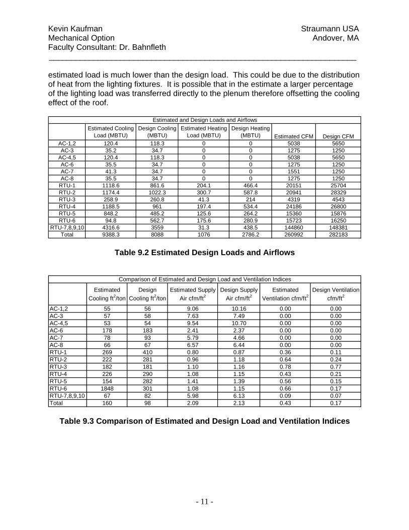
estimated load is much lower than the design load. This could be due to the distribution of heat from the lighting fixtures. It is possible that in the estimate a larger percentage of the lighting load was transferred directly to the plenum therefore offsetting the cooling effect of the roof.
Estimated Cooling Load (MBTU)
Design Cooling (MBTU)
Estimated Heating Load (MBTU)
Design Heating (MBTU) Estimated CFM Design CFM
AC-1,2 120.4 118.3 0 0 5038 5650AC-3 35.2 34.7 0 0 1275 1250
AC-4,5 120.4 118.3 0 0 5038 5650AC-6 35.5 34.7 0 0 1275 1250AC-7 41.3 34.7 0 0 1551 1250AC-8 35.5 34.7 0 0 1275 1250
RTU-1 1118.6 861.6 204.1 466.4 20151 25704RTU-2 1174.4 1022.3 300.7 587.8 20941 28329RTU-3 258.9 260.8 41.3 214 4319 4543RTU-4 1188.5 961 197.4 534.4 24186 26800RTU-5 848.2 485.2 125.6 264.2 15360 15876RTU-6 94.8 562.7 175.6 280.9 15723 16250
RTU-7,8,9,10 4316.6 3559 31.3 438.5 144860 148381Total 9388.3 8088 1076 2786.2 260992 282183
Estimated and Design Loads and Airflows
Table 9.2 Estimated Design Loads and Airflows
Estimated Cooling ft2/ton
Design Cooling ft2/ton
Estimated Supply Air cfm/ft2
Design Supply Air cfm/ft2
Estimated Ventilation cfm/ft2
Design Ventilation cfm/ft2
AC-1,2 55 56 9.06 10.16 0.00 0.00AC-3 57 58 7.63 7.49 0.00 0.00AC-4,5 53 54 9.54 10.70 0.00 0.00AC-6 178 183 2.41 2.37 0.00 0.00AC-7 78 93 5.79 4.66 0.00 0.00AC-8 66 67 6.57 6.44 0.00 0.00RTU-1 269 410 0.80 0.87 0.36 0.11RTU-2 222 281 0.96 1.18 0.64 0.24RTU-3 182 181 1.10 1.16 0.78 0.77RTU-4 226 290 1.08 1.15 0.43 0.21RTU-5 154 282 1.41 1.39 0.56 0.15RTU-6 1848 301 1.08 1.15 0.66 0.17RTU-7,8,9,10 67 82 5.98 6.13 0.09 0.07Total 160 98 2.09 2.13 0.43 0.17
Comparison of Estimated and Design Load and Ventilation Indices
Table 9.3 Comparison of Estimated and Design Load and Ventilation Indices

Kevin Kaufman Straumann USA Mechanical Option Andover, MA Faculty Consultant: Dr. Bahnfleth _____________________________________________________________________
- 12 -
10.0 Energy Consumption and Operating Cost There was no energy analysis performed for Straumann USA. There would have been an additional cost for the mechanical engineering company to perform such analysis, and the owner decided not to pursue this option. The energy analysis for performed for this report was compiled using Carrier’s Hourly Analysis Program. It was necessary to make several assumptions in regards to schedules, electric and fuel rates which can be found in Appendix D. Equipment performance characteristics are located in Appendix E. The estimated annual energy costs for Straumann USA was found to be $692,997. The HVAC energy costs account for approximately 29% ($200,561) of the total annual energy cost. Table 10.1 summarizes the costs for each system component. The results of the finding can also be seen in the form of dollars per square foot in Table 10.2. Refer to Appendix F for additional cost breakdowns, and graphs. Along with the annual costs, the annual energy consumption rates were calculated and the results are summarized in Table 10.3. Based on the results displayed in Table 10.4, the energy model predicts a slightly higher yearly electric cost, however, this could be due to the way the electric rate was calculated (Refer to Appendix D). It does not seem to be a large enough difference to cause any concern. The slight difference could also be caused by the assumed values for lighting and power per square foot differing from the amount of electricity actually consumed. Once again, the predicted steam cost is much lower than the actual cost. One possible difference could be assuming that half of the heating energy is used by the Straumann facility. Straumann USA occupies the southern portion of the building and may use less than half of the heating for the building since it would have a higher solar heat gain which would decrease the actual costs heating costs. The other factor that would play an important role is the actual design heating load. As discussed earlier, the estimated heating load was significantly lower than the design load, which would also lead to a lower projected yearly cost.

Kevin Kaufman Straumann USA Mechanical Option Andover, MA Faculty Consultant: Dr. Bahnfleth _____________________________________________________________________
- 13 -
Table 10.1 Annual Component Energy Costs
Table 10.2 Annual Component Energy Costs per Square Foot

Kevin Kaufman Straumann USA Mechanical Option Andover, MA Faculty Consultant: Dr. Bahnfleth _____________________________________________________________________
- 14 -
Table 10.3 Annual Energy Consumption Rates by System Component
Estimated AcutalFuel Costs $19,277 $75,000Electric Costs $673,710 $622,650
Annual Energy Costs
Table 10.4 Annual Fuel and Electric Costs

Kevin Kaufman Straumann USA Mechanical Option Andover, MA Faculty Consultant: Dr. Bahnfleth _____________________________________________________________________
- 15 -
11.0 References ANSI/ASHRAE, Standard 90.1 - 2004, Energy Standard for Buildings Except Low-Rise
Residential Buildings. American Society of Heating Refrigeration and Air Conditioning Engineers, Inc. Atlanta, GA. 2004.
LEED-NC - Version 2.2, Green Building Rating System For New Construction & Major
Renovations. U.S. Green Building Council. October 2005. ASHRAE Handbook - 2005 Fundamentals. American Society of Heating Refrigeration
and Air Conditioning Engineers, Inc. Atlanta, GA. 2005. Straumann USA - Plans and Schedules. Construction Document Set. May 28, 2004.
Kevin Kaufman Straumann USA Mechanical Option Andover, MA Faculty Consultant: Dr. Bahnfleth _____________________________________________________________________
- 16 -
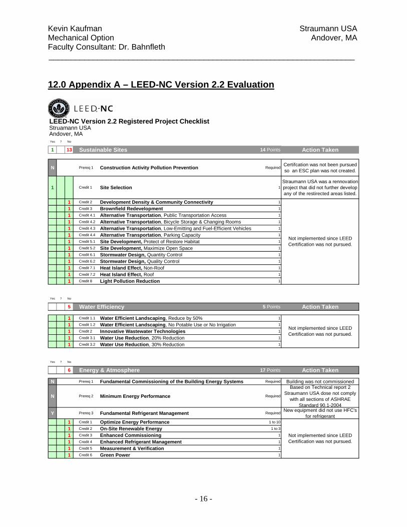
12.0 Appendix A – LEED-NC Version 2.2 Evaluation
LEED-NC Version 2.2 Registered Project Checklist
Yes ? No
1 13 Sustainable Sites 14 Points Action Taken
N Prereq 1 Construction Activity Pollution Prevention RequiredCertifcation was not been pursued so an ESC plan was not created.
1 Credit 1 Site Selection 1Straumann USA was a rennovation project that did not further develop any of the restirected areas listed.
1 Credit 2 Development Density & Community Connectivity 1
1 Credit 3 Brownfield Redevelopment 1
1 Credit 4.1 Alternative Transportation, Public Transportation Access 1
1 Credit 4.2 Alternative Transportation, Bicycle Storage & Changing Rooms 1
1 Credit 4.3 Alternative Transportation, Low-Emitting and Fuel-Efficient Vehicles 1
1 Credit 4.4 Alternative Transportation, Parking Capacity 1
1 Credit 5.1 Site Development, Protect of Restore Habitat 1
1 Credit 5.2 Site Development, Maximize Open Space 1
1 Credit 6.1 Stormwater Design, Quantity Control 1
1 Credit 6.2 Stormwater Design, Quality Control 1
1 Credit 7.1 Heat Island Effect, Non-Roof 1
1 Credit 7.2 Heat Island Effect, Roof 1
1 Credit 8 Light Pollution Reduction 1
Struamann USAAndover, MA
Not implemented since LEED Certification was not pursued.
Yes ? No
5 Water Efficiency 5 Points Action Taken
1 Credit 1.1 Water Efficient Landscaping, Reduce by 50% 1
1 Credit 1.2 Water Efficient Landscaping, No Potable Use or No Irrigation 1
1 Credit 2 Innovative Wastewater Technologies 1
1 Credit 3.1 Water Use Reduction, 20% Reduction 1
1 Credit 3.2 Water Use Reduction, 30% Reduction 1
Not implemented since LEED Certification was not pursued.
Yes ? No
6 Energy & Atmosphere 17 Points Action Taken
N Prereq 1 Fundamental Commissioning of the Building Energy Systems Required Building was not commissioned
N Prereq 2 Minimum Energy Performance Required
Based on Technical report 2 Straumann USA dose not comply
with all sections of ASHRAE Standard 90.1-2004
Y Prereq 3 Fundamental Refrigerant Management Required New equipment did not use HFC's for refrigerant
1 Credit 1 Optimize Energy Performance 1 to 10
1 Credit 2 On-Site Renewable Energy 1 to 3
1 Credit 3 Enhanced Commissioning 1
1 Credit 4 Enhanced Refrigerant Management 1
1 Credit 5 Measurement & Verification 1
1 Credit 6 Green Power 1
Not implemented since LEED Certification was not pursued.
Kevin Kaufman Straumann USA Mechanical Option Andover, MA Faculty Consultant: Dr. Bahnfleth _____________________________________________________________________
- 17 -
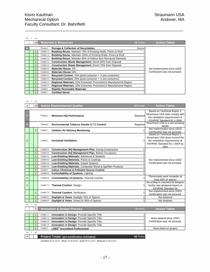
Yes ? No
13 Materials & Resources 13 Points Action Taken
N Prereq 1 Storage & Collection of Recyclables Required
1 Credit 1.1 Building Reuse, Maintain 75% of Existing Walls, Floors & Roof 1
1 Credit 1.2 Building Reuse, Maintain 100% of Existing Walls, Floors & Roof 1
1 Credit 1.3 Building Reuse, Maintain 50% of Interior Non-Structural Elements 1
1 Credit 2.1 Construction Waste Management, Divert 50% from Disposal 1
1 Credit 2.2 Construction Waste Management, Divert 75% from Disposal 1
1 Credit 3.1 Materials Reuse, 5% 1
1 Credit 3.2 Materials Reuse,10% 1
1 Credit 4.1 Recycled Content, 10% (post-consumer + ½ pre-consumer) 1
1 Credit 4.2 Recycled Content, 20% (post-consumer + ½ pre-consumer) 1
1 Credit 5.1 Regional Materials, 10% Extracted, Processed & Manufactured Regiona 1
1 Credit 5.2 Regional Materials, 20% Extracted, Processed & Manufactured Regiona 1
1 Credit 6 Rapidly Renewable Materials 1
1 Credit 7 Certified Wood 1
Not implemented since LEED Certification was not pursued.
Yes ? No
3 12 Indoor Environmental Quality 15 Points Action Taken
Y Prereq 1 Minimum IAQ Performance Required
Based on Technical Report 1 Straumann USA does comply with
the ventilation requirements of ASHRAE Standard 62.1-2004
Y Prereq 2 Environmental Tobacco Smoke (ETS) Control Required Straumann USA is a non-smoking facility
1 Credit 1 Outdoor Air Delivery Monitoring 1 Not implemented since LEED Certification was not pursued.
1 Credit 2 Increased Ventilation 1
Based on Technical Report 1 Straumann USA does exceed the
the ventilation requirements of ASHRAE Standard 62.1-2004 by
30%1 Credit 3.1 Construction IAQ Management Plan, During Construction 11 Credit 3.2 Construction IAQ Management Plan, Before Occupancy 11 Credit 4.1 Low-Emitting Materials, Adhesives & Sealants 11 Credit 4.2 Low-Emitting Materials, Paints & Coatings 11 Credit 4.3 Low-Emitting Materials, Carpet Systems 11 Credit 4.4 Low-Emitting Materials, Composite Wood & Agrifiber Products 11 Credit 5 Indoor Chemical & Pollutant Source Control 11 Credit 6.1 Controllability of Systems, Lighting 1
1 Credit 6.2 Controllability of Systems, Thermal Comfort 1 Thermostats were locatedin at least 50% of spaces
1 Credit 7.1 Thermal Comfort, Design 1According to mechanical designer
facility was designed based on ASHRAE Standard 55
1 Credit 7.2 Thermal Comfort, Verification 1 Not implemented since LEED Certification was not pursued.
1 Credit 8.1 Daylight & Views, Daylight 75% of Spaces 1 Not Attained1 Credit 8.2 Daylight & Views, Views for 90% of Spaces 1 Not Attained
Yes ? No
5 Innovation & Design Process 5 Points Action Taken
1 Credit 1.1 Innovation in Design: Provide Specific Title 1
1 Credit 1.2 Innovation in Design: Provide Specific Title 1
1 Credit 1.3 Innovation in Design: Provide Specific Title 1
1 Credit 1.4 Innovation in Design: Provide Specific Title 1
1 Credit 2 LEED® Accredited Professional 1 None listed on projectYes ? No
4 54 Project Totals (pre-certification estimates) 69 Points
Certified 26-32 points Silver 33-38 points Gold 39-51 points Platinum 52-69 points
None awared since LEED Certification was not pursued.
Not implemented since LEED Certification was not pursued.

Kevin Kaufman Straumann USA Mechanical Option Andover, MA Faculty Consultant: Dr. Bahnfleth _____________________________________________________________________
- 18 -
13.0 Appendix B – Space by Space Lighting Power Density Calculations Space Name Lamp
TypeNumber of
FixturesLamps per
Fixture Lamp Watts Ballast Factor Watts AREA POWER DENSITY AREA TYPE
MAX POWER DENSITY SPACE
BY SPACE
ACTUAL LIGHTING
POWER DENSITY
SPACE BY SPACE
COMPLIANCE
Manufacturing pmh1 67 1 400 1.08 28944 21128 MANUFACTURING 1.2 1.76 NOManufacturing pmh2 19 1 400 1.08 8208 21128 MANUFACTURINGPrototyping & Engin. Workshop pmh1 4 1 400 1.08 1728 2299 MANUFACTURING 1.2 1.13 YESPrototyping & Engin. Workshop pmh2 2 1 400 1.08 864 2299 MANUFACTURINGOffice rf2 7 3 32 1.08 725.76 782 OFFICE - ENCLOSED 1.1 0.93 YESCorridor rf2 2 3 32 1.08 207.36 131 CORRIDOR/TRANISTION 0.5 1.58 NOMeeting Room rf2 4 3 32 1.08 414.72 272 CONFERENCE 1.3 1.52 NOMeeting Room rf2 4 3 32 1.08 414.72 264 CONFERENCE 1.3 1.57 NOTel/Data RF16 3 2 32 1.08 207.36 263 ELECTRICAL/MECHANICAL 1.5 0.79 YESOil Storage SMH1 12 1 100 1.08 1296 776 ACTIVE STORAGE 0.8 1.76 NOOil Storage SF4 1 2 32 1.08 69.12 776 ACTIVE STORAGEShipping Dock SF1 9 2 32 1.08 622.08 587 MANUFACTURING 1.2 1.06 YESReceiving Office RF2 2 3 32 1.08 207.36 248 OFFICE - ENCLOSED 1.1 1.67 NOReceiving Office RF2 2 3 32 1.08 207.36 248 OFFICE - ENCLOSEDTrash SF1 6 2 32 1.08 414.72 361 ACTIVE STORAGE 0.8 1.72 NOTrash rf2 2 3 32 1.08 207.36 361 ACTIVE STORAGEAcid Storage SMH1 7 1 100 1.08 756 262 ACTIVE STORAGE 0.8 3.15 NOAcid Storage SF4 1 2 32 1.08 69.12 262 ACTIVE STORAGEReceiving Dock SF1 12 2 32 1.08 829.44 841 MANUFACTURING 1.2 0.99 YESEntry Vestibule RF2 3 3 32 1.08 311.04 324 LOBBY 1.3 0.96 YESMen's Locker RF18 31 1 32 1.08 1071.36 826 LOCKER ROOM 0.6 1.30 NOWomen's Locker RF18 24 1 32 1.08 829.44 761 LOCKER ROOM 0.6 1.09 NOMCC RF16 5 2 32 1.08 345.6 347 MANUFACTURING 1.2 1.00 YESTrovalistion RF2 6 3 32 1.08 622.08 659 MANUFACTURING 1.2 0.94 YESSand Blasting RF2 3 3 32 1.08 311.04 308 MANUFACTURING 1.2 1.01 YESWashing RF2 9 3 32 1.08 933.12 920 MANUFACTURING 1.2 1.01 YESClean Room SF1 4 2 32 1.08 276.48 1885 LABORATORY 1.4 0.15 YESStorage SF1 1 2 32 1.08 69.12 300 ACTIVE STORAGE 0.8 0.23 YESSand Blasting SF1 1 2 32 1.08 69.12 253 MANUFACTURING 1.2 0.27 YESCorridor RF2 5 3 32 1.08 518.4 469 CORRIDOR/TRANISTION 0.5 1.11 NOPurified Water RF16 8 2 32 1.08 552.96 427 MANUFACTURING 1.2 1.29 NOFinal Washing RF2 4 3 32 1.08 414.72 296 MANUFACTURING 1.2 1.40 NOStorage RF16 8 2 32 1.08 552.96 571 ACTIVE STORAGE 0.8 0.97 NOLocker Room RF16 2 2 32 1.08 138.24 173 LOCKER ROOM 0.6 0.80 NOOffice RF2 2 3 32 1.08 207.36 167 OFFICE - ENCLOSED 1.1 1.24 NOOffice RF2 2 3 32 1.08 207.36 167 OFFICE - ENCLOSED 1.1 1.24 NOPromotional Storage RF2 2 3 32 1.08 207.36 248 MANUFACTURING 1.2 0.84 YESCorridor RF2 8 3 32 1.08 829.44 984 CORRIDOR/TRANISTION 0.5 0.84 NOAir Lock RF2 1 3 32 1.08 103.68 114 CORRIDOR/TRANISTION 0.5 0.91 NOOpen Measurement RF2 4 3 32 1.08 414.72 412 MANUFACTURING 1.2 1.01 YESMeasurement Dev. Mgt. RF2 4 3 32 1.08 414.72 393 MANUFACTURING 1.2 1.06 YESMeasurement RF2 1 3 32 1.08 103.68 117 MANUFACTURING 1.2 0.89 YESQuality Assurance RF2 11 3 32 1.08 1140.48 1158 MANUFACTURING 1.2 0.98 YES

Kevin Kaufman Straumann USA Mechanical Option Andover, MA Faculty Consultant: Dr. Bahnfleth ________________________________________________________________________________________________
- 19 -
Space Name Lamp Type
Number of Fixtures
Lamps per Fixture Lamp Watts Ballast Factor Watts AREA POWER DENSITY AREA
TYPE
MAX POWER DENSITY SPACE
BY SPACE
ACTUAL LIGHTING
POWER DENSITY
SPACE BY SPACE
COMPLIANCE
Open Tools RF2 4 3 32 1.08 414.72 413 MANUFACTURING 1.2 1.00 YESTools Mgmt. RF2 4 3 32 1.08 414.72 393 MANUFACTURING 1.2 1.06 YESCorridor RF2 7 3 32 1.08 725.76 861 CORRIDOR/TRANISTION 0.5 0.84 NOAir Lock RF2 1 3 32 1.08 103.68 114 CORRIDOR/TRANISTION 0.5 0.91 NOCorridor rf2 8 3 32 1.08 829.44 932 CORRIDOR/TRANISTION 0.5 0.89 NOJanitor sf1 3 2 32 1.08 207.36 194 ACTIVE STORAGE 0.8 1.07 NOLife Safety SF1 1 2 32 1.08 69.12 41 ACTIVE STORAGE 0.8 1.69 NOCorridor pf11 1 4 18 1.08 77.76 164 CORRIDOR/TRANISTION 0.5 0.47 YESSecondary Manuf. Oper. rf2 20 3 32 1.08 2073.6 1947 MANUFACTURING 1.2 1.07 YESLaser Engrav. rf2 4 3 32 1.08 414.72 417 MANUFACTURING 1.2 0.99 YESControl Robot RF16 4 2 32 1.08 276.48 367 MANUFACTURING 1.2 1.88 NOControl Robot rf2 4 3 32 1.08 414.72 367 MANUFACTURING 1.2Open Office rf2 15 3 32 1.08 1555.2 1302 OFFICE - OPEN PLAN 1.1 1.19 NOMeeting Room rf2 6 3 32 1.08 622.08 393 CONFERENCE 1.3 1.58 NOStorage rf16 2 2 32 1.08 138.24 140 ACTIVE STORAGE 0.8 0.99 NOCoffee Station rf2 4 3 32 1.08 414.72 352 OFFICE - ENCLOSED 1.1 1.18 NOStorage RF16 20 2 32 1.08 1382.4 1520 ACTIVE STORAGE 0.8 0.91 NOStorage SF1 1 2 32 1.08 69.12 41 ACTIVE STORAGE 0.8 1.69 NOOffice RF2 2 3 32 1.08 207.36 165 OFFICE - ENCLOSED 1.1 1.26 NOOffice rf16 4 2 32 1.08 276.48 246 OFFICE - ENCLOSED 1.1 1.12 NOMeeting Room rf16 4 2 32 1.08 276.48 240 CONFERENCE 1.3 1.15 YESMeeting Room fm2 3 1 150 1.08 486 464 CONFERENCE 1.3 1.05 YESAlcove rf9 3 2 26 1.08 168.48 312 LOBBY 1.3 0.54 YESCorridor sf11 1 2 32 1.08 69.12 319 CORRIDOR/TRANISTION 0.5 0.22 YESCorridor wm4 2 LED 1 0 319 CORRIDOR/TRANISTIONFirst Aid rf2 4 3 32 1.08 414.72 290 NURSE STATION 0.8 1.43 NOAlcove rf2 4 3 32 1.08 414.72 361 LOBBY 1.3 1.15 YESCorridor rf2 4 3 32 1.08 414.72 260 CORRIDOR/TRANISTION 0.5 1.60 NOMail rf16 4 2 32 1.08 276.48 212 OFFICE - ENCLOSED 1.1 1.30 NOPrint Room rf2 6 3 32 1.08 622.08 315 OFFICE - ENCLOSED 1.1 1.97 NOServer Room rf15 3 3 32 1.08 311.04 556 ELECTRICAL/MECHANICAL 1.5 0.56 YESServer Room rf2 6 3 32 1.08 622.08 556 ELECTRICAL/MECHANICAL 1.5 1.12 YESTel/Data sf1 3 2 32 1.08 207.36 167 ELECTRICAL/MECHANICAL 1.5 1.24 YESElecrtric Room sf1 3 2 32 1.08 207.36 146 ACTIVE STORAGE 0.8 1.42 NOCorridor rf2 1 3 32 1.08 103.68 97 CORRIDOR/TRANISTION 0.5 1.07 NOCoats/Luggage rf2 3 3 32 1.08 311.04 274 ACTIVE STORAGE 0.8 1.14 NOCorridor pf11 6 4 18 1.08 466.56 275 CORRIDOR/TRANISTION 0.5 1.70 NODressing rf2 2 3 32 1.08 207.36 160 PATIENT ROOM 0.7 1.30 NODiagnostic Business Office rf3 2 3 32 1.08 207.36 191 OFFICE - ENCLOSED 1.1 1.09 YESToilet rf2 1 3 32 1.08 103.68 43 RESTROOMS 0.9 2.41 NORecovery rf2 1 3 32 1.08 103.68 104 PATIENT ROOM 0.7 1.00 NOCorridor rf2 4 3 32 1.08 414.72 325 CORRIDOR/TRANISTION 0.5 1.28 NODiagnostic rf3 2 3 32 1.08 207.36 206 PATIENT ROOM 0.7 1.01 NO

Kevin Kaufman Straumann USA Mechanical Option Andover, MA Faculty Consultant: Dr. Bahnfleth ________________________________________________________________________________________________
- 20 -
Space Name Lamp Type
Number of Fixtures
Lamps per Fixture Lamp Watts Ballast Factor Watts AREA POWER DENSITY AREA
TYPE
MAX POWER DENSITY SPACE
BY SPACE
ACTUAL LIGHTING
POWER DENSITY
SPACE BY SPACE
COMPLIANCE
Vacuum Pump room rf2 1 3 32 1.08 103.68 74 OPERATING ROOM 2.2 1.40 YESDiagnostic Xray rf2 2 3 32 1.08 207.36 97 PATIENT ROOM 0.7 2.14 NOConsultation Office rf3 2 3 32 1.08 207.36 208 OFFICE - ENCLOSED 1.1 1.00 YESMeeting Room rf22 12 3 32 1.08 1244.16 1000 CONFERENCE 1.3 1.24 YESCorridor rf2 3 3 32 1.08 311.04 280 CORRIDOR/TRANISTION 0.5 1.11 NOClean Sterilization rf2 2 3 32 1.08 207.36 97 EXAM/TREATMENT 1.5 2.14 NODental Operatory rf21 2 3 32 1.08 207.36 233 OPERATING ROOM 2.2 0.89 YESReading Room rf3 2 3 32 1.08 207.36 147 OFFICE - ENCLOSED 1.1 1.41 NOClean Sterilization rf2 2 3 32 1.08 207.36 97 EXAM/TREATMENT 1.5 2.14 NODental Operatory rf21 2 3 32 1.08 207.36 237 OPERATING ROOM 2.2 0.87 YESCorridor RF2 3 3 32 1.08 311.04 269 CORRIDOR/TRANISTION 0.5 1.16 NOMeeting Room RF2 4 3 32 1.08 414.72 145 CONFERENCE 1.3 2.86 NOTank Stor. 1 SF1 1 2 32 1.08 69.12 16 ACTIVE STORAGE 0.8 4.32 NOTech RF2 9 3 32 1.08 933.12 560 OFFICE - ENCLOSED 1.1 1.67 NOStorage RF16 4 2 32 1.08 276.48 285 ACTIVE STORAGE 0.8 0.97 NOCorridor RF2 3 3 32 1.08 311.04 236 CORRIDOR/TRANISTION 0.5 1.32 NOPrep RF3 9 3 32 1.08 933.12 580 NURSE STATION 0.8 1.61 NOTank Stor. 2 SF1 1 2 32 1.08 69.12 22 ACTIVE STORAGE 0.8 3.14 NOCasting RF2 2 3 32 1.08 207.36 154 MANUFACTURING 1.2 1.35 NOSimulation Lab RF3 30 3 32 1.08 3110.4 1750 OFFICE - ENCLOSED 1.1 1.78 NOCorridor RF2 3 3 32 1.08 311.04 311 CORRIDOR/TRANISTION 0.5 1.00 NOStorage RF2 2 3 32 1.08 207.36 130 ACTIVE STORAGE 0.8 1.60 NOCorridor RF9 2 2 26 1.08 112.32 115 CORRIDOR/TRANISTION 0.5 0.98 NOAuditorium RF9 38 2 26 1.08 2134.08 1760 AUDIENCE/SEATING AREA 0.9 1.91 NOAuditorium RF12 27 1 42 1.08 1224.72 1760 AUDIENCE/SEATING AREAControl Room RF2 2 3 32 1.08 207.36 153 CONROL ROOM 0.5 1.36 NOPantry RF-2 2 3 32 1.08 207.36 181 OFFICE - ENCLOSED 1.1 1.15 NOStor. Lit. rf16 2 2 32 1.08 138.24 122 ACTIVE STORAGE 0.8 1.13 NOEvents Coord. rf2 9 3 32 1.08 933.12 750 OFFICE - ENCLOSED 1.1 1.24 NORaw Material Stock & Prep PMH1 3 1 400 1.08 1296 1221 MANUFACTURING 1.2 1.42 NORaw Material Stock & Prep PMH2 1 1 400 1.08 432 1221 MANUFACTURINGMain Lobby FM1 2 1 150 1.08 324 2293 LOBBY 1.3 0.77 YESMain Lobby PMH3 1 1 150 1.08 162 2293 LOBBYMain Lobby RF20 6 2 42 1.08 544.32 2293 LOBBYMain Lobby rf7 6 1 50 1.08 324 2293 LOBBYMain Lobby sf11 6 2 32 1.08 414.72 2293 LOBBYOpen Office rf2 17 3 32 1.08 1762.56 1253 OFFICE - OPEN PLAN 1.1 1.41 NOCorridor rf10 21 2 42 1.08 1905.12 1515 CORRIDOR/TRANISTION 0.5 1.89 NOCorridor sf11 13 2 32 1.08 898.56 1515 CORRIDOR/TRANISTIONCorridor rf9 1 2 26 1.08 56.16 1515 CORRIDOR/TRANISTION

Kevin Kaufman Straumann USA Mechanical Option Andover, MA Faculty Consultant: Dr. Bahnfleth ________________________________________________________________________________________________
- 21 -
Space Name Lamp Type
Number of Fixtures
Lamps per Fixture Lamp Watts Ballast Factor Watts AREA POWER DENSITY AREA
TYPE
MAX POWER DENSITY SPACE
BY SPACE
ACTUAL LIGHTING
POWER DENSITY
SPACE BY SPACE
COMPLIANCE
Corridor rf2 6 3 32 1.08 622.08 1515 CORRIDOR/TRANISTION 0.5 0.41 YESCorridor pf6 3 1 200 1 600 6956 LOBBY 1.3 1.36 NOCorridor rf13 8 1 75 1 600 6956 LOBBYCorridor rf9 23 2 26 1.08 1291.68 6956 LOBBYCorridor rl2 12 3 75 1.08 2916 6956 LOBBYCorridor sf11 5 2 32 1.08 345.6 6956 LOBBYCorridor wm2 23 1 150 1.08 3726 6956 LOBBYCorridor wm4 6 LED 1 0 6956 LOBBYCorridor RF2 14 3 32 1.08 1451.52 1658 CORRIDOR/TRANISTION 0.5 0.88 NOPackaging RF2 89 3 32 1.08 9227.52 6470 MANUFACTURING 1.2 1.43 NOBoard Room RL1 4 4 75 1.08 1296 553 CONFERENCE 1.3 3.34 NOBoard Room RI1 11 1 50 1 550 553 CONFERENCEReception PF5 1 2 35 1.08 75.6 1187 LOBBY 1.3 1.49 NOReception RF10 2 2 42 1.08 181.44 1187 LOBBYReception RF9 2 2 26 1.08 112.32 1187 LOBBYReception RI2 2 1 50 1 100 1187 LOBBYReception RL2 4 3 75 1.08 972 1187 LOBBYReception RL3 11 1 28 1.08 332.64 1187 LOBBYReception RL3 1 28 1.08 0 1187 LOBBYChariman Office PF5 2 2 35 1.08 151.2 274 OFFICE - ENCLOSED 1.1 0.93 YESChariman Office RF18 3 1 32 1.08 103.68 274 OFFICE - ENCLOSEDCOO Office PF5 2 2 35 1.08 151.2 275 OFFICE - ENCLOSED 1.1 0.93 YESCOO Office RF18 3 1 32 1.08 103.68 275 OFFICE - ENCLOSEDAdministrative PF5 2 2 35 1.08 151.2 272 OFFICE - ENCLOSED 1.1 0.94 YESAdministrative RF18 3 1 32 1.08 103.68 272 OFFICE - ENCLOSEDCEO Office PF5 3 2 35 1.08 226.8 542 OFFICE - ENCLOSED 1.1 1.15 NOCEO Office RF11 2 1 50 1 100 542 OFFICE - ENCLOSEDCEO Office RF24 7 1 32 1.08 241.92 542 OFFICE - ENCLOSEDCEO Office RF7 1 1 50 1.08 54 542 OFFICE - ENCLOSEDPantry RF16 2 2 32 1.08 138.24 108 OFFICE - ENCLOSED 1.1 2.06 NOPantry UC1 3 2 13 1.08 84.24 108 OFFICE - ENCLOSEDLegal Office RF21 2 3 32 1.08 207.36 172 OFFICE - ENCLOSED 1.1 1.61 NOLegal Office RF18 2 1 32 1.08 69.12 172 OFFICE - ENCLOSEDVP office RF21 2 3 32 1.08 207.36 172 OFFICE - ENCLOSED 1.1 1.61 NOVP office RF18 2 1 32 1.08 69.12 172 OFFICE - ENCLOSEDVP office RF21 2 3 32 1.08 207.36 172 OFFICE - ENCLOSED 1.1 1.61 NOVP office RF18 2 1 32 1.08 69.12 172 OFFICE - ENCLOSEDCopy/Equipment RF2 2 3 32 1.08 207.36 156 OFFICE - ENCLOSED 1.1 1.33 NOCorridor PF2 162 1 54 1.08 9447.84 17275 OFFICE - OPEN PLAN 1.1 0.55 YESMeeting Room PF1 2 4 54 1.08 466.56 357 CONFERENCE 1.3 1.31 NOCoats RF16 2 2 32 1.08 138.24 148 ACTIVE STORAGE 0.8 0.93 NOOffice PF1 1 4 54 1.08 233.28 164 OFFICE - ENCLOSED 1.1 1.42 NOOffice PF1 1 4 54 1.08 233.28 164 OFFICE - ENCLOSED 1.1 1.42 NOOperations Manager Office PF10 1 6 54 1.08 349.92 198 OFFICE - ENCLOSED 1.1 1.77 NOAccounting Office PF10 1 6 54 1.08 349.92 198 OFFICE - ENCLOSED 1.1 1.77 NO

Kevin Kaufman Straumann USA Mechanical Option Andover, MA Faculty Consultant: Dr. Bahnfleth ________________________________________________________________________________________________
- 22 -
Space Name Lamp Type
Number of Fixtures
Lamps per Fixture Lamp Watts Ballast Factor Watts AREA POWER DENSITY AREA
TYPE
MAX POWER DENSITY SPACE
BY SPACE
ACTUAL LIGHTING
POWER DENSITY
SPACE BY SPACE
COMPLIANCE
Office PF1 1 4 54 1.08 233.28 162 OFFICE - ENCLOSED 1.1 1.44 NOElectric Room SF1 3 2 32 1.08 207.36 135 ACTIVE STORAGE 0.8 1.54 NOCoffee Area PF12 3 1 18 1.08 58.32 326 LOBBY 1.3 0.18 YESCoffee Area UC1 4 2 13 1.08 112.32 326 LOBBY 1.3 0.34 YESCoats RF2 1 3 32 1.08 103.68 70 ACTIVE STORAGE 0.8 1.48 NOCopy/Equipment RF2 5 3 32 1.08 518.4 256 OFFICE - ENCLOSED 1.1 2.30 NOCopy/Equipment RF4 1 2 32 1.08 69.12 256 OFFICE - ENCLOSEDStorage RF2 2 3 32 1.08 207.36 150 ACTIVE STORAGE 0.8 2.51 NOStorage RF9 3 2 26 1.08 168.48 150 ACTIVE STORAGETele/Data RF16 4 2 32 1.08 276.48 189 ELECTRICAL/MECHANICAL 1.5 1.46 YESOffice PF10 1 6 54 1.08 349.92 213 OFFICE - ENCLOSED 1.1 1.64 NOOffice PF1 1 4 54 1.08 233.28 169 OFFICE - ENCLOSED 1.1 1.38 NOOffice PF1 1 4 54 1.08 233.28 169 OFFICE - ENCLOSED 1.1 1.38 NOOffice PF1 1 4 54 1.08 233.28 169 OFFICE - ENCLOSED 1.1 1.38 NOOffice PF1 1 4 54 1.08 233.28 169 OFFICE - ENCLOSED 1.1 1.38 NOOffice PF1 1 4 54 1.08 233.28 165 OFFICE - ENCLOSED 1.1 1.41 NOOffice PF1 1 4 54 1.08 233.28 166 OFFICE - ENCLOSED 1.1 1.41 NOOffice PF1 1 4 54 1.08 233.28 166 OFFICE - ENCLOSED 1.1 1.41 NOMeeting Room PF10 1 6 54 1.08 349.92 179 CONFERENCE 1.3 1.95 NOMeeting Room PF1 2 4 54 1.08 466.56 263 CONFERENCE 1.3 1.77 NOCorridor RF2 3 3 32 1.08 311.04 827 CORRIDOR/TRANISTION 0.5 0.38 YESCorridor RF16 8 2 32 1.08 552.96 827 CORRIDOR/TRANISTION 0.5 0.67 NOServer Room RF16 3 2 32 1.08 207.36 528 ELECTRICAL/MECHANICAL 1.5 1.18 YESServer Room RF17 6 2 32 1.08 414.72 528 ELECTRICAL/MECHANICALMER RF9 8 2 26 1.08 449.28 268 ELECTRICAL/MECHANICAL 1.5 1.68 NOSTAIR wm5 1 6 32 1.08 207.36 197 STAIRS - ACTIVE 0.6 1.05 NOSE Men SF5 7 2 32 1.08 483.84 262 RESTROOMS 0.9 2.49 NOSE Men RF9 3 2 26 1.08 168.48 262 RESTROOMSSE Women SF5 7 2 32 1.08 483.84 240 RESTROOMS 0.9 2.72 NOSE Women RF9 3 2 26 1.08 168.48 240 RESTROOMSNW Men RF9 5 2 26 1.08 280.8 308 RESTROOMS 0.9 2.93 NONW Men SF5 9 2 32 1.08 622.08 308 RESTROOMSNW Women SF5 9 2 32 1.08 622.08 332 RESTROOMS 0.9 2.72 NONW Women RF9 5 2 26 1.08 280.8 332 RESTROOMSJanitor SF1 1 2 32 1.08 69.12 42 ACTIVE STORAGE 0.8 1.65 NOMen's Shower RF14 4 1 32 1.08 138.24 311 LOCKER ROOM 0.6 0.99 NOMen's Shower RF9 3 2 26 1.08 168.48 311 LOCKER ROOMWomen's Shower RF14 2 1 32 1.08 69.12 248 LOCKER ROOM 0.6 0.73 NOWomen's Shower RF9 2 2 26 1.08 112.32 248 LOCKER ROOM

Kevin Kaufman Straumann USA Mechanical Option Andover, MA Faculty Consultant: Dr. Bahnfleth ________________________________________________________________________________
- 23 -
14.0 Appendix C – HAP System Sizing Air System Sizing Summary for RTU-1
Air System Information Air System Name ............................................... RTU-1 Equipment Class ........................................... CW AHU Air System Type .................................................... VAV
Number of zones .......................................................... 32 Floor Area ............................................................ 25072.0 ft² Location .................................... Boston, Massachusetts
Sizing Calculation Information Zone and Space Sizing Method:
Zone CFM ........................... Peak zone sensible load Space CFM ................... Individual peak space loads
Calculation Months ......................................... Jan to Dec Sizing Data ..................................................... Calculated
Central Cooling Coil Sizing Data
Total coil load ........................................................ 93.2 Tons Total coil load .................................................... 1118.6 MBH Sensible coil load ................................................ 845.2 MBH Coil CFM at Jul 1500 .......................................... 19651 CFM Max block CFM at Jun 1600 .............................. 20151 CFM Sum of peak zone CFM ..................................... 20151 CFM Sensible heat ratio .............................................. 0.756 ft²/Ton .................................................................. 269.0 BTU/(hr-ft²) ............................................................ 44.6 Water flow @ 10.0 °F rise ................................. 223.84 gpm
Load occurs at .................................................... Jul 1500 OA DB / WB ..................................................... 90.3 / 73.0 °F Entering DB / WB ............................................ 91.6 / 69.2 °F Leaving DB / WB ............................................. 51.7 / 49.9 °F Coil ADP .................................................................... 47.3 °F Bypass Factor .......................................................... 0.100 Resulting RH ................................................................ 37 % Design supply temp. .................................................. 55.0 °F Zone T-stat Check .............................................. 31 of 32 OK Max zone temperature deviation ................................. 0.2 °F
Preheat Coil Sizing Data
Max coil load ....................................................... 201.4 MBH Coil CFM at Des Htg ............................................ 3946 CFM Max coil CFM ....................................................... 8985 CFM Water flow @ 20.0 °F drop ..................................... N/A
Load occurs at .................................................... Des Htg Ent. DB / Lvg DB ............................................... 7.7 / 55.0 °F
Supply Fan Sizing Data
Actual max CFM at Jun 1600 ............................. 20151 CFM Standard CFM .................................................... 20129 CFM Actual max CFM/ft² ............................................... 0.80 CFM/ft²
Fan motor BHP ........................................................ 29.17 BHP Fan motor kW .......................................................... 21.75 kW Fan static ................................................................... 5.52 in wg
Return Fan Sizing Data
Actual max CFM at Jun 1600 ............................. 20151 CFM Standard CFM .................................................... 20129 CFM Actual max CFM/ft² ............................................... 0.80 CFM/ft²
Fan motor BHP .......................................................... 7.93 BHP Fan motor kW ............................................................ 5.91 kW Fan static ................................................................... 1.50 in wg
Outdoor Ventilation Air Data Design airflow CFM .............................................. 8985 CFM CFM/ft² .................................................................. 0.36 CFM/ft²
CFM/person ............................................................. 80.22 CFM/person

Kevin Kaufman Straumann USA Mechanical Option Andover, MA Faculty Consultant: Dr. Bahnfleth ________________________________________________________________________________
- 24 -
Air System Sizing Summary for RTU-2
Air System Information Air System Name ............................................... RTU-2 Equipment Class ........................................... CW AHU Air System Type .................................................... VAV
Number of zones .......................................................... 30 Floor Area ............................................................ 21761.0 ft² Location .................................... Boston, Massachusetts
Sizing Calculation Information Zone and Space Sizing Method:
Zone CFM ........................... Peak zone sensible load Space CFM ................... Individual peak space loads
Calculation Months ......................................... Jan to Dec Sizing Data ..................................................... Calculated
Central Cooling Coil Sizing Data
Total coil load ........................................................ 97.9 Tons Total coil load .................................................... 1174.4 MBH Sensible coil load ................................................ 775.0 MBH Coil CFM at Jul 1500 .......................................... 20059 CFM Max block CFM at Jul 1500 ................................ 20905 CFM Sum of peak zone CFM ..................................... 20941 CFM Sensible heat ratio .............................................. 0.660 ft²/Ton .................................................................. 222.4 BTU/(hr-ft²) ............................................................ 54.0 Water flow @ 10.0 °F rise ................................. 235.00 gpm
Load occurs at .................................................... Jul 1500 OA DB / WB ..................................................... 90.3 / 73.0 °F Entering DB / WB ............................................ 87.6 / 70.0 °F Leaving DB / WB ............................................. 51.8 / 50.5 °F Coil ADP .................................................................... 47.8 °F Bypass Factor .......................................................... 0.100 Resulting RH ................................................................ 41 % Design supply temp. .................................................. 55.0 °F Zone T-stat Check .............................................. 26 of 30 OK Max zone temperature deviation ................................. 0.4 °F
Preheat Coil Sizing Data
Max coil load ....................................................... 300.7 MBH Coil CFM at Des Htg ............................................ 5892 CFM Max coil CFM ..................................................... 13929 CFM Water flow @ 20.0 °F drop ..................................... N/A
Load occurs at .................................................... Des Htg Ent. DB / Lvg DB ............................................... 7.7 / 55.0 °F
Supply Fan Sizing Data
Actual max CFM at Jul 1500 .............................. 20905 CFM Standard CFM .................................................... 20883 CFM Actual max CFM/ft² ............................................... 0.96 CFM/ft²
Fan motor BHP ........................................................ 30.26 BHP Fan motor kW .......................................................... 22.56 kW Fan static ................................................................... 5.52 in wg
Return Fan Sizing Data
Actual max CFM at Jul 1500 .............................. 20905 CFM Standard CFM .................................................... 20883 CFM Actual max CFM/ft² ............................................... 0.96 CFM/ft²
Fan motor BHP .......................................................... 8.22 BHP Fan motor kW ............................................................ 6.13 kW Fan static ................................................................... 1.50 in wg
Outdoor Ventilation Air Data Design airflow CFM ............................................ 13929 CFM CFM/ft² .................................................................. 0.64 CFM/ft²
CFM/person ............................................................. 48.87 CFM/person

Kevin Kaufman Straumann USA Mechanical Option Andover, MA Faculty Consultant: Dr. Bahnfleth ________________________________________________________________________________
- 25 -
Air System Sizing Summary for RTU-3
Air System Information Air System Name ............................................... RTU-3 Equipment Class ........................................... CW AHU Air System Type ............................................... SZCAV
Number of zones ............................................................ 1 Floor Area .............................................................. 3928.0 ft² Location .................................... Boston, Massachusetts
Sizing Calculation Information Zone and Space Sizing Method:
Zone CFM ....................... Sum of space airflow rates Space CFM ................... Individual peak space loads
Calculation Months ......................................... Jan to Dec Sizing Data ..................................................... Calculated
Central Cooling Coil Sizing Data
Total coil load ........................................................ 21.6 Tons Total coil load ...................................................... 258.9 MBH Sensible coil load ................................................ 169.2 MBH Coil CFM at Jul 1400 ............................................ 4282 CFM Max block CFM .................................................... 4319 CFM Sum of peak zone CFM ....................................... 4319 CFM Sensible heat ratio .............................................. 0.654 ft²/Ton .................................................................. 182.1 BTU/(hr-ft²) ............................................................ 65.9 Water flow @ 7.0 °F rise ..................................... 74.00 gpm
Load occurs at .................................................... Jul 1400 OA DB / WB ..................................................... 89.1 / 72.6 °F Entering DB / WB ............................................ 90.1 / 71.6 °F Leaving DB / WB ............................................. 53.5 / 52.1 °F Coil ADP .................................................................... 49.4 °F Bypass Factor .......................................................... 0.100 Resulting RH ................................................................ 48 % Design supply temp. .................................................. 55.0 °F Zone T-stat Check .................................................. 1 of 1 OK Max zone temperature deviation ................................. 0.0 °F
Preheat Coil Sizing Data
Max coil load ......................................................... 41.3 MBH Coil CFM at Jan 0800 .......................................... 2248 CFM Max coil CFM ....................................................... 3071 CFM Water flow @ 20.0 °F drop ..................................... N/A
Load occurs at ................................................... Jan 0800 Ent. DB / Lvg DB ............................................. 38.0 / 55.0 °F
Supply Fan Sizing Data
Actual max CFM ................................................... 4319 CFM Standard CFM ...................................................... 4314 CFM Actual max CFM/ft² ............................................... 1.10 CFM/ft²
Fan motor BHP .......................................................... 2.80 BHP Fan motor kW ............................................................ 2.09 kW Fan static ................................................................... 2.47 in wg
Return Fan Sizing Data
Actual max CFM ................................................... 4319 CFM Standard CFM ...................................................... 4314 CFM Actual max CFM/ft² ............................................... 1.10 CFM/ft²
Fan motor BHP .......................................................... 1.13 BHP Fan motor kW ............................................................ 0.84 kW Fan static ................................................................... 1.00 in wg
Outdoor Ventilation Air Data Design airflow CFM .............................................. 3071 CFM CFM/ft² .................................................................. 0.78 CFM/ft²
CFM/person ............................................................. 20.33 CFM/person

Kevin Kaufman Straumann USA Mechanical Option Andover, MA Faculty Consultant: Dr. Bahnfleth ________________________________________________________________________________
- 26 -
Air System Sizing Summary for RTU-4
Air System Information Air System Name ............................................... RTU-4 Equipment Class ........................................... CW AHU Air System Type .................................................... VAV
Number of zones .......................................................... 37 Floor Area ............................................................ 22411.0 ft² Location .................................... Boston, Massachusetts
Sizing Calculation Information Zone and Space Sizing Method:
Zone CFM ........................... Peak zone sensible load Space CFM ................... Individual peak space loads
Calculation Months ......................................... Jan to Dec Sizing Data ..................................................... Calculated
Central Cooling Coil Sizing Data
Total coil load ........................................................ 99.0 Tons Total coil load .................................................... 1188.5 MBH Sensible coil load ................................................ 883.1 MBH Coil CFM at Aug 1500 ........................................ 23052 CFM Max block CFM at Aug 1500 .............................. 23301 CFM Sum of peak zone CFM ..................................... 24186 CFM Sensible heat ratio .............................................. 0.743 ft²/Ton .................................................................. 226.3 BTU/(hr-ft²) ............................................................ 53.0 Water flow @ 10.0 °F rise ................................. 237.82 gpm
Load occurs at .................................................. Aug 1500 OA DB / WB ..................................................... 90.3 / 73.0 °F Entering DB / WB ............................................ 87.1 / 67.8 °F Leaving DB / WB ............................................. 51.6 / 50.1 °F Coil ADP .................................................................... 47.7 °F Bypass Factor .......................................................... 0.100 Resulting RH ................................................................ 38 % Design supply temp. .................................................. 55.0 °F Zone T-stat Check .............................................. 35 of 37 OK Max zone temperature deviation ................................. 0.3 °F
Preheat Coil Sizing Data
Max coil load ....................................................... 197.4 MBH Coil CFM at Des Htg ............................................ 3868 CFM Max coil CFM ....................................................... 9636 CFM Water flow @ 20.0 °F drop ..................................... N/A
Load occurs at .................................................... Des Htg Ent. DB / Lvg DB ............................................... 7.7 / 55.0 °F
Supply Fan Sizing Data
Actual max CFM at Aug 1500 ............................ 23301 CFM Standard CFM .................................................... 23276 CFM Actual max CFM/ft² ............................................... 1.04 CFM/ft²
Fan motor BHP ........................................................ 33.73 BHP Fan motor kW .......................................................... 25.15 kW Fan static ................................................................... 5.52 in wg
Return Fan Sizing Data
Actual max CFM at Aug 1500 ............................ 23301 CFM Standard CFM .................................................... 23276 CFM Actual max CFM/ft² ............................................... 1.04 CFM/ft²
Fan motor BHP .......................................................... 7.09 BHP Fan motor kW ............................................................ 5.29 kW Fan static ................................................................... 1.16 in wg
Outdoor Ventilation Air Data Design airflow CFM .............................................. 9636 CFM CFM/ft² .................................................................. 0.43 CFM/ft²
CFM/person ............................................................. 47.70 CFM/person

Kevin Kaufman Straumann USA Mechanical Option Andover, MA Faculty Consultant: Dr. Bahnfleth ________________________________________________________________________________
- 27 -
Air System Sizing Summary for RTU-5
Air System Information Air System Name ............................................... RTU-5 Equipment Class ........................................... CW AHU Air System Type .................................................... VAV
Number of zones .......................................................... 15 Floor Area ............................................................ 10877.0 ft² Location .................................... Boston, Massachusetts
Sizing Calculation Information Zone and Space Sizing Method:
Zone CFM ........................... Peak zone sensible load Space CFM ................... Individual peak space loads
Calculation Months ......................................... Jan to Dec Sizing Data ..................................................... Calculated
Central Cooling Coil Sizing Data
Total coil load ........................................................ 70.7 Tons Total coil load ...................................................... 848.2 MBH Sensible coil load ................................................ 647.3 MBH Coil CFM at Jul 1500 .......................................... 14383 CFM Max block CFM at Jul 1500 ................................ 14625 CFM Sum of peak zone CFM ..................................... 15360 CFM Sensible heat ratio .............................................. 0.763 ft²/Ton .................................................................. 153.9 BTU/(hr-ft²) ............................................................ 78.0 Water flow @ 7.0 °F rise ................................... 242.46 gpm
Load occurs at .................................................... Jul 1500 OA DB / WB ..................................................... 90.3 / 73.0 °F Entering DB / WB ............................................ 91.7 / 68.6 °F Leaving DB / WB ............................................. 50.0 / 48.2 °F Coil ADP .................................................................... 45.4 °F Bypass Factor .......................................................... 0.100 Resulting RH ................................................................ 35 % Design supply temp. .................................................. 55.0 °F Zone T-stat Check .............................................. 11 of 15 OK Max zone temperature deviation ................................. 0.8 °F
Preheat Coil Sizing Data
Max coil load ....................................................... 125.6 MBH Coil CFM at Des Htg ............................................ 2461 CFM Max coil CFM ....................................................... 6040 CFM Water flow @ 20.0 °F drop ..................................... N/A
Load occurs at .................................................... Des Htg Ent. DB / Lvg DB ............................................... 7.7 / 55.0 °F
Supply Fan Sizing Data
Actual max CFM at Jul 1500 .............................. 14625 CFM Standard CFM .................................................... 14609 CFM Actual max CFM/ft² ............................................... 1.34 CFM/ft²
Fan motor BHP ........................................................ 31.52 BHP Fan motor kW .......................................................... 23.50 kW Fan static ................................................................... 5.89 in wg
Return Fan Sizing Data
Actual max CFM at Jul 1500 .............................. 14625 CFM Standard CFM .................................................... 14609 CFM Actual max CFM/ft² ............................................... 1.34 CFM/ft²
Fan motor BHP .......................................................... 5.75 BHP Fan motor kW ............................................................ 4.29 kW Fan static ................................................................... 1.50 in wg
Outdoor Ventilation Air Data Design airflow CFM .............................................. 6040 CFM CFM/ft² .................................................................. 0.56 CFM/ft²
CFM/person ............................................................. 69.43 CFM/person

Kevin Kaufman Straumann USA Mechanical Option Andover, MA Faculty Consultant: Dr. Bahnfleth ________________________________________________________________________________
- 28 -
Air System Sizing Summary for RTU-6
Air System Information Air System Name ............................................... RTU-6 Equipment Class ........................................... CW AHU Air System Type .................................................... VAV
Number of zones .......................................................... 12 Floor Area ............................................................ 14597.0 ft² Location .................................... Boston, Massachusetts
Sizing Calculation Information Zone and Space Sizing Method:
Zone CFM ........................... Peak zone sensible load Space CFM ................... Individual peak space loads
Calculation Months ......................................... Jan to Dec Sizing Data ..................................................... Calculated
Central Cooling Coil Sizing Data
Total coil load ........................................................ 79.0 Tons Total coil load ...................................................... 948.2 MBH Sensible coil load ................................................ 666.0 MBH Coil CFM at Jul 1500 .......................................... 15617 CFM Max block CFM at Jun 1500 .............................. 15718 CFM Sum of peak zone CFM ..................................... 15723 CFM Sensible heat ratio .............................................. 0.702 ft²/Ton .................................................................. 184.7 BTU/(hr-ft²) ............................................................ 65.0 Water flow @ 7.0 °F rise ................................... 271.05 gpm
Load occurs at .................................................... Jul 1500 OA DB / WB ..................................................... 90.3 / 73.0 °F Entering DB / WB ............................................ 91.6 / 70.6 °F Leaving DB / WB ............................................. 52.1 / 50.5 °F Coil ADP .................................................................... 47.7 °F Bypass Factor .......................................................... 0.100 Resulting RH ................................................................ 38 % Design supply temp. .................................................. 55.0 °F Zone T-stat Check .............................................. 11 of 12 OK Max zone temperature deviation ................................. 0.4 °F
Preheat Coil Sizing Data
Max coil load ....................................................... 175.6 MBH Coil CFM at Des Htg ............................................ 3441 CFM Max coil CFM ....................................................... 9657 CFM Water flow @ 20.0 °F drop ..................................... N/A
Load occurs at .................................................... Des Htg Ent. DB / Lvg DB ............................................... 7.7 / 55.0 °F
Supply Fan Sizing Data
Actual max CFM at Jun 1500 ............................. 15718 CFM Standard CFM .................................................... 15701 CFM Actual max CFM/ft² ............................................... 1.08 CFM/ft²
Fan motor BHP ........................................................ 19.50 BHP Fan motor kW .......................................................... 14.54 kW Fan static ................................................................... 5.52 in wg
Return Fan Sizing Data
Actual max CFM at Jun 1500 ............................. 15718 CFM Standard CFM .................................................... 15701 CFM Actual max CFM/ft² ............................................... 1.08 CFM/ft²
Fan motor BHP .......................................................... 5.30 BHP Fan motor kW ............................................................ 3.95 kW Fan static ................................................................... 1.50 in wg
Outdoor Ventilation Air Data Design airflow CFM .............................................. 9657 CFM CFM/ft² .................................................................. 0.66 CFM/ft²
CFM/person ........................................................... 101.65 CFM/person

Kevin Kaufman Straumann USA Mechanical Option Andover, MA Faculty Consultant: Dr. Bahnfleth ________________________________________________________________________________
- 29 -
Air System Sizing Summary for RTU-7,8,9,10 Air System Information Air System Name .................................... RTU-7,8,9,10 Equipment Class ........................................... CW AHU Air System Type .................................................... VAV
Number of zones ............................................................ 1 Floor Area ............................................................ 24222.0 ft² Location .................................... Boston, Massachusetts
Sizing Calculation Information Zone and Space Sizing Method:
Zone CFM ........................... Peak zone sensible load Space CFM ................... Individual peak space loads
Calculation Months ......................................... Jan to Dec Sizing Data ..................................................... Calculated
Central Cooling Coil Sizing Data
Total coil load ...................................................... 359.7 Tons Total coil load .................................................... 4316.6 MBH Sensible coil load .............................................. 4241.3 MBH Coil CFM at Jul 1600 ........................................ 131695 CFM Max block CFM at Aug 1600 ............................ 144860 CFM Sum of peak zone CFM ................................... 144860 CFM Sensible heat ratio .............................................. 0.983 ft²/Ton .................................................................... 67.3 BTU/(hr-ft²) .......................................................... 178.2 Water flow @ 7.0 °F rise ................................. 1233.96 gpm
Load occurs at .................................................... Jul 1600 OA DB / WB ..................................................... 90.8 / 73.1 °F Entering DB / WB ............................................ 81.9 / 62.2 °F Leaving DB / WB ............................................. 52.0 / 50.2 °F Coil ADP .................................................................... 48.7 °F Bypass Factor .......................................................... 0.100 Resulting RH ................................................................ 36 % Design supply temp. .................................................. 55.0 °F Zone T-stat Check .................................................. 1 of 1 OK Max zone temperature deviation ................................. 0.0 °F
Preheat Coil Sizing Data
Max coil load ......................................................... 31.3 MBH Coil CFM at Jan 0800 .......................................... 1708 CFM Max coil CFM ....................................................... 2094 CFM Water flow @ 48.0 °F drop ..................................... N/A
Load occurs at ................................................... Jan 0800 Ent. DB / Lvg DB ............................................. 38.0 / 55.0 °F
Supply Fan Sizing Data
Actual max CFM at Aug 1600 .......................... 144860 CFM Standard CFM .................................................. 144703 CFM Actual max CFM/ft² ............................................... 5.98 CFM/ft²
Fan motor BHP ...................................................... 209.67 BHP Fan motor kW ........................................................ 156.35 kW Fan static ................................................................... 5.52 in wg
Return Fan Sizing Data
Actual max CFM at Aug 1600 .......................... 144860 CFM Standard CFM .................................................. 144703 CFM Actual max CFM/ft² ............................................... 5.98 CFM/ft²
Fan motor BHP ........................................................ 56.98 BHP Fan motor kW .......................................................... 42.49 kW Fan static ................................................................... 1.50 in wg
Outdoor Ventilation Air Data Design airflow CFM .............................................. 2094 CFM CFM/ft² .................................................................. 0.09 CFM/ft²
CFM/person ............................................................. 25.23 CFM/person

Kevin Kaufman Straumann USA Mechanical Option Andover, MA Faculty Consultant: Dr. Bahnfleth ________________________________________________________________________________
- 30 -
Zone Sizing Summary for AC-1,2 Air System Information Air System Name .............................................. AC-1,2 Equipment Class ................................................ TERM Air System Type ............................................ SPLT-FC
Number of zones ............................................................ 1 Floor Area ................................................................ 556.0 ft² Location .................................... Boston, Massachusetts
Sizing Calculation Information Zone and Space Sizing Method: Zone CFM ....................... Sum of space airflow rates Space CFM ................... Individual peak space loads
Calculation Months ......................................... Jan to Dec Sizing Data ..................................................... Calculated
Zone Sizing Data
Maximum Design Minimum Time Maximum Zone Cooling Air Air of Heating Floor Sensible Flow Flow Peak Load Area ZoneZone Name (MBH) (CFM) (CFM) Load (MBH) (ft²) CFM/ft²Zone 1 108.7 5038 5038 Jan 0000 0.0 556.0 9.06
Terminal Unit Sizing Data - Cooling
Total Sens Coil Coil Water Time Coil Coil Entering Leaving Flow of Load Load DB / WB DB / WB @ 10.0 °F PeakZone Name (MBH) (MBH) (°F) (°F) (gpm) LoadZone 1 120.4 110.7 75.9 / 62.6 55.5 / 54.3 - Jan 2200
Terminal Unit Sizing Data - Heating, Fan, Ventilation
HEATING COIL SIZING DATA FAN SIZING DATA VENT Coil Water Coil Ent/Lvg Flow Design Fan Fan Design Load DB @20.0 °F Airflow Motor Motor AirflowZone Name (MBH) (°F) (gpm) (CFM) (BHP) (kW) (CFM)Zone 1 0.0 0.0 / 0.0 0.00 5038 0.793 0.591 0
Space Loads and Airflows
Cooling Time Air Heating Floor Zone Name / Sensible of Flow Load Area Space Space Name Mult. (MBH) Load (CFM) (MBH) (ft²) CFM/ft²Zone 1 119 Server Room ac-1,2 1 108.7 Jan 0000 5038 0.0 556.0 9.06
Kevin Kaufman Straumann USA Mechanical Option Andover, MA Faculty Consultant: Dr. Bahnfleth ________________________________________________________________________________
- 31 -
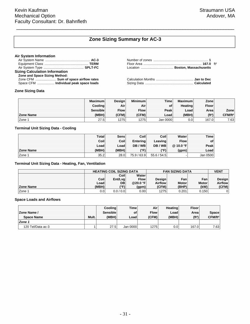
Zone Sizing Summary for AC-3 Air System Information Air System Name ................................................. AC-3 Equipment Class ................................................ TERM Air System Type ............................................ SPLT-FC
Number of zones ............................................................ 1 Floor Area ................................................................ 167.0 ft² Location .................................... Boston, Massachusetts
Sizing Calculation Information Zone and Space Sizing Method: Zone CFM ....................... Sum of space airflow rates Space CFM ................... Individual peak space loads
Calculation Months ......................................... Jan to Dec Sizing Data ..................................................... Calculated
Zone Sizing Data
Maximum Design Minimum Time Maximum Zone Cooling Air Air of Heating Floor Sensible Flow Flow Peak Load Area ZoneZone Name (MBH) (CFM) (CFM) Load (MBH) (ft²) CFM/ft²Zone 1 27.5 1275 1275 Jan 0000 0.0 167.0 7.63
Terminal Unit Sizing Data - Cooling
Total Sens Coil Coil Water Time Coil Coil Entering Leaving Flow of Load Load DB / WB DB / WB @ 10.0 °F PeakZone Name (MBH) (MBH) (°F) (°F) (gpm) LoadZone 1 35.2 28.0 75.9 / 63.9 55.6 / 54.5 - Jan 0500
Terminal Unit Sizing Data - Heating, Fan, Ventilation
HEATING COIL SIZING DATA FAN SIZING DATA VENT Coil Water Coil Ent/Lvg Flow Design Fan Fan Design Load DB @20.0 °F Airflow Motor Motor AirflowZone Name (MBH) (°F) (gpm) (CFM) (BHP) (kW) (CFM)Zone 1 0.0 0.0 / 0.0 0.00 1275 0.201 0.150 0
Space Loads and Airflows
Cooling Time Air Heating Floor Zone Name / Sensible of Flow Load Area Space Space Name Mult. (MBH) Load (CFM) (MBH) (ft²) CFM/ft²Zone 1 120 Tel/Data ac-3 1 27.5 Jan 0000 1275 0.0 167.0 7.63
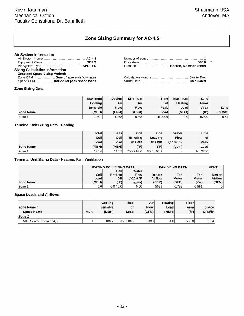
Kevin Kaufman Straumann USA Mechanical Option Andover, MA Faculty Consultant: Dr. Bahnfleth ________________________________________________________________________________
- 32 -
Zone Sizing Summary for AC-4,5 Air System Information Air System Name .............................................. AC-4,5 Equipment Class ................................................ TERM Air System Type ............................................ SPLT-FC
Number of zones ............................................................ 1 Floor Area ................................................................ 528.0 ft² Location .................................... Boston, Massachusetts
Sizing Calculation Information Zone and Space Sizing Method: Zone CFM ....................... Sum of space airflow rates Space CFM ................... Individual peak space loads
Calculation Months ......................................... Jan to Dec Sizing Data ..................................................... Calculated
Zone Sizing Data
Maximum Design Minimum Time Maximum Zone Cooling Air Air of Heating Floor Sensible Flow Flow Peak Load Area ZoneZone Name (MBH) (CFM) (CFM) Load (MBH) (ft²) CFM/ft²Zone 1 108.7 5038 5038 Jan 0000 0.0 528.0 9.54
Terminal Unit Sizing Data - Cooling
Total Sens Coil Coil Water Time Coil Coil Entering Leaving Flow of Load Load DB / WB DB / WB @ 10.0 °F PeakZone Name (MBH) (MBH) (°F) (°F) (gpm) LoadZone 1 120.4 110.7 75.9 / 62.6 55.5 / 54.3 - Jan 2300
Terminal Unit Sizing Data - Heating, Fan, Ventilation
HEATING COIL SIZING DATA FAN SIZING DATA VENT Coil Water Coil Ent/Lvg Flow Design Fan Fan Design Load DB @20.0 °F Airflow Motor Motor AirflowZone Name (MBH) (°F) (gpm) (CFM) (BHP) (kW) (CFM)Zone 1 0.0 0.0 / 0.0 0.00 5038 0.793 0.591 0
Space Loads and Airflows
Cooling Time Air Heating Floor Zone Name / Sensible of Flow Load Area Space Space Name Mult. (MBH) Load (CFM) (MBH) (ft²) CFM/ft²Zone 1 M45 Server Room ac4,5 1 108.7 Jan 0000 5038 0.0 528.0 9.54

Kevin Kaufman Straumann USA Mechanical Option Andover, MA Faculty Consultant: Dr. Bahnfleth ________________________________________________________________________________
- 33 -
Zone Sizing Summary for AC-6 Air System Information Air System Name ................................................. AC-6 Equipment Class ................................................ TERM Air System Type ............................................ SPLT-FC
Number of zones ............................................................ 1 Floor Area ................................................................ 528.0 ft² Location .................................... Boston, Massachusetts
Sizing Calculation Information Zone and Space Sizing Method: Zone CFM ....................... Sum of space airflow rates Space CFM ................... Individual peak space loads
Calculation Months ......................................... Jan to Dec Sizing Data ..................................................... Calculated
Zone Sizing Data
Maximum Design Minimum Time Maximum Zone Cooling Air Air of Heating Floor Sensible Flow Flow Peak Load Area ZoneZone Name (MBH) (CFM) (CFM) Load (MBH) (ft²) CFM/ft²Zone 1 27.5 1275 1275 Jan 0000 0.0 528.0 2.41
Terminal Unit Sizing Data - Cooling
Total Sens Coil Coil Water Time Coil Coil Entering Leaving Flow of Load Load DB / WB DB / WB @ 10.0 °F PeakZone Name (MBH) (MBH) (°F) (°F) (gpm) LoadZone 1 35.5 28.3 75.9 / 63.8 55.3 / 54.2 - Feb 1200
Terminal Unit Sizing Data - Heating, Fan, Ventilation
HEATING COIL SIZING DATA FAN SIZING DATA VENT Coil Water Coil Ent/Lvg Flow Design Fan Fan Design Load DB @20.0 °F Airflow Motor Motor AirflowZone Name (MBH) (°F) (gpm) (CFM) (BHP) (kW) (CFM)Zone 1 0.0 0.0 / 0.0 0.00 1275 0.201 0.150 0
Space Loads and Airflows
Cooling Time Air Heating Floor Zone Name / Sensible of Flow Load Area Space Space Name Mult. (MBH) Load (CFM) (MBH) (ft²) CFM/ft²Zone 1 M45 Server Room ac-6 1 27.5 Jan 0000 1275 0.0 528.0 2.41

Kevin Kaufman Straumann USA Mechanical Option Andover, MA Faculty Consultant: Dr. Bahnfleth ________________________________________________________________________________
- 34 -
Zone Sizing Summary for AC-7 Air System Information Air System Name ................................................. AC-7 Equipment Class ................................................ TERM Air System Type ............................................ SPLT-FC
Number of zones ............................................................ 1 Floor Area ................................................................ 268.0 ft² Location .................................... Boston, Massachusetts
Sizing Calculation Information Zone and Space Sizing Method: Zone CFM ....................... Sum of space airflow rates Space CFM ................... Individual peak space loads
Calculation Months ......................................... Jan to Dec Sizing Data ..................................................... Calculated
Zone Sizing Data
Maximum Design Minimum Time Maximum Zone Cooling Air Air of Heating Floor Sensible Flow Flow Peak Load Area ZoneZone Name (MBH) (CFM) (CFM) Load (MBH) (ft²) CFM/ft²Zone 1 33.5 1551 1551 Jun 1500 1.1 268.0 5.79
Terminal Unit Sizing Data - Cooling
Total Sens Coil Coil Water Time Coil Coil Entering Leaving Flow of Load Load DB / WB DB / WB @ 10.0 °F PeakZone Name (MBH) (MBH) (°F) (°F) (gpm) LoadZone 1 41.3 34.1 75.6 / 63.3 55.2 / 54.1 - Jun 1400
Terminal Unit Sizing Data - Heating, Fan, Ventilation
HEATING COIL SIZING DATA FAN SIZING DATA VENT Coil Water Coil Ent/Lvg Flow Design Fan Fan Design Load DB @20.0 °F Airflow Motor Motor AirflowZone Name (MBH) (°F) (gpm) (CFM) (BHP) (kW) (CFM)Zone 1 0.3 74.9 / 75.1 - 1551 0.244 0.182 0
Space Loads and Airflows
Cooling Time Air Heating Floor Zone Name / Sensible of Flow Load Area Space Space Name Mult. (MBH) Load (CFM) (MBH) (ft²) CFM/ft²Zone 1 M49 MER ac-7 1 33.5 Jun 1500 1551 1.1 268.0 5.79

Kevin Kaufman Straumann USA Mechanical Option Andover, MA Faculty Consultant: Dr. Bahnfleth ________________________________________________________________________________
- 35 -
Zone Sizing Summary for AC-8 Air System Information Air System Name ................................................. AC-8 Equipment Class ................................................ TERM Air System Type ............................................ SPLT-FC
Number of zones ............................................................ 1 Floor Area ................................................................ 194.0 ft² Location .................................... Boston, Massachusetts
Sizing Calculation Information Zone and Space Sizing Method: Zone CFM ....................... Sum of space airflow rates Space CFM ................... Individual peak space loads
Calculation Months ......................................... Jan to Dec Sizing Data ..................................................... Calculated
Zone Sizing Data
Maximum Design Minimum Time Maximum Zone Cooling Air Air of Heating Floor Sensible Flow Flow Peak Load Area ZoneZone Name (MBH) (CFM) (CFM) Load (MBH) (ft²) CFM/ft²Zone 1 27.5 1275 1275 Jan 0000 0.0 194.0 6.57
Terminal Unit Sizing Data - Cooling
Total Sens Coil Coil Water Time Coil Coil Entering Leaving Flow of Load Load DB / WB DB / WB @ 10.0 °F PeakZone Name (MBH) (MBH) (°F) (°F) (gpm) LoadZone 1 35.5 28.3 75.6 / 63.6 55.1 / 54.0 - Feb 0100
Terminal Unit Sizing Data - Heating, Fan, Ventilation
HEATING COIL SIZING DATA FAN SIZING DATA VENT Coil Water Coil Ent/Lvg Flow Design Fan Fan Design Load DB @20.0 °F Airflow Motor Motor AirflowZone Name (MBH) (°F) (gpm) (CFM) (BHP) (kW) (CFM)Zone 1 0.0 0.0 / 0.0 0.00 1275 0.201 0.150 0
Space Loads and Airflows
Cooling Time Air Heating Floor Zone Name / Sensible of Flow Load Area Space Space Name Mult. (MBH) Load (CFM) (MBH) (ft²) CFM/ft²Zone 1 M30 Tele/Data ac-8 1 27.5 Jan 0000 1275 0.0 194.0 6.57

Kevin Kaufman Straumann USA Mechanical Option Andover, MA Faculty Consultant: Dr. Bahnfleth _____________________________________________________________________
- 36 -
15.0 Appendix D – Schedules Auditorium Schedule - Full load during regular business hours 8am -5pm, three days
a week. - Zero load two days a week during business hours. - Zero load during non-business hours, holidays, and
weekends. Office/Manufacturing Schedule - Full load during regular business hours 8am - 5pm every
week day, - Zero load during non-business hours, weekends, and
holidays. Data Cooling Schedules (AC’s) - Full load 24 hours a day, 365 days a year Data Cooling Fans - Occupied 24 hours a day, 365 days a year RTU Fan Schedules - Full load during regular business hours 8am - 5pm every
week day, - Zero load during non-business hours, weekends, and
holidays. Electric Rates - High: July - October - Medium: January, May, December - Low: February, March, April Fuel Rates - High: January August December - Medium: February - April, June, July, September - November - Low: May Electric and fuel rates were based on information from electric and fuel rates from the past year. The rate were grouped into three categories (high, medium, and low) and then were averaged for each category in order to make a rate structure that could be implemented into HAP. Table D.1 and D.3 provide the monthly rates used to formulate high medium and low rates to apply to electricity and fuel consumption respectively. Tables D.2 and D.3 provide the scheduled rate applied to each category for electricity and fuel. The monthly consumption and cost data is for the entire 100 Minuteman facility. Struaman USA occupies approximately half of the building and would therefore be responsible for half of the energy costs.
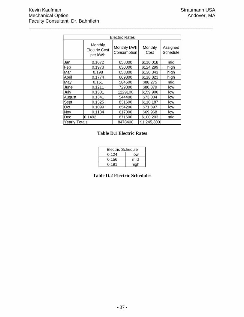
Kevin Kaufman Straumann USA Mechanical Option Andover, MA Faculty Consultant: Dr. Bahnfleth _____________________________________________________________________
- 37 -
Monthly Electric Cost
per kWh
Monthly kWh Consumption
Monthly Cost
Assigned Schedule
Jan 0.1672 658000 $110,018 midFeb 0.1973 630000 $124,299 highMar 0.198 658300 $130,343 highApril 0.1774 669800 $118,823 highMay 0.151 584600 $88,275 midJune 0.1211 729800 $88,379 lowJuly 0.1301 1229100 $159,906 lowAugust 0.1341 544400 $73,004 lowSept 0.1325 831600 $110,187 lowOct 0.1099 654200 $71,897 lowNov 0.1134 617000 $69,968 lowDec 0.1492 671600 $100,203 mid
8478400 $1,245,300
Electric Rates
Yearly Totals
Table D.1 Electric Rates
0.124 low0.156 mid0.191 high
Electric Schedule
Table D.2 Electric Schedules

Kevin Kaufman Straumann USA Mechanical Option Andover, MA Faculty Consultant: Dr. Bahnfleth _____________________________________________________________________
- 38 -
Cost per Therm
Monthly Therm Consumption Monthly Cost Assigned
Schedule
Jan 1.6803 19671 $33,053 highFeb 1.5686 16125 $25,294 midMar 1.5267 16574 $25,304 midApril 1.5703 6154 $9,664 midMay 1.3863 4181 $5,796 lowJune 1.523 1436 $2,187 midJuly 1.5172 681 $1,033 midAugust 1.6792 1302 $2,186 highSept 1.6127 1107 $1,785 midOct 1.4964 3731 $5,583 midNov 1.6266 10630 $17,291 midDec 1.7743 22766 $40,394 high
104358 $169,569Yearly Totals
Gas Rates
Table D.3 Fuel Rates
low 1.386mid 1.555high 1.711
Fuel Schedule
Table D.4 Fuel Schedules
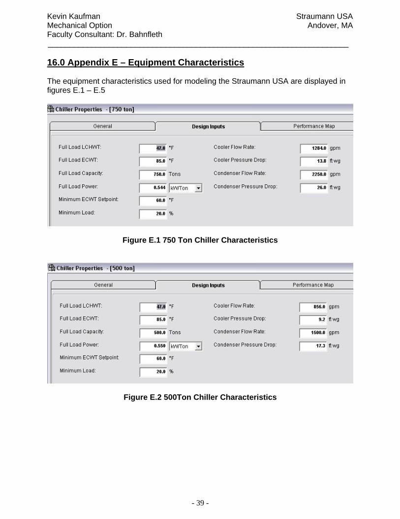
Kevin Kaufman Straumann USA Mechanical Option Andover, MA Faculty Consultant: Dr. Bahnfleth _____________________________________________________________________
- 39 -
16.0 Appendix E – Equipment Characteristics The equipment characteristics used for modeling the Straumann USA are displayed in figures E.1 – E.5
Figure E.1 750 Ton Chiller Characteristics
Figure E.2 500Ton Chiller Characteristics

Kevin Kaufman Straumann USA Mechanical Option Andover, MA Faculty Consultant: Dr. Bahnfleth _____________________________________________________________________
- 40 -
Figure E.3 350 Ton Chiller Characteristics
Figure E.4 Fuel Oil Boiler Characteristics

Kevin Kaufman Straumann USA Mechanical Option Andover, MA Faculty Consultant: Dr. Bahnfleth _____________________________________________________________________
- 41 -
Figure E.5 Cooling Tower Characteristics
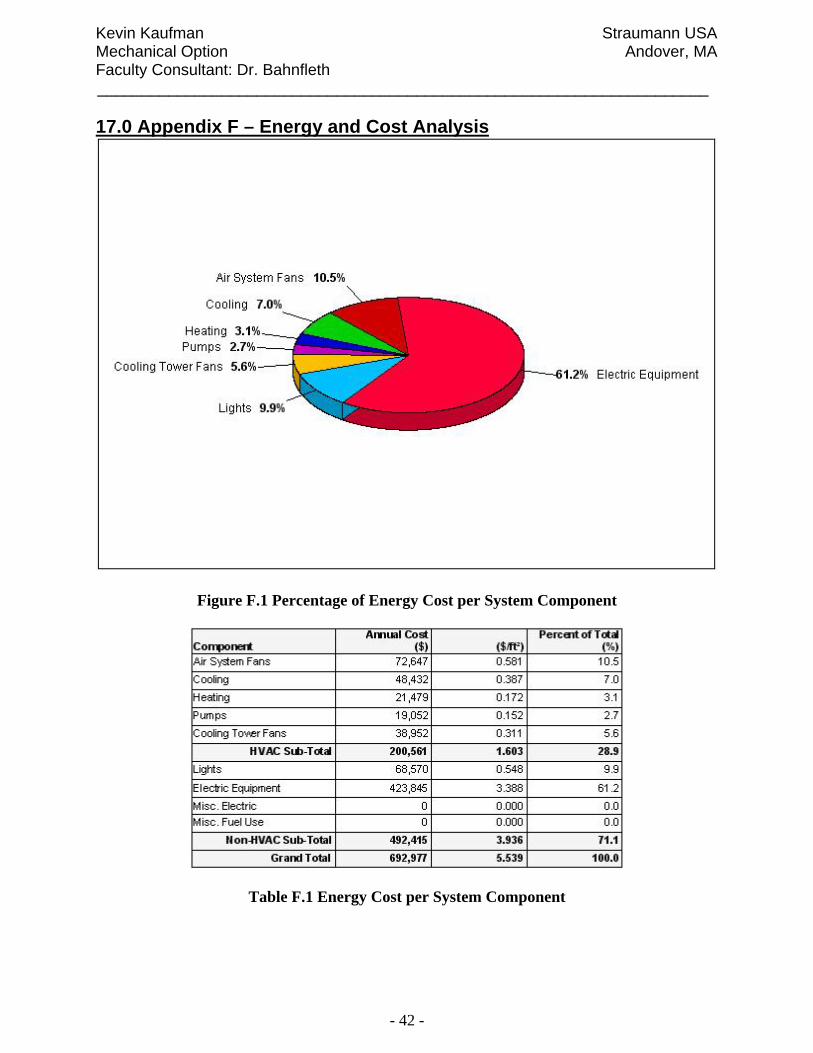
Kevin Kaufman Straumann USA Mechanical Option Andover, MA Faculty Consultant: Dr. Bahnfleth _____________________________________________________________________
- 42 -
17.0 Appendix F – Energy and Cost Analysis
Figure F.1 Percentage of Energy Cost per System Component
Table F.1 Energy Cost per System Component

Kevin Kaufman Straumann USA Mechanical Option Andover, MA Faculty Consultant: Dr. Bahnfleth _____________________________________________________________________
- 43 -
Figure F.2 Percentage of Annual Energy Cost
Table F.2 Annual HVAC/Non-HVAC Energy Costs
Table F.3 Annual Costs per Fuel Type