metric fed-std-791d november 6, 2007 superseding fed...
TRANSCRIPT
METRIC FED-STD-791D November 6, 2007 SUPERSEDING FED-STD-791C September 30, 1986
FEDERAL STANDARD
TESTING METHOD OF LUBRICANTS, LIQUID FUELS, AND RELATED PRODUCTS AMSC N/A FSC 91GP DISTRIBUTION STATEMENT A. Approved for public release, distribution is unlimited.
Downloaded from http://www.everyspec.com
FED-STD-791D
August 24, 2006
Foreword This Federal Test Method Standard is issued in loose leaf form to permit the insertion or removal of new or revised sections and test methods. All users of Federal Test Method Standards should keep them up to date by inserting revised or new sections and test methods as issued and removing superseded and cancelled pages. New and revised material and cancellations will be issued under Change Notices which will be numbered consecutively and will bear the date of issuance. Change Notices should be retained and filed in front of the Alphabetical Index of the Standard until such time as they are superseded by a reissue of the entire standard. This federal standard is approved by the Commissioner, Federal Supply Services, General Service Administration for use of all Federal agencies.
1
Downloaded from http://www.everyspec.com

FED-STD-791D
CONTENTS Title Method Introduction - Indexes and Addresses Color of Gasoline 103.6 Cloud Intensity at Low Temperature 202.1 Pour Stability of Lubricating Oils 203.1 Penetration of Lubricating Greases After Prolonged Working 313.3 Gear Wear 335.3 Evaporation Loss of Lubricating Greases and Oils 350.2 (High Temperature) Effect of Evaporation on Flammability 352.1 Evaporation 353.1 Stroking Properties of Hydraulic Brake Fluids 361.4 Emulsification Tendencies of Petroleum Fuels by Multiple 550.1 Contact Extractions Quenching Speed 1110.2 Explosive Vapors in Boiler Fuel Oil 1151.2 Thermal Stability of Lubricating and Hydraulic Fluid 2508.1 Dirt Content of Grease 3005.4 Water Displacement and Water Stability 3007.2 Solid Particle Contamination in Hydraulic Fluids 3009.3 Solid Particle Contamination in Aircraft Turbine Engine 3010.1 Lubricants (Gravimetric Procedure) Determination of Particulate Matter in Aerospace Hydraulic Fluids 3012 Determination of Particulate Contamination in Synthetic 3013 Turbine Engine Lubricants Fatty Oil in Cutting Fluids by Infrared Spectrophotometry 3110.1 Sulfur in Cutting Fluids (Active and Total) 3180.2 Emulsion (Petroleum and Petroleum-Like Products) 3201.7 Emulsion (Soluble Cutting Oils) 3205.3 Compatibility of Turbine Lubricating Oils 3403.2 High Temperature Deposits and Oils Degradation Characteristics 3410.1 Of Aviation Turbine Oils Thermal Stability and Corrosivity of Aircraft Turbine Engine 3411.1 Lubricants Compatibility Characteristics of Universal Gear Lubricants 3430.2 Compatibility of Elastomers with Aircraft Turbine Lubricants 3432.1 Compatibility of Synthetic Aircraft Turbine Lubricants with 3433 Silicone Rubber Storage Volubility Characteristics of Universal Gear Lubricants 3440.1 Bearing Deposition of Aviation Turbine Engine Lubricants 3450 Bearing Compatibility of Turbine Oils 3452.2 Channeling Characteristics of Lubricants 3456.2 Hydrolytic Stability 3457.2 Low Temperature Stability Test for Oil 3458.1
2
Downloaded from http://www.everyspec.com

FED-STD-791D
Low Temperature Stability 3459.1 Stability of Grease in Hot Water (Water Immersion) 3463.2 Storage Stability Test or Fluids and Lubricants 3465.1 Storage Stability of Lubricating Grease 3467.1 Homogenity and Miscibility of Oils 3470.1 Volatility of Blended Oils 3480.1 Monobasic Acid Components of Synthetic Ester Lubricants 3500.1 by Gas Chromatography Swelling of Synthetic Rubbers 3603.5 Swelling of Synthetic Rubber by Aircraft Turbine Lubricants 3604.2 Molybdenum Disulfide Purity 3710.1 Molybdenum Disulfide Content of Lubricating Grease 3720.2 Molybdenum Disulfide Content of Non-Soap Thickened 3722.2 Lubricating Greases Film Thickness of Dry Solid Film Lubricants 3816.1 Corrosion Protection by Coating: Salt-Spray (Fog) Test 4001.3 Deposit-Foaming Tendencies of Aircraft Turbine Lubricants 5003.2 Corrosiveness of Greases or Semi-Solid Products at 25°C 5304.5 Corrosiveness of Lubricants at 232° C (450° F ) 5305.1 Corrosiveness of Emulsifyable Cutting Fluids 5306.5 Corrosiveness and Oxidation Stability of Light Oils 5308.7 Corrosiveness of Greases (copper strip, 100 °C) 5309.5 Corrosion of Lead by Lubricating Oils 5321.2 Corrosion Protection (Humidity Cabinet) 5329.2 Corrosion Protection of Steel Against Sulfurous Acid-Salt 5331.1 Spray by Solid Film Lubricants Resistance of Grease to Fuel 5414.4 Resistance of Grease to Water and a 1:1 Water-Ethanol Solution 5415.1 Nitrite-Type Ignition Improvers in Diesel Fuel 6050.1 High-Temperature--High Pressure Spray Ignition 6052.1 Manifold Ignition Test 6053.1 Load Carrying Capacity of Lubricating Oils (Ryder Gear Machine) 6508.2 High Temperature Gear Load –Carrying Capacity of Lubricating Oils 6517 Low Temperature Torque Test Method for Lubricating Greases 7501 Solvent Cleaning Power by a Soil Test Method 7502 Materiel Handling Safety Precaution 10000 List of materials cited in each test method Appendix A Cross reference list between index number (i.e., material name) And test method number where the material is cited Appendix B
3
Downloaded from http://www.everyspec.com

FED-STD-791D
Introduction
TESTING METHOD OF LUBRICANTS, LIQUID FUELS, AND RELATED PRODUCTS
1. SCOPE
1.1 This test method standard is composed of standard test methods for sampling, inspecting and testing lubricants, liquid fuels and related products. It is issued pursuant to the Federal Property and Administration Services Act of 1949, as amended and its application to the purchase of commodities referred to herein is mandatory on all Federal agencies.
1.2 The test methods of this standard, when cited in a specification form an integral part
of that specification. Such a citation ,although referenced to the basic number of a method is intended to apply to the latest version of the method as revised (see paragraph 2)and as amended by any subsequent Change Notices to this standard
CAUTION
Change Notices are not cumulative. Therefore all notices must be consulted to insure that the latest requirements are observed
1.3 Some methods are identical to those published by the ASTM International. These
methods are listed in the indexes together with their corresponding ASTM method numbers and the details of such test methods are omitted from this standard.
2. NUMBERING SYSTEM
2.1 The test methods are identified by numerical designations, each consisting of a basic number and in some instances a revision number (decimal)
a. Basic number. The basic number of a method is its official designation and should be used without revision number whenever the method is referenced. The number always refers to the same method of determination and the same accuracy, and the same end results regardless of revision status.
b. Revision Number. Revision numbers appear as decimal addition to the basic numbers. These are assigned to basic numbers when changes are made in the method to clarify it or to give additional details that will increase the reproducibility of the test results.
4
Downloaded from http://www.everyspec.com

FED-STD-791D
3. NOTES
3.1 Purchase of specification and Standards. Federal and military specifications and standards may be obtained under general provisions in the index of specifications and standards. They can be found in the websites also. Federal Government activities may obtain the index from established distribution points within their agencies. All others may purchase the index with cumulative monthly supplements as issued from the Superintendent of documents U.S. Government Printing office, Washington D.C 20402
3.2 Purchase of ASTM test methods. ASTM test methods may be purchased from the
ASTM international, 100 Barr Harbor Drive, West Conshohocken, PA 19428 3.3 Patent notice. When Government drawings, specifications or other data are used for
any purpose other than in connection with a definitely related government operation, the United States Government thereby incurs no responsibility nor any obligation whatsoever; and the fact that the government may have furnished, formulated or in any way supplied the said drawings, specifications or other data, is not to be regarded by implication or otherwise as in any manner licensing the holder or any other person or corporation or conveying any rights or permission to manufacturer, use or sell any patented invention that may in any way be related thereto.
5
Downloaded from http://www.everyspec.com

FED-STD-791D
Table I. Numerical index of test method Method No
Method Title Replacement test
Test cancelled by
103.6 Color of gasoline 202.1 Cloud intensity at low temperature 203.1 Pour stability at low temperature 204.1 Diluted pour point None Navy 313.3 Penetration of lubricating greases after
prolonged working
321.3 Oil separation from lubricating greases (static technique)
ASTM D 6184
Navy
335.3 Gear wear 339.6 Performance of diesel engine lubricating oils
under severe None Navy
347.3 Performance of diesel engine lubricating oils under severe operating condition
None Navy
350.2 Evaporation loss of lubricating greases and oils (high Temperature)
352.1 Effect of evaporation on flammability 353.1 Evaporation 354.1 Performance of lubricating oils in a two cycle
diesel engine under cyclic,turbo-supercharged conditions
None Army
355 Performance of lubricating oils in a two cycle diesel engine under cyclic,turbo-supercharged conditions
ASTM D 5862
Army
361.4 Stroking properties of hydraulic brake fluids 500.1 Induction system deposit ( ISD ) tendencies of
motor gasoline ASTM D 6241
Army
550.1 Emulsification tendencies of petroleum fuels by multiple contact extractions
1110.2 Quenching speed 1151.2 Explosive vapors in boiler fuel oil 1303.2 Flock point (refrigerant compressor oil) None Navy 2508.1 Thermal stability of lubricating and hydraulic
fluids
3005.4 Dirt content of grease 3006.3 Contamination in engine oil None Navy 3007.2 Water displacement and water stability 3009.3 Solid particle contamination in hydraulic fluids 3010.1 Solid particle contamination in aircraft turbine
engine Lubricants (gravimetric procedure)
3011.1
Particulate contamination in aerospace hydraulic fluid using particle counter
None AF
6
Downloaded from http://www.everyspec.com
FED-STD-791D
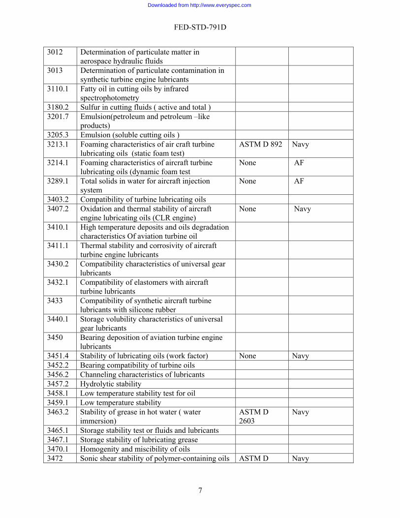
3012
Determination of particulate matter in aerospace hydraulic fluids
3013 Determination of particulate contamination in synthetic turbine engine lubricants
3110.1 Fatty oil in cutting oils by infrared spectrophotometry
3180.2 Sulfur in cutting fluids ( active and total ) 3201.7 Emulsion(petroleum and petroleum –like
products)
3205.3 Emulsion (soluble cutting oils ) 3213.1 Foaming characteristics of air craft turbine
lubricating oils (static foam test) ASTM D 892 Navy
3214.1 Foaming characteristics of aircraft turbine lubricating oils (dynamic foam test
None AF
3289.1 Total solids in water for aircraft injection system
None AF
3403.2 Compatibility of turbine lubricating oils 3407.2 Oxidation and thermal stability of aircraft
engine lubricating oils (CLR engine) None Navy
3410.1 High temperature deposits and oils degradation characteristics Of aviation turbine oil
3411.1 Thermal stability and corrosivity of aircraft turbine engine lubricants
3430.2 Compatibility characteristics of universal gear lubricants
3432.1 Compatibility of elastomers with aircraft turbine lubricants
3433 Compatibility of synthetic aircraft turbine lubricants with silicone rubber
3440.1 Storage volubility characteristics of universal gear lubricants
3450 Bearing deposition of aviation turbine engine lubricants
3451.4 Stability of lubricating oils (work factor) None Navy 3452.2 Bearing compatibility of turbine oils 3456.2 Channeling characteristics of lubricants 3457.2 Hydrolytic stability 3458.1 Low temperature stability test for oil 3459.1 Low temperature stability 3463.2 Stability of grease in hot water ( water
immersion) ASTM D 2603
Navy
3465.1 Storage stability test or fluids and lubricants 3467.1 Storage stability of lubricating grease 3470.1 Homogenity and miscibility of oils 3472 Sonic shear stability of polymer-containing oils ASTM D Navy
7
Downloaded from http://www.everyspec.com

FED-STD-791D
2603 3480.1 Volatility of blended oils 3500.1 Monobasic acid components of synthetic ester
lubricants by gas chromatography
3603.5 Swelling of synthetic rubbers ASTM D 4289
Army
3604.2 Swelling of synthetic rubber by aircraft turbine lubricants
3710.1 Molybdenum disulfide purity 3720.2 Molybdenum disulfide content of lubricating
grease
3722.2 Molybdenum disulfide content of non-soap thickened lubricating greases
3816.1 Film thickness of dry solid film lubricants 4001.3 Corrosion protection by coating: salt-spray
(fog) test
5003.2 Deposit- foaming tendencies of aircraft turbine lubricants
5101.7 Neutrality (qualitative) ASTM D 1093
Navy
5102.1 Acid and base number by extraction (color-indicator titration)
None Navy
5304.5 Corrosiveness of greases or semi-solid products at 25°C
5305.1 Corrosiveness of lubricants at 232° C (450° F ) 5306.5 Corrosiveness of emulsifyable cutting fluids 5307.2 Corrosiveness and oxidation stability of aircraft
turbine ASTM D 4636
AF
5308.7 Corrosiveness and Oxidation Stability of Light Oils
ASTM D 4636
Army
5309.5 Corrosiveness of grease (copper strip, 100 °C) 5321.2 Corrosion of lead by lubricating oils 5322.2 Corrosiveness of oil on bimetallic couple ASTM D
6547 ARMY
5327 Fuel system icing inhibitors in hydrocarbon fuels (iodometric method)
None AF
5329.2 Corrosion protection (humidity cabinet) 5330 Fuel system icing inhibitor in hydrocarbon fuel
(calorimetric method) None AF
5331.1 Corrosion protection of steel against sulfurous acid-salt spray by solid film lubricants
5333.1 Fuel system icing inhibitor by freezing point depressing method
None AF
5340.2 Fuel system icing inhibitor in hydrocarbon fuels (refractometer method)
ASTM D 5006
AF
8
Downloaded from http://www.everyspec.com

FED-STD-791D
5341 Fuel system icing inhibitor in hydrocarbon fuels (redox method)
None AF
5342 Fuel system icing inhibitor in hydrocarbon fuels (hand refractometer method)
ASTM D 5006
Navy
5350.1 Silting index of hydrocarbon fuels None Navy 5414.4 Resistance of grease to fuel 5415.1 Resistance of grease to water and a 1:1 water
ethanol solution
6050.1 Nitrate- type ignition improvers in diesel fuel 6052.1 High temperature , High pressure spray ignition 6053.1 Manifold ignition test 6505.2 Load carrying capacity of universal gear
lubricants by the Timken machine ASTM D 2782
Navy
6508.2 Load carrying capacity of lubricating oils (Ryder gear machine)
6509.2 Gear-fatigue characteristics of aircraft gas turbine lubricants at 204°C
None Navy
6511.2 Load carrying capacity of lubricating oils at 204° C
None Navy
6516.2 Oscillation test of grease in helicopter bearings None Navy 6517 High temperature gear load –carrying capacity
of lubricating oils
6520.1 Extreme pressure properties of lubricants (four ball testers)
ASTM D 2783
Navy
7501 Low Temperature Torque Test Method for Lubricating Greases
7502 Solvent Cleaning power by a Soil Test Method 10000 Material Handling Safety Precaution
Table II - Alphabetical key word index of test methods Method Title Method
No Replacement
test Test
Cancelled by
Acid and base number by extraction (color indicator titration)
5102.1 None NAVY
Bearing deposition of aviation turbine engine lubricants
3450
Bearing compatibility of turbine oils 3452.2 Channeling characteristics of lubricants 3456.2 Cloud intensity at low temperature 202.1 Color of gasoline 103.6 Compatibility characteristics of universal gear lubricants
3430.2
Compatibility of elastomers with air craft turbine lubricants
3432.1
9
Downloaded from http://www.everyspec.com
FED-STD-791D
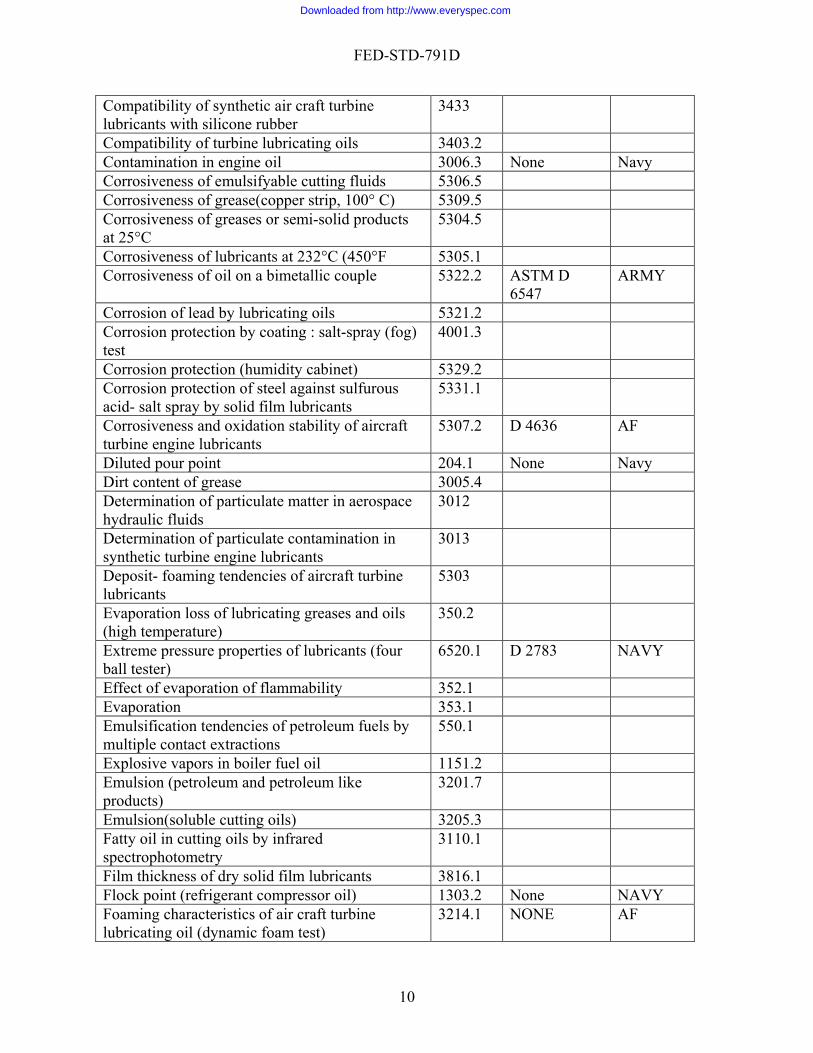
Compatibility of synthetic air craft turbine lubricants with silicone rubber
3433
Compatibility of turbine lubricating oils 3403.2 Contamination in engine oil 3006.3 None Navy Corrosiveness of emulsifyable cutting fluids 5306.5 Corrosiveness of grease(copper strip, 100° C) 5309.5 Corrosiveness of greases or semi-solid products at 25°C
5304.5
Corrosiveness of lubricants at 232°C (450°F 5305.1 Corrosiveness of oil on a bimetallic couple 5322.2 ASTM D
6547 ARMY
Corrosion of lead by lubricating oils 5321.2 Corrosion protection by coating : salt-spray (fog) test
4001.3
Corrosion protection (humidity cabinet) 5329.2 Corrosion protection of steel against sulfurous acid- salt spray by solid film lubricants
5331.1
Corrosiveness and oxidation stability of aircraft turbine engine lubricants
5307.2 D 4636 AF
Diluted pour point 204.1 None Navy Dirt content of grease 3005.4 Determination of particulate matter in aerospace hydraulic fluids
3012
Determination of particulate contamination in synthetic turbine engine lubricants
3013
Deposit- foaming tendencies of aircraft turbine lubricants
5303
Evaporation loss of lubricating greases and oils (high temperature)
350.2
Extreme pressure properties of lubricants (four ball tester)
6520.1 D 2783 NAVY
Effect of evaporation of flammability 352.1 Evaporation 353.1 Emulsification tendencies of petroleum fuels by multiple contact extractions
550.1
Explosive vapors in boiler fuel oil 1151.2 Emulsion (petroleum and petroleum like products)
3201.7
Emulsion(soluble cutting oils) 3205.3 Fatty oil in cutting oils by infrared spectrophotometry
3110.1
Film thickness of dry solid film lubricants 3816.1 Flock point (refrigerant compressor oil) 1303.2 None NAVY Foaming characteristics of air craft turbine lubricating oil (dynamic foam test)
3214.1 NONE AF
10
Downloaded from http://www.everyspec.com

FED-STD-791D
Foaming characteristics of air craft turbine lubricating oils (static foam test)
3213.1
Fuel system icing inhibitor in hydrocarbon fuels (calorimetric method)
5330 ASTM D 5006
AF
Fuel system icing inhibitors by freezing point depression method
5333.1 NONE AF
Fuel system icing inhibitor in hydrocarbon fuel (iodometric method)
5327 None AF
Fuel system icing inhibitor in hydrocarbon fuel (redox method)
5341 NONE AF
Fuel system icing inhibitor in hydrocarbon fuel (refractometer method)
5340.2 ASTM D 5006
AF
Fuel system icing inhibitor in hydrocarbon fuel (hand refractometer method)
5342 ASTM D 5006
NAVY
Gear-fatigue characteristics of aircraft gas turbine lubricants at 204°C
6509.2 None NAVY
High temperature , High pressure spray ignition 6052.1 High temperature deposits and oil degradation characteristics of aviation turbine oils
3410.1
High temperature gear load –carrying capacity of lubricating oils
6517
Homogeneity and miscibility of oils 3470.1 Hydrolytic stability 3457.2 Induction system deposit ( ISD ) tendencies of motor gasoline
500.1 ASTM D 6241
ARMY
Low temperature stability test for oil 3458.1 Low temperature stability 3459.1 Low Temperature Torque Test Method For Lubricating Greases
7501
Load carrying capacity of lubricating oils (Ryder gear machine)
6508.2
Load carrying capacity of lubricating oils at 204° C
6511.2 None NAVY
Load carrying capacity of universal gear lubricants by the Timken machine
6505.2 ASTM D 2782
NAVY
Molybdenum disulfide purity 3710.1 Molybdenum disulfide content of lubricating grease
3720.2
Molybdenum disulfide content of non-soap thickened lubricating greases
3722.2
Monobasic acid components of synthetic ester lubricants
3500.1
Manifold ignition test 6053.1 Materiel handling safety precaution 10000 Nitrite type ignition improvers in diesel fuel 6050.1
11
Downloaded from http://www.everyspec.com

FED-STD-791D
Neutrality (qualitative) 5101.7 D 1093 NAVY Oil separation from lubricating greases (static technique)
321.3 D 6184 NAVY
Oxidation and thermal stability of aircraft engine lubricating oils (CLR engine)
3289.1 None AF
Oscillation test of grease in helicopter bearings 6516.2 None NAVY Oxidation and thermal stability of aircraft engine lubricating oils( CLR engine)
3407.2 None NAVY
Particulate contamination in aerospace hydraulic fluid
3011.1 None AF
Penetration of lubricating greases after prolonged working
313.3
Performance of arctic lubricating oils in a two cycle diesel engine under cyclic, turbo supercharged conditions
354.1 None ARMY
Performance of aviation piston engine oils in CLR engine (low temperature dispersancy and detergency)
347.3 None NAVY
Performance of diesel engine lubricating oils under severe operating conditions
339.6 None NAVY
Performance of lubricating oils in a two cycle diesel engine under cyclic turbo supercharged conditions
355 ASTM D 5862
ARMY
Pour stability at low temperature 203.1 Quenching speed 1110.2 Resistance of grease to fuel 5414.4 Resistance of grease to water and a 1:1 water-ethanol solution
5415.1
Silting index of hydrocarbon fuels 5350.1 None NAVY Solid particle contamination in hydraulic fluids 3009.3 Solid particle contamination in aircraft turbine engine lubricants (gravimetric procedure)
3010.1
Solvent cleaning power by a soil test method 7502 Sonic shear stability of polymer-containing oils 3472 Stability of lubricating oils (work factor) 3451.4 None NAVY Storage volubility characteristics of universal gear lubricants
3440.1
Storage stability test or fluids and lubricants 3465.1 Storage stability of lubricating grease 3467.1 Stroking properties of hydraulic brake fluids 361.4 Thermal Stability of Lubricating and hydraulic Fluid
2508.1
Thermal stability and corrosivity of aircraft turbine engine lubricants
3411.1
Total solids in water for aircraft injection system 3289.1 None AF
12
Downloaded from http://www.everyspec.com

FED-STD-791D
Volatility of blended oils 3480.1 Water displacement and water stability 3007.2 Sulfur in cutting fluids ( active and total ) 3180.2 Swelling of synthetic rubber by aircraft turbine lubricants
3604.2
Table III. Numerical Index of Cancelled and Superseded test Method Title of cancelled Test Method Cancelled method
Number Substitute Method
Diluted Pour Point 204.1 None Oil Separation from Lubricating Greaser (Static Technique)
321.3 ASTM D 6184
Performance of Diesel Engine Lubricating Oil Under severe operating condition
339.6 None
Performance of Aviation Piston Engine Oil In CLR Engine(low temperature dispersancy and detergency)
347.3 None
Performance of Arctic Lubricating Oil in a two cycle diesel Engine under cyclic, turbo supercharge condition
354.1 None
Performance of Engine Lubricating Oils in a Two Cycle Diesel Engine under cyclic Turbo supercharge condition
355 ASTM D 5862
Induction System Deposit (ISD) Tendencies of Motor Gasoline
500.1 ASTM D 6241
Flock Point ( refrigerant compressor oil) 1303.2 None Contamination of Engine oil 3006.3 None Particulate Contamination in Aerospace Hydraulic Fluids Using the HIAC Particulate Counter
3011 None
Foaming Characteristics of air craft turbine lubricating oils(Static foam test)
3213.1 ASTM D 892
Foaming characteristics of air craft turbine lubricating oils(dynamic foam test)
3214.1 NONE
Total solids in water for aircraft injection system 3289.1 NONE Oxidation and Thermal stability of air craft turbine engine lubricating oils(CLR Engine)
3407.2 NONE
Stability of Grease in Hot Water (Water Immersion)
3463.2 ASTM D 2603
Stability of lubricating oils (work factor) 3451.4 None Sonic shear stability of polymer-containing oil 3472 ASTM
D 2603 Swelling of Synthetic Rubbers 3603.5 ASTM D 4289 Neutrality ( Qualitative) 5101.7 ASTM
D 1093
13
Downloaded from http://www.everyspec.com
FED-STD-791D
Acid and base number by extraction (color indicator)
5102.1 None
Corrosiveness and oxidation stability of aircraft turbine lubricants
5307.2 ASTM D 4636
Corrosiveness and Oxidation Stability of Light Oils
5308.7 ASTM D 4636
Corrosiveness of Oil on a Bimetallic Couple 5322.2 ASTM D 6547 Fuel system icing inhibitor in hydrocarbon fuels (iodometric method)
5327 None
Fuel system icing inhibitor in hydrocarbon fuels (calorimetric method
5330 None
Fuel system icing inhibitor by freezing point depression method
5333.1 None
Fuel system icing inhibitor in hydrocarbon fuels (Refractometer method)
5340.2 ASTM D 5006
Fuel system icing inhibitor in hydrocarbon fuels(Redox method)
5341 None
Fuel system icing inhibitor in hydrocarbon fuels ( hand refractometer method)
5342 ASTM D 5006
Silting index of hydrocarbon fuels 5350.1 None Load carrying capacity of universal gear lubricants by the Timken machine
6505.2 ASTM D 2782
Gear fatigue characteristics of air craft gas turbine
6509.2 None
Load carrying capacity of lubricating oils at 204º 6511.2 None Oscillating test of grease in Helicopter bearings 6516.2 None Extreme pressure properties of lubricants (four ball tester)
6520.1 ASTM D 2783
Table IV. Numerical index of ASTM Equivalents for Federal standard test methods. ASTM test method FED-STD-791 Test Method D892 3213.1 D1093 5101.7 D2603 3472 D2782 6505.2 D2783 6520.1 D4636 5307.2 and 5308.7 D5006 5342 D5862 355.3 D6184 321.3
14
Downloaded from http://www.everyspec.com

FED-STD-791D
Table V. Identifying symbols and addresses of activities responsible for preparation and maintenance of test methods.
Symbol Service Activity NAPC Navy Department of the Navy
Naval Air Systems Command Fuels and Lubricants Team Air-4.4.122229 Elmer Road, Bldg 2360 Patuxent River, MD 20670-1534
AFTL Air Force Department of the Air Force HQ Air Force Petroleum Agency Wright-Peterson AFB, OH 45433-7632
AR Army Department of the Army US Army Armament Research and Development Center Dover, New Jersey 07801-5001
SH Navy Department of the Navy Navel Sea Systems Command Washington D.C. 20362
AFWAL/POSF Air Force Department of the Air Force Air Force Wright Aeronautical Laboratories POSF
AFWAL/POSL Air Force USAF/ Aero Propulsion Laboratory AFWAL/POSL Wright- Patterson AFB, OH 45433-6563
AT Army US Army TARDEC/RDECOM Fuel and Lubricants Technology Team Warren, Michigan 48092
15
Downloaded from http://www.everyspec.com
FED-STD-791D
Method 103.6 September 30, 1986
COLOR OF GASOLINE 1. SCOPE
1.1 This method is used for determining the acceptability of color of dyed gasolines (aviation or motor). 2. SUMMARY
2.1 The method consists of comparing the hue and color intensity of the gasoline with those of permanent-color (glass) standards. 3. SAMPLE SIZE
3.1 Approximately 480 mL of gasoline to be tested. 4. REFERENCES, STANDARDS, AND APPARATUS
4.1 Color comparator (Hellige Inc., Garden City, N.Y., Aqua-Testers No. 611A, or equal), split-field, for viewing simultaneously (by transmitted light) the sample and the combination of the reference liquid and the permanent-color standard.
4.2 Fluid tubes (2), glass, 20.0-cm viewing depth, with a fused-on plane bottom plate (Hellige Nessler tube No. 611-T, or equal).
4.3 Plungers, fluid-tube (2), polished optical glass (Hellige Nessler plunger No. 611-PL, or equal).
4.4 Gasoline color standards, permanent-color glass disc (as required):
a. Aviation gasoline standard (Hellige 611-95 and 611-96, or equal). b. Motor gasoline standard (Hellige 611-97 or equal).
5. MATERIALS
5.1 CAUTION - SOME MATERIALS ARE TOXIC AND HAZARDOUS. The chemical materials listed in this section must be handled carefully. Federal Test Method 10000, Material Handling Safety Precautions, is a reference which lists all toxic and hazardous materials cited in FTMS 791. The synonyms, life hazard, flammability, handling and storage precautions, emergency treatment and measures, and spill practices of each chemical are explained.
5.2 Reference liquid; either a sample of the gasoline under test (prior to addition of dye or tetraethyl lead), or distilled [1,3,0].
16
Downloaded from http://www.everyspec.com

FED-STD-791D
6. PROCEDURE
6.1 Clean the optical surfaces of the color comparator.
6.2 Insert empty tubes in the color comparator, and adjust the position of the light source until the intensities of the light from both halves of the comparator split-field are equal.
6.3 Rinse and fill one of the tubes with reference liquid, and insert the plunger.
6.4 Wipe all excess reference liquid from the outside of the tube and from the top of the plunger, and insert the tube in the one side of the comparator.
6.5 Rinse and fill the remaining tube with the sample and insert the plunger.
6.6 Wipe all excess sample from the outside of the tube and from the top of the plunger, and insert the tube in the other side of the comparator.
6.7 Insert the color standard(s) into the comparator, and rotate the standard until the color selection can be viewed by transmitted light.
6.8 Turn on the light source, and visually compare the two fields for hue and intensity. (When testing aviation gasoline, compare its hue and intensity with the minimum and maximum color sections of the glass color standards.) 7. CALCULATIONS
7.1 This section is not applicable to the test procedure. 8. REPORTING
8.1 Report the color as acceptable if the hue is approximately the same as the standard and if the intensity of the color is as follows:
a. Aviation gasoline intensity: between minimum and maximum standards. b. Motor gasoline intensity: equal to or greater than standards.
9. PRECISION
9.1 Precision data have not been developed for this method.
Method Prepared By:
Army - ME - 1986 September 30, 1986
17
Downloaded from http://www.everyspec.com
FED-STD-791D
Method 202.1 September 30, 1986
CLOUD INTENSITY AT LOW TEMPERATURE 1. SCOPE.
1.1 This method is used for determining the stability (at low temperature) of hydraulic fluids or highly refined light lubricating oils. 2. SUMMARY
2.1 The method consists of storing a sample at -54°C (-65°F) or lower for a period required by the petroleum product specification, agitating it, and comparing its turbidity with a standard. The sample is poured in a sealed, cleaned, dried sample bottle and stored for a specified number of hours at a maximum of -54°C (-65°F). Within 5 min of the comparison time, the turbidity standard is shaken vigorously for 10 s and poured into a sample bottle. At the end of the storage time, the sample is removed from cold storage and shaken vigorously for 10 s. The frost is eliminated from the sample bottle and it is compared with the turbidity standard. The turbidity of the sample relative to the standard is reported as less than, more than, or equal to the standard. 3. SAMPLE SIZE.
3.1 Approximately 120 mL of test oil (or fluid). 4. REFERENCES, STANDARDS, AND APPARATUS.
4.1 Cooling apparatus, -54°C (-65°F) or lower (ASTM cloud and pour point apparatus, or equal).
4.2 Sample bottles (2), clear-glass 120 mL, with cork stoppers. 5. MATERIALS.
5.1 CAUTION - SOME MATERIALS ARE TOXIC AND HAZARDOUS. The chemical materials listed in this section must be handled carefully. Federal Test Method 10000, Material Handling Safety Precautions, is a reference which lists all toxic and hazardous materials cited in FTMS 791. The synonyms, life hazard, flammability, handling and storage precautions, emergency treatment and measures, and spill practices of each chemical are explained.
5.2 Methanol-glycerol (technical grade), 1:1 solution (by volume) [1,3,0].
5.3 Turbidity standard, prepared within 30 min of use, as follows:
18
Downloaded from http://www.everyspec.com

FED-STD-791D
a. Pour 25 mL of 0.00322 M barium chloride into a 250-mL volumetric flask [0,0,2]. b. Add 125 mL of 0.0050 N sulfuric acid, and shake well to insure complete
precipitation [3,0,2]. c. Add approximately 25 mL of l N sodium hydroxide to make solution alkaline
[3,0,1]. d. Add distilled water to bring total volume to 250 mL. e. Pour solution into a sample bottle, and seal it tightly with stopper.
NOTE: For red hydraulic liquids, in place of plain distilled water, use distilled water
containing 200 ppm red dye (National Erie Bordeaux B, manufactured by National Aniline Division of Allied Chemical and Dye Corp., or equivalent). 6. PROCEDURE.
6.1 Clean sample bottles, and dry at approximately 100°C for a minimum of 24 h.
6.2 Pour sample into bottle, and seal bottle tightly with stopper.
6.3 Store sample for the specified number of hours at a temperature no warmer than -54°C (-65°F).
6.4 Before end of storage period, cool the methanol-glycerol solution to -54°C (-65°F).
6.5 Within 5 min of making comparison, shake the turbidity standard vigorously for 10 s, and pour into the other sample bottle.
6.6 At the end of the storage period, remove sample from cold storage, and shake vigorously for approximately 10 s.
6.7 Dip sample into methanol-glycerol solution to eliminate frosting (if necessary), and within one minute of removal from cold storage, compare sample visually with the turbidity standard.
6.8 Note the turbidity of the sample. 7. CALCULATIONS
7.1 This section is not applicable to the test procedure. 8. REPORTING.
8.1 Report turbidity of sample relative to standard as less than, more than, or equal to the standard.
19
Downloaded from http://www.everyspec.com
FED-STD-791D
9. PRECISION.
9.1 Precision data have not been developed for this method.
Method Prepared by:
Army - ME - 1986
20
Downloaded from http://www.everyspec.com

FED-STD-791D
Method 203.1 September 30, 1986 POUR STABILITY OF LUBRICATING OILS
1. SCOPE
1.1 The test for pour stability is primarily intended for use with engine lubrication oils. However, by establishing proper final cooling temperatures, this method can be used for other lubricating oils such as power transmission fluids and hydraulic oils.
1.2 Good correlation with field test results has been obtained. However, since only two temperature/time cycles are reproduced, this method cannot duplicate all field ambient cycle conditions. 2. SUMMARY
2.1 After preliminary warming, the sample is subjected to a controlled temperature/time cycle over 5-1/2 to 7 days. Two cycles have been established to reproduce pour instability or reversion which has occurred during storage of oils in moderately cold cyclic ambient conditions. Oils exhibiting pour reversion are essentially "solid", resulting from wax gel formation, at temperatures significantly above their ASTM D 97 pour points. 3. SAMPLE SIZE
3.1 Approximately 100 mL of test lubricant. 4. REFERENCES, STANDARDS, AND APPARATUS
4.1 Test Jar - Identical to ASTM D 97 and D 2500 pour point/cloud point test jar. 4.2 Thermometer - ASTM E-1 6C with temperature range of +20° to -80°C. 4.3 Cork - to fit test jar. 4.4 Heating bath - hot water to precondition test samples (80°C). 4.5 Cooling bath - low temperature with controller to follow temperature/time cycles
from +15°C to -45°C. Spacing between test jars is to be about 1.5 cm with jars suspended so that cooling medium circulates around bottom and sides of jars.
21
Downloaded from http://www.everyspec.com
FED-STD-791D
5. MATERIALS
5.1 CAUTION - SOME MATERIALS ARE TOXIC AND HAZARDOUS. The chemical materials listed in this section must be handled carefully. Federal Test Method 10000, Material Handling Safety Precautions, is a reference which lists all toxic and hazardous materials cited in FTMS 791. The synonyms, life hazard, flammability, handling and storage precautions, emergency treatment and measures, and spill practices of each chemical are explained.
5.2 Engine crankcase oil.
6. PROCEDURES
6.1 DEFINITIONS 6.1.1 Pour Stability Temperature - That specified temperature at which an oil remains
fluid on completion of an established temperature/time cycle. See 6.2.8. 6.1.2 Stable Pour Point - The lowest temperature at which an oil remains fluid when
subjected to an established temperature/time cycle. See 6.2.9. 6.2 Test procedures. 6.2.1 Adjust cooling bath temperature to +15°C with one temperature sensing bulb in the
cooling medium. 6.2.2 Prepare two temperature measurement samples as follows: 6.2.2.1 Select a sample oil which is known to be fluid below the lowest temperature
SAE Grade to be tested. 6.2.2.2 Fill each of two test jars with approximately 40 mL of selected oil sample.
Identify these bottles as "Temperature Measurement Sample". 6.2.2.3 Prepare cork stopper to accommodate the standardized calibrated ASTM
thermometer. 6.2.2.4 Insert stopper and thermometer into one jar so that thermometer immersion line
is visible but not more than 0.3 cm above top of stopper. Place jar in center of cooling bath. 6.2.2.5 Prepare cork stopper to accommodate recorded temperature sensing bulb. 6.2.2.6 Insert stopper and one temperature sensing bulb in the second jar and position the
bulb approximately 0.5 cm into the control oil sample. Place jar in center of cooling bath next to jar with thermometer.
22
Downloaded from http://www.everyspec.com
FED-STD-791D
6.2.2.7 Place the other temperature sensing bulb in cooling bath medium adjacent to the two control sample bottles.
6.2.3 Determine cloud point of test oil(s) by ASTM D 2500 procedure. 6.2.4 Prepare duplicate samples of test oil(s) using test jars filled with approximately 40
mL of test oil(s). Identify these with their SAE grade. NOTE 1: Clean, dust-free jars and stoppers are required to eliminate possible contamination which may contribute to erroneous results.
6.2.5 Pretreat the duplicate test oil samples. 6.2.5.1 Place test sample jars in a hot water bath at +80°C for 2 h. Shake each test jar
with sample several times. 6.2.5.2 Loosen stopper and allow sample to cool to room temperature. Then reinsert
stopper. 6.2.5.3 Place test sample jars in cooling bath adjacent to control sample jars. All
samples must be at same level if liquid bath is used. 6.2.6 Prepare bath for cyclic temperature test. 6.2.6.1 Temperature of bath should be at +15°C. Check thermometer and recorded
temperature of temperature sensing bulbs. 6.2.6.2 If liquid bath is used, adjust level in bath to slightly above sample level in test
jars. 6.2.6.3 Select temperature cycle A or cycle C (Figure l or Figure 2): use cycle A
followed by cycle C for oil with cloud point of -5° to +45° C and cycle C for oils with cloud point below -5°C. Figure 2 includes temperature/time tables for use with programmable controllers.
6.2.6.4 Initiate the temperature cycle selected in 6.2.6.3. 6.2.7 During the final cool down, check proper temperature control each day as follows: 6.2.7.1 Read the "Temperature Measurement Sample" thermometer. Return this sample
to the center of the bath. 6.2.7.2 Compare this temperature with the recorded temperature.
23
Downloaded from http://www.everyspec.com

FED-STD-791D
6.2.7.3 Determine whether a correction is required in the reading of recorded temperature. Estimate the correct time to make the first pour stability determination at the correct thermometer temperature ("1°C).
6.2.8 Pour stability determinations are made at the temperatures specified for the SAE
grades of the test samples. The determination whether a test sample is "fluid" or "solid" at the specified temperature is conducted as follows:
6.2.8.1 Select the SAE grade test sample to be checked. 6.2.8.2 Carefully remove the test jar vertically from the bath and slowly tilt 90° to
horizontal position. For 5 s observe the surface of the sample for movement. NOTE 2: Handle jars at stopper end only to prevent heating the sample. If frosting
occurs, wipe jars with cloth or glove; do not use unprotected finger. 6.2.8.3 If the surface moves, the sample is "fluid". If no movement is detected, the
sample is "solid". 6.2.8.4 Select the duplicate test sample and repeat pour stability determination (see
6.2.8.2 and 6.2.8.3). 6.2.8.5 If additional SAE grades are included in the test bath, repeat all steps in 6.2.8 for
the remaining duplicate test samples at specified temperatures. 6.2.9 Alternate method for determination of stable pour point. In this determination, the
viscosity grade of the oil is not relevant. The stable pour point is determined during the final cool down in the temperature/time cycle as follows:
6.2.9.1 At the sample temperature of -5°C, carefully remove the test jar vertically from
the bath and carefully tilt only enough to ascertain whether the oil surface moves and is "fluid". If movement is detected while tilting, return the bottle to vertical and carefully replace in bath. Total time for this operation shall be less than 3 s.
NOTE 3: Handle jar at stopper end only to prevent heating the sample. If frosting
occurs, wipe jar with a cloth or glove; do not use unprotected finger. 6.2.9.2 If no movement of the oil is detected when the jar is tilted to 90° (horizontal) for
5 s the sample is "solid". 6.2.9.3 For oils which remain fluid, repeat step 6.2.9.1 at successively lower
temperatures, in 3°C increments, until no movement of the oil is detected and the oil is "solid" by 6.2.9.2. Record the reading of the temperature measurement sample thermometer.
24
Downloaded from http://www.everyspec.com
FED-STD-791D
7. CALCULATIONS
7.1 This section is not applicable to the test procedure. 8. REPORTING
8.1 Report pour stability as follows: If both (duplicate) samples show movement, report as "fluid at -XX°C". If one sample is fluid and the duplicate is solid or if both samples are solid, report as "solid at -XX°C".
8.2 Report stable pour point as 3°C higher than the temperature recorded in 6.2.9.3. 9. PRECISION
9.1 Precision data have not been developed for this method.
Method Prepared By:
Army - ME - 1986
25
Downloaded from http://www.everyspec.com

FED-STD-791D
Method 313.3 September 30, 1986
PENETRATION OF LUBRICATING GREASES AFTER PROLONGED WORKING 1. SCOPE
1.1 This method is used for determining the consistency of lubricating greases that have been subjected to severe mechanical working. 2. SUMMARY
2.1 The method consists of working the grease mechanically under specified conditions for 100,000 double strokes (approximately 28 h), then checking the worked penetration in accordance with ASTM D 217. 3. SAMPLE SIZE
3.1 Sufficient grease to be tested to pack grease worker. 4. REFERENCES, STANDARDS, AND APPARATUS
4.1 Grease worker, as specified in the "Cone Penetration of Lubricating Grease" ASTM D 217, with the following differences:
a. Machine grease-working, 60 double strokes per minute. b Plunger plate, 270 holes 0.16-mm (1/16-in) diameter, arranged as in Figure 1.
5. MATERIALS
5.1 CAUTION - SOME MATERIALS ARE TOXIC AND HAZARDOUS. The chemical materials listed in this section must be handled carefully. Federal Test Method 10000, Material Handling Safety Precautions, is a reference which lists all toxic and hazardous materials cited in FTMS 791. The synonyms, life hazard, flammability, handling and storage precautions, emergency treatment and measures, and spill practices of each chemical are explained.
5.2 Grease to be tested. 6. PROCEDURE
6.1 Pack sample in grease worker, and assemble and vent grease worker as described in "Procedure for Worked Penetration" of ASTM D 217.
6.2 Mount grease worker in machine and work grease for 100,000 double strokes while
maintaining the ambient temperature at 25° " 1°C (77° " 2°F).
26
Downloaded from http://www.everyspec.com
FED-STD-791D
6.3 Remove the worker from the machine, making certain that plunger is pushed all the way down.
6.4 Open the vent cock and insert the thermometer as in "Procedure for Worked
Penetration" of ASTM D 217. 6.5 Place grease worker in the water bath, bring temperature of sample to 25° " 1°C (77°
" 2°F) and determine worked penetration in accordance with ASTM D 217.
7. CALCULATIONS
7.1 This section is not applicable to the test procedure. 8. REPORTING
8.1 Report penetration after mechanical working as determined in paragraph 6.5. 9. PRECISION
9.1 Precision data have not been developed for this method.
Method Prepared By:
Navy - NADC - 1986
27
Downloaded from http://www.everyspec.com
FED-STD-791D
Method 335.3 September 30, 1986 GEAR WEAR 1. SCOPE
1.1 This method is used for determining the relative lubricity of greases. 2. SUMMARY
2.1 This method consists of lubricating test gears (2 sets) of known wearing quality with the grease to be tested, running the gears under specified loads, and reporting the wear as the average loss in weight of the gears. 3. SAMPLE SIZE
3.1 Approximately 1 g of grease to be tested. 4. REFERENCES, STANDARDS, AND APPARATUS
4.1 Gear wear tester (Figure 1), consisting essentially of:
a. Drive shaft, including 2.54-cm (1-in) O.D. drive pulley and provision for mounting a brass test gear (see Figure 2).
b. Driven shaft, including 2.54-cm (1-in) O.D. loading weight pulley and provision for mounting a steel gear (see Figure 2).
4.2 Drive mechanism, reciprocating (sinusoidal linear motion), 7.98 cm (3.14 in)
amplitude, 60 CPM, with a cycle counter (6000 cycles minimum). 4.3 Weight, 2.27 kg (5 lb) (see Figure 1). 4.4 Weight, 4.54 kg (10 lb) (see Figure 1). 4.5 Brush, stiff-bristle (toothbrush or equal). 4.6 Oven, 71°C (160°F). 4.7 Balance, sensitivity 0.1 mg. 4.8 Container (for holding di-2-ethylhexylsebacate in contact with steel gear).
28
Downloaded from http://www.everyspec.com
FED-STD-791D
5. MATERIALS
5.1 CAUTION - SOME MATERIALS ARE TOXIC AND HAZARDOUS. The chemical materials listed in this section must be handled carefully. Federal Test Method 10000, Material Handling Safety Precautions, is a reference which lists all toxic and hazardous materials cited in FTMS 791. The synonyms, life hazard, flammability, handling and storage precautions, emergency treatment and measures, and spill practices of each chemical are explained.
5.2 Dry Cleaning Solvent (A-A-59601D). 5.3 Petroleum Ether (O-E-751). [1,4,0]. 5.4 Di-2-ethylhexylsebacate, commercial grade. [0,0,0]. 5.5 Test gear sets (2), composed of one brass and one steel gear (see Table 1).
TABLE I. Gear specifications.
Brass gear
Steel gear
Pitch diameter
1.107 cm (0.4359 in)
1.211 cm (0.9769 in)
Helix angle
55 LH
35 LH
Number teeth
16
25
Root diameter
0.000 cm (0.000 in)
0.000 cm (0.000 in)
Composition
ASTM B 121/B 121/M,
ASTM B 36/B 36M
SAE AMS-S-7720
Brinell hardness
100-140
210-250
Tooth form
Involute 14-1/2 pressure
angle
Involute 14-1/2 pressure
angle Normal pitch
64
64
Shaft angle
90°
90°
6. PROCEDURE
6.1 Mount the brass gear on the drive shaft and the steel gear on the driven shaft. Scribe alignment marks on the gears to insure that the gears are placed in the same position relative to each other on each assembly at the test setup.
29
Downloaded from http://www.everyspec.com
FED-STD-791D
6.1.1 Preparation and cleaning of gears. 6.1.1.1 Clean, dry, and weigh test gears as follows:
a. Scrub test gears, using stiff-bristle brush and dry cleaning solvent (see Note 1). b. Rinse gears in petroleum ether, and dry in oven at 71°C (160°F) (see Note 1).
NOTE 1: CAUTION. Dry-cleaning solvent and petroleum ether are both toxic and
flammable. Use only in a well ventilated area. Do not breathe their fumes or allow them to come in contact with the skin. Keep all flames from the solvent, especially the petroleum ether.
c. Remove gears from oven, cool, and record the weight (to the nearest 0.1 mg) at
the brass gear.
6.2 Assemble the test setup as follows:
a. Mount brass gear on drive shaft and steel gear on driven shaft of the gear wear tester (see Figure 1). Insure proper positioning of the test gears by lining up the scribe marks (see 6.1).
b. Using flexible cord wound around the pulleys, couple the drive shaft to the reciprocating drive mechanisms and apply a 2.27-kg (5-lb) weight to the driven shaft.
6.3 Perform gear break-in run as follows:
a. Place container (see 4.8) under the gears, and fill it with di-2 ethylhexylsebacate
until the lower teeth of the steel gear are immersed. b. Start the reciprocating drive mechanism, and allow it to operate for 1500
complete cycles. c. After the test period, remove, clean, and dry the gears, and reweigh the brass gear
(see paragraph 6.1.1.1). d. Retain the gear set for use in testing if loss in weight of brass gear does not
exceed 2.0 mg; discard (as defective) both gears of the set if loss exceeds 2.0 mg.
NOTE 2: A drop feed lubricator has been found effective to insure removal of wear debris during break-in run for the tests.
6.4 Assemble the test setup (paragraph 6.2) and throughly coat the gear teeth with the
grease to be tested. Then start the reciprocating drive mechanism, and allow it to operate for 6000 cycles.
6.5 At the end of the test run, remove the gears, clean and dry them, and reweigh the
brass gear as described in paragraph 6.1.1.1.
30
Downloaded from http://www.everyspec.com

FED-STD-791D
6.6 Repeat the procedures described in paragraph 6.2, substituting a 4.54 kg (10-lb) weight and 3000 cycle operation.
6.7 At the end of the 3000-cycle run, remove and clean gears, and reweigh the brass gear
as described in paragraph 6.1.1.1. 6.8 Conduct two complete tests, using new gear sets each time, and calculate the average
weight loss (per 1000 cycles) of the brass gears for the 6000- and 3000-cycle runs. 7. CALCULATIONS
7.1 Calculation for average weight " loss, to the nearest mg.
WL = A-B where: WL = weight loss in brass area. A = original weight of brass gear, in mg. B = final weight of brass gear in mg.
8. REPORTING
8.1 Report the average weight loss (per 1000 cycles) of the brass gears for the 6000- and 3000-cycle runs. 9. PRECISION
9.1 Precision data have not been developed for this method.
Method Prepared by:
Navy - NADC - 1986
31
Downloaded from http://www.everyspec.com

FED-STD-791D
32
Downloaded from http://www.everyspec.com

FED-STD-791D
33
Downloaded from http://www.everyspec.com

FED-STD-791D
Method 350.2 September 30, 1986 EVAPORATION LOSS OF LUBRICATING GREASES AND OILS (HIGH TEMPERATURE) 1. SCOPE
1.1 This method describes the test procedure and apparatus for the determination of evaporation loss of lubricating greases and oils for applications where evaporation loss is a factor. Evaporation loss data can be obtained at any temperature in the range 99° to 538°C (210° to 1,000°F). 2. SUMMARY
2.1 The method consists of heating the oils or greases in containers vented with 2 L/min of air in order to determine the percentage evaporation loss of the lubricant. 3. SAMPLE SIZE
3.1 Approximately 20 g of the grease or oil to be tested. 4. REFERENCES, STANDARDS, AND APPARATUS
4.1 Evaporation cell and attachments conforming with the dimensional tolerances indicated in Figures 6 and 7. Other structural details are given below.
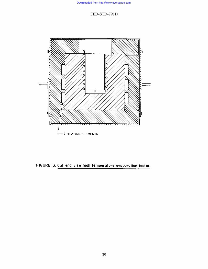
4.1.1 The body and cover of the cell shall be constructed of stainless steel and air-heating coil also of stainless steel.
4.1.2 The sample cups (recommended maximum weight 200 g each), hood, eduction
tube, and orifice shall be constructed of stainless steel. A suitable material is an alloy steel conforming to grade S, type 304, of ASTM A204. To facilitate removal and separation of the cup and hood for inserting the sample and weighing, The sample cup shall be threaded to the hood and this in turn to the eduction tube of the cover. The cover of the cell shall be made air-tight.
4.2. Air supply system, capable of supplying to the cell the required flow of air free of
mechanically entrained particles. A 61.0-cm (24-in) length of 12.7-cm (5-in) diameter pipe, reduced to 2.54-cm (1-in) diameter at each end, packed with glass wool at each end, and filled with a suitable drying agent has been found satisfactory for filtering and drying. Means must be provided for filling the drying and filtering tube.
4.3 Heating blocks of cast aluminum with evaporation cells and air coils cast within.
The heating block shall be heavily insulated and equipped with sufficient electric heating
34
Downloaded from http://www.everyspec.com

FED-STD-791D
elements to maintain the test temperature. There shall be one thermocouple provided for each heating element. Figures 1, 2, and 3 show a satisfactory heating block.
4.4 Temperature controller. A suitable temperature controller capable of maintaining
temperatures between 99° to 538°C " 0.5°C. A suitable temperature recorder shall also be provided.
4.5 Flowmeter. A rotameter calibrated to deliver air at a rate of 2.58 " 0.02 g/min
between 15.6° to 29.4°C (60° and 85°F) (2 L/min at standard temperature and pressure). It shall be furnished with a needle valve and may be mounted as shown in Figure 7.
4.6 Evaporation tester stand. A suitable stand for supporting the test apparatus is shown
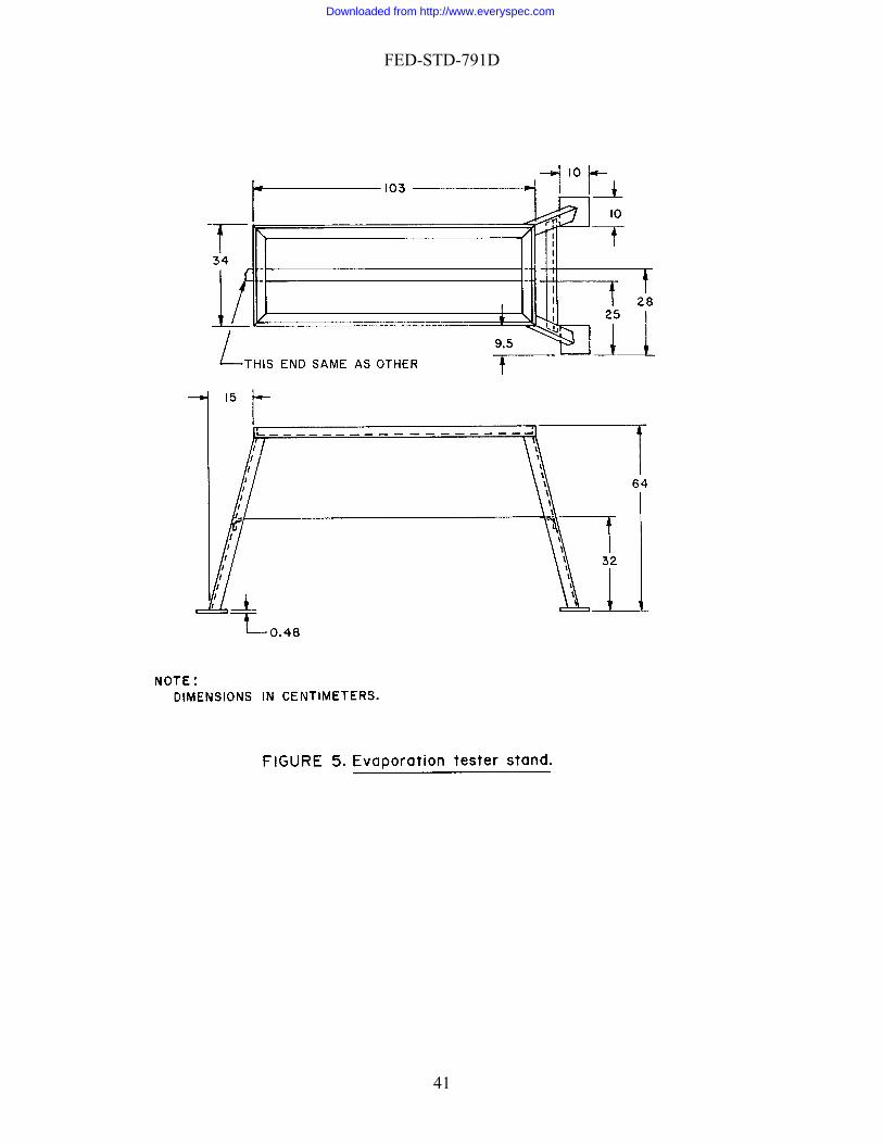
in Figure 5. 5. MATERIALS
5.1 CAUTION - SOME MATERIALS ARE TOXIC AND HAZARDOUS. The materials references and standards listed in this section must be handled carefully. Federal Test Method 10000, Material Handling Safety Precautions, is a reference which lists all toxic and hazardous materials cited in FTMS 791. The synonyms, life hazard, flammability, handling and storage precautions, emergency treatment and measures, and spill practices of each chemical are explained.
5.2 1,1,1-Trichloroethane (ASTM D 4126), [2,1,0]. 5.3 Tissue, Facial.
6. PROCEDURE
6.1 Greases 6.1.1 Clean the grease-sample cup and hood thoroughly, using warm
1,1,1-trichloroethane (38°-54°C [100°-130°F]) and facial tissues. Dry thoroughly in warm air.
NOTE 1: Caution. 1,1,1-trichloroethane is toxic. Use it only in a well ventilated area. Avoid contact with skin.
6.1.2 Weigh the clean grease-sample cup and hood to the nearest mg. Remove the hood
and fill the cup with sample, taking care to avoid occlusion of air. Smooth the surface level with the rim of the cup with a straight edged spatula. Remove with a clean cloth any grease which may remain on the rim or threads of the cup. Thread the hood tightly onto the cup without disturbing the smoothed grease surface. Weigh the assembly and record the net weight of the sample to the nearest mg.
6.1.3 With cover in place, but without the hood and sample cup attached, allow the
evaporation cell to acquire the temperature of the block (controlled to 2°C ["1°F]), at which the
35
Downloaded from http://www.everyspec.com

FED-STD-791D
test is to be made. Allow the block to maintain the temperature of the test at least 2 h before beginning the test. During this period, allow clean air to flow through the cell at the prescribed rate, 2.58 " 0.02 g/min (2 L/min at standard temperature and pressure), as indicated by the rotometer. Then remove the cover, thread the weighed hood and sample cup into place, and replace the cover. Tighten the three knurled cover- tightening screws securely to prevent air leakage under the cover. Pass clean air through cell for 22 h " 5 min.
6.1.4 At the end of the 22-hour period, remove the assembled sample cup and hood from the cell, and allow to cool to room temperature. Determine the net weight of the sample to the nearest mg.
6.2 Oils. 6.2.1 Clean the oil-sample cup and hood as described in 6.1.1. 6.2.2 Weigh the clean oil-sample cup and hood to the nearest mg. Transfer, by means of
a pipet, 10.00 " 0.05 g of sample to the cup. Assemble the cup and hood, being careful not to splash oil on the underside of the hood. Weigh the assembly and record the net sample weight to the nearest mg.
6.2.3 Evaporate the sample as described in 6.1.3 and 6.1.4.
7. CALCULATION
7.1 Calculate the evaporation loss of the sample as follows:
100 * SW-S = weightby percent loss, nEvaporatio
where: S = initial weight of sample, in grams. W = weight of sample, in grams, after the test.
8. REPORTING
8.1 Report the evaporation loss percentage. 9. PRECISION
9.1 Results should not differ from the mean by more than the following amounts:
Repeatability: 2.5% of mean Reproducibility: Not established
Method prepared by:
Navy - NADC – 1986
36
Downloaded from http://www.everyspec.com

FED-STD-791D
37
Downloaded from http://www.everyspec.com

FED-STD-791D
38
Downloaded from http://www.everyspec.com
FED-STD-791D
39
Downloaded from http://www.everyspec.com

FED-STD-791D
40
Downloaded from http://www.everyspec.com
FED-STD-791D
41
Downloaded from http://www.everyspec.com

FED-STD-791D
42
Downloaded from http://www.everyspec.com

FED-STD-791D
43
Downloaded from http://www.everyspec.com

FED-STD-791D
Method 352.1 September 30, 1986
EFFECT OF EVAPORATION ON FLAMMABILITY 1. SCOPE
1.1 This method is used for determining the effect of evaporation on the flammability of a liquid petroleum product. 2. SUMMARY
2.1 It consists of checking the flammability of the liquid (by passing a sample-soaked pipe cleaner repeatedly through a flame and noting the number of passes required for ignition), storing the sample in an oven for the time and at the temperature required by the specification, and rechecking flammability. 3. SAMPLE SIZE
3.1 Approximately 30 mL of liquid to be tested. 4. REFERENCES, STANDARDS, AND APPARATUS
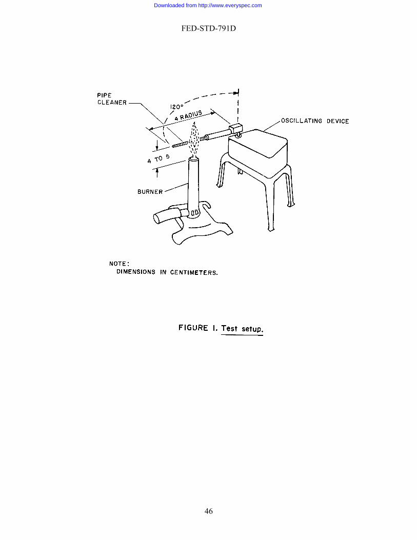
4.1 Oscillating device (such as a windshield wiper), approximately 120° arc at 25 2 cpm.
4.2 Petri dish, approximately 9.0-cm diameter by 1.6-cm deep. 4.3 Oven, gravity-convection, capable of maintaining the specified temperature within
1°C (2°F). 4.4 Bunsen burner.
5. MATERIALS
5.1 CAUTION - SOME MATERIALS ARE TOXIC AND HAZARDOUS. The materials references and standards listed in this section must be handled carefully. Federal Test Method 10000, Material Handling Safety Precautions, is a reference which lists all toxic and hazardous materials cited in FTMS 791. The synonyms, life hazard, flammability, handling and storage precautions, emergency treatment and measures, and spill practices of each chemical are explained.
5.2 Pipe Cleaners (U.S. Tobacco Co., Dill's or equal).
44
Downloaded from http://www.everyspec.com
FED-STD-791D
6. PROCEDURE
6.1 Cut at least ten 5.1-cm (2-in) lengths of pipe cleaner. 6.2 Assemble a test setup (Figure 1) as follows:
a. Mount a 5.1-cm (2-in) piece of pipe cleaner in the arm of the oscillating device so that the end of the pipe cleaner describes an arc of approximately 120° at a radius of 10.2 0.31 cm (4 1/8 in).
b. Adjust the Bunsen burner to provide a completely blue flame approximately 10 cm (4 in) high, and without a sharp inner cone.
c. Position the Bunsen burner so that the center of the 5.1-cm (2-in) piece of pipe cleaner will pass through the center of the flame at the reversing point of the cycle.
6.3 Pour approximately 30 mL of the sample into the petri dish, and soak five 5.1-cm (2-
in) pieces of pipe cleaner in the sample for two min. 6.4 Drain off excess sample from one of the pieces of pipe cleaner, and mount cleaner in
test apparatus as described in paragraph 6.2. Start the oscillating device, and record the number of cycles necessary for a self-sustained flame to appear on the pipe cleaner. Repeat this procedure with four other pieces of pipe cleaner.
6.5 Store the uncovered petri dish containing the sample in the oven, for the specified
time. 6.6 At the end of this time, remove the dish from the oven. Place five 5.1-cm (2-in)
pieces of pipe cleaner in the dish. 6.7 Recheck flammability as specified in 6.4.
7. CALCULATIONS
7.1 This section is not applicable to the test procedure. 8. REPORTING
8.1 Report the average number of cycles necessary for a self-sustaining flame to be achieved on the pipe cleaner both before and after partial evaporation. 9. PRECISION
9.1 Precision data have not been developed for this method.
Method prepared by: Navy - NADC – 1986
45
Downloaded from http://www.everyspec.com
FED-STD-791D
46
Downloaded from http://www.everyspec.com

FED-STD-791D
Method 353.1 September 30, 1986
EVAPORATION
1. SCOPE
1.1 This method is used for determining the tendency of oil to form a hard or tacky residue upon evaporation. 2. SUMMARY
2.1 It consists of heating an oil-coated glass slide in an oven, at the temperature and for the time required by the specification, and reporting the condition of the residue. 3. SAMPLE SIZE
3.1 As needed, usually less than 100 mL. 4. REFERENCES, STANDARDS, AND APPARATUS
4.1 Slide, microscope, glass.
4.2 Oven, gravity-convection, specified temperature within 0.5°C ("1° F).
4.3 Thread or wire, heat-resistant (for suspending slide in oven). 4.4 Beaker, 250 mL (for immersing the slide in the sample).
5. MATERIALS
5.1 This section is not applicable to the test procedure. 6. PROCEDURE
6.1 Heat oven to specified temperature "0.5°C ("1°F). 6.2 Cut notches near one end of slide so that it can conveniently be suspended by a
thread or wire. 6.3 Immerse slide in oil at room temperature. 6.4 Remove slide from oil, and suspend it in oven for the specified time.
47
Downloaded from http://www.everyspec.com
FED-STD-791D
6.5 After the specified heating per d, re ven, and cool it to room io move slide from otemperature. 6.5 After the specified heating period, remove slide from oven,
mperature. 6.6 Observe the condition of oil residue on slide, paying particular attention to note the
any hard or tacky film.
7. CAL
7.1 This section is not applicable to the test procedure.
. REPORTING
attention to the resence of any hard or tacky film.
. PRECISION
9.1 Precision data has not been developed for this method.
Method prepared by:
Navy - NADC - 1985
and cool it to room te
presence of
CULATIONS
8
8.1 Report the condition of the oil residue on the slides, paying particular p 9
48
Downloaded from http://www.everyspec.com

FED-STD-791D
Method 361.4 September 30, 1986
. SCOPE
1.1 This method describes a procedure for evaluating the stroking properties of brake fluids u icles. This method, with slight
odifications, may be used to evaluate hydraulic brake rubber cups against a standard brake
2. SUM
2.1 The method utilizes standard Society of Automotive Engineers (SAE) hydraulic ted in a manner similar to that of an automobile brake system. The test brake
uid is subjected to various stroking rates, pressures, and temperatures designed to evaluate the lubrica ical and physical
sts required by the brake fluid specifications.
2.2 It is essential to have meaningful reference data before a significant interpretation of test results can be made. Reference data must include comparable test influid of known service performance characteristics. . SAMPLE SIZE
3.1 Approximately 3.8 L (1 gal) of the brake fluid to be tested.
. REFERENCES, STANDARDS, AND APPARATUS
4.1 SAE Standard.
J 1703 - Motor Vehicle Brake Fluid
4.2 ASTM Standard. D 2240 - Rubber Property-Durometer Hardness 4.3 Apparatus. 4.3.1 Wheel assemblies.1 Four left front wheel brake assemblies.
STROKING PROPERTIES OF HYDRAULIC BRAKE FLUIDS 1
sed in the hydraulic brake systems of automotive vehmfluid.
MARY
brake parts mounfl
tion properties of the brake fluid. This method complements the chemte
formation on a brake
3
4
1An alternative to the wheel assemblies is described in section 4.12 of SAE J 1703.
49
Downloaded from http://www.everyspec.com

FED-STD-791D
4.3.1.1 Bearing assemblies. Four front outer bearing assemblies, and four front inner bearing assemblies, with bearing races and grease seals.
4.3.1.2 Hub and brake drum assemblies. Four left front wheel hub and brake drum
ssemblies.
.3 Helper springs. One helper spring per wheel assembly.
4.3.2.1 Type of actuating mechanism. The actuating mechanism shall be operated by
re or hydraulic means. Mechanical actuation is not recommended.
4.3.3 Stroking rate and rate-of-load application. The actuating mechanism shall be designe
maximum of 60/40 percent per stroke cycle. "60/40 percent" ratio per stroke cycle indicates that pressure is applied during 60% of the
e cycle, while the pressure is released, or not applied, during the remaining 0% of the cycle.)
4.3.4 Pressure gages. Two recording pressure gages of 0 to 6.9 gage MPa (0 to 1000 shall have a 24-hour cycle, while the
ther gage shall have a maximum cycle of 6 min. Each gage shall be provided with a shut off valve for removing air from the connecting tubing.
nical or electrical revolution counter with recording
apacity for 500,000 strokes.
.3.6 Tubing. Approximately 4.6 m (15 ft) of 0.63 cm (1/4 in) O.D. copper or steel tubing fittings.
stand or frame for mounting the four left front wheel assemblies as shown in Figure 1.
4.3.8 Cabinet or oven. A large cabinet or oven, of sufficient capacity to house the stand with
the four mounted wheel assemblies, together with the master cylinder and necessary connec
a
4.3.1
4.3.2 Brake pressure actuating mechanism. A suitable actuating mechanism for applying pressure to the master cylinder push rod to simulate, as closely as possible, the braking operation in a vehicle.
suitable air pressu
4.3.2.2 Pressure application. The amount of pressure applied by the actuating mechanism shall be adjustable. The mechanism shall be capable of applying sufficient thrust to the master cylinder to create a minimum pressure of 6.9 gage MPa (1000 psig) in the simulated brake system.
d to permit adjustable stroking rates ranging from 500 to 1,000 strokes per hour as desired. The ratio of percent time-of-load application to non-load application shall also be adjustable, from a minimum ratio 25/75 percent to a(Aduration of the strok4
psig) capacity with connecting tubing. One of the gageso
4.3.5 Revolution counter. A mechac
4with inverted flare nuts, connectors, adaptors, and 4.3.7 Stand. A
tions.
50
Downloaded from http://www.everyspec.com
FED-STD-791D
4.3.9 Temperature control. The cabinet or oven shall be insulated, and shall be equipped with suitable means of heating and cooling to provide the specified test temperatures. The temperatures shall be thermostatically controlled within "2.8°C ("5°F) of the specified test temper
.3.10 Durometer, Type A-shore durometer. The description of the durometer, calibrat STM D 2240. 5. MA
CAUTION - SOME MATERIALS ARE TOXIC AND HAZARDOUS. The chemical materials listed in this section must be handled carefully. Federal Test Method 10000, Materia
recautions, emergency treatment and measures, and spill practices of each chemical are explained.
cus cloth. Crocus cloth shall conform to the requirements of ANSI B74.18.
t number RM-15a.
.7 Wheel cylinder pistons. Unanodized aluminum pistons (SAE RM-12) made from SAE A
.8 Master cylinder piston. Use a SAE RM-13 piston made from SAE CA 360 copper-
NOTE:
ature. 4ion, and application in testing rubber hardness may be found in A
TERIALS
5.1
l Handling Safety Precautions, is a reference which lists all toxic and hazardous materials cited in FTMS 791. The synonyms, life hazard, flammability, handling and storage p
5.2 Ethyl alcohol, (ACS) [0, 3, 0]. 5.3 Cro 5.4 Wheel cylinder assemblies. Four cast iron housing straight bore hydraulic brake
wheel cylinders having a diameter of approximately 2.8 cm (1-1/8 in). SAE part number RM-14a.
5.5 Master cylinder assembly. One cast iron housing hydraulic brake master cylinder
having a diameter of approximately 2.8 cm (1-1/8 in.) and fitted with an uncoated steel standpipe. SAE par
5.6 Rubber cups. All wheel cylinder and master cylinder cups used in the test brake
system shall be made of SBR type elastomer. SAE part numbers for wheel cylinders and master cylinders are RM-3, RM-4 and RM-5.
5A 2024 aluminum alloy are to be used. 5base alloy (half hard).
All standard SAE parts are available from the Society of Automotive Engineers, Inc,
400 Commonwealth Drive, Warrendale, PA 15096. 6. PROCEDURE.
6.1 Preparation of the test apparatus.
6.1.1 Inspection and cleaning of parts.
51
Downloaded from http://www.everyspec.com

FED-STD-791D
6.1.1.1 Wheel cylinder assemblies. The wheel cylinder assemblies shall be completely disassembled. All rubber parts, with the exception of the cylinder boots, shall be discarded. The expanders in the assembly shall also be discarded. All metal parts shall be cleaned with 95% ethyl alcohol to remove preservative oils, grease, and dirt, then dried in a stream of dry air, and examined for cuts, scores, galling, or pitting. Any part having any of these flaws shall be replace
shall be iscarded.
6.1.1.2 Master cylinder assemblies. The master cylinder assemblies shall be completely disasse
a burring tool or a jeweler's file.
.1.1.3 Rubber parts. The rubber parts to be used in the test shall be cleaned with a lint-fre f dry air and examined for cuts, molding flaws, or blisters. Any deficient part shall be discarded.
d dried by blowing dry air through it, prior to connecting to the test apparatus.
iameter of the master cylinder and of each of the wheel cylinders shall be measured with a micrometer, to the nearest 0.0025 cm (0.001 in). Four reading
), the cylinder in question shall be discarded.
a micrometer, to the nearest 0.0025 cm (0.001 in). Two readings, at right angles to each other, shall be taken on each piston, and their average conside
in question shall be discarded.
within the c ess than 0.0075 cm (0.003 in) or m (0.005 in), the cylinder or the piston shall be replaced by another similar
art.
.2.3 Rubber cups.
d. Light stains on the cylinder walls shall be removed by rubbing with crocus cloth and 95% ethyl alcohol. Any cylinder which cannot be freed of stains by this procedured
mbled. All rubber parts, including the piston washer if it forms an integral part of the primary cup, shall be discarded. The metal parts shall be cleaned, air-dried, examined for flaws, and light stains removed from the cylinder walls in the manner specified for the wheel cylinder assemblies (see 6.1.1.1). Any deficient parts shall be replaced. The cylinder's relief and supply parts shall be inspected for burrs and wire-edge. If present, they may be removed with
6e cloth and 95% ethyl alcohol to remove all dirt and grease, then dried in a stream o
6.1.1.4 Tubing. The tubing used as brake fluid lines shall be flushed with 95% ethyl
alcohol, an 6.2 Initial measurements and tolerance. 6.2.1 Cylinders. The internal d
s, approximately 45° apart, shall be taken on each cylinder, and their average considered as the diameter of the cylinder. If the largest and smallest diametrical readings differ from each other by more than 0.0075 cm (0.003 in
6.2.2 Pistons. The external diameter of the master cylinder piston and of each of the
wheel cylinder pistons shall be measured with
red as the diameter of the piston. If the two readings differ from each other by more than 0.0025 cm (0.001 in) the piston
6.2.2.1 Clearance of piston in cylinder. Each piston shall be checked for clearance ylinder for which it is intended. If the clearance is l
more than 0.0125 cp
6
52
Downloaded from http://www.everyspec.com

FED-STD-791D
6.2.3.1 Base and lip diameters of the cups. The internal base and lip diameters of each rubber cup shall be determined with a micrometer, to the nearest 0.0025 cm (0.001 in). The cups shall be placed on a flat surface for 24 h before measuring. In measuring the diameters of the cups, care should be taken that the micrometer does not extend more than 0.08 cm (1/32 in) beyond the edges of the cup. If difficulty is encountered in measuring the diameter of the master cylinder secondary cup, the cup may be placed on a mandrel having a slight taper. Two readings at right angles to each other, shall be taken on the base and lip of each cup, and their average considered as the base and lip diameters of the cup. If the two readings on the base or the two readings on the lip differ by more than 0.0025 cm (0.001 in) respectively, the cup in question shall be
e back edge of the durometer is placed on the shelf of the fixture, with the bottom e durometer kept parallel to the surface of the base of the cup. The durome
d so that the pressure plate makes firm contact with the surface of the cup. The durometer reading is taken a
served, with the reading estimated to the nearest whole point of the dial scale.
.2.3.2.1 Wheel cylinder cups. The average durometer hardness of the wheel cylinder cups sh
.3 Assembling, adjusting, and checking the apparatus.
ers shall be checked for ease of operation, and then installed in their respective places in the simulated brake systems. Helper springs
6.3.2 Shoe clearance adjustment. The brake shall be adjusted to have a clearance of 0.102 " .0075 cm (0.040 " 0.003 in) between the shoe and the drum, at the toe.
6.3.3 Filling and bleeding the brake system. The assembled simulated brake system shall be filled with the fluid under test by means of a pressure pot, or by hand. If filled by hand
discarded. 6.2.3.2 Hardness of rubber. The durometer hardness of each cup shall be measured at
four different points near the center of each cup. The average of the four readings shall be considered as the hardness of the rubber cup. For the sake of uniformity the durometer readings should be made as follows: The proper rubber anvil is inserted in the fixture, and the rubber cup placed on the anvil. Th
surface of thter is grasped between the thumb and the third and fourth fingers of one hand, with the
index finger placed on the top of the depressor. The indentor point is lowered gently until it rests on the surface of the cup. With a minimum amount of rocking, pressure is then applie
s soon as the dial needle comes to rest. If the needle does not come to rest, then the reading is taken at that moment when a definite change in the speed of the needle is ob
6all be 60 " 3 points. Nonconforming cups shall be discarded. 6.2.3.2.2 Master cylinder cups. The average durometer hardness of the master cylinder
cups shall be 63 " 3 points. Nonconforming cups shall be discarded. 6 6.3.1 Assembly of brake parts. After the required measurements have been taken and
recorded, the wheel cylinders and the master cylinder shall be assembled for test. All parts with the exception of the cylinder housings and the rubber boots, shall be dipped in the hydraulic fluid under test when they are assembled. The assembled cylind
shall be installed in holes beneath the shoe flanges, pushed up and hooked over the flanges (see Figure 1).
0
53
Downloaded from http://www.everyspec.com

FED-STD-791D
the ma
level. A constant level of test fluid shall be maintained at the master cylinder throughout the test. Accurate record shall be kept of the number of mL of the fluid added to the system
psig) and recorded. The pressure stroke pattern shall be adjusted at 60/of the s
test. The pressure stroke pattern shall be compared with the initial pattern at intervals of 50,000 strokes during the test.
.4.1.2 Brake-in or burnishing run. The stroking rate shall be adjusted at 1,000 50 strokes
n of test. The test shall be run until 94,000 strokes have been completed. The nu
ster cylinder shall be stroked several times to completely fill the system. All the wheel cylinders and the tubing connected to the pressure gages shall be bled to remove the entrapped air from the system.
6.3.4 Checking the system for leaks. After the system has been bled, a pressure of 6.9
gage MPa (1,000 psig) shall be applied to the system. The system shall be slowly stroked for 10 min, after which an inspection shall be made for leaks. The pressure shall be released, and the brake shoe clearance rechecked (6.3.2).
6.3.5 Fluid
during the test. It may be necessary to install special antisplash plugs on the master cylinder reservoir to avoid loss of the fluid due to splashing.
6.4 Test procedure. 6.4.1 Procedure A. Stroking properties at high temperatures. 6.4.1.1 Conditions of test. 6.4.1.1.1 Test temperature. Unless otherwise specified the test temperature shall be 120°
" 3°C (248° " 5°F). The test shall be started at room temperature (23° " 5°C). The rise in temperature from room temperature to the test temperature shall take place in not more than 8 h from the start of the test.
6.4.1.1.2 Pressure. The initial stroking pressure in the simulated brake system shall be
adjusted at room temperature (23° " 5°C), to 3.4 gage MPa (50040 percent stroke ratio 17 strokes/min, with the aid
hort-cycle pressure recorder, so as to produce a relatively smooth curve (see Figure 2). Accurate record shall be kept of any pressure variations during the
6 " per hour, using the 60/40 percent stroke ratio and the stroking pressure of 3.4 MPa gage
(500 psig) applied at room temperature (23° " 5°C). While at room temperature, the system shall be stroked 16,000 " 500 strokes. At the end of this stroking period the system shall be checked for fluid level. The cylinder shall be filled to the given level, if necessary, and the test resumed.
.4.1.3 Duratio6
mber of strokes given in the burnishing run (see 6.4.1.2) and in coming to test temperature (see 6.4.1.1.1) shall be included as part of total 94,000 strokes. The number of strokes required, if other then 94,000 shall be specified in the material specification.
6.4.2 Procedure B. Stroking properties at sub-zero temperatures.
54
Downloaded from http://www.everyspec.com
FED-STD-791D
6.4.2.1 Conditions of test. 6.4.2.1.1 Test temperature. The test temperature shall be -40° " 3°C (-40° " 5°F) or -
55° " 3 C (-67° 5°F), as specified. The test shall be started at room temperature (23° 5°C).
troking pressure in the simulated brake system shall be adjusted at room
burnishing run. The stroking rate shall be adjusted at 1,000 " 50 strokes/h, using the stroking pressure of 3.4 gage MPa (500 " 10 psig) applied at room temper ll be stroked 16,000 " 500 strokes, at the end of which th and proper brake shoe clearan checked for fluid level. The cylinder shall be filled to the given level, ing rate shall then be adjusted to 720 " 50 strokes/h, using a 40/60 p
n.
.1.2 Functioning of wheel cylinder pistons. The functioning of the wheel cylinder pistons shall be observed. Improper functioning of the pistons, such as freezing of the piston in the cyl
er functioning of the wheel cylinder pistons. If inspection of the malfunction shows this to be the case, the test shall be repeate
° " "The drop in temperature from room temperature to the specified test temperature shall take place in from 8 to 24 h, following the start of the test.
6.4.2.1.2 Pressure. The initial s
temperature (23° " 5°C) to 3.4 gage MPa (500 psig), and recorded. The pressure stroke pattern shall be adjusted at 60/40 percent stroke ratio, with the air of the short cycle pressure recorder so as to produce a relatively smooth curve (see Figure 2). Accurate record shall be kept of any pressure variations during the test.
6.4.2.2 Break-in or
ature (23° " 5°C). While at room temperature the system shae system shall be checked for leaks,
ce and the master cylinder if necessary. The strok
ercent stroke ratio. The pressure-stroke pattern shall be adjusted, with the aid of the short-cycle pressure recorder, to give a relatively smooth curve (see Figure 3). Accurate record of observed pressure variations shall be compared with the initial pattern at approximately every 20,000 strokes. The stroking cycle, if other than that listed in this paragraph, shall be specified in the p oduct specificatior
6.4.2.3 Duration of test. The test shall be run until 94,000 strokes have been completed.
The number of strokes given in the burnishing run (see 6.4.2.2) and in coming to the specified test temperature shall be included as part of the total 94,000 strokes. The number of strokes required, if other than 94,000, shall be specified in the product specification.
.5 Observations. 6
6.5.1 Observations during test. 6.5.1.1 Pressure change. Observations at 12-hour intervals shall be made of the stroking
pressure in the simulated system, to determine changes from the initial pressure. 6.5
inder, or failure of the brake shoe to be released from the brake drum, shall be recorded. However, very slight drag of the brake shoe on the drum, when the drum is rotated by hand, shall not be considered as improper functioning of the cylinder pistons. Mechanical defects of the brake mechanism may cause excessive pressure rise or improp
d using new parts.
55
Downloaded from http://www.everyspec.com

FED-STD-791D
6.5.1.3 Leakage (or evaporation). The leakage (or evaporation) loss of the hydraulic brake fluid at 24,000-stroke intervals shall be determined by the mL of the fluid required to maintai
en be re-examined for evidence of corrosive action, such as pitting, etching, and severe stain.
and of the master cylinder shall be measured as specified in 6.2.1.
iameter of the master cylinder piston and of each wheel cylinde cified in 6.2.2.
determined as specified in 6.2.3.2. The diam
n the constant fluid level in the master cylinder reservoir. The level of the fluid should be checked daily.
6.6 Observations and measurements at end of test. 6.6.1 Leakage. The equipment shall be allowed to come to room temperature within 16
h following completion of the required number of strokes. The brake wheel cylinder shall be examined for evidence of excessive leakage. The assembly shall then be stroked an additional 100 strokes at 3.4 gage MPa (500 psig), and the cylinders again examined for evidence of excessive leakage.
6.6.2 Disassembly of cylinders. The wheel cylinders and the master cylinder shall be
removed from the simulated system. The inlet ports of the cylinders shall be plugged or capped immediately upon removal to retain the fluid remaining therein. Each cylinder shall then be carefully disassembled. The fluid remaining in the cylinder shall be drained into a small screwcap jar, and saved for examination for evidence of sludging, jelling, sedimentation, and grittiness.
6.6.3 Inspection. A visual inspection of the disassembled cylinder shall be made, and a
record made of the type and quantity of dirt; gum deposition; rusty, scored, and galled areas on the surface of the pistons and on the cylinder walls; chipping, scoring, and general condition of the rubber cups. All parts shall then be cleaned with 95% ethyl alcohol, and dried in a stream of air. The metal parts shall th
6.6.4 Measurements. 6.6.4.1 Cylinders. The internal diameter of each wheel cylinder
6.6.4.2 Pistons. The external dr piston shall be measured as spe 6.6.4.3 Rubber cups. Measurements of the base and lip diameters of the rubber cups
shall be made as specified in 6.2.3.1. Durometer hardness of the cups shall beeter measurements and the hardness determinations shall be made
within 1 h following removal from the cylinder assembly. 7. CALCULATIONS
7.1 Change in cylinder and piston diameter:
56
Downloaded from http://www.everyspec.com
FED-STD-791D
C - C = C 21
where: C = C1 = original cylinder bore diameter. C =
where: P = cha
change in cylinder diameter.
2 final cylinder bore diameter.
P-P=P 21
nge in piston diameter. P1 = original piston diameter. P2 = final piston diameter.
7.2 Change in base and lip diameter of rubber cups.
-B=B B12
where: B = change in rubber cup base diameter. BB1 = original base diameter. B2B r.
L = change in rubber cup lip diam
wheLDIS = lip dL1 = original lip diameter of rubber cup. L2 = final lip diameter of rubber cup. C1 = original cylinder bore diameter.
= final base diamete
L-L=L 12
where:
eter. L1 = original lip diameter. L2 = final lip diameter.
7.3 Lip diameter interference set.
100 * - L - L = LDIS 21
CL 11
re:
iameter interference set percentage.
57
Downloaded from http://www.everyspec.com

FED-STD-791D
7.4 Change hardness of rubber cup.
H2 = final hardness value.
7.5 Change in fluid pressure.
= change in system pressure. P1 = orP2 = final pressure value.
7.6 Change in fluid volume
V = change in fluid volume. V1 = original volume. V2 = final volume.
RTING
mmary of the test conditions and the inspection results shall be made stroking test. Reports shall be made on the following:
a ssive) of corrosion, scoring, and galling of metal parts. b. Change in the initial diameter of the cylinders and pistons (see 7.1). c. Change in the base and lip diameters of the rubber cups (see 7.2). d. Percentage of lip diameter interference set (see 7.3). e. Change in the durometer hardness of rubber cups (see 7.4). f. Degree (slight, moderate, or excessive) of swelling, tackiness, scoring, scuffing, or
istering of the rubber cups. h successive 12-hour interval (see 7.5). evaporation, at the end of each successive
st (see 7.6). nd of the test (see 6.2.1 and 7.6).
H-H=H 12
where: H = change in durometer hardness. H1 = original hardness value.
P-P=P 12
where: P
iginal pressure value.
V-V=V 12
where:
8. REPO
8.1 Summary. A suat the completion of the
. Degree (slight, moderate, or exce
blg. Pressure change in the system at end of eac
age or h. Volume loss of fluid due to leake te24,000-stroke interval during th
i. Volume loss of the fluid at the e
58
Downloaded from http://www.everyspec.com
FED-STD-791D
j. ive) of sludging, jelling, sedimentation, or grittiness of the fluid after testing (see 6.2.2).
k. Observed improper functioning of the wheel cylinder pistons. . PRECISION
show the same general trend for a given hydraulic brake
flu leakage during and after test, excessive increase in the stroking pre ning of the wheel cylinder pistons.
using new parts if mechanical difficulties, which cannot be
attributed to the fluid proper, are encountered during the test.
Method Prepared By:
Army - ME - 1986
Degree (slight, moderate, or excess
9
9.1 Duplicate test runs should id, particularly in the matter ofssure, and improper functio
9.2 The test shall be repeated
59
Downloaded from http://www.everyspec.com

FED-STD-791D
60
Downloaded from http://www.everyspec.com

FED-STD-791D
61
Downloaded from http://www.everyspec.com
FED-STD-791D
Method 550.1
4.6 Graduated cylinder, 100-mL capacity.
. MATERIALS
5.1 CAUTION - SOME MATERIALS ARE TOXIC AND HAZARDOUS. The hemical materials listed in this section must be handled carefully. Federal Test Method 10000, aterial Handling Safety Precautions, is a reference which lists all toxic and hazardous materials
ited in FTMS 791. The synonyms, life hazard, flammability, handling and storage precautions,
September 30, 1986
EMULSIFICATION TENDENCIES OF PETROLEUM FUELS BY MULTIPLE CONTACT EXTRACTIONS
1. SCOPE
1.1 This method is used for determining the emulsification tendencies of petroleum fuels resulting from contact with the water bottoms usually found in fuel storage environments. 2. SUMMARY
2.1 A sample composed of water and test fuel is placed in a sealed bottle and subjected to a cycle consisting of shaking, settling, rating, siphoning, and addition of fresh fuel. Theappearance of the fuel-water interface is reported after the settling period. A total of ten complete cycles is required. 3. SAMPLE SIZE
3.1 Approximately 1.1 L of the fuel to be tested. 4. REFERENCES, STANDARDS, AND APPARATUS
4.1 Bottle, oil sample, 125 mL capacity (Kimble No. 60520L or equal), with No. 24 plastic screw cap.
4.2 Gasket material, fluorocarbon vulcanizate (Viton or equal), 0.16-cm thick sheet
stock, cut to the I.D. of the No. 24 screw cap (approximately 2.1 cm). 4.3 Syringe, B.D., Luer-Lok, 100-mL capacity. 4.4 Syringe needle, Teflon (or equal), with Kel-F (or equal) hub, 16-gauge, 30.5-cm
(12-in.) length (Hamilton No. KF16TF or equal). 4.5 Mechanical reciprocating shaker device (Equipoise Heavy-Duty or equal).
5
cMc
62
Downloaded from http://www.everyspec.com
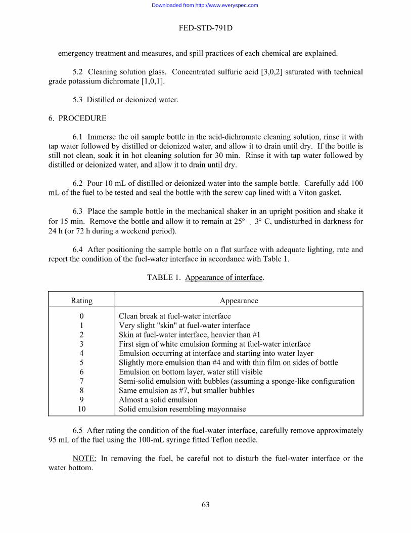
FED-STD-791D
emergency treatment and measures, and spill practices of each chemical are explained.
5.2 Cleaning solution glass. Concentrated sulfuric acid [3,0,2] saturated with technical rade potassium dichromate [1,0,1].
5.3 Distilled or d
URE
ottle is ill not clean, soak it in hot cleaning solution for 30 min. Rinse it with tap water followed by
ized water, and allow it to drain until dry.
bottle in the mechanical shaker in an upright position and shake it r 15 min. Remove the bottle and allow it to remain at 25° 3° C, undisturbed in darkness for
a weekend period).
port the condition of the fuel-water interface in accordance with Table 1.
TABLE 1. Appearance of interface
g
eionized water. 6. PROCED
6.1 Immerse the oil sample bottle in the acid-dichromate cleaning solution, rinse it with tap water followed by distilled or deionized water, and allow it to drain until dry. If the bstdistilled or deion
6.2 Pour 10 mL of distilled or deionized water into the sample bottle. Carefully add 100 mL of the fuel to be tested and seal the bottle with the screw cap lined with a Viton gasket.
6.3 Place the sample
fo24 h (or 72 h during
6.4 After positioning the sample bottle on a flat surface with adequate lighting, rate and re .
Appearance
Rating
g at fuel-water interface
ater still visible
ayonnaise
0 1
Clean break at fuel-water interface Very slight "skin" at fuel-water interface
2 3
Skin at fuel-water interface, heavier than #1 First sign of white emulsion formin
4 5 6
Emulsion occurring at interface and starting into water layer Slightly more emulsion than #4 and with thin film on sides of bottle Emulsion on bottom layer, w
7 8
Semi-solid emulsion with bubbles (assuming a sponge-like configuration Same emulsion as #7, but smaller bubbles
9 10
Almost a solid emulsion Solid emulsion resembling m
6.5 After rating the condition of the fuel-water interface, carefully remove approximately
95 mL of the fuel using the 100-mL syringe fitted Teflon needle.
NOTE: In removing the fuel, be careful not to disturb the fuel-water interface or the water bottom.
63
Downloaded from http://www.everyspec.com

FED-STD-791D
6.6 Carefully add a fresh 95-mL sample of the fuel to be tested and seal the sample bottle ith the plastic screw cap as before.
ing, rating, and siphoning steps as described in 6.3 through 6.6 until ten cycles (or extractions) have been performed. . CALCULATIONS
7.1 This section is not applicable to the test procedure.
rating of 3 or greater, denoting the presenc of water-reactive impurities is considered unsatisfactory. The initial formation of these stable i
9. PRECISION
Army - ME - 1986
w 6.7 Repeat the shaking, settl
7
8. REPORTING
8.1 Report interface ratings as measured above. Aenterfacial emulsions are indicative of potential filter-plugging and storage problems.
9.1 Precision data have not been developed for this method.
Method Prepared By:
64
Downloaded from http://www.everyspec.com
FED-STD-791D
September 30, 1986
D
speed or rate of heat removal rovided by quenching oils.
. SUMMARY.
il is alculated.
. SAMPLE SIZE.
3.1 Approximately 4.5 L (1.2 gal) of quenching oil to be tested.
4. REFERENCES, STANDARDS, AND APPARATUS
4.1 One electric timer, graduated in 1/10 seconds. 4.2 Two containers, insulated with 5.1 cm (2 in) of insulation, approximately 30.5 cm
2 in) deep and 11.4 cm (4-1/2 in) wide (inside dimensions). 4.3 One stirrer, electric, of proper size to stir contents of containers. 4.4 One thermometer, 0°-100°C, with 1/10° graduations. 4.5 One furnace, controlled atmosphere, capable of being controlled at 816° 14°C
500° 25°F). 4.6 One hook, steel, approximately 0.64 cm (1/4 in) diameter by approximately 1.2 m (4
) long (to lift and carry test bars).
. MATERIALS
5.1 CAUTION - SOME MATERIALS ARE TOXIC AND HAZARDOUS. The hemical materials listed in this section must be handled carefully. Federal Test Method 10000, aterial Handling Safety Precautions, is a reference which lists all toxic and hazardous materials
ited in FTMS 791. The synonyms, life hazard, flammability, handling and storage precautions, mergency treatment and measures, and spill practices of each chemical are explained.
Method 1110.2
QUENCHING SPEE 1. SCOPE
1.1 This method is used to determine the quenchingp 2
2.1 The test consists of immersing heated steel test bars in samples of the test quench oil. From temperatures recorded during the test procedure the quenching speed of the oc 3
(1
(1
ft 5
cMce
65
Downloaded from http://www.everyspec.com
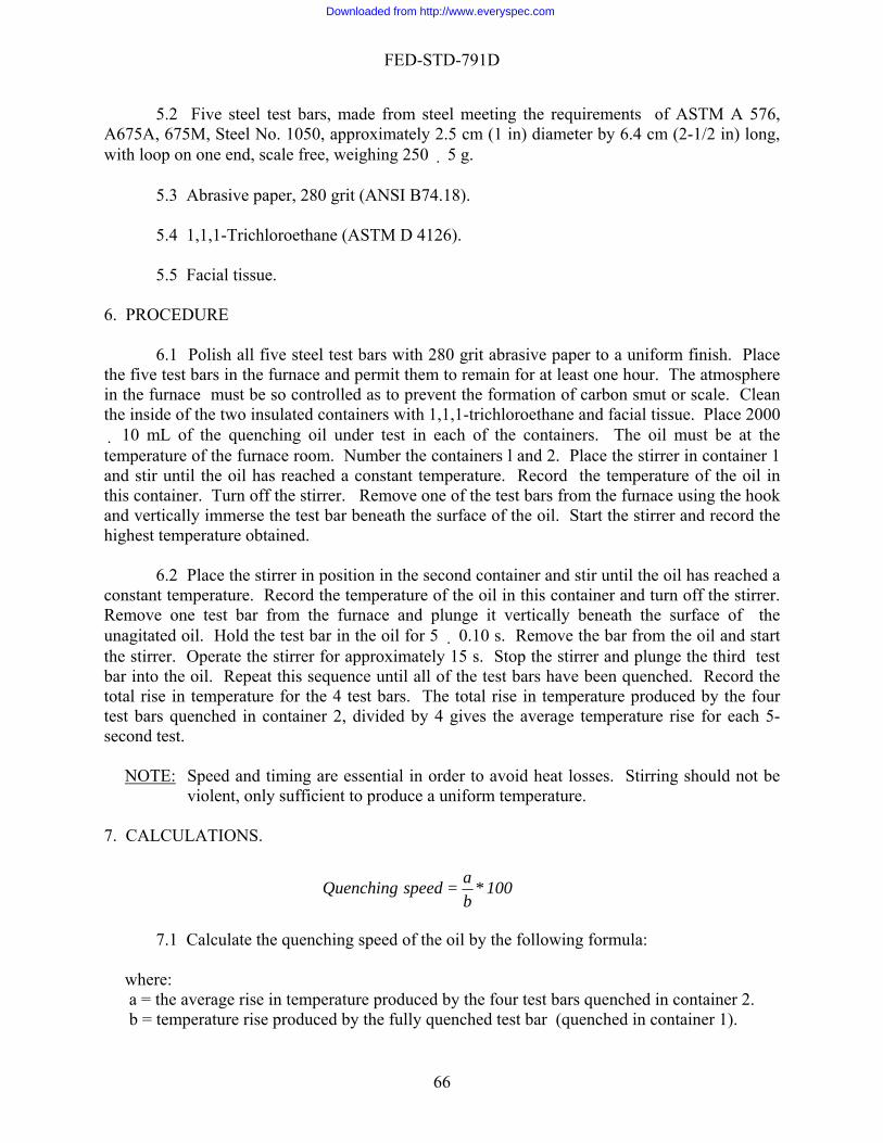
FED-STD-791D
5.2 Five steel test bars, made from steel meeting the requirements of ASTM A 576, long,
with loop on one end, scale free, weighing 250 5 g. 5.3 Abrasive paper, 280 grit
1,1,1-Trichloroethane (ASTM D 4126).
. PROCEDURE
6.1 Polish all five steel test bars with 280 grit abrasive paper to a uniform finish. Place the five
the two insulated containers with 1,1,1-trichloroethane and facial tissue. Place 2000 10 mL of the quenching oil under test in each of the containers. The oil must be at the
rnace room. Number the containers l and 2. Place the stirrer in container 1 nd stir until the oil has reached a constant temperature. Record the temperature of the oil in
this con e furnace using the hook nd vertically immerse the test bar beneath the surface of the oil. Start the stirrer and record the
iner and stir until the oil has reached a
constan Record the temperature of the oil in this container and turn off the stirrer. Remov
ove the bar from the oil and start the stirrer. Operate the stirrer for approximately 15 s. Stop the stirrer and plunge the third test bar into enched. Record the total rise in temperature for the 4 test bars. The total rise in temperature produced by the four test bar e temperature rise for each 5-second test.
A675A, 675M, Steel No. 1050, approximately 2.5 cm (1 in) diameter by 6.4 cm (2-1/2 in)
(ANSI B74.18).
5.4
5.5 Facial tissue. 6
test bars in the furnace and permit them to remain for at least one hour. The atmosphere in the furnace must be so controlled as to prevent the formation of carbon smut or scale. Clean the inside oftemperature of the fua
tainer. Turn off the stirrer. Remove one of the test bars from thahighest temperature obtained.
6.2 Place the stirrer in position in the second contat temperature.e one test bar from the furnace and plunge it vertically beneath the surface of the
unagitated oil. Hold the test bar in the oil for 5 0.10 s. Rem
the oil. Repeat this sequence until all of the test bars have been qu
s quenched in container 2, divided by 4 gives the averag
NOTE: Speed and timing are essential in order to avoid heat losses. Stirring should not be violent, only sufficient to produce a uniform temperature.
ner 2. b = temperature rise produced by the fully quenched test bar (quenched in container 1).
7. CALCULATIONS.
100 * ba = speedQuenching
7.1 Calculate the quenching speed of the oil by the following formula:
where: a = the average rise in temperature produced by the four test bars quenched in contai
66
Downloaded from http://www.everyspec.com
FED-STD-791D
8. REP
he test oil. 9. Prec
or this method.
Method Prepared By:
Army - AR - 1986
ORTING
8.1 Report the calculated quenching speed of t
ision
9.1 Precision data have not been developed f
67
Downloaded from http://www.everyspec.com

FED-STD-791D
Method 1151.2 September 30, 1986
EXPLOSIVE VAPORS IN BOILER FUEL OIL
. SCOPE
1.1 This method is used for determining the approximate percent explosiveness of gas and vapor mixture given off by fuel oil. 2. SUMMARY
2.1 The test consists of measuring the explosiveness of fuel-oil vapors produced under ecified conditions, using a hot-wire type combustible-gas indicator that has been calibrated
gainst a hydrocarbon gas of known explosiveness.
. SAMPLE SIZE
3.1 Approximately 1 L (1 qt) of oil representative of the lot to be tested.
CAUTION:
1
spa 3
The one sample is to have been immediately stoppered (allowing a minimum
of air space) upon removal from the lot.
. REFERENCES, STANDARDS, AND APPARATUS
4.l Indicator, combustible-gas, hot-wire (Explosimeter Model No. 2, Mine Safety ppliances Co., Pittsburgh, Pa., or equivalent).
4.2 Flask, volumetric, 2 L, with 2-hole rubber stopper. 4.3 Graduated cylinder, 100 mL. 4.4 Tank, water (deep enough to accommodate 2-L volumetric flask and 100-mL
raduated cylinder.). 4.5 Tube, drying, containing anhydrous calcium chloride. 4.6 Bulb, aspirator.
4.7 Vapor generating apparatus (Figure 1), consisting of:
a. Bottles (2), glass, 1 qt, wide mouth. b. Stopper, rubber, 2-hole (for 1-qt bottle). c. Stopper, rubber, 3-hole (for 1-qt bottle). d. Thermometer, 40° to 82°C (100° to 180°F) (ASTM El).
4
A
g
68
Downloaded from http://www.everyspec.com

FED-STD-791D
e. Tube, outlet, copper, approximately 3/16-in O.D., sealed at one end with approxim ly 1/ -i h 1/2 i from aled e d.
f. Tubing, glass and rubber, as required. g. Clamp, s 66° to 69°C (150° to
155°F).
4.9 Compressed-air supply.
UTION - SOME MATERIALS ARE TOXIC AND HAZARDOUS. The hemical materials listed in this section must be handled carefully. Federal Test Method 10000,
Materia
es of each chemical are explained.
rocarbon, with known lower limit of explosiveness (in volume percentage of as concentration).
. PROCEDURE
6.1 Prep olumetric flask) by inserting a short
ngth of glass tubing in one hole and the sealed end of the copper outlet tube, used in figure l, in seals the side opening of the tube; seal
e outside end of the glass tube with a short length of rubber tubing and a screw clamp.
0% explosiveness (for use in calibrating the combustible-gas indicator), as follows:
a Compute the volume of hydrocarbon gas (see. 5.2) required to produce a 2-L air-gas ess.
b. Place approximately 500 mL of water in the 2-L volumetric flask, and invert in the
required amount of hydrocarbon gas, using an inverted water-filled 100-mL graduated cylinder supported in the water tank so it will contain the computed
e tank are the same. d. Transfer the gas to the volumetric flask by carefully raising the lip of the graduate
the submerged flask. e. Add air to the volumetric flask until the water levels (inside and outside) are at the
f. Insert the prepared 2-hole stopper (see 6.1) into the volumetric flask taking care to a Remove the flask from the tank and invert
-gas mixture through the
indicator and noting the reading as follows:
ate 8 n ole, n se n
crew (for rubber tubing). Bath heating, water,
5. MATERIALS
5.1 CAc
l Handling Safety Precautions, is a reference which lists all toxic and hazardous materials cited in FTMS 791. The synonyms, life hazard, flammability, handling and storage precautions, emergency treatment and measures, and spill practic
5.2 Gas, hydg
6
are the 2-hole rubber stopper (for the vlethe other hole. Position the outlet tube so that the stopperth
6.2 Prepare an air-gas mixture of 5
. mixture of 50-percent explosiven
water tank. c. Measure the
volume of gas when the water levels in the graduate and th
beneath the neck of
graduation mark.
m intain the water seal of the gas mixture.several times.
6.3 Calibrate the combustible-gas indicator by passing the air
69
Downloaded from http://www.everyspec.com
FED-STD-791D
a. Fill one of the quart bottles about half full of water, and insert its 2-hole stopper (and ) as indicated for bottle A of Figure 1. tubing
ubing on the volumetric flask.
combustible-gas indicator. Adjust the indicator needle to zero. eposition the copper outlet tube so that its side opening is exposed to the air-gas
sure air to the water-filled bottle. e. Adjust the screw clamp to produce a uniform flow of water of approximately 500 mL in
record reading at which the indicator becomes stable.
be with a short length of rubber tubing and a screw clamp. Position the thermometer so that its
e bottle (containing the sample) in the heating bath so that the level of the sample is below the level of the bath, and allow the sample to reach approximately 52°C
During the immersion (approximately 5 min) shake occasionally to insure even heating.
d shake vigorously for a total of 5 min, with periodic immersions of the bottle in the water bath
e-half full of water at about 52°C (125°F) and as soon as bottle B has been shaken for 5 min, connect the two bottles as shown in Figure 1.
pose its opening to the vapors in the bottle.
just the screw clamp to permit the water to flow into the sample-filled bottle
b. Connect the water-filled bottle to the rubber tc. Connect the copper outlet tube to the drying tube, and the drying tube to the
d. Rmixture, and apply low-pres
20 s, and
6.4 Prepare the sample as follows:
a. Fill one of the quart bottles (bottle B) half full of test sample. b. Insert the 3-hole stopper with its inlet tube, outlet tube, and thermometer. Position the
outlet tube so that its side opening is covered by the stopper. Seal the inlet tu
bulb is approximately centered in the test sample. c. Immerse th
(125°F).
6.5 Test the explosiveness of the gas and vapor mixture of the sample as follows:
a. When the temperature of the sample reaches 52°C (125°F), remove the bottle an
to maintain the fuel oil temperature at 52°C (125°F). b. Fill bottle A approximately on
c. Connect the outlet tube to the combustible-gas indicator, zero the indicator needle, and push the copper outlet tube down to ex
d. Apply low-pressure air to bottle A. Then while observing the indicator needle, slowly open and adat a uniform rate over a period of approximately 20 s. When the reading becomes constant, stop the flow, and record the reading.
CAUTION: Do not allow fuel oil to flow into the combustible-gas indicator.
7. CA
8. REPO
LCULATIONS
7.1 This section is not applicable to the test procedure.
RTING
8.1 Report the sample as having passed if its combustible-gas indicator reading does not exceed the reading for the hydrocarbon gas.
70
Downloaded from http://www.everyspec.com

FED-STD-791D
9. PR
Method Prepared By:
Navy - SH - 1986
ECISION
9.l Precision data have not been developed for this method.
71
Downloaded from http://www.everyspec.com

FED-STD-791D
Method 2508.1 September 30, 1986
THERMAL STABILITY OF LUBRICATING AND HYDRAULIC FLUIDS
1. SCOPE
1.1 This method describes a procedure for determining the thermal stab
. SUMMARY
2.1 In this method, the volatile decomposition products are in continuous contact with e fluid during test. To eliminate possible catalytic metal effects, the fluid is confined in a glass
pparatus. To remove the variables of oxidation and hydrolysis, air and moisture are removed by eating and shaking under vacuum prior to the initiation of the test. This method will not easure the thermal stability threshold (the temperature at which volatile oil fragments begin to rm), but will indicate bulk fragmentation occurring at a specified temperature and testing
eriod.
. SAMPLE
3.1 Approximately 20 mL of the lubricant to be tested.
. REFERENCES, STANDARDS, AND APPARATUS
4.1 Test cell. A borosilicate glass test cell having the dimensions given in Figure 1 is commended as the sample container. Any heavy walled borosilicate glass closed end tube of e proper O.D. having sufficient capacity to hold 20 mL of fluid and of sufficient length to
ermit heating and drawing the tube to a sealed end reasonably above the fluid level should be tisfactory.
4.2 Heater. Aluminum block with at least two openings of the proper diameter
pproximately 2 cm) and depth (approximately 21 cm) so that the sealed test cell is completely mersed in the heater. A suitable heating bath may be used in place of the aluminum block
eater if desired. The temperature of either the aluminum block or the bath shall be capable of eing controlled within 1°C (2°F) at the test temperature. The temperature gradient between uid sample and the aluminum block or bath shall be kept at a minimum (less than 1°C [2°F] is commended).
4.3 Test cell holder. When a heating bath is used a heavy walled steel sample holder of
e proper size to contain the test cell shall be provided for safety reasons.
4.4 Becton, Dickinson and Co. Yale Luer-Lok (20 YL) or equal 20 mL hypodermic ringe equipped with a No. 14 square tip needle approximately 21 cm long.
ility of fluids. 2
thahmfop 3
4
rethpsa
(aimhbflre
th
sy
72
Downloaded from http://www.everyspec.com

FED-STD-791D
4.5 Vacuum pump, capable of reducing the pressure to at least 1.0 mm of mercury. 4.6 Water bath, capable of maintaining a temperature of 80° 2°C (175° 5°F) and
fficient size to contain the test cell. 4.7 Laboratory safety shield, constructed of either safety glass or wire reinforced plastic.
. MATERIALS
5.1 CAUTION: SOME MATERIALS ARE TOXIC AND HAZARDOUS. The ces and standards listed in this section must be handled carefully. Federal Test
ethod 10000, Material Handling Safety Precautions, is a reference which lists all toxic and hazardo
5.3 Detergent for cleaning glassware [u,u,u].
. PROCEDURE
6.1 Cleaning test cell. Clean the test cell by scrubbing with a suitable detergent and rinse ple into the test cell, the cell shall be
nsed in hot potassium dichromate-sulfuric acid cleaning solution, thoroughly rinsed in distilled water, a
erform duplicate test procedures of 6.4 through 6.13.
su
5
materials referenM
us materials cited in FTMS 791. The synonyms, life hazard, flammability, handling and storage precautions, emergency treatment and measures, and spill practices of each chemical are explained.
5.2 Cleaning solution glass (concentrated sulfuric acid [3,0,2] saturated with potassium
dichromate, technical grade).
6
with distilled water. Prior to the introduction of the samri
nd dried in an oven at 107° 2.5°C (225° 5°F) for 1 h. 6.2 Preheat and adjust heater temperature to 260° 1°C (500° 2°F). .3 P6
6.4 Filter the sample through a nominal 10-µm filter paper to remove particle
contaminants. 6.5 Introduce 20 mL of the filtered sample below the constricted area of the test cell with
the aid of the hypodermic syringe.
NOTE: This syringe is capable of delivering 20.0 0.5 mL of sample which is within the
cell and its contents, hile shaking gently for at least 5 min or until foam no longer persists.
pump, in a water bath maintained at 80° 2°C (175° 5°F) for 5 min. Remove the cell from the bath, shake
accuracy required by this test procedure.
6.6 Connect the filled test cell to the vacuum pump and degas thew
6.7 Place the test cell, while still connected to the operating vacuum
73
Downloaded from http://www.everyspec.com

FED-STD-791D
gently and shaking sequence for at least 4 cycles or until there is no longer evidence of foaming.
for a minute or two, and return the cell to the water bath. Continue this heating
NOTE 1: Ester base as well as ric ydcertain other type synthetic lub ants are h rolytically
unstable at 260°C (500°F). Therefore, it is necessary that dissolved as well as
moisture consumed by hydrolysis produces sufficient acid to raise the tralization number by 0.31.
NOT
occluded water be removed before sealing the cell. Each 0.01% by weight
neu
6.8 Seal off the constricted area of the test cell while the cell is under vacuum. Weigh the test cell to the nearest mg.
6.9 Insert the test cell in the heater (preheated to 260° 1°C [500° 2°F]) for a period
of 24 h. If a heating bath is used insert the test cell in the steel holder and place the assembly in the bath.
E 2: A safety shield should be used as a safety precaution when placing the test cells in the heater, removing the cells from the heater, and opening the cells.
, remove the test cell from the heater and
ermit it to cool to room temperature. Visually observe the sample for evidence of insolubles, or other change. A difference in color between the duplicate tests will
ecessitate retesting since color differences indicate improper preparation of one or both combus
ince a weight loss in excess of this am nt indicates leakage of the est cell.
.12 Remove the sample from the test cell. This y be acco lished by file scratching the cell k.
heated sample in accordance with the test methods listed in Table I:
6.10 At the conclusion of the heating periodpphase separation, n
tion tubes. 6.11 Reweigh the test cell and calculate the percent evaporation loss (see 7.1). If the
evaporation loss is more than 0.05% by weight, repeat the test s tou
ma mp6
near the top and applying a hot glass rod to the scratch mar 6.13 Determine the following characteristics on a portion of both the original untreated
sample and the
TABLE I. Characteristics of test methods.
Characteristic ASTM Method
Viscosity Acid and base numbers
D 445 D 664
(Kinematic) at 37.8°C (100°F)
7. CALCULATIONS
7.1 To calculate evaporation loss, use the following formula:
74
Downloaded from http://www.everyspec.com
FED-STD-791D
100 * W b
W - W = loss percentage ab
where: Wb = weighWa = weigh
b. Average change of acid or base numbers of the duplicate tests. ° °
9. PRECISION
Method prepared by:
t of sample before heating. t of sample after heating.
8. REPORTING
8.1 Report the following:
a. Visual appearance of fluid and test cell. c. Average change in kinematic viscosity at 37.8 C (100 F) of the duplicate tests.
9.1 Precision data have not been developed for this method.
Navy - NAPC - 1986
75
Downloaded from http://www.everyspec.com
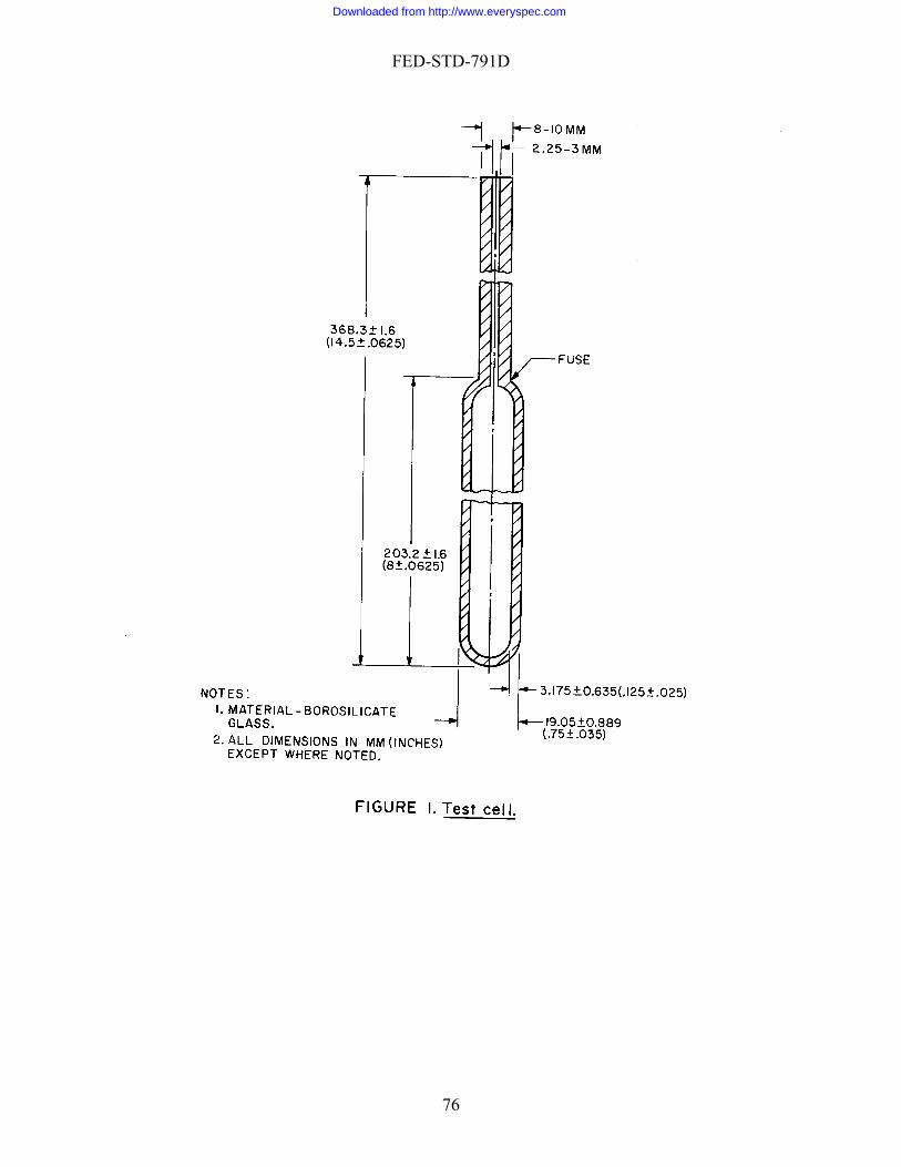
FED-STD-791D
76
Downloaded from http://www.everyspec.com
FED-STD-791D
Method 3005.4 September 30, 1986
DIRT CONTENT OF GREASE 1. SCOPE
1.1 This method is used for determining the size and concentration of foreign particles in lubricating greases. 2. SUMMARY
2.1 The test consists of applying a known quantity of grease to a microscope slide, and examining the slide with a microscope to determine the size and number of particles present. 3. SAMPLE SIZE
3.1 Approximately l mL of grease to be tested. 4. REFERENCES, STANDARDS, AND APPARATUS
4.1 Microscope, mechanical stage, 60 diameter magnification, with eyepiece micrometer (not filar) calibrated against suitability ruled, stage micrometer.
4.2 Slide, microscope, approximately 2.5 � 5.0 cm with cover glass. 4.3 Template (Fig. 1), steel (shim stock), 0.01 cm thick, approximately 2.5 � 5.0 cm,
slotted from one end for a distance of approximately 2.0 cm with a slot width of approximately 1.0 mm. The template thickness and slot width are accurately measured so that the end area of the slot can be calculated. (A hemacytometer may be used in place of the template). See Note 1.
NOTE 1:
Calculation of test results will be simplified if the template is ground to such thickness, or the slot width is adjusted so that the end area of the slot is 0.01 cm2.
4.4 Vacuum chamber, 1.0 cm of mercury (absolute), or lower (to accommodate
microscope slide). 4.5 Spatulas (2)
. MATERIALS
5.1 CAUTION - SOME MATERIALS ARE TOXIC AND HAZARDOUS. The aterials references and standards listed in this section must be handled carefully. Federal Test ethod 10000, Material Handling Safety Precautions, is a reference which lists all toxic and
azardous materials cited in FTMS 791. The synonyms, life hazard, flammability, handling and
5
mMh
77
Downloaded from http://www.everyspec.com
FED-STD-791D
storage precautions, emergency treatment and measures, and spill practices of each chemical are
. PROCEDURE
6.1 Compute the cross sectional area of the end of the slot (see 7.1).
6.2 Clean template, microscope slide and cover glass, and spatulas.
e sample for examination as follows:
resh container of grease to be tested, and with a clean spatula, scrape off and discard the surface layer.
b e
filled and the surface of the grease is level with, or slightly above the sides of the slot. the side of the slot firmly against the slide.
c. Place the slide and template in the vacuum chamber for 10 to 15 min to remove bubbles 2).
explained.
6
6.3 Prepare th
a. Open a f
. Hold the template by the unslotted end, and place it against the clean microscope slide.Using another clean spatula fill the slot with the test grease. Make sure the corners ar
Then press
or voids from the grease in the slot. (See Note
NOTE 2: Vacuum exposure may be omitted if the grease is free from entrained air.
dl to the microscope slide.
t the illumination
so that light passes straight up through the grease in the slot, as well as straight across the surface of the g
a. Adjust the stage and micrometer eyepiece so that the micrometer scale coincides with
slot. b. Move the stage slowly, so that the slot passes across the field of view. Count each
along the largest dimension of the particle.
c Record the count in three columns headed: "25 to 75 µm", "75 to 125 µm", and "over
d When the micrometer scale has reached the opposite side of the slot, move the stage axis of the slot for a distance equal to the length of the scale. (Use a minor
irregularity on the wall of the slot, or a specific particle in the grease, as a point of
. Slide the clean cover glass onto the template to shear off surplus grease. Then press the
cover glass firmly against the template until it is paralle
6.4 Mount the assembled slide on the stage of the microscope. Adjus
rease.
6.5 Determine the size and number of opaque particles.
one side of the slot, and so that one end of the scale coincides with one corner of the
opaque inclusion having a size of 25 µm or more. Particle size is determined bymeasuring
. 125 µm".
. along the
reference.) Scan this section completely across the slot. e. Continue scanning successive sections in the slot until approximately three-quarters of
the area (1 � 1.5 cm) of the slot has been inspected.
78
Downloaded from http://www.everyspec.com

FED-STD-791D
f. Record the number of sections scanned, and the total number of particles according to size.
S
T =
W
7 r of grease, using the following formu
5 µm or larger:
75 µm
Over
where: A = toB = toC = totalN = numS = leT = en
7 CALCULATION
7.1 Calculation of slot cross sectional area.
W-D=T
where: end area of template slot.
D = depth or thickness of template (cm). = width of slot (cm).
.2 Compute the number of particles per cubic centimetelas:
2
TSN C) + B+ (A
or larger:
TSNC) + (B
125µm:
TSNC
tal number of particles 25 to 75 μm. tal number of particles 75 to 125 μm.
number of particles 125 μm or larger. ber of sections of grease scanned.
ngth of micrometer scale, cm. d area of template slot, sq cm.
79
Downloaded from http://www.everyspec.com

FED-STD-791D
NOTE 3: If dirt in excess of specification limits is not found in the first run, the grease meet tshall he requirements of the test.
of the specification limits is found in first run, two more runs shall be onducted. If dirt in excess of specification limits is found in one or both of these runs, the
grease 8. REPORTING
8.1 Report the number of particles in the following ranges:
-75 µm
. PRECISION
Precision data have not been developed for this method.
Method Prepared By:
Navy - NADC - 1986
If dirt in excess
cshall fail the test.
25 75-125 µm 125 or larger µm
9
9.1
80
Downloaded from http://www.everyspec.com
FED-STD-791D
Method 3007.2 September 30, 1986
ethod is used to determine the water displacing ability of corrosion preventive ils and their stability in the presence of water.
. SUMMARY
els are immersed in distilled water and then either the test oil or a water
emulsion of the test oil. After exposure in a static humidity chamber the panels are examined r the presence of rust.
. SAMPLE SIZE
3.l Approximately 60 mL of the test oil.
. REFERENCES, STANDARDS, AND APPARATUS
4.l Standards 4.1.1 ASTM D 1748, Rust Protection by Metal Preservative In The Humidity Cabinet. 4.2 Static humidity chamber (a desiccator containing some distilled water). 4.3 Oven, forced draft, 54° 1°C (130° 2°F).
at des nt.
handling panels during processing).
4.7 Beakers, tall-form, 500 mL. 4.8 Petri dishes, 10 cm in diameter and 2 cm in height. 4.9 Controlled atmosphere (to provide 25° 3°C [77° 5°F]) and a maximum of 50
percent relative humidity. 4.10 Shaded fluorescent light. (A 15W balance illuminator type that will permit the
panel to be viewed from all angles at a distance of 3 in).
WATER DISPLACEMENT AND WATER STABILITY
1. SCOPE
1.1 This mo
2
2.1 Steel test pan
fo 3
4
4.4 Desiccator, containing an indic ing icca 4.5 Panel hook, stainless steel (for 4.6 Erlenmeyer flasks, 125 mL.
81
Downloaded from http://www.everyspec.com
FED-STD-791D
5. MATERIALS
5.l CAUTION: SOME MATERIALS ARE TOXIC AND HAZARDOUS. The hemical materials est Method 10000, aterial Handling Safety Precautions, is a reference which lists all toxic and hazardous
ed in FTMS 791. The synonyms, life hazard, flammability, handling and storage recautions, emergency treatment and measures, and spill practices of each chemical are
explain
5.2 Test panels, FS 1009 steel, 5.1 � 7.6 � 0.16 cm ( 2 � 3 � l/16 in), fabricated from ed" type low carbon, No. 4 soft temper cold rolled sheet or strip conforming to
Q-S-698. Cold drawn bar stock is not satisfactory.
5.4 Methyl alcohol (O-M-232) [1,3,0].
5.5 Distilled water.
5.6 Silica sand, white dry, sharp. The size shall be such that it meets the following sieve
a ass through a No. 10 sieve. b Minimum of 90% must pass through a No. 20 sieve. c
a -mL Erlenmeyer
flask. b tore overnight in an oven a 54° 1°C (130° 2°F). c Remove from oven and cool at 25° 3°C (77° 5°F) for testing. d prior to placing in the petri dish.
6. PRO
a Round the edges and ream out the suspension holes in accordance with ASTM D 1748. b
c. Rinse in a beaker of hot methyl alcohol.
c listed in this section must be handled carefully. Federal TMmaterials citp
ed.
open hearth "killQ
5.3 Naphtha, aliphatic (TT-N-95) [1,4,0].
requirements ASTM E11:
. 100% must p
.
. Maximum of 10% permitted to pass through a No. 50 sieve.
5.7 Surgical gauze. 5.8 Absorbent tissue. 5.9 Emulsion, water and oil prepared as follows:
. Place 50 mL of the test sample and 5 mL of distilled water in a 125
. Shake mixture thoroughly and s
.
. Shake the mixture immediately
CEDURE
6.1 Clean the steel panels as follows:
. . Wipe the surfaces with solvent soaked rags and scrub with surgical gauze swabs in a
beaker of hot naphtha.
82
Downloaded from http://www.everyspec.com

FED-STD-791D
d. Cool the panels in a desiccator until further processing. e. Test panels must be handled with a panel hook at all times, avoiding contact with any
a Sandblast the edges and lightly sandblast the back of the panels with silica sand. b
panels in a beaker of anhydrous methyl alcohol.
d nt will evaporate from the panels immediately upon withdrawal from the solvent.
e the panels in a rack at 20° from the vertical and spraying downward with naphtha.
f. e, then the back of the panel and the test surface again. g Rinse the panels in hot naphtha and hot methyl alcohol and store in a desiccator until
ed the same day as prepared.
type of contaminated surface. f. Maintain the solvents at a temperature high enough to keep the temperature of the
panels above the dew point during the cleaning operation.
6.2 Sandblast the panels as follows:
.
. Sandblast the unnumbered side, or test surface, of the panels to a fresh, uniformly abraded surface.
c. Immediately after sandblasting, place the
. Heat the methyl alcohol so that the solve
. Remove remaining residue by holding
Spray the test surfac.
cool. h. Panels are to be us
NOTE 1: Caution. Methyl alcohol and naphtha are both toxic and flammable. Do not
or breathe their fumes. Use only these materials.
are processed with the original oil as follows:
a istilled water, momentarily, and drain in a vertical position for not more than 5 s, with the bottom edge in contact with absorbent tissue.
b tion, for 15 s in a petri dish containing 50 mL of the test sample maintained at 25° 3°C (7.70° 5°F) and 50%
c. the panels momentarily and place in the static humidity chamber for 1 h at 25°
panels and rinse in
permit them to come in contact with the skinin a well ventilated area. Keep all flames away from
6.3 Three test panels
. Dip the panels into d
. Immerse the panels horizontally, and without agita
maximum relative humidity. Drain 3°C (77° 5°F).
d. At the completion of the static humidity exposure, remove themethanol.
83
Downloaded from http://www.everyspec.com

FED-STD-791D
e. Examine the test surfaces for the presence of rust, mottling, or other abnormal surface
uation.
6 lsion in accordance with the rocedure outlined in paragraph 6.3 and similarly examined.
. CALCULATIONS
8. RE
9. PR
Method Prepared By:
stains. The outer 0.32 cm (1/8 in) edge of the panels and 0.32 cm (1/8 in) around the holes is excluded from the eval
.4 Three test panels are processed with the oil-water emup
7
7.1 This section is not applicable to the test procedure.
PORTING
8.l Follow the specification requirements.
ECISION
9.1 Precision data have not been developed for this method.
Army - AR – 1986
84
Downloaded from http://www.everyspec.com
FED-STD-791D
SOLID-PARTICLE CONTAMINATION IN HYDRAULIC FLUIDS
d is used for determining the amount of solid particle contamination in ydraulic fluids.
. SUMMARY
2.2 The method consists of determining the length of time required to filter the hydraulic fluid th examining the filter under a microscope to
etermine the number and sizes of solid particles.
. SAMPLE SIZE
3.1 Approximately 100 mL of hydraulic fluid to be tested.
4. REFERENCES, STANDARDS, AND APPARATUS
4.1 Microscope, mechanical stage, 100X and 45X magnificationseyepiece calibrated (for both magnifications) against a suitably ruled, stage micrometer.
4.2 Filter holder, Pyrex (Millipore Corporation, Bedford, Mass. 01730, No.
XX10-047-00; also Gelman Instrument Co., 600 S. Wagner Road, Ann Arbor, MI, No. 1200WP).
a. Fritted-glass base and rubber stopper (No. XX10-047-02). b. Holding clamp, spring action (No. XX10-047-03). c. Funnel, graduated, 250 mL (No. XX10-047-04).
4.3 Cover, plastic (for graduated funnel) equipped with membrane filter to minimize
contamination of test filter by air.
4.4 Flask, filter, side-tube (to accommodate filter holder, par. 4.2.2), 1000 mL. 4.5 Vacuum source, 36 to 43 cm (14 to 17 in) of mercury. 4.6 Slides (4), glass 5.0 � 7.5 cm (2 � 3 in). 4.7 Bottles (3), sample, with ground-glass stoppers, 1000 mL. 4.8 Forceps, stainless-steel, plastic tipped.
4.9 Petri dish, with cover (for four 5.0 � 7.5 cm glass slides).
Method 3009.3 September 30, 1986
1. SCOPE
1.1 This methoh
2
rough a single membrane filter, and thend 3
, with micrometer
85
Downloaded from http://www.everyspec.com

FED-STD-791D
4.10 Tongs, stainless-steel. 5. MATERIALS
5.1 CAUTION - SOME MATERIALS ARE TOXIC AND HAZARDOUS. The terials listed in this section must be handled carefully. Federal Test Method 10000,
aterial Handling Safety Precautions, is a reference which lists all toxic and hazardous materials cited in
ent and measures, and spill practices of each chemical are explained.
led water.
t, water-soluble, commercial.
0,2] saturated with potassium
r sodium dichromate [1,0,1], technical grade).
5.7 Tape, transparent, pressure-sensitive.
.308-cm grid, capable of filtering 200 mL of distilled water per square cm per minute at 69 kPa (10 psi) differen
6. PR
funnel cover, and three sample bottles nd stoppers as follows:
r and detergent.
6.2 Prepare filter solvents as follows:
chemical maM
FTMS 791. The synonyms, life hazard, flammability, handling and storage precautions, emergency treatm
5.2 Distil
5.3 Alcohol, isopropyl (TT-I-735) [1,3,0]. 5.4 Petroleum ether (O-E-751) [1,4,0].
5.5 Detergen
5.6 Cleaning solution, glass (concentrated sulfuric acid [3,o
5.8 Filters, cellulose membrane, 0.45 0.02 µm pores, 4.7-cm diameter, white, 0
tial pressure and at 25°C. (Available from Millipore Corp., Gelman Instrument Co., or Decontamination, Inc.)
OCEDURE
6.1 Clean the filter flask, filter holder, graduated a
6.1.1 Wash in hot tap wate
6.1.2 Rinse with tap water. 6.1.3 Soak in hot glass-cleaning solution until clean. 6.1.4 Rinse with tap water. 6.1.5 Rinse with distilled water.
86
Downloaded from http://www.everyspec.com

FED-STD-791D
6.2.1 Insert a new membrane filter into the filter holder, and filter three 100-mL portions f distilled water to rinse the filter flask. Discard the rinsings.
6.2.2 Continue filtering enough distilled water to rinse each of the three prepared sample bottles
100-mL portions and to subsequently fill one with filtered alcohol; stopper them immediately.
.2.4 Using a new filter, filter enough petroleum ether to rinse (with three 100-mL portion e; stopper immediately.
filter flask, and discard the used filter.
glass slides as follows:
.3.2 Rinse with filtered, distilled water.
CAUTION:
o
(see 6.1 through 6.1.5) and stoppers with three 100-mL portions, and to fill one of them with filtered distilled water; stopper them immediately.
6.2.3 Replace the used filter with a new one, and using the cleaned filter flask, filter
enough isopropyl alcohol to rinse the two clean sample bottles and stoppers with three
6s) and subsequently fill the last sample bottl 6.2.5 Remove the filter holder from the 6.3 Using tongs to handle them, prepare two 6.3.1 Soak in hot glass-cleaning solution until clean. 6
Immediately re-stopper the sample bottles after each use to avoid contamination.
filtered petroleum ether and allow to air dry.
OTE 1:
6.3.3 Rinse with filtered isopropyl alcohol. 6.3.4 Rinse with
N Caution. Isopropyl alcohol and petroleum ether are flammable. Use only in a ventilated area. Keep all flames away from these materials.
red petri dish.
or the filtration of the sample as described in 6.4.1 through 6.4.3.
6.4.1 Rinse the filter holder and the funnel cover, first with filtered distilled water, then ith filtered petroleum ether.
to grip the edge, rinse a new membrane filter with filtered
petroleum ether, and install it (grid side up) on the fritted glass surface of the filter holder. Also, install a ed funnel.
the filter holder. Ground the clamp (to prevent buildup of static electricity while filtering).
well
6.3.5 When dry, immediately hinge the two slides together, using transparent tape, and store them in a clean cove
6.4 Using tongs, prepare the filter holder f
with filtered, distilled isopropyl alcohol, and finally w
6.4.2 Using clean forceps
filter in the cover for the graduat 6.4.3 Install and clamp the funnel to
87
Downloaded from http://www.everyspec.com

FED-STD-791D
6.5 Filter the sample as follows: 6.5.1 Measure 100 mL of the sample into the funnel and cover the funnel.
.
tus. Disconnect the suction source and stop timer when the fluid level is 0.5 cm above the filter membrane, then add the rins
NOT
6.5.2 If filtration time only is being determined, proceed to 6.5.2.1 and stop. If particle
count is to be measured, proceed to 6.5.2.2 and continue 6.5.2.1 Within one minute after pouring the sample into the funnel, apply suction of 36
to 43 cm (14 to 17 in) of mercury to the filtration apparatus and start the timer. When the first dry spot appears on the membrane filter, stop the timer, and disconnect the suction source.
6.5.2.2 Within one minute after pouring the sample into the funnel, start timer and apply
suction of 36 to 43 cm (14 to 17 in) of mercury to the filtration appara
e from 6.5.3 before the last of the hydraulic fluid has passed through the filter.
E 2: If the time of filtration is more than 8% of the filtration time requirement, repeat the test using the filtration procedure in 6.5.2.1.
.5.3 Wash the graduated cylinder with 50 mL of filtered petroleum ether. Remove the
cover f e funnel, replace the cover, and apply suction. Perform nnecting the suction source between washings.
6.5.4 Allow suction to continue until the filter is dry.
.6 Prepare the test filter for microscopic counting as follows:
6.6.1 Using clean forceps, remove the filter from the filter holder, and sandwich it be l
6.6.2 Using transparent tape, seal the remaining unsealed edges of the slides.
sis, using a fresh test filter and substituting filtered petroleum ether for the sample, as specified in 6.4, 6.5, and 6.6.
on on the filter paper is uniform. If the distribution is not uniform, discard the filter and repeat the test.
listing
e numbers of particles by sizes according to the six size ranges given in Table I.
6rom the funnel, pour the washings into th this washing operation once again, disco
6
tween the c eaned glass slides (see 6.3).
6.7 Prepare a blank for analy
6.8 Place the slide under the microscope (45X), and scan the entire filter to ascertain that the particle distributi
6.9 Estimate the number of particles present in the filter grid area (100 squares),th
88
Downloaded from http://www.everyspec.com

FED-STD-791D
TABLE I. Size ranges and counting magnifications. Partic
ers le size range (largest dimension), µm Counting magnifications, diamet
5 to 15 15 to
50 to 100 Over 1
100
100 100
25 25 to 50
100
00 1 (length-wide ratio under 10:1) Over 100 1 (length-wide ratio over 10:1)
45 45
1 Fibers.
mine area nd factor as follows:
6.10.1 ections (chosen at random), each f which is one grid length long (0.308 cm), and narrow enough to contain no more than 50
particle
determ or the widths. Compute the calibration factor (see 7.1).
.11 For each size range, count the particles within the sampling area, using the counting magnif y those particles lying on the upper and left boundary lines of the area as well as those within the areas selected. (Particles on the l
TABLE II. Calibration factors
6.10 For each size range, determine sampling area and calibration factor on the basis of the estimate. If the estimated number of particles of that size was 5000 or less, use sampling area and factor shown in Table II. If the estimated number was more than 5000, detera
Select a sampling area consisting of at least 10 s
os (of that size range under consideration). (See Figure 1.) 6.10.2 Using the micrometer eyepiece, measure the width of each unit area, andine the sum 6ication specified in Table I. (See Figure 2). Include in the tall
ower and right boundary lines are tallied with those in the square below or to the right.)
Estimpartic
ated number of Sampling area
Calibration factor
les 1 to 50
100 squares (total area)
51 to 1000 1001 to 5000 More than 5000
20 squares (at random) 10 squares (at random)
1 5 10
10 sections 1 1 See paragraph 6.10.
7. CALCULATIONS
7.1 Compute calibration factor:
89
Downloaded from http://www.everyspec.com

FED-STD-791D
A317 = 960 =
A 3.08ctorfa nCalibratio
. 8
or each size range, multiply the results by the calibration factor (see 6.10), subtract e values obtained for each size range for the blank from those obtained on the specimen filter
and rep
Army - ME - 1986
where: A = sum of widths of unit areas, cm
. REPORTING
8.1 Fth
ort the results as the total number of particles (of the size range) present (see Figure 2). Also, report the total filtration time and subparagraph from which it was obtained. 9. PRECISION
9.1 Precision data have not been developed for this method.
Method Prepared By:
90
Downloaded from http://www.everyspec.com

FED-STD-791D
Method 3010.1 September 30, 1986
SOLID PARTICLE CONTAMINATION IN AIRCRAFT TURBINE ENGINE LUBRICANTS (GRAVIMETRIC PROCEDURE)
. SCOPE
1.1 This method describes a gravimetric procedure for the determination of solid particle
2.1 A known volume of fluid is filtered through a pre-weighed membrane filter. The r weight is determined after washing and drying and reported as total
ontaminant. The test filter is ashed and the inorganic material remaining is reported as ash. . SAMPLE SIZE
3.1 Approximately 1 L (1 qt) of turbine engine lubricant. 3.2 The sample must be thoroughly representative of the material to be tested. This
requires vigorous agitation of the fluid before sampling. The importance of stoo strongly emphasized. All suspected sediment must be homogeneously suspended in the oil. When packaged liter (quart) samples are available the entire liter (quart) should be used.
4. REFERENCES, STANDARDS, AND APPARATUS
4.1 Membrane filters, white, plain, 4.7-cm diameter, pore sizes 1.2 and 0.22 µm.
4.2 Filter holder, 4.7 cm. 4.3 Analytical balance, sensitivity 0.1 mg. 4.4 Petri dishes, 5.0 cm in diameter. 4.5 Oven, non-circulatory air, capable of maintaining a temperature of 90°C (200°F) 4.6 Forceps, flat-bladed with unserrated tips. 4.7 Vacuum system. Muffle furnace capable of maintaining a temperature of 810°C (1500°F). 4.9 Crucibles,
30-mL capacity, squat form.
1
contamination in packaged aircraft turbine lubricants and related fluids. 2. SUMMARY
increase in filtec
3
ampling cannot be
91
Downloaded from http://www.everyspec.com

FED-STD-791D
4.10 Desiccator, with desiccant. 5. MATERIALS
5.1 CAUT ARDOUS. The materials ref ederal Test Method 10000, Material Handling Safety Precautions, is a reference which lists all toxic and
aterials cited in FTMS 791. The synonyms, life hazard, flammability, handling and orage precautions, emergency treatment and measures, and spill practices of each chemical are
explain
5.2 Isopropyl alcohol, reagent grade [1,3,0].
5.3 Petroleum ether, reagent grade, boiling point range 30° to 60°C [1,4,0].
6.1 Preparation of apparatus and containers.
6.1.1 All components of the filtration apparatus and containers must be washed with hot tap wat
.1.4 Rinse with filtered isopropyl alcohol.
6.1.5 Rinse with filtered petroleum ether.
6.1.6 Place clean plastic film or clean aluminum foil over containers and filtration apparat
NOT
ION - SOME MATERIALS ARE TOXIC AND HAZerences and standards listed in this section must be handled carefully. F
hazardous mst
ed.
6. PROCEDURE
er containing detergents. 6.1.2 Rinse with hot tap water. 6.1.3 Rinse with distilled water. 6
us. E 1: Rinse a sufficient number of times to completely remove the previous solvent.
filter. Discard the first 50 mL of each and filter enough solvents to complete testing of samples to be f must be cleaned initially as described in Section 6.1.
NOT
6.2 Preparation of reagents. 6.2.1 Filter the petroleum ether, and isopropyl alcohol, through a 0.22-µm membrane
iltered. Containers used for filtered reagents
E 2: Ground the filter mechanism when filtering flammable solvents to prevent buildup of static electricity.
92
Downloaded from http://www.everyspec.com

FED-STD-791D
6.3 All equipment used for handling samples must be cleaned as described in Section .1. Precaution must be taken to minimize apparatus contamination from all sources including
1 Identify each filter by marking the rim with a ballpoint pen, or by marking the petri ishes that will contain them. Place each filter separately in petri dish and dry it for 1/2 h in an
oven re e then placed in a desiccator and moved to the balance room in the vicinity of a balance on which weighings are to be made. Allow 1 h for the clo e. Use
rceps to place the test membrane on the balance pan by handling the edge only.
6.4.2 An air ionizer must be kept permanently on the base of the balance adjacent to the pan to charge effects. Make all weighings to the nearest 0.1 mg.
and contamination determination.
e of sample container in the region to be opened by washing with detergent and water and rinsing with tap water and filtered isopropyl alcohol. Shake the 1 L (1 qt) sample of lubricant for 15 min. Cautiously open can so as to prevent the introdu ion of metal chips into the sample.
.5.2 To keep airborne contaminants on the membrane surface to a minimum, pour some of the s vacuum. Filter the entire contents of the 1 L (1 qt) sample and thoroughly wash down the inside of the sample can with filtered petroleum ether, p
.5.3 Wash down the inside of the filter funnel. This will complete the transfer of the co el.
ash the periphery of the membrane by directing a gentle stream of petroleum ether from the edge to re not to wash any contaminant from the surface of the membrane.
ontaminant from the surface of the membrane.
NOTE 3:
6airborne particles.
6.3.1 Duplicate tests should be performed whenever more than 1 L (1 qt) of lubricant from the same lot or batch is available.
6.4 Preparation of test filters. 6.4.
dgulated to 90°C (194°F). The petri dishes ar
sed desiccator and contents to come to equilibrium with ambient temperaturfo
eliminate weighing errors due to electrostatic
6.5 Laboratory filtration 6.5.1 Thoroughly clean outsid
ct 6ample into the filter funnel before applying
assing the washings through the filter. 6
ntaminant to the filter membrane. With the vacuum applied, carefully remove the funnW
ward the center, taking ca
6.5.4 Carefully remove the test membrane from the filter base, using clean flat forceps,
and place it in a covered petri dish. Dry and reweigh as described in Section 6.4, taking care not to wash any c
l membranes may be used as described in ASTM D
2276 (Particulate Contaminant in Aviation Turbine Fuels).
For greater accuracy, contro
93
Downloaded from http://www.everyspec.com

FED-STD-791D
6.6 Determination of non-combustible contamination or ash. 6.6.1 Clean crucibles with hot detergent, wash and rinse with tap and distilled waters and
dry. Place crucibles in a muffle furnace maintained at 810°C (1500°F) for 1/2 h. Remove and place c
vicinity of the balance for 2 h. Handle crucibles with clean tongs. Weigh crucibles to the nearest 0.1 mg. Repeat this procedure until constant weight is obtai
). Hold at this temperature for 1/2 hour. Remove and place crucibles in a desiccator. Allow closed desiccator and con
onstant weight is obtained. Increase in weight is inorganic material or ash.
NOT
rucibles in a desiccator. Allow closed desiccator and contents to cool and come to equilibrium with the atmosphere in the
ned. 6.6.2 Handling the membrane filter only with clean forceps, lay it, contaminant side
upwards, in the center of the crucible. Wet it with filtered isopropyl alcohol and push it gently into the crucible.
6.6.3 Cover the crucible containing the filter membrane with a porcelain lid and place it
in a cold muffle furnace. Start the furnace and allow to come to 810°C (1500°F
tents to cool and come to equilibrium with the atmosphere in the vicinity of the balance for 2 h. Handle crucibles with clean tongs. Weigh crucibles to the nearest 0.1 mg. Repeat this procedure until c
E 4: An alternate method is to place the crucible in a triangle and put a porcelain cover over it. Place a small flame under the crucible to one side. When dry, char the
7. CALCULATIONS
nal weight of the crucible and noncombustible material, ash, mg.
mbrane.
filter membrane, being careful not to ignite. Increase the burner flame until all organic matter is distilled from the filter. Place the crucible in a preheated muffle furnace 810°C (1500°F) for 1/2 h. Weigh as in 6.6.3.
C B- A = oil of Lper mg t,Contaminan
where: A = final weight of the membrane filter with the material collected in filtration, mg. B = initial weight of the test membrane, mg. C = volume of sample in L filtered through the test membrane.
C B- D = oil of Lper mg Ash,
where:
= fiDB = initial weight of the crucible, mg. C = volume of sample in L filtered through the test me
94
Downloaded from http://www.everyspec.com
FED-STD-791D
8. R
.1 Precision data have not been developed for this method.
Method prepared by
EPORTING
8.1 Contamination, mg per L of oil. 8.2 Ash, mg per L of oil.
9. PRECISION
9
Navy - NAPC - 1986
95
Downloaded from http://www.everyspec.com
FED-STD-791D
Method 3012 September 7, 2007
DETE ULATE MATTER IN AEROSPACE HYDRAULIC FLUIDS
. SCOPE .1 This method describes the determination of particulate matter in aerospace hydraulic
fluids with an automatic particle counter analyzer working on the light interrupt principle. This document when cited in product specifications becomesrequirement.
. SUMMARY
cle inim of e c els, ct a li sensor su o unting particles in
r w bu n p re/ um o sur p to psi. e p le c ter 0 /m and mi um ple um
it of 10,000 particles/mL
is mL
S
um fiv han , fitted with photoelectric ab r counting particles in th 00 range size,
d an automatic bottle sampler with a built-in pressure/vacuum chamber that can subject
.2 Sample bottles - Round flat-bottomed glass bottles fitted with a polypropylene threaded cap forming a seal with the bottle without the use of any insert, approximately 250 mL capacity or manufacturer’s recommended size.
.3 Solvent dispenser – Suitable dispensers fitted with a ≤0.45 µm membrane filter (Millipore HAWP 047 or equivalent) at the outlet. If solvent has been pre-filtered using a 0.45 µm or smaller size filter, then an inline filter is not required.
4.4 Timer - Timer that is accurate to the second, ±0.5.
RMINATION OF PARTIC
1
1
a mandatory test
2 2.1 This method utilizes an automatic parti counter with a m um fiv hann
fitted with photoelectric level dete ors, quid itable f r cothe 2-400 µm range size, and an automatic bottle sample ith a ilt-i ressu vacuchamber that can subject samples t pres es u 60 Th artic oun must be able to deliver flow rates of 10 to 2 0 mL in, h le a nim sam vol e of 100 mL and have a minimum concentration lim .
3. SAMPLE SIZES 3.1 Minimum sample size for analysis 120 (4 oz). 4. STANDARDS AND APPARATU 4.1 Automatic particle counter with a minim of e c nels
level detectors, a liquid sensor suit le fo e 2-4 µmansamples to pressures up to 60 psi.
4
4
96
Downloaded from http://www.everyspec.com

FED-STD-791D
5. MATERIALS 5.1 Solvent – Hexanes (certified) filtered through a ≤ 0.45 µm (Millipore HAWP 047 or
equivalent) filter prior to use.
5.2 Detergent – Micro-90 Cleaning solution (available through Fisher Scientific and Cole-Parmer) or equivalent.
6.1 .1.1 Particle counters will be calibrated every 6 months, and after any repairs that could affect
calibration or whenever there is a reason to suspect inaccuracy in test results.
.1.2 Instrument calibration will be performed using a certified calibration kit consisting of a
6.2 .2.1 Wash sample bottle thoroughly with warm tap water containing detergent.
ater.
.2.4 Oven dry at 90 ± 5°C.
.2.5 Allow to cool at room temperature in a suitable contamination-free environment.
6.2.6 6.2.7
.3 SAMPLE PREPARATION
6.3.1 .3.1.1 Fluid samples shall be rejected if visibly contaminated with water or excessive solids.
6. PROCEDURE
CALIBRATION
6
6
known suspension of Arizona Certified Fine Test Dust (ACFTD) in MIL-PRF-5606 (NATO Code H-515) hydraulic fluid by qualified personnel and adhering to the manufacturer’s operations manual.
SAMPLER BOTTLE PREPARATION
6 6.2.2 Rinse with warm tap w 6.2.3 Rinse with either distilled or deionized water. 6 6
Rinse with filtered solvent.
Drip dry. 6.2.8 Store bottles with caps in place at room temperature, in a suitable contamination-free
environment.
6
Bottle sample.
6
97
Downloaded from http://www.everyspec.com

FED-STD-791D
6.3.1.2 Using filtered solvent, thoroughly clean the outside of the bottle, particularly in the region of the cap.
6.3.2
vent.
.3.2.2 Shake sample vigorously by hand for one minute.
.3.2.3 Puncture the cleaned surface with a cleaned and rinsed tool, making a hole that is no
6.3.3.1
ribution of particles in the fluid.
mended volume) to a sampler bottle and cap it.
.4 SET-UP PARAMETERS
.4.1 The particle counters will have the following set-up:
.4.1.1 Flow rate – 60 ± 2 mL/min (or that recommended by manufacturer).
4.1.2 Vacuum rate – a minimum of 53.5 kPa (15.8 in Hg).
.4.1.3 Sample volume – The sample shall be counted in at least two equal volumes of at least 20 consecutively.
.4.2 Ensure that the particle counter has been switched on at least 30 min prior to start of
s recommendation.
lysis, run a sample of filtered solvent to verify particle cleanliness level. The particle counter must meet SAE AS 4059 (NAS 1638) Class 00 (Table 1) limits.
Hermetically sealed containers.
6.3.2.1 Thoroughly clean the outside of the container, particularly the top where it will be
opened, with filtered sol 6 6
larger than necessary. 6.3.2.4 Transfer a mid-stream sample of at least 125 mL (or manufacturer’s recommended
volume) to a sampler bottle and cap it. 6.3.3 Other containers.
Thoroughly clean the outside with filtered hexanes paying particular attention to the cap region.
6.3.3.2 Agitate container to ensure adequate dist 6.3.3.3 Transfer a mid-section sample of at least 125 mL (or manufacturer’s recom
6 6 6 6. 6
mL each, run 6.4.1.4 Set particle counter to differential mode.
6analysis or follow manufacturer’
6.4.3 Prior to daily ana
98
Downloaded from http://www.everyspec.com

FED-STD-791D
Table 1 – SAE AS 4059 (NAS 1638) Class 00
m) Number of Particles / 100 mL (max) Particle Size Range (µ
5 - 15 125 16 - 25 22 26 - 50 4 51 - 100 1
>100 0 6.5 SAMPLE ANALYSIS 6.5.1 Shake the bottle v
within two minutesigorously by hand for one minute. Particle counting shall commence after shaking.
0 seconds to remove air bubbles.
ted channel.
.1 number of particles per 100 mL in
26 to 50 µm 51 to 100 µm
6.5.2 Place sampler bottle in sample assembly and apply a vacuum of at least 53.5 kPa (15.8 in
Hg) for 4 .5.3 Turn-off vacuum source and immediately start particle count. 6
6.5.4 Flush the sensor with a small volume of sample. 6.5.5 Record count result per calibra 6.5.6 Repeat sample counting as appropriate. 6.5.7 After each sample run, flush the sensor with filtered solvent. 7. CALCULATIONS 7.1 Average the particle count of the runs (discarding any statistically suspect data) per
volume used per channel. 8 REPORTING
Report to no more than three significant figures, the8the following size ranges: (DELTA mode). 5 to 15 µm 16 to 25 µm
99
Downloaded from http://www.everyspec.com

FED-STD-791D
>100 µm
9. PRECISION 9.1 Precision data have no ethod
Method Prepared By:
AFTL - 2007
t been developed for this m .
100
Downloaded from http://www.everyspec.com
FED-STD-791D
Method 3013 September 30, 1986
PARTICULATE CONTAMINATION IN SYNTHETIC TURBINE ENGINE LUBRICANTS
. SCOPE
1.1 This method describes a gravimetric procedure for the determination of particulate contamination in synthetic turbine engine lubricating oils. 2. SUMMARY
2.1 A known volume of oil is filtered through a pre-weighed membrane filter. Theincrease in filter weight is determined after washing and drying and is considered particulatecontaminant. Particulate contaminant per liter of oil is calculated from the volume of oil filteredand the weight of particulate contaminant. 3. SAMPLE
3.1 Approximately 1 L of the oil to be tested. 4. REFERENCES, STANDARDS, AND APPARATUS
4.1 Membrane filters, 4.7 cm diameter, absolute pore size of 3 µm and 0.45 µm. Filters must be compatible with the required reagents and with MIL-PRF-7808 lubricants at elevated temperatures. Millipore MF filters or equivalent shall be used.
4.2 Filter holder, 4.7 cm diameter. 4.3 Analytical balance, sensitivity 0.1 mg. 4.4 Petri dishes, 10.0 cm diameter with covers. 4.5 Oven, non-circulatory air, capable of maintaining temperature of 90°C. 4.6 Forceps, flat-bladed without serrated tips. 4.7 Vacuum system, 62.5 cm Hg or better. 4.8 Laboratory wash bottle.
DETERMINATION OF
1
101
Downloaded from http://www.everyspec.com

FED-STD-791D
5. MATERIALS
5.1 CAUTION - SOME MATERIALS ARE TOXIC AND HAZARDOUS. The ch , Material Handling Safety Precautio s all toxic and hazardous materials ited in FTMS 791. The synonyms, life hazard, flammability, handling and storage precautions, mergency treatment and measures, and spill practices of each chemical are explained.
5.2 Isopropyl alcohol, reagent grade [1,3,0].
gent grade [1,4,0].
entire contents must be filtered. When samples present packaged 8-oz containers, the entire contents of at least two, but no more than four, of
ust be filtered. When the material is packaged in containers larger than 1 t, a representative 1 L (1 qt) sample must be taken in a clean container for the filtration test.
The en
when not in use.
.3 Preparation of reagents.
.3.1 Filter the isopropyl alcohol and petroleum ether through a 0.45-µm membrane filter. each solvent filtered. Filtering equipment and storage containers for the solvents must be cleaned as described in 6.2.
NOTE:
emical materials listed in this section must be handled carefully. Federal Test Method 10000ns, is a reference which list
ce
5.3 Petroleum ether, 30° to 60°C boiling range, rea
6. PROCEDURE
6.1 Sampling 6.1.1 The sample must be representative of the material to be tested. When samples
represent packaged quart containers, therethe 8-oz containers mq
tire contents of these samples must be filtered.
6.2 Preparation of apparatus and containers.
6.2.1 Wash all components of the filtering apparatus with hot water and detergent. 6.2.2 Rinse with hot tap water. 6.2.3 Rinse with distilled water. 6.2.4 Rinse with filtered isopropyl alcohol. 6.2.5 Rinse with filtered petroleum ether. 6.2.6 Place clean plastic wrap or aluminum foil over the filtering apparatus
6 6Discard the first 50 mL of
Ground the filter mechanism to prevent build-up of static electricity.
102
Downloaded from http://www.everyspec.com
FED-STD-791D
6.4 Preparation of test filters.
t. If present, wash top of container using laboratory wash bottle containing filtered petroleum ether.
6.5.2 Shake sample mechanically for 5 min prior to test. Puncture small opening in top of container (vent in case of screw cap containers) and heat to a maximum of 60°C to facilitate filtering. Lubricant formulations which filter readily (30 min or less per L [qt]) need not be heated.
sample must be filtered through one filter. Thoroughly wash down the inside of the sample container with filtered petroleum ether, passing the was
aining filtered petroleum ether. With vacuum still applied, carefully remove the funnel. Wash the periphe a gentle stream of filtered petroleum ether from the edge toward the center, taking care not to wash any contaminant from the surface of the membrane.
.5.5 Carefully remove the test membrane from the filter base and place it in a petri dish. Dry and 7. CAL
st filter and the volume of sample filtered.
6.4.1 Place a 3-µm membrane filter in a petri dish and dry for 30 min in an oven regulated to 90°C with petri dish lid ajar. Remove petri dish and with lid closed, place in vicinity of balance on which weighings are to be made. Allow filters to cool for 30 min and weigh to the nearest 0.1 mg. Use forceps to handle the test membranes. An air ionizer must be utilized during all weighings to eliminate errors due to electrostatic charge effects.
6.5 Filtering of test sample. 6.5.1 Inspect visually the top of the sample container for dust and dir
6.5.3 Cautiously open containers so as to prevent the introduction of metal particles into
the sample. Pour approximately 50 mL of sample into the assembled filtering apparatus containing the pre-weighed filter and apply vacuum. Filter entire contents of the sample container and record filtering time in min. All of the
hings through the filter. 6.5.4 Wash down the inside of the filter funnel using laboratory wash bottle cont
ry of the membrane by directing
6 reweigh as described in 6.4.1.
CULATIONS
7.1 Calculate particulate contaminant per liter of oil from the initial and final weight of the te
CB-A = test ofmg/liter t,contaminan eParticulat
where: A = final weight of test filter in mg. B = initial weight of test membrane in mg. C = volume of sample measure in liters passed through the filter.
103
Downloaded from http://www.everyspec.com
FED-STD-791D
8. REP
Method Prepared By:
/POSL - 1986
ORTING
8.1 Report the contaminant in mg/L and filtering time in min. 9. PRECISION
9.1 Precision data have not been developed for this method.
Air Force - AFWAL
104
Downloaded from http://www.everyspec.com

FED-STD-791D
Method 3110.1 September 30, 1986
IL IN CUTTING FLUIDS BY INFRARED SPECTROPHOTOMETRY
1. SCO
1.1 This method of analysis is intended for the determination of fatty oil in sulfurized fatty mineral and sulfurized, chlorinated fatty mineral cutting fluids. The massumption that the fatty oil will consist entirely of lard oil. The method is not applicable to thefatty oil analysis of cutting oils which contain oxidized oils roups which also absorb at 1743 cm-1, the point in the spectrum upon which this analysis is ased. Sulfur- and chlorine-containing compounds which often interfere with the conventional
analysis do not interfere with this metho
MARY
.1 The total concentration of fatty oil i
hotometry. A curve showing the relaticm-1 is used to determine the percent of
PLE SIZE
ately 100 mL of the oil to
RENCES, STANDARDS, AND APPA
eter capa1743 cm-1. The Perkin-Elmer Infrared ory. A sealed liquid cell with sodium c is recommended that the path length use
ERIALS
ION - SOME MATERIALl materials listed in this section must be
ited in FTMS 791. The synonyms, life hazard, flammability, handling and storage precautions, mergency treatment and measures, and spill practices of each chemical are explained.
5.2 Spectrophotometric standards of A-A-59197 Fatty Oil in 0.0-15% Mineral Oil.
FATTY O
PE
ethod is based on the
or compounds containing carbonyl gbfatty oil d. 2. SUM
2 n a cutting fluid is determined by measuring the absorbance at the carbonyl absorption band at 1743 cm-1 by means of infrared spectrop onship between fatty oil content and absorbance at 1743 fatty oil in the cutting fluid. 3. SAM
3.1 Approxim be tested. 4. REFE RATUS
4.1 An infrared spectrophotom ble of producing a distinct carbonyl absorption band at Spectrophotometer, Model 621, has been found satisfact hloride or potassium bromide windows may be used. It d be approximately 0.025 mm. 5. MAT
5.1 CAUT S ARE TOXIC AND HAZARDOUS. The chemica handled carefully. Federal Test Method 10000, Material Handling Safety Precautions, is a reference which lists all toxic and hazardous materials ce
105
Downloaded from http://www.everyspec.com
FED-STD-791D
6. PROCEDURE
6.1 Calibrate the spectrophotometer in accordance with the manufacturer's instructions. repare a series of at least five standards consisting of mixtures of fatty oil meeting the
require If the mple being analyzed contains more than 15% fatty oil, dilute it with sufficient mineral oil
the requirements of fatty oil in 0.0 – 15% mineral oil, to reduce the fatty oil content elow 15% so that the standards prepared above can be utilized. Determine the absorbance
values
e filled cell in the beam of the infrared ectrophotometer and scan between 2000 and 1500 cm-1. Determine absorbance of the band at
rmine absorbance of the band at 1743 cm-1 using the Base Line Method. This ethod consists of drawing the base line as nearly parallel as possible to the radiant energy
backgro
repared from the standards and to compensate for any variability in equipment operation. If the standards do not agree with the previously prepared plot, prepare a new
orking curve prior to analyzing the sample. . CALCULATIONS
7.1 Calculation of absorbance of 1743 cm band:
A =
. PRECISION
9.1 Use the following criteria as a basis for judging the acceptability of results (95% confidence):
Pments of A-A-59197 and mineral oil meeting the requirements of 0.0 – 15%.
sawhich meetsb
of the standards in accordance with 5.2 and plot the percent fatty oil against the absorbance values at 1743 cm-1.
6.2 Thoroughly mix the sample but avoid producing air bubbles. Fill the cavity in the
sealed cell, avoiding any air inclusion. Samples suspected of containing any moisture should not be used as the moisture will fog the sodium chloride or potassium bromide windows or change the effective path length of the cell. Place thsp1743 cm-1. Detem
und as shown in Figure 1. The absorbance is then calculated from the equation in Section 7.1. Determine the percent fatty oil in the sample from the plot prepared from the standards (see 5.2). It is suggested that standards bracketing the expected fatty oil concentration be run concurrently with the sample undergoing test to check the previously prepared plot pabsorbance of thesew
7
-1
TT = A
P
B10log
where:
absorbance TB = the distance from the zero line to the base line TP = the distance from the zero line to the selected absorption peak.
8. REPORTING
8.1 Report the percent of fatty oil found in the cutting fluid.
9
106
Downloaded from http://www.everyspec.com
FED-STD-791D
a. Repeatability. Duplicate results by the same operator should be considered suspect if they differ by more than 0.2%.
b
. Reproducibility. The results submitted by each of two laboratories should be considered suspect if they differ by more than 0.3%.
Method Prepared By:
Army - AR - 1986
107
Downloaded from http://www.everyspec.com

FED-STD-791D
September 30, 1986
SULFUR IN CUTTING FLUIDS (ACTIVE AND TOTAL)
1. SCOPE
1.1 This method is used for the determination of active and total sulfur is used in conjunction with ASTM D 129.
. SUMMARY
2.1 Total sulfur content of the fluid is determined in accordance with ASTM D 129 with e noted exceptions. Active sulfur content is determined by first reacting the fluid with some
opper powder, determining the sulfur content of the reacted fluid and then subtracting this lfur content from the total sulfur content.
. SAMPLE SIZE
3.1 Approximately 45 mL of the cutting fluid to be tested.
. REFERENCES, STANDARDS, AND APPARATUS
4.1 Standards 4.1.1 ASTM Method D 129, Sulfur in Petroleum Products by the Bomb Method. 4.2 Beaker, lipless, tall-form, 250 mL capacity. 4.3 Auger stirrer blade, 1.0 cm wide and 7.5 cm high. 4.4 Thermometer, 177°C (350°F), range of 150° to 200°C. 4.5 Bomb, minimum capacity 300 mL, electrically fired (see ASTM D 129). 4.6 Sample cup, platinum or nickel (see ASTM D 129).
. MATERIALS
5.1 CAUTION - SOME MATERIALS ARE TOXIC AND HAZARDOUS. The hemical materials listed in this section must be handled carefully. Federal Test Method 10000, aterial Handling Safety Precautions, is a reference which lists all toxic and hazardous materials
ited in FTMS 791. The synonyms, life hazard, flammability, handling and storage precautions, mergency treatment.
Method 3180.2
in cutting fluids. It 2
thcsu 3
4
5
cMce
108
Downloaded from http://www.everyspec.com
FED-STD-791D
5.2 Copper powder, ACS. Baker Chemi l ompan Cataurified Powder, has been found satisfactory.
5.4 Acetone, ACS [1,3,0].
5.5 Isooctane, knock test grade [0,3,0].
No. 42 or equivalent.
wire, iron, approximately 26 B&S gage.
. PROCEDURE
6.1 Preparation of copper powder. Place approximately 20 g of copper powder in a 250-mL d. Heat the beaker and ontents gently until the surface of the copper powder begins to react. Allow the reaction to
s free of oxides. Add sufficient istilled water to stop the reaction. Decant and discard supernatant liquid. Wash the copper
powder atman or equivalent filter paper with distilled water until the wash water shows no trace of nitric acid when tested with blue litmus paper. When all the nitric acid has been re er. If not ready to proceed with the test, the dried copper powder may be stored under knock test grade isoocta
NOT
ca C y log No. 1728, Copper, P
5.3 Nitric acid, 5% [2,0,0].
5.6 Filter paper, Whatman No. 4 and
5.7 Firing
5.8 Blue litmus paper. 5.9 Materials required for ASTM D 129.
6
beaker and add 5% nitric acid until all the powder is covereccontinue for about one minute or until the copper powder id
on a No. 4 Wh
moved, wash the copper powder with sufficient acetone to remove all traces of wat
ne.
E 1: Caution. Isooctane is flammable. Do not use isooctane near an open flame.
beaker and add approximately 2.0 ± 0.1 g of the dried copper powder prepared in 6.1. Place the beaker 3°C (300°± 5°F) while stirring t 1750 rpm for at least 1 hour. At the end of the heating and stirring period, cool the mixture to
and filter through a Whatman No. 4 or equivalent filter paper. Determine the sulfur content of the filtrate (the reacted fluid) in accordance with ASTM D 129 with the followi
6.2 Sulfur determinations. 6.2.1 Active sulfur. Place 20 ± 1 g of the sample fluid in a 250-mL tall-form lipless
and contents on a hot plate and heat the mixture to 149° ±aroom temperature
ng exceptions:
a. Paragraphs 3.2, 3.3: A nickel cup and iron wire may be used b. Paragraph 5.1: Place 15 mL of sodium carbonate solution in the bomb in place of
the prescribed 5 mL
109
Downloaded from http://www.everyspec.com
FED-STD-791D
c. Paragraph 5.5: After removing the beaker containing the barium sulfate from the hot plate, permit the barium sulfate to settle for a minimum of 4 hours, preferably overnight.
. Paragraph 5.5: After the barium sulfate has settled for a minimum of 4 hours, filter the sup atman No. 24 or equivalent filter paper and wash with hot water until all traces of barium chloride are removed. The active sulfur content of the cutting fluid is equivalent to the difference between the total sulfur content of the cutting fluid (as determ ntent of the reacted cutting fluid.
.2.2 Total sulfur. Determine the total sulfur content of the cutting fluid in accordance
with A 7. CAL
ulfur as calculated in 6.1 of ASTM D 129.
No precision data available for sulfur content of reacted fluids.
Method Prepared By:
Army - AR – 1986
lfur
dernatant liquid through a Wh
ined in 6.2.2) and the sulfur co
6STM D 129 with the exceptions listed in paragraph 6.2.1.
CULATIONS
7.1 Weight percent of s 7.2
fluid reacted of content sulfur - content sulfur Total = content suActive
8. REPORTING
8.1 Report active and total sulfur contents to the nearest 0.01%. 9. PRECISION
9.1 Reference paragraph 8.1 of ASTM D 129 for percent sulfur contents. 9.2
110
Downloaded from http://www.everyspec.com
FED-STD-791D
6
t at a specified temperature, allowing the emulsion to remain undisturbed at the test temperature for the time required by the specification, and examining the emulsion for any separation. 3. SAMPLE SIZE
3.1 Approximately 40 mL of the oil or fluid to be tested.
. REFERENCES, STANDARDS, AND APPARATUS
4.1 Graduated cylinder, 100 mL (approximately 28.6 mm [1-1/8 in] I.D.).
4.2 Heating bath (oil or water), 54° " 0.5°C (130° " 1°F) (unless otherwise specified) deep en
a. Paddle, copper strip, 12.1 H 1.9 H 0.16 cm (4-3/4 H 3/4 H 1/16 in). b. Shaft, stirring, with means for attaching paddle long enough to im
approximately 0.64 cm (1/4 in) from bottom of graduated cylinder. c. Motor, stirring, approximately 1500 rpm, for rotating shaft and padd
4.4 Thermometer (range to suit requirements of specification). 4.5 Wooden stick or rubber policeman.
5. MATERIALS
5.1 CAUTION - SOME MATERIALS ARE TOXIC AND HAZARDOUS. The
chemical materials listed in this section must be handled carefully. Federal Test Method 10000, Material Handling Safety Precautions, is a reference which lists all toxic and hazardous materials cited in FTMS 791. The synonyms, life hazard, flammability, handling and storage precautions, emergency treatment and measures, and spill practices of each chemical are explained.
Method 3201.7
September 30, 198
EMULSION (PETROLEUM AND PETROLEUM-LIKE PRODUCTS) 1. SCOPE
1.1 This method is used for determining the emulsifying tendency of petroleum and petroleum-like products. 2. SUMMARY
2.1 The test consists of stirring the sample and its emulsifying agen
4
ough to cover 85 mL mark of the graduated cylinder. 4.3 Stirring mechanism (Figure 1) consisting of:
merse paddle to
le.
111
Downloaded from http://www.everyspec.com

FED-STD-791D
5.2 Emulsifying agent (distilled wa r, so m c ride ution r syn tic s atequired by the specification.
te diu hlo sol , o the eaw r) as re
. PROCEDURE
6.1 Secure paddle to shaft and connect shaft to stirring motor.
6.2 Preheat and regulate bath to maintain test temperature.
ately 40 mL each of sample and emulsifying agent into graduated ylinder. Immerse cylinder in bath to 85 mL mark, and allow contents of cylinder to reach test
1/4
tor, raise paddle from cylinder, and remove emulsion from paddle with stick
r rubber policeman. Return as much of the emulsion as possible to cylinder.
6.6 Allow emulsion to remain undisturbed at the test temperature for the time required
7. CAL
8. REPORTING
.1 Examine emulsion for any separation, and report whether end product conforms to specif
9. PREC
9.1 Precision data have not been developed for this method.
Method Prepared By:
Army - AR - 1986
6
6.3 Pour approxim
ctemperature.
6.4 Lower paddle into cylinder so that bottom of paddle is approximately 0.64 cm (in) from bottom of cylinder. Start stirring motor and allow it to rotate paddle at approximately1500 rpm for 300 " 15 sec.
6.5 Stop moo
by the specification.
CULATIONS
7.1 This section is not applicable to the test procedure.
8ication.
ISION
112
Downloaded from http://www.everyspec.com

FED-STD-791D
113
Downloaded from http://www.everyspec.com
FED-STD-791D
Method 3205.3
6.2 Let bottle stand for 1 h at 21° to 32°C (70° to 90°F). At end of this period, examine r evidence of separation.
. CALCULATIONS
7.1 This section is not applicable to the test procedure.
September 30,1986 EMULSION (SOLUBLE CUTTING OILS) 1. SCOPE
1.1 This method is used for determining the emulsifying tendency of soluble cutting oils. 2. SUMMARY
2.1 The test consists of shaking a mixture of sample oil and water, allowing the mixture to stand, and examining for evidence of separation and for air bubbles. 3. SAMPLE SIZE
3.1 Approximately 5 mL of oil to be tested. 4. REFERENCES, STANDARDS, AND APPARATUS
4.1 Sample bottle, 120 mL (4 oz), with stopper. 5. MATERIALS
5.1 CAUTION - SOME MATERIALS ARE TOXIC AND HAZARDOUS. The chemical materials listed in this section must be handled carefully. Federal Test Method 10000, Material Handling Safety Precautions, is a reference which lists all toxic and hazardous materials cited in FTMS 791. The synonyms, life hazard, flammability, handling and storage precautions, emergency treatment and measures, and spill practices of each chemical are explained.
5.2 Distilled water.
6. PROCEDURE
6.1 Pour 95 mL of distilled water into sample bottle and add 5 mL of test oil. Shake vigorously for 1 min.
fo 7
114
Downloaded from http://www.everyspec.com
FED-STD-791D
8. REPORTING
8.1 Report the sample as acceptable if no separation is apparent and as unacceptable if paration occurs.
. PRECISION
9.1 Precision data have not been developed for this method.
Method Prepared By:
Army - AR - 1986
se 9
115
Downloaded from http://www.everyspec.com

FED-STD-791D
Method 3403.2
COMPATIBILITY OF TURBINE LUBRICATING OILS
1. SCO
1.1 This method is used for determining the compatibility of aircraft turbine lubricants ith specific referee lubricants.
2. SUMMARY
2.1 This method consists essentially of preparing mixtures of the sample lubricant and ree lubricant in three concentrations, maintais, and then centrifuging them for ten-minute stant.
AMPLE SIZE
3.1 Approximately 300 mL of the aircra
EFERENCES, STANDARDS, AND APPA
4.1 Oven, gravity-convection, 105° 1°ks).
4.2 Erlenmeyer flasks, (3), Pyrex, 250-m 4.3 Centrifuge tubes, cone-shaped, 100 m 4.4 Centrifuge, capable of spinning two o
trifugal force of 600 to 700 at the tips of the 4.5 Bath, hot water, 93° 3°C (200° 5
s to be spun).
ATERIALS
5.1 CAUTION - SOME MATERIALS Alisted in this s
thod 10000, Material Handling Safety Precauardous materials cited in FTMS 791. The sy lity, handling and
explained.
September 30, 1986
PE
w
refe ning the mixtures at a fixed temperature for 7 day intervals until the volumes of sediment becomes con 3. S
ft turbine lubricant to be tested. 4. R RATUS
C (221° 2°F) (to accommodate three 250-mL flas
L with glass stoppers.
L (see ASTM D 2273).
r more centrifuge tubes, and applying a relative cen tubes.
°F) (for simultaneous heating of centrifuge tube
5. M
RE TOXIC AND HAZARDOUS. The materials references and standards ection must be handled carefully. Federal Test Me tions, is a reference which lists all toxic and haz nonyms, life hazard, flammabistorage precautions, emergency treatment and measures, and spill practices of each chemical are
116
Downloaded from http://www.everyspec.com

FED-STD-791D
5.2 Referee lubricant (in accordance with lubricant specification), 300 mL.
5.4 Cleaning solution, glass (concentrated sulfuric acid [2,0,2] saturated with potassium
or sodium dichrom
URE
a. Thoroughly rinse with 1,1,1-trichloroethane in hood, and allow to air dry in hood.
NOTE 1:
5.3 1,1,1-Trichloroethane (ASTM D 4126).
ate [1,0,1], technical grade). 6. PROCED
6.1 Clean all flasks and centrifuge tubes as follows:
Caution. 1,1,1-Trichloroethane is toxic. Do not breathe its fumes nor allow it
inse first with tap water, then with distilled water, and dry in an oven 105°C (220°F).
three 200-mL mixtures, in 250-mL Erlenmeyer flasks, using the following roportions:
a. Sample, 180 mL; referee lubricant, 20 mL. 0 mL.
c. Sample, 20 mL; referee lubricant, 180 mL.
.3 Stopper with a cork stopper, and dentify eac flask.
t 105° 3°C (221° 5°F).
to cool to room temperature.
lly shake each e) vigorously 1 min, and immediately fill two clean centrifuge tubes to the 100 mL mark with its contents. Identify the contents of each tube.
NOTE 2:
to come in contact with the skin.
b. Immerse in glass cleaning solution for at least 2 h. c. R
6.2 Prepare
p
b. Sample, 100 mL; referee lubricant, 10
6 i h 6.4 Manually shake each flask vigorously for 1 min. 6.5 Loosen the stoppers, and heat the flasks in an oven for 168 h a
6.6 After the 168-hour period, remove the flasks, and allow them
6.7 Manua flask (one at a tim
Do not fill more pairs of tubes than can be spun by the centrifuge at one time.
e been
at the tubes for 5 min in a hot-water bath at 93° 3°C (200° 5°F).
Allow the remaining filled flasks to stand until the first set of tubes havcompletely centrifuged.
6.8 Process the centrifuge tubes as follows:
a. He
117
Downloaded from http://www.everyspec.com
FED-STD-791D
b. Mount the tubes opposite each other in the centrifuge, being careful to locate the tubes to achieve proper balance of the centrifuge.
c ed until the relative centrifugal force at the tips of the tubes is 600 to 700. Run the centrifuge for 10 min.
d
e. Repeat the 10 min centrifuging and sediment readings until the amount of sediment nstant for three consecutive readings.
7. CAL
.
8. REPORTING
8.1 Report the average volume of sediment in each pair of centrifuge tubes. 9. PR
Method prepared by:
Air Force - AFWAL/POSL - 1986
. Turn on the centrifuge, and increase the spe
. After the ten-minute period, record the amount of sediment in each tube to the nearest 0.001 mL.
remains co
CULATIONS
7.1 Compute the average sediment volume to the nearest 0.001 mL of each tube pair
ECISION
9.1 Precision data have not been developed for this method.
118
Downloaded from http://www.everyspec.com
FED-STD-791D
September 30, 1986
DATION 1. SC
1.1 This method describes procedures used to evaluate the thermal stability jet lubricants under varying levels of severity.
2. SUM
of the severity levels (type 1, 1-1/2, or 2) r a controlled number of hours. At periodic intervals during the test and at the end of test,
samplemple of new oil. A visual inspection is made at the end of test of the accumulated deposits on
earing housing. A weighted numerical rating system is used for rating dividual areas as well as for obtaining an overall rating. Additional data on relative sludge
forming r element and a 40-mesh filter element.
. SAMPLE SIZE 4. REFERENCES, STANDARDS AND APPARATUS
4.1 The apparatus used in this method is the Erdco high temperature bearing head ounted on a suitable drive test stand, similar to the Erdco universal test stand. It is not
4.1.1 Erdco high temperature bearing head. The bearing head is divided inter-nally into
two main sections. The front or test section with its separate test oil system houses the unshielded 100-mm straight roller test bearing. The temperature of the test bearing is controlled by supplying heat to the outer race of the bearing. The outer race is secured in a bearing mount assembly containing wound Calrod heating elements packed in aluminum oxide for even heat distribution. The rear or support section of the bearing head houses the externally loaded, main shaft support bearing, together with a separate oil system. The test and support sections of the modified bearing head are separated by a screw thread seal to prevent mixing of the test and support oil. Details covering the bearing head and screw thread seal assembly are shown in Figure 1.
4.1.1.1 Test oil jet. A standard No. 60 drill size jet located at 12 o'clock on a 0.13335-m
(5.250-in) diameter should be used. The size of the jet should be checked with a No. 60 drill and a visual check of axial straightness made with the drill inserted in the jet. Corrections for orifice
Method 3410.1
HIGH TEMPERATURE DEPOSIT AND OIL DEGRACHARACTERISTICS OF AVIATION TURBINE OILS
OPE
characteristics of turbo
MARY
2.1 Sample of the lubricant is subjected to onefo
s of the oil are examined for both physical and chemical changes when compared to the sathe bearing and bin
tendencies on oils are obtained by weighing a 100-mesh filte
3
mmandatory to use the "universal drive" to power the bearing. The support oil system and the test oil system are separate units and of special design for the Erdco high temperature bearing head.
119
Downloaded from http://www.everyspec.com

FED-STD-791D
size and axial straightness should be made by silver soldering the orifice end of the jet tube and redrilling.
4.1.2 T d on the free nd of the shaft in th ng is loaded dially by the slight downward displacement of the free end of the shaft caused by a straight
orce from the loading piston acting on the outer race of the main support ball bearing own in Figure 1. The test bearing is lubricated by a single jet located at 12 o'clock which
supplie nd the O.D.
t bearing mount. The bearing mount is made with an outer race removal feature
hich permits the removal of the bearing outer race for cleaning and inspection without disturb
ery
Three thermocouple junctions are silver-soldered to the outer-race housing. The ldering operation should leave enough excess metal to provide good contact with the outer race
to the mount. Each of the three thermocouple leads are routed out directly rough the bearing housing or end cover at 120° intervals.
4.1.3.2 Thermocouple packing. Teflon or an equivalent should be used for all thermo lies
oil cycle starts at the tank where three 1500-W, series connected heater elements (refer to 4.1.7) maintai
en
in
.4.1 The test oil system provides for the installation of a fine 100-mesh filter screen (stainless steel, Erdco P/N 1RB 2006 S.S. for Type 1-1/2 test conditions) in the pressure line only ju
est bearing. An unshielded 0.10-m straight roller bearing is mounte
e e test oil compartment of the bearing head. The test beariradownward fsh
s essentially a solid stream of oil midway between the I.D. of the outer race aof the retainer on the top or unloaded position of the test bearing.
4.1.3 Tesw
ing the aluminum oxide packing. Three spot-type thermocouples are located 120° apart (radially around the I.D. of the bearing mount and indicate the skin temperature on the periphof the outer race, which is pressed into contact with these thermocouple junctions when it is installed in the bearing mount. One of these three thermocouple leads is connected to a differentiating type temperature controller (proportional controller) or to a suitable autotransformer. "ON-OFF" type control is not recommended.
4.1.3.1
sowhen it is pressed inth
couple leads where they pass through the housing or end cover fitting. This also appto the two Calrods where they pass out through the end cover.
4.1.4 Test oil system. A schematic of the test oil system is shown in Figure 2. The test
n the desired temperature by means of a differentiating type temperature controller or a suitable autotransformer. "ON-OFF" type control is not recommended. The test oil is thpumped from the tank to the bearing head where it passes through a No. 60 drill size orifice and lubricates the test bearing. The test oil is drained from the bearing head at three locations. The front drain handles splash oil which does not pass through the test bearing, whereas the rear dracollects only oil that has gone through the bearing. The middle drain is looped into a 360° configuration to slow oil flow and lessen air entrainment in the oil. The three drains go into a sump from which the test oil is pumped back into the top of the tank.
4.1
st ahead of the jet to collect the sludge particles circulated in the test oil system. Pressure taps are located before and after the fine strainer in order to monitor the degree of screen plugging.
120
Downloaded from http://www.everyspec.com

FED-STD-791D
4.1.4.2 Heat loss from the test oil system has been minimized by placing a 0.6-cm (1/4-in) insulating box around the test oil tank. For screening tests at 149°C (300°F) oil-in
mperature, no other insulation is usually used. However, at 176°C (350°F) and 204°C (400°F) oil in te
ers in the vent line.
ut is
should N 1RB 2007
scavenge filter housing which should be located between the bearing head and scavenge pump.
ration and general construction details of the test oil tank should conform to the detailed Erdco Part No. 01RB2160. The tank and baf sheet
tank. The top of the stirrer propeller is to be even with the top of the baffle plate as determined by a straight edge.
artment in the bearing head. The air supply for the test bearing compartment should be shop air connected in the followi
insure transfer from the support section into the test oil section. A 1/4- H 1/8-in tubing to
pipe fitting should be used for the metered air supply to the rig.
temperature, the test oil lines are wrapped, if necessary, with 2.5-cm (1-in) wide insulating
tape. In addition, insulating covers are placed over the test oil pressure pump housing. Theamount of insulation required is fixed for any individual system by the oil-in temperature requirements for each test. For all types of operation the test oil tank is vented to atmosphere, although plant exhaust suction systems are permissible as long as suction pressures do not exceed 12.7 cm (5.0 in) of water. Normally, the test tank vapor space is slightly pressurized (0 to0.76 cm [0 to 0.3 in] Hg) due to back pressure from vapor condens
4.1.4.2.1 Only stainless steel tubing or pipe lines and fittings (including sump below
head) should be used in the test oil system. No insulation is required on scavenge lines brequired on pressure lines and pump housings, as necessary to maintain the test oil temperature conditions; however, the test oil in the thermocouple tee should be well insulated at all times. The tee should be located not more than 7.6 cm (3 in) from end cover and should be large enough to provide an oil annulus around the thermocouple. The tip of the thermocouple be located in the center of the tee. A 40-mesh filter screen (stainless steel, Erdco P/S.S. for type 1-1/2 test conditions) should be used in the test oil
4.1.4.3 Test oil tank. 4.1.4.3.1 Overall configuration. The overall configu
fle is constructed from AMS 5504C material; (AISI 410) 12.5% chromium steeland welding rod. Baffle plate height should be checked and adjusted if necessary to insure that the top of the plate is 12.1 cm (4-3/4 in) from the botom of the
4.1.4.3.2 Cover gasket material. A Teflon sheet gasket or equivalent cut to match the
outside flange dimensions should be used between the cover and mounting flange around the topof the tank.
4.1.4.3.3 Stirrer and stirrer mounting. A Lightning Model L 1/30 hp motor having a
no-load (in air) shaft speed of 1800 rpm should be used in conjunction with a 5.1 cm (2.0 in) diameter, three-blade propeller.
4.1.5 Air system. Saturated air is metered to the test oil comp
ng sequence; air supply to pressure regulator to flow control valve to rotameter to water saturator to water separator tank to end cover fitting on bearing head. The air directed throughthe end cover (at about 11 o'clock or 1 o'clock on the same diameter as the test oil jet) into the bearing compartment is used primarily to control the pressure drop across the seal so as toagainst oil
121
Downloaded from http://www.everyspec.com

FED-STD-791D
4.1.5.1 Air to the test head is metered through a rotameter. Prior to each run, the rotameter is calibrated against a wet test gas meter for a flow of 9.90 L/min (0.35 CFM). Thprocedure is to disconnect the air supply line at the fitting where the air enters the head and then connect the supply line to a wet test gas meter which in turn discharges to atmosphere. A mercury manometer is located immediately upstream from the rotameter. The settings of themanometer and rotameter are observed and recorded for a wet test gas meter reading of 9.9L/min (0.35 CFM). The air line is then reconnected to the bearing head and the previously observed manometer and rotameter settings are maintained throughout the test.
4.1.5.2 Seal (test support). The screw-type seal (P/N IRBB-6204) should be ve
e
0
nted to the test cell at both top and the botom of the seal housing connections.
p
.1.6 Fenwall thermostatic control switch (Cat. No. 17802-510 or equivalent) (-18° to 315°C closed). This switch should have a stainless steel sheath and be located in end of tank opposite stirrer motor 10.8 cm (4-1/4 in) from bottom and on the center line of
uples le lead
wire should be of the Ceramo, a metal-sheathed type. Test oil heater thermocouples are to be attache
raduated cylinder, borosilicate, 1000 mL.
5. MA
MATERIALS ARE TOXIC AND HAZARDOUS. The materials refer-ences and standards listed in this section must be handled carefully. Federal Test Method
and
4.1.5.3 Connections for seal differential pressure measurement. The lines to the
manometer used to measure the differential pressure across the seal should be connected to top, front of the bearing head, and the rear vertical surface of the bearing housing between 11 and 1o'clock 2.5 cm (1 in) above the junction of the rear case with the main housing. After startuthere should be no venting of the manometer lines. In this connection, the pipe plug in the top ofthe gear box, if used, should be removed and replaced with a small valve to insure atmospheric pressure in the gear box and hence in the support system.
4[0° to 600° F] normally
the tank. 4.1.7 Heater unit. A Chromalox tubular heater unit (MT0345) having a rating of 4500
W, rated at 115-120 V should be series connected to a 220 V supply and controlled by means ofa differentiating type temperature controller or a suitable auto-transformer. Three thermocoinstalled 31.8 cm (12-1/2 in) from terminal end of tank should be used. All thermocoup
d to the tubular heater by clamps, welded shoes, or spot weld. 4.2 G
TERIALS
5.1 CAUTION: SOME
10000, Material Handling Safety Precautions, is a reference which lists all toxic and hazardous materials cited in FTMS 791. The synonyms, life hazard, flammability, handlingstorage precautions, emergency treatment and measures, and spill practices of each chemical areexplained.
5.2 Lubricating oil, qualified under MIL-L-23699. 5.3 Dry cleaning solvent, (A-A-59601D).
122
Downloaded from http://www.everyspec.com
FED-STD-791D
5.4 No. 400 emery paper. 5.5 No. 30 grit aluminum oxide. 5.6 Bi-solvent; isopropyl alcohol:acetone - 1:1 [1,3,0].
6. PROCEDURE
.1.1 Test oil tank. The test oil tank should be removed from the stand at the end of each test. A
l
.1.2 Test oil pressure and scavenge pumps. The test oil pressure and scavenge pumps are to b
cleaned with bisolvent followed by ultrasonic cleaning in an oakite/water mixture, if necessary. Rinse in bisolvent and air dry.
n
.1.5 Oil filter assemblies. All oil filter housings in the test and support oil systems should . A soft fiber brush is usually adequate in scrubbing the filter elements after a short soaking in a solvent bath.
6.1.6 Gage lines. The oil lines connected to gages on the instrument console require cleanin
nd
vious test. In cases of extreme dirtiness, the entire seal assembly should be removed and the parts solvent cleaned using No. 400 emery paper if necessary.
6.1 Cleaning procedure. 6fter the deposits have been rated and photographed the tank assembly should be
completely disassembled. The interior of the tank and the immersed part of the heater should each be thoroughly cleaned by solvents, hand scrubbing, and or mild abrasive blast to remove altraces of deposits from previous test. An electrical continuity check should be made on the immersion heaters before the tank is reinstalled on the stand. Instances of apparent electrical "shorts" in the immersion heater circuit can often be cured by additional air or oven drying.
6e completely disassembled and cleaned to remove all deposits from the previous test. 6.1.3 Oil-out sump. The oil sump located directly below the bearing head should be
disassembled and
6.1.4 Test oil lines. All of the straight run test oil lines and fittings (elbows, tees) shouldbe removed from the test oil system and hand reamed with wire brushes having bristles of steel or other metal except copper in a bath of cleaning solvent. Oil lines with bends greater tha10° should be new at the start of each test.
6be removed and wire brushed in cleaning solvent
g with air after each test. 6.1.7 Bearing head. The bearing head should be disassembled as far back as the seal a
all of the removable parts, except the test bearing, are to be thoroughly cleaned by scouring with No. 400 emery paper, or glass beads (vacu-blasting), and solvent to remove all traces of deposits from the pre
123
Downloaded from http://www.everyspec.com
FED-STD-791D
6.1.8 Test bearing. For qualification tests a new 10.0-cm test bearing should be used for each 100-hour endurance run. The new bearing should be cleaned in solvent and dipped in test oil prio
6.2.1 Screw thread seal. In installing the seal (P/N IRBB 6204) the right hand threads on must be toward the front (test compartment) end of the rig. Reversing the
al position will cause the test and support oil to be whirled toward the center of the seal by the rotating hance the possibility of mixing the two oils.
ended fit
ter
NOT
r to installing. 6.2 Bearing head assembly.
the O.D. of the sealse
action of the shaft and en 6.2.2 Test bearing heater mount. The bearing outer race should be lightly pressed into
the bearing heater mount with the serial number facing the front of the rig. The recommon the bearing outer race is -0.000508 to +0.00178 cm (-0.0002 to +0.0007 in). On repeated usage, the I.D. of the bearing mount may become worn and result in a loose fit which might tend to cock the outer race. It may also result in erroneous temperature readings of the bearing ourace. When this happens, the I.D. of the mount should be chrome plated and brought back to proper dimension or that section of the mount replaced.
E: The heater mount must be disassembled and repacked with No. 30 grit aluminum oxide after each test.
r
cm nt plates. A method of accomplishing this
is to assemble the unit without retainer ring; this allows visual inspection of the location of the heater-
and rear vertical faces are parallel to each ther and uare with the I.D. of the mount. If these conditions are not maintained, the concentricity of the
bearing ater
6.2.3 Test bearing. Before installing the test bearing on the hub, it should be examined visually e
sed onto the hub with the serial number facing the front of the rig. The recommended fit of the bearing inner race on the hub is 0.0020 to 0.0036 cm (0.0008 to 0.0014
ter race. If the rollers are more than 0.32 cm (1/8 in) off center on the outer race, check for missing shaft assembly parts or an improperly installed bearing outer race. It is important that the lock nut on the test bearing retainer be tight since it imparts the axial pinch on all of the shaft assembly parts back to the load
6.2.2.1 Reassembly of heater mount. Prior to assembly of the heater mount, the heatecoils should be centered and checked to insure that no point of the coils comes within 0.318 (1/8 in) of the inside surfaces of the front and rear mou
coils within the assembly. Areas where the coils come within 0.318 cm (1/8 in) of either front or rear inner faces are marked. During final assembly, transite spacers 0.32 H 0.64 H 1.3 cm (1/8 H 1/4 x 1/2 in) are placed at these marked points. In reassembling the heater mount, care should be exercised to insure that the front sq
outer race in relation to the axis of the shaft may be affected. Before installing the hemount in the rig, the bearing outer race thermocouples should be checked for continuity.
for any obvious mechanical defects. If the bearing appears satisfactory, the inner racand cage assembly should be pres
in) tight. After repeated usage the O.D. of the bearing hub may become worn and result in a loose bearing fit. When this happens, the hub should be chrome plated back to proper dimension or replaced. After the bearing has been installed in the bearing head, turn the shaft by hand to make sure it turns freely. Bearing roughness can usually be detected in this manner. When properly installed the rollers should be evenly centered in the ou
124
Downloaded from http://www.everyspec.com
FED-STD-791D
bearing
.2.4 End cover. Before installing the end cover on the rig, check the test oil jet tube alignm idway between the test bearing outer race and the cage. A gasket, made from material to withstand high temperatures, should be installed under the end cover.
the test bearing by applying 352 gage kPa (51 psig) shop air pressure to the loading cylinder and hand rotating the sha a
e
build.
sealants should be used in the assembly of the rig or test oil system. Teflon tape (no adhesive) is an effective sealant when applied to pipe threads.
governed by the amount of deterioration as determined by laboratory tests and the degree of the filter pl
and in addition helps to prevent the bearing inner race from turning on the hub during operation.
6ent to make sure it is aimed m
6.2.5 Bench check of seal operation. After assembly of the bearing head, the screw
thread seal operation should be checked under a 2240-N (500-lb) radial load to
ft to detect rubbing. If any rubbing occurs, the bearing head should be disassembled andslight amount of material removed from either the screw threads or the seal plate, depending on the location and severity of the rubbing. The material is removed from the seal plate if the rubbing is localized, and the screw thread is ground if the rubbing is severe and occurs over a considerable area. On a new build, the seal plate may be coated with Prussian blue to determinethe area of contact. On later rebuilds, the rubbing can usually be detected without the use of thdye. The seal should be checked for rubbing after every
6.2.6 Miscellaneous joint compounds. No pipe dopes, thread compounds, or gasket
6.3 Rig installation and stand checks. After assembly, the bearing head is installed on
the stand. The test oil tank is filled with 7.6 L (2 gal) of the oil to be tested. This oil is heated to 121°C (250°F) in the tank and then circulated for 20 min through the test oil system, including the bearing head. The oil is then drained from the tank and the bottom sections of the two oil filter housings. Fresh test oil is then added to the tank until the fluid level is 1.3 cm (1/2 in) above the baffle plate with the test oil pressure and scavenge lines filled in preparation for the test.
6.3.1 A qualified MIL-L-23699 or MIL-PRF-7808 lubricating oil is used in the support
system and is not normally changed after each run. Drain periods on the support oil are
ugging in the support oil system.
6.4 Critical test items. Before starting a test, care should be taken that critical items suchas dimensional tolerances and heater electrical connections conform to those listed in Table II.
125
Downloaded from http://www.everyspec.com
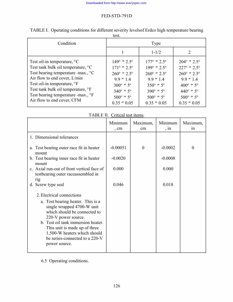
FED-STD-791D
TABLE I. Operating conditions for different severity levelsof Erdco high temperature bearing test.
Type
Condition
1
1-1/2
2
Test o
il-in temperature, °C
Test tank bulk oil temperature, °C Test b
149° " 2.5° 171° 2.5°
177° " 2.5° 199° 2.5°
204° " 2.5° 227° 2.5°
°
earing temperature -max., °C Air flow to end cover, L/min Test oil-in temperature, °F Test tank bulk oil temperature, °F Test bearing temperature -max., °F Air flow to end cover, CFM
"260° " 2.5°
9.9 " 1.4 300° " 5° 340° " 5° 500° " 5°
0.35 " 0.05
"260° " 2.5°
9.9 " 1.4 350° " 5° 390° " 5° 500° " 5°
0.35 " 0.05
"260° " 2.5
9.9 " 1.4 400° " 5° 440° " 5° 500° " 5°
0.35 " 0.05
TABLE II. Critical test items.
Minimum
Maximu
, cm cm , in in m, Minimum Maximum,
1. Dimensional tolerances
a. Test bearing
cr
1,500-W heaters which should be series-connected to a 220-V power source.
outer race fit in heater
mount b. Test bearing inner race fit in heater
mount c. Axial run-out of front vertical face of
testbearing outer raceassembled in rig
d. S
-0.00051
-0.0020
0.000
0 -0.0002
-0.0008
0.000
0
ew type seal 0.046 0.018
2. Electrical connections a. Test bearing heater. This is a
single wrapped 4700-W unit which should be connected to 220-V power source.
b. Test oil tank immersion heater. This unit is made up of three
6.5 Operating conditions.
126
Downloaded from http://www.everyspec.com
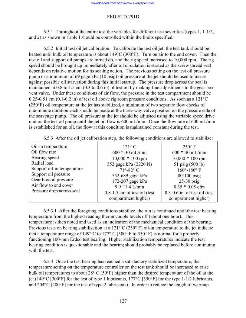
FED-STD-791D
6.5.1 Throughout the entire test the variables for different test severities (types 1, 1-1/2, and 2) as shown in Table I should be controlled within the limits specified.
6.5.2 Initial test oil jet calibration. To calibrate the test oil jet, the test tank should be
heated until bulk oil temperature is about 149°C (3 F). Turn on air to the end cover. Then the test oil and support oil pumps are turned on, and the rig speed increased to 10,000 rpm. The rig speed should be brought up immediately after n is s crewd aling acti ious test op 0 psig) t the usedagainst possible oil starvation during this initial startup. The pres cross thm .3 to 0.6 in) of te king fi nts to the gear box v f air flow e in th artment should be 0 ove rig r re cond soon as( jet has stabilize of tw ow cone-minute duration each should be made at t valve he pr f the he oil pressure at the jet should be adjusted using the variable speed drive unit on the test oil pump until the ce the ow rate of 0 mL/min is established for an oil, the flow at this cond in n t
6.5.3 After the oil jet calibration step, the followi c tions e ed to stabilize:
l
Aieal
121° C
6 /min 10 0 rpm
352 gage kPa (2220 N) C
552-689 gage kPa 172-207 gage kPa
9.9 " .4 L/min 0.8-1.5 est oil (test
comp
250° F
0 mL/m" 100 rp (500 lb)
-180° F 00 psig 30 psig
0.35 " 0.05 cfm 0.3-0.6 in. of test oil (test
com ment higher)
00°
oil circulatio tarted as the s thread seal epends on relative motion for its se on. The prev setting on the il pressure ump or a minimum of 69 gage kPa (1 oil pressure a jet should be to insure
sure drop a e seal is aintained at 0.8 to 1.5 cm (0 st oil by ma ne adjustme
ent valve. Under these conditions o , the pressur e test comp.25-0.51 cm (0.1-0.2 in) of test oil ab oom pressu itions. As a 121 C °250°F) oil temperature at the d, a minimum
he three-way o separate fl
position on thecks of essure side o
scavenge pump. T jet oil flow is 600 mL/min. On fl 60
ition is ma tained consta
ondi
t during the
allow
est.
ng ar Oil-in temperature Oi flow rate Bearing speed
dial loadRa Support oil-in temperature Support oil pressure Gear box oil pressure
r flow to end cover Pressure drop across s
00 " 30 mL,000 10 "
71 °°-82
1cm of tartment higher)
600 " 310,000
in m
51 psig60°1
80-125-
part
tions stabilize, the run is continued until the test bearing temperatu rmocouple levels off (about one hour). This temperatu indication of the mechanical condition of the bearing. Previous tests on bearing stabilization at a 121° C (250° F) oil-in temperature to the jet indicate that a t ° F to 350° F) is normal for a properly functionin Higher stabilization temperatures indicate the test bearing co earing should probably be replaced before continuing with the te
6.5.4 Once the test bearing has reached a satisfactory stabilized temperature, the mperature setting on the temperature controller on the test tank should be increased to raise ulk oi °F) higher than the desired temperature of the oil at the
jet (149 C [300 F] for the test of type 1 lubricants, 177°C [350°F] for the type 1-1/2 lubricants, and 204°C [400°F] for the test of type 2 lubricants). In order to reduce the length of warmup
6.5.3.1 After the foregoing condire from the highest reading there is then noted and used as an
emperature range of 149° C to 177° C (300g 100-mm Erdco test bearing.ndition is questionable and the bst.
teb l temperatures to about 28° C (50
°°
127
Downloaded from http://www.everyspec.com

FED-STD-791D
time re race temperature
(max) to 260°C (500°F). At this point, the three thermocouples attached to the bearing outer race sh
te
re
our
ed oil samples:
AST od 50 m les
quired to reach the desired test oil jet temperature, the Calrod heater should be turned on simultaneously with the change in test tank setting to bring the bearing outer
ould be checked to make sure that the thermocouple indicating the second highest temperature is attached to the Temperature Controller. Improper hookup of the bearing thermocouples will result in poor control of test bearing temperatures.
6.5.5 When the desired test conditions shown in Table I are reached, the test oil flow ra
is again checked twice and adjusted if necessary to obtain 600 mL/min flow at the three-way valve position in the scavenge line. Then the 100-hour endurance test is begun. These data arecorded on a multi-channel strip chart continuously during the course of the test.
6.5.6 Test cycle. The 100-hour endurance test is run so that there is at least a seven-h
shutdown period out of every 24 h of operation. Except for emergency stops, all shutdownsshould be made in accordance with the detailed procedure as outlined in 6.6.4.Warmup time following shutdown periods is considered part of the 100-hour endurance test time.
6.5.7 Used oil analysis. The following laboratory tests are run on the new and us
Test
M meth
L samp
Viscosity at:
0037.8°C (1 °F), cs
98.9°C (210°F), cs Neutralization No.
D 445 D 445 D 664
X X X
w rate checks. Du est oil flow cked
at the three-way valve in the scavenge or cborosilicate glass graduated cylinder should be used to collect the test oil during the flow check. The volume of oil collected in a one- or two-m d check the origflo in
ped
At the completion of the 100-hour endurance test, the test bearing is restabilized at 21°C res
6.5.8 Test oil flo r ting operation the rate should be cheline twice every start-up. F
inute period shoul
onvenience, a 1000-mL,
inal volume w mL/min within "5.0%. In order to prevent too large a drop in test oil level in the tank
during flow checks, a maximum continuous flow period should be 2 min. The hot test oil collected in the glass graduate should be dumped back into the test tank after each flow check. With the friction type variable speed drive unit on the test oil pressure pump, it is not possible toobtain a non-slip drive on the pump after oil pressures reach about 276 gage kPa (40 psig). At this point the test oil will usually have become so viscous it can no longer be effectively pumand the test should be considered ended.
6.5.9 1 (250°F) oil-in temperature to determine the relative change in stabilized temperatucompared to the results obtained at the start of the test. These data can be used to determine the change in frictional characteristics of the bearing resulting from metal wear or excessive oil deposits.
128
Downloaded from http://www.everyspec.com
FED-STD-791D
6.5.10 The rig is then shut down in accordance with the shutdown procedure described in6.6.4.
6.5.11 When the system cools to room temperature, the tank and test oil system sh
be drained into a suitable container so that the volume of test oil remaining can be determAfter the volume of test oil has been measured and recorded, 3.8 L (1 g
ould ined.
al) of the test oil should be poured into a clean container and saved for laboratory analyses.
gh
a
e Test bearing - inner race, rollers and cage assembly. f.
est oil tank - baffle plate. h. Test oil tank - baffle removed.
6.5.13 After the photographs are co detailed v sual de of
these parts to determine the average depth, coverage, consistency, and type of oil deposits, plus the etal wear on the test bearing cage, rollers, roller pockets, and outer race. Rate to 6.7.
the test oil heater should be recorded before the flush is
6
. Timer. e. Test oil heater.
6.5.12 Rig photographs. As soon as possible, the rig should be disassembled. Althou
color is preferred, black-and-white photographs, measuring at least 7.6 H l0.2 cm (3 H 4 in) or slides should then be taken of the following parts:
. Bearing compartment with cover removed - front view. b. Heater mount - rear side. c. Cover plate - rear side. d. Seal plate in housing - heater and bearing removed. . Test bearing - outer race, inside diameter.
g. T
mpleted, a more i inspection is ma
extent of abnormal m deposits according
6.6 PROCEDURES 6.6.1 Flushing procedure.
1. Install a fine mesh (100 mesh) filter at the inlet of the spray nozzle and a coarse mesh
(40 mesh) filter at the inlet of the scavenge pump. It is not necessary to preweigh thefilters.
2. The same type of oil is used to flush the system as used in the test. Service the test oil tank with 7570 mL (2 gal) of test oil.
3. Insure that the tank is vented by means of an exhauster/blower arrangement and that the vent is open.
4. Insure that the test oil supply valve at the inlet side of the pressure pump is closed. 5. The watt-hour meter reading for
begun. . At the control panel turn on the following switches in the order shown:
a. Control panel power. b. Support test oil cart power. c. Stirrer. d
129
Downloaded from http://www.everyspec.com
FED-STD-791D
f. Strip chart recorder. g. Flowmeter timer. h. Doric.
7
ure pump. The pump speed should be maintained such that the pressure is a minimum of 138 gage kPa (20 psig)
10. While the oil is circulating draw two samples of approximately 700 mL each and to the system. If the samples
e oil and begin the flush again. t least 20 min and then turn off the tank heater.
8°C (100°F), close the oil supply
c. Stirrer.
power. h. Control panel power.
14. Drain the test oil tank. Take two samples of the oil (20 and 60 mL). Mark the
ing oil:
st
6.6.2 Preparation for test.
1. order with the date, test number and oil code. 2. esh (100 mesh) filter is installed on the spray
and a coarse mesh (40 mesh) filter is installed on the inlet line of the mp.
. Provide full power (220 V) to the test oil heater. 8. When the temperature of the test oil in the tank exceeds 121°C (250°F) turn on the
pressure and scavenge pumps. Immediately open the test oil supply valve (on the inlet side of the pressure pump) to allow oil to draw to the press
and the flow is 600 " 30 mL/min. 9. Adjust the test oil heater as needed to maintain a temperature of 121°C (250°F) in the
test oil tank.
check for debris. If the samples are clean, return themcontain debris, drain th
11. Circulate the oil for a12. When the test oil tank temperature has cooled to 3
valve on the inlet side of the pressure pump. 13. Turn off the following switches:
a. Pumps b. Timer.
d. Recorder. e. Flowmeter. f. Doric. g. Support test oil cart
samples and the remain
Flush oil B.R. TeTest # Oil Code (PE number) Date
15. After removing the two flush filters, clean and store them.
Update the strip chart recInstall two preweighed filters. A fine mnozzle inlet scavenge pu
130
Downloaded from http://www.everyspec.com

FED-STD-791D
3. . Check the oil level in the test oil and support oil tanks. The charged with test oil at room temperature until the fluid level is
in) above the baffle plate with the pressure and scavenge lines filled. This L" mark or the minimum operating
ions
4. 5. , adjusting it if necessary to maintain a minimum of
6. alves to dynamic and support oil cooler.
8. Ad9. Se ction).
.
and bearing heater er (breaker boxes) to the test oil tank heater, support
eater, test bearing heater, and the bearing drive motor. 13 automatic mode switch. 14 following switches on the control panel:
power. recorder.
ry).
g. h. Water
Load by-pass.
15 e test oil temperature reaches 121°C (250°F) turn on the support oil heater. temperature controllers should be adjusted to obtain 138°C (280°F) and 82°C
l and support oil tanks, respectively. In the test oil tank, the ximum heater skin temperature should not exceed 29°C (85°F) above the test oil
tank target temperature during warmup. Higher temperatures indicate improper should be corrected
before continuing the test program. 1 erature in the test tank reaches 138°C (280°F) turn on the air
supply to the end cover and adjust to approximately 9.9 L/min (0.35 ft3/min). Air
18 upply valve between the test oil tank and the variable speed pressure
pump; it should be wide open.
Close the oil supply valvetest oil tank should be1.3 cm (1/2level should be marked and will establish the "FILlevel during test operation. The expansion of the test oil upon heating to test conditwill establish the "FULL" mark. The support oil tank should contain approximately 23 to 30 L (6 to 8 gal) of a MIL-L-23699 or MIL-PRF-7808 lubricating oil. Insure that the test oil tank vent is open and that any vent line drain is closed. Check the main air supply pressure207 gage kPa (30 psig). Open water v
7. Check dynamic water pressure: it should be 310 gage kPa (45 psig). just the air pressure for the load cylinder to 207 gage kPa (30 psig). t the load valve to the zero load position (clockwise dire
10. Add distilled water to the vapor bottle until the desired level is reached11. Open air bleeds on both sides of the differential manometer for the screw thread oil
seals which should be filled with test oil. gs from the test oil tank heater12. Record the watt hour meter readin
Turn on the electric powmeters. oil tank h
. Turn off
. Turn on thea. Control panelb. Strip chart c. Support test oil cart power. d. Stirrer motor. e. Timer (adjust as necessaf. Test oil heater.
Doric. heater.
i.
. When thThe (175°F) in the test oima
electrical hookup of excessively high supply voltage which
6. When the bulk oil temp
pressure should be held at 34.4 gage kPa (5.0 psig). 17. Start the test oil pressure and scavenge pumps. Insure that the flow is 69 gage kPa
(10 psig) minimum at the test oil jet. The test oil flowrate is 600 " 30 mL/min.. Check the oil s
131
Downloaded from http://www.everyspec.com
FED-STD-791D
19. Start the support oil pumps; there should be at least 414 gage kPa (60 psig) manifold pressure. At the screw thread seal there should be at least 0.8 cm (0.3 in) of oil positive pressure relative to the support oil side (manometer leg to test compartment lower).
. Set and maintain the support oil pressure at 552 to 689 gage kPa (80 to 100 psig) by means of a regulating valve.
. Allow oil temperature at the support scavenge line to reach at 38.8°C l
20
21 east (100°F). bearing
radually with the kPa (51 psig).
ilized:
e
duration each at the three-way mp. The measured volume
0 " 30 mL/min. The hot test oil collected during the flow ediately back into the test oil tank through the fill port
27 r at these conditions with the bearing heater off. If riod, the maximum bearing temperature has exceeded
shut down the rig, install a new test bearing, and repeat items 1 the maximum bearing temperature has not exceeded 177°C (350°F)
d, proceed with the next step. 28. indicator flag to the target temperature on
in
30.
22. Start the bearing drive motor; the bearing speed is preset at 10,000 rpm. (Ifdrive is not constant speed, follow motor operating instructions to bring it up to the necessary speed.)
23. Turn off the load by-pass switch. 24. Apply a load to the test bearing. Increase the load on the bearing g
load controls. The load cylinder pressure should be held at 352 gage25. Continue running until the following conditions have been stab
Test oil-in temperature 121° " 2.5°C (250° " 5°F) st tank bulk oil temperature 138° 2.5°C T " (280° " 5°F)
Air flow, end cover 9.9 " 1.4 L/min (0.35 " 0.05 ft3/min) (corrected) (corrected)
26. Make at least two separate flow checks of one-minuteressure side of the scavenge puvalve position on the p
flow rate should be 60check should be poured imm
apped. and the port rec. Continue running for one hou
end of this peduring or at the 350°F), 177°C (
through 26. If during this perioTurn on the test bearing heater and adjust the temperature controller.
29. Check the three test bearing outer-race thermocouples to make sure that the second highest indicating thermocouple is connected to the temperature controller. Mainta260°C (500°F) on the highest indicating thermocouple Adjust the test oil tank thermal switch so that the target temperature for the type of test being run is met within 30 minutes (minimum) and 60 minutes (maximum). Maximum heater skin temperature should not exceed 29°C (85°F) above test oil target temperature during the warmup period. The nozzle temperature should be maintained at 177° " 2.5°C (350° " 5°F).
Test type 1 1-1/2 2
" 5°F) (390° " 5°F) (440° " 5°F) Target temperature
171° " 2.5°C (340°
199° " 2.5°C 227° " 2.5°C
132
Downloaded from http://www.everyspec.com

FED-STD-791D
Oil-in temperature
149° " 2.5°C (300° " 5°F)
177° " 2.5°C (350° " 5°F)
204° " 2.5°C (400° " 5°F)
33bearin to in sta d
artup u
1. 2. n ottom of the
ure 6.6.2. Open vent drain valve and remov
on5. Co
sho
rat
6.6.
linn
shu , 1-1
B.Test # OD
31. Continue running until the conditions of Table I for the type of test requested have stabilized.
32. Take at least two separate flow checks of one-minute duration at each of the three-way valve position on the pressure side of the scavenge pump. Flow rate should be 600 " 30 mL/min. The hot test oil collected during the flow check should be poured immediately back into the test oil tank through the fill port and the port recapped.
. Continue endurance testing. At the completion of the 100-hour endurance test, the test g is be restabilized at 121°C (250°F) oil-in temperature to determine the relative change
.6.3 Daily bilize temperatures compared to the results obtained at the start of the test. 6 seq ence. st
Update strip chart recorder. Check oil level through visual sight gauge. Add e ough oil so that the btest oil meniscus is even with the mark that was made in step 3 of proced
e all oil from the vent line. 3. Repeat steps 4 to 23 for startup procedure. 4. Turn on test bearing heater and adjust as necessary to reach 260° "2.5°C (500° " 5°F)
the highest reading thermocouple. ntinue running until the conditions have stabilized for the type of test being run as wn in Table I.
6. Make at least two separate flow checks of one-minute duration each at the three-wayvalve position on the pressure side of the scavange pump. The measured volume flow
e should be 600 " 30 mL/min.
4 Daily running procedure.
1. Monitor the strip chart recorder for maintenance of test temperatures within correct operating ranges. Monitor gauges and flowmeters as well.
2. Take two samples of test oil (20 and 60 mL) from the three-way valve in the scavenge e or with an automated system every 10 h (including warmup time along with durance time). The first test sample should be fresh test e oil before the oil is
introduced into the system. If the 10-hour sampling period happens to fall during a tdown period, take the samples just before shutdown or after first reaching type 1/2, or 2 test conditions from next startup of rig. Mark each sample:
R Test
il Code ate
Hour of Sample
133
Downloaded from http://www.everyspec.com

FED-STD-791D
3. Makeup oil should be added fter eac le is taken by adding sufficient quantity of unused test oil to the tank to bring the oil level in the visual sight gage to the full mark.
40Pri at
6.6.5 Shutdown procedure.
2. e
est bearing temperature (maximum) drops to
4. rive motor. d
r, main electrical and water switches, and all air valves.
6
1. This procedure is done in place of the last shutdown. 2 shutdown procedure.
6
1. 2. gage
3. o
4. Reduce load completely and shut off drive motor. 5. ynamatic output shaft stops turning, shut off test pumps, support pumps and
st tank stirrer, main electrical and water switches, and all air valves.
6.6.6 Post-stabilization run.
1. This procedure is done in place of the last shutdown.
immediately a h 80 mL samp
4. The test oil filter changes should be made after shutting down on the first day. If the pressure drop across the 100-mesh filter exceeds 21 gage kPa (3 psig) during operation,the rig should be shut down in accordance with the shutdown procedure under 6.6.5, and a new weighed filter reinstalled. The dirty 100-mesh filter element and the
-mesh filter element are to be weighed and the amount of the weight gain recorded. or to weighing, the 100- and 40-mesh filter screens should be allowed to drain for 1 hroom temperature.
5. Actual running time should conform to the following conditions: a. 17-hour maximum test time between shutdowns. b. Minimum shutdown period of 7 h.
c. Minimum daily running time of 6 h.
1. Shut off bearing and tank heaters. Open air regulated loading valve on console and reduce loading pressure to 172 gagkPa (25 psig).
3. Continue running at these conditions until t204°C (400°F). Reduce load completely and shut off d
5. When the dynamatic output shaft stops turning, shut off test pumps, support pumps anheat, test tank stirre
.6.6 Post-stabilization run.
. Repeat steps 1 through 3 of the
.6.5 Shutdown procedure.
Shut off bearing and tank heaters. Open air regulated loading valve on console and reduce loading pressure to 172kPa (25 psig). Continue running at these conditions until test bearing temperature (maximum) drops t204°C (400°F).
When the dheat, te
134
Downloaded from http://www.everyspec.com
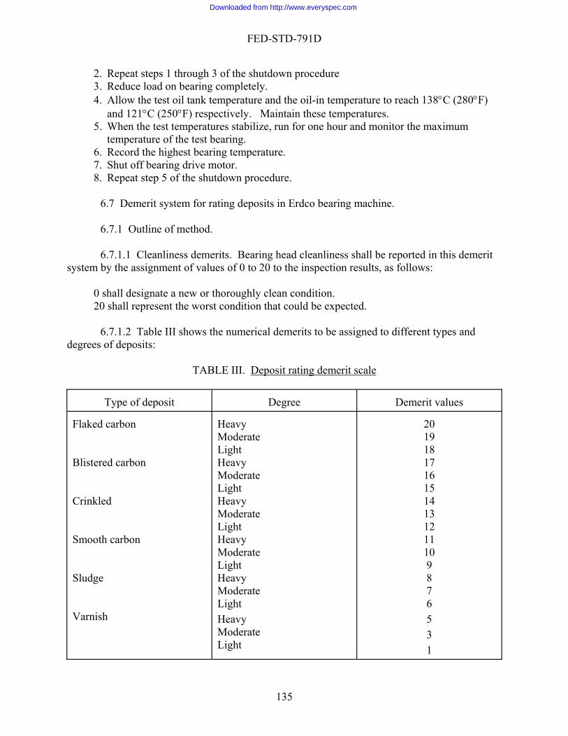
FED-STD-791D
2. Repeat steps 1 through 3 of the shutdown procedure Reduce load on bearing completely. Allow the test oil tank
3. 4. temperature and the oil-in temperature to reach 138°C (280°F)
5.
6. 7. 8.
6
6.7.1.1 Cleanliness demerits. Bearing head cleanliness shall be reported in this demerit system f 0 to 20 to the inspection results, as follows:
clean condition.
degrees o
and 121°C (250°F) respectively. Maintain these temperatures. When the test temperatures stabilize, run for one hour and monitor the maximum temperature of the test bearing. Record the highest bearing temperature. Shut off bearing drive motor. Repeat step 5 of the shutdown procedure.
6.7 Demerit system for rating deposits in Erdco bearing machine.
.7.1 Outline of method.
by the assignment of values o
0 shall designate a new or thoroughly 20 shall represent the worst condition that could be expected.
6.7.1.2 Table III shows the numerical demerits to be assigned to different types and f deposits:
TABLE III. Deposit rating demerit scale
Degree Demerit values
Type of deposit Flaked carb Blistered carbon Crinkled Smo Slud Varnish
Heavy
ht
Light
derate
20 19 18 17 16 15 14
9 8
5 3 1
on Heavy Moderate
Light
Moderate Lig
oth Heavy Moderate
11 10
carbon Light
13 12
Heavy Moderate
ge Heavy Moderate Light
7 6
Heavy MoLight
135
Downloaded from http://www.everyspec.com

FED-STD-791D
Clea 0 n All demerits shall be reported to the nearest whole number
6.7.1.3 Table IV defines deposit types and degrees.
136
Downloaded from http://www.everyspec.com
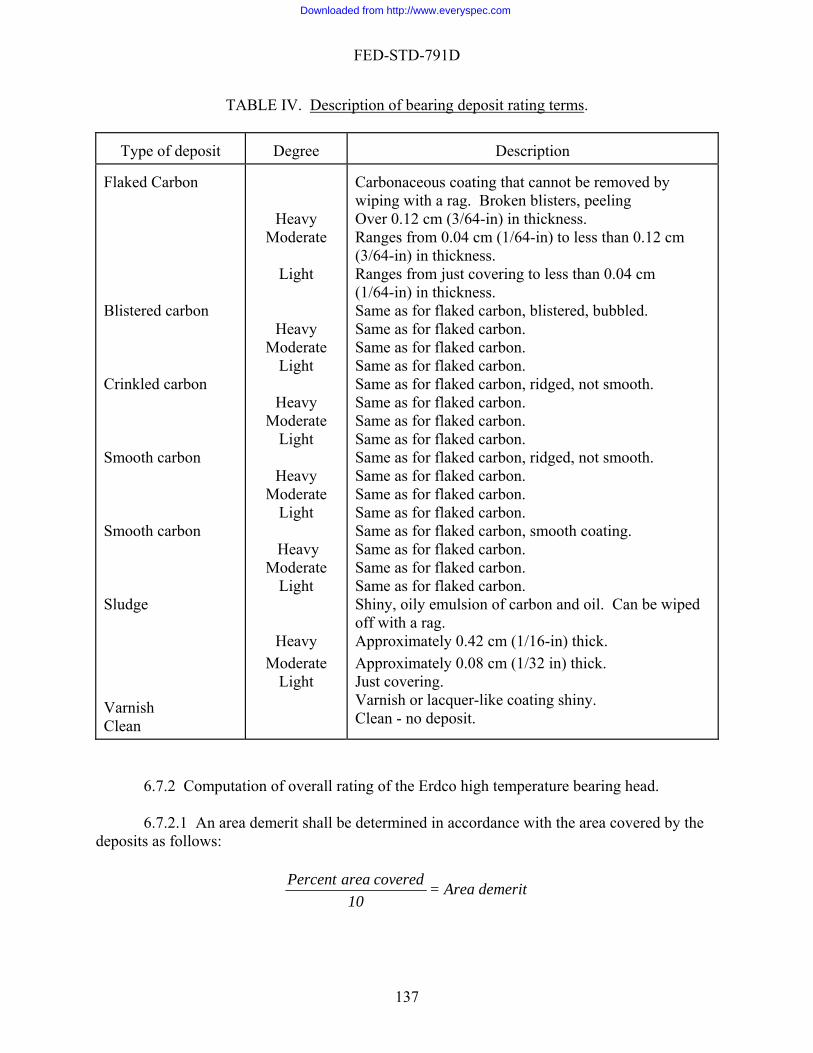
FED-STD-791D
TABLE IV. escription of bearing deposit rating termsD .
Type of deposit Degree Description
Flaked Blistered carbon Crinkled carbon Smooth carbon Smooth carbon Sludge Varnish Clean
Heavy
Moderate
Light
Heavy Moderate
Light
Heavy Moderate
Light
Heavy Moderate
Light
Heavy Moderate
Light
Heavy Moderate
Light
g that cannot be removed by
wiping with a rag. Broken blisters, peeling Over 0.12 cm (3/64-in) in thickness. Ranges from 0.04 cm (1/64-in) to less than 0.12 cm (3/64-in) in thickness. Ranges from just covering to less than 0.04 cm (1/64-in) in thickness. Same as for flaked carbon, blistered, bubbled. Same as for flaked carbon. Same as for flaked carbon. Same as for flaked carbon. Same as for flaked carbon, ridged, not smooth. Same as for flaked carbon. Same as for flaked carbon. Same as for flaked carbon. Same as for flaked carbon, ridged, not smooth. Same as for flaked carbon. Same as for flaked carbon. Same as for flaked carbon. Same as for flaked carbon, smooth coating. Same as for flaked carbon. Same as for flaked carbon. Same as for flaked carbon. Shiny, oily emulsion of carbon and oil. Can be wiped off with a rag. Approximately 0.42 cm (1/16-in) thick. Approximately 0.08 cm (1/32 in) thick. Just covering. Varnish or lacquer-like coating shiny. Clean - no deposit.
Carbon Carbonaceous coatin
6.7.2 Computation of overall rating of the Erdco high temperature bearing head. 6.7.2.1 An area demerit shall be determined in accordance with the area covered by the
deposits as follows:
demerit Area = 10
covered area Percent
137
Downloaded from http://www.everyspec.com
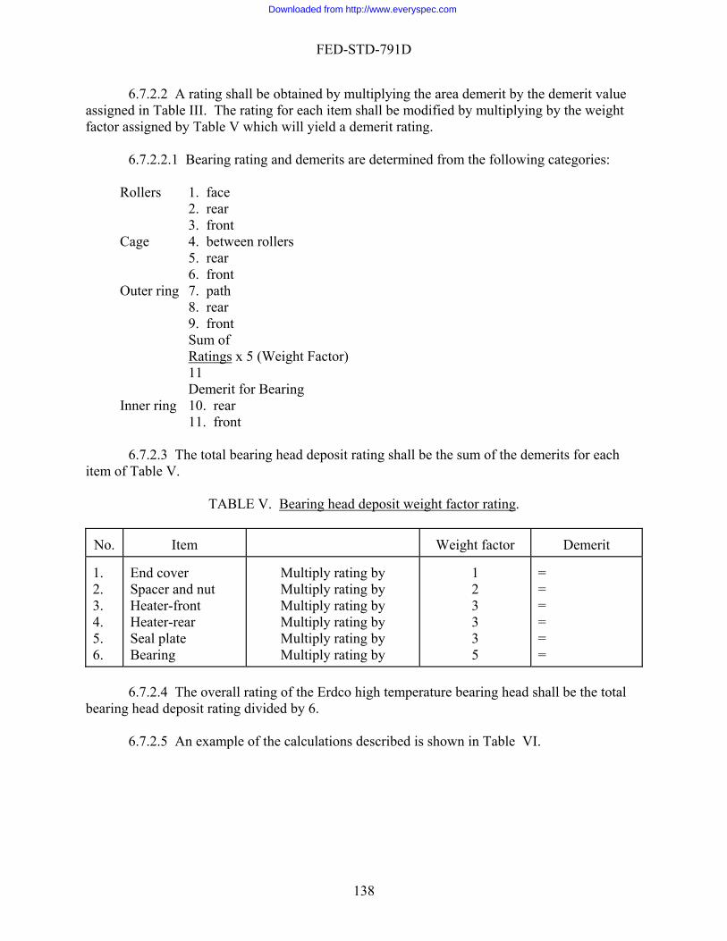
FED-STD-791D
6.7.2.2 A ra e demerit value signed in Table III. The rating for each item shall be modified by multiplying by the weight
f t ble ill y ld a demerit rating.
Bearin rating and dem :
Rollers 1. face 2. rear 3. front
Cage 4. betwee s 5. rear
Outer ring 7. path 8. rear 9. front
of Ratings
ting shall be obtained by multiplying the area demerit by thasac or assigned by Ta
V which w ie
6.7.2.2.1 g erits are determined from the following categories
n roller
6. front
Sum x ht F
11 Demerit fo ing 10. rear 11. front
6.7.2.3 The total bearing head deposit rating shall be the sum of the demerits for each
i
TAB rin rating
5 (Weig actor)
r BearInner ring
tem of Table V.
LE V. Bea g head deposit weight factor .
Item No.
Weight factor
Demerit
1. . .
End cover Spacer and nut Heater-front
al plate
ultip
ltipultip
MultipMultipMultiply rating by
3
3 5
=
= =
234. Heater-rear
Se5. 6. Bearing
M ly rating by 1 = Mu ly rating by 2 = M ly rating by
ly rating by 3 = ly rating by
total
bearing
6.7.2.4 The overall rating of the Erdco high temperature bearing head shall be the head deposit rating divided by 6. 6.7.2.5 An example of the calculations described is shown in Table VI.
138
Downloaded from http://www.everyspec.com

FED-STD-791D
TABLE VI. Example of detailed Rating Item Description Area
demerit Demerit Scale
Rating 6
Factor Demerit
6.7.2.1 6.7.1.2 .7.2.2 6.7.2.2
Table III End cover Clean 1 0 0 1 0 Space and Nut 10% L. sludge
. h
1 9
6 3
6 27 = 33
2
66 90% M
VarnisHeater –front ean
Crinkled
. ed carbon
2.5 .5
2.5 2.5
0 1 12 13
0 2.5 30 32.5 = 65
3
195
25% Cl25% L. Varnish 225%L.carbon 25% MCrinkl
Heater- Rear varnish varnish
% M sludge
1 1
2
1 3 5 7 9
1 3 5 14 45 =68
3
195
10% L 10% M10% H varnish 1 20505 L smooth 5 carbon
Seal-plate 5% M varnish 0.5 3 1.5
=1.5
95% clean 9.5 0 0 1 1.5
Bearing: a. Rollers: (1)
) Rear
b. (4)rol(5) (6)Front
c. ring: (7) path
100% M
arnish
50% M varnis
50%clean 50%L sludge
75% clean 25% M varnish
10 5 5
5
7.5 2.5
3 1 3
0
0 3
30
=50 0 0 30 0
0 7.5
Face (2
(3) Front
Cage: Between lers 100%clean Rear
v50% L. varnish
h 10 0 0 5 6
5 15
50%clean 50% L sludge
5 5
6
30 =60
Outer
(8) Rear 30%M varnish 3 3 9
139
Downloaded from http://www.everyspec.com

FED-STD-791D
d.Inner ring: (10) Rear (11)Front
Bearing( total)
Overall ratings (Average of
1,2
40%H voth
carbon
ean
rnish
arnish udge
5
1
05
/11 =28.25
07.6 / 6 101.2
141 = 607.5
arnish 4 5 20
(9) front
items ,3,4 and 6)
30% L smo
20% cl40%M varnish 40%H va 50% L v50% M sl50% L varnish 50% L crinkledcarbon
3 2 4 4
55
5
9 0 3 5
17
12
27
0 1220 = 95.5 535 5 60=1 310.5
6=
7. C TION
7.1 This sec a e to the te procedur 8. REPORTING
s requ ed by the specific tion. 9. P N
9.1 Precision data have not be develope for this m .
Method prepared by:
Navy - NAPC – 1986
ALCULA
tion is not applic bl st e.
8.1 A ir a
RECISIO
en d ethod
140
Downloaded from http://www.everyspec.com

FED-STD-791D
141
Downloaded from http://www.everyspec.com

FED-STD-791D
FED-STD-791D
142
otes on Figure 2:N
1. 3/8 pipe nipple - 1-1/2 long 40. 1/2 tube H 1/2 npt-male 2. 3/8 pipe union 41. 1/2 pipe npl H 3 long 3. 3/8 pipe nipple - 1-1/2 long 42. 1/2 tube H 1/2 npt-male 4. 3/8 valve (iron) 43. 1/2 three way valve (iron) 5. 3/4 by 3/8 reducer 44. 1/2 tube H 1/2 npt-male 6. 3/4 by 3/8 reducer 45. 1/2 tube 7. omitted 46. 1/2 tube H 3/8 npt-male 8. 3/8 pipe tee 47. 3/8 pipe npt - 1-1/2 long 9. 3/8 tube H 3/8 npt-male 48. 1/4 tube bulkhead connector (steel) 10. 3/8 tubing 49. 1/4 tube bulkhead connector 11. 3/8 tube H 3/8 npt-male 50. 3/8 by 1/8 reducing bushing 12. 3/8 tube H 3/8 51. 3/8 by 1/8 reducing bushing 13. 1/2 tube 14. 1/4 tube tee 15. 1/4 tube 16. 1/4 tube H 3/8 npt-male 17. 1/4 tube H 3/8 npt-male 18. 1/4 tube 19. 1/4 tube tee 20. 1/4 tube 21. 1/4 tube H 1/8 npt-female 22. 3/16 tube H 1/8 npt-male tee (branch T/C modified) 23. 3/8 pipe nipple - 1-1/2 long 24. 3/8 pipe tee 25. 3/16 tube H 1/8 npt-male (T/C modified) 26. 3/8 pipe nipple - 1-1/2 long 27. 3/8 pipe union 28. 3/8 pipe nipple - 1-1/2 long 29. 3/8 pipe nipple - 1-1/2 long 30. 3/8 pipe tee 31. 3/16 tube H 1/8 npt-male (T/C modified) 32. 3/8 pipe nipple - 1-1/2 long 33. 3/8 pipe union 34. 3/8 pipe union - 1-1/2 long 35. 1/2 tube H 1/2 npt-male 36. 1/2 tubing 37. 1/2 tube H 3/8 npt-male 38. 1/2 tube H 3/8 npt-male 39. 1/2 tube1. 3/8 pipe nipple - 1-1/2 long
142
Downloaded from http://www.everyspec.com

FED-STD-791D
Method 3411.1 September 30, 1986
Y OF AIRCRAFT TU S
1.
ethod describes a the thermal stability and co e lubric moisture. The cat the dec n of the steel by the s of the 2.
ed mild steel specimen is placed in a glass thermal stability test cell with a measured amount of test lubricant. Air and moisture are removed from the test cell by heating and shaking under vacuum prior to sealing the tube. The sealed test cell is then heated at a given tem riod of time. The stability of the lubricant is assessed by de change in viscosity, total acid number and by the appearance of the residual lubricant at the end of the heating period. The steel specimen is weighed and examined under a mi ermine changes due to corrosion. 3.
mately 10 mL for each steel corrosion test. 4. AND APPARATUS
te glass test cell having the dimensions given in Figure l is rec er.
, (manufactured by Sta-Warm Electric, Ravena, Oh ay be used in place of the heating bath if so desired. Th ated aluminum block must have a suitable number of openings of the pro cm) and depth (approximately 21 cm) so that the sealed test cel the heater. The temperature of the aluminum block or heating ba ble of being controlled within 1°C ( 2°F) at the test temperature. The tem il sample and the aluminum block or bath shall be kept within 1°C
4.3 Test cell holder – When a heating bath is used, a heavy-wall steel sample tube holder of the proper size to contain the test cell shall be provided for safety reason.
4.4 Becton, Dickinson and Company Yale Luer-Lock (20YL), or equal 20 mL hypodermic syringe with a No. 14 square-tip needle approximately 20 cm (8 in) long.
THERMAL STABILITY AND CORROSIVITRBINE ENGINE LUBRICANT
SCOPE
1.1 This m procedure for determining rrosiveness of aircraft turbin ants in an environment free of air and
mild steel on orrosioalytic effects of omposition of the fluids and the c thermal degradation product lubricant are measured.
SUMMARY
2.1 A weigh
perature for a specified petermining the
croscope to det
SAMPLE SIZE
3.1 Approxi
REFERENCES, STANDARDS,
4.1 Test cell – A borosilicaommended as the sample contain
4.2 Heating bath, 9.5-L (10-qt) capacity
io or equivalent). An aluminum block me resistance wire-heper diameter (approximately 2.0l is completely immersed in th shall be capa
perature gradient between o (2°F).
143
Downloaded from http://www.everyspec.com
FED-STD-791D
4.5. Vacuum pump, capable of re ucin he p sure at le 10 µm of mercury od g t res to ast r less.
4.6 McLeod gauge or other suitable pressure measuring device. 4.7 Water bath °C (175° 5°F) and
sufficient size to contain the test cell.
4.8 Laboratory safety shield, constructed of either safety glass or wire reinforced plastic.
eps, stainless steel.
5. MA
ures, and spill practices of each chemical are xplained.
5.2 Toluene, reagent-grade [2,3,0].
5.3 Acetone, reagent-grade [1,3,0].
5.4 Nitric-sulfuric acid mixture, approximately 1:10 [3,0,2].
ide, 240 grit.
.1.1 Thermal stability is the resistance to permanent changes in properties of the lubricant caused solely by heat.
esulting in a weight chan
, capable of maintaining a temperature of 80° 3
4.9 Balance, sensitivity 0.1 mg. 4.10 Microscope, 20X magnification.
4.11 Forc
TERIALS
5.1 CAUTION – SOME MATERIALS ARE TOXIC AND HAZARDOUS. The materials references and standards listed in this section must be handled carefully. Federal Test Method 10000, Material Handling Safety Precautions, is a reference which lists all toxic and hazardous materials cited in FTMS 791. The synonyms, life hazard, flammability, handling and storage precautions, emergency treatment and mease
5.5 Abrasive paper, silicon carb 5.6 Steel specimens of approximately 0.15 � 0.7 � 7.5 cm made from QQ-S-698 mild
steel shall be used. 6. PROCEDURE
6.1 Definitions
6
6.1.2 Corrosion is any surface damage of the steel specimen r
ge.
144
Downloaded from http://www.everyspec.com
FED-STD-791D
6.2 Preparation of apparatus. .2.1 Cutting test cells - The cells are cut in two, either on an emery cutoff wheel or by
circum
NOT
6scribing the tube with a hot wire about 17 cm from the bottom.
E 1: Circumscribing with a hot wire is preferred because it is cleaner and safer.
6.2.2 Cleaning test cell - Clean the divided test cell by scrubbing with a suitable deterge water and drying in an oven at 105°C (225°F) for l h. The cells can be stored in a desiccator until us
lock or heating bath temperature to 274° 1°C (525° °F).
.2.4 Preparation of steel specimens.
6.2.4.1 Cut samples approximately 0.15 0.7 7.5 cm.
NOTE 2:
nt, rinsing in tap water, heating in hot nitric-sulfuric acid mixture, rinsing with distilled
ed. 6.2.3 Preheat and adjust aluminum b 2 6
� � 6.2.4.2 Remove pits and other imperfections on a fine grinding wheel. 6.2.4.3 Polish with 240 grit silicon carbide paper to remove all surface blemishes from
both sides and all four edges.
In all succeeding steps, handle the steel specimens with filter paper or forceps.
ples by rubbing vigorously with lint-free tissue.
.2.4.5 Wash sample strips in warm toluene, then in warm acetone and allow to air dry.
g.
ate tests are conducted.
shly prepared steel specimen is placed in the lower half of the cleaned cell, hich is then fused to the top half. NOT
6.2.4.4 Clean all metal dust from the sam 6 6.2.4.6 Weigh each specimen to within 0.1 m 6.3 Test procedure. 6.3.1 Duplic
6.3.2 A frew
E 3: Proper annealing of the fused glass cell will prevent rupture and leaks during testing.
oil samples below the capillary end of the test cell with the
aid of the hypodermic syringe.With this sample volume the metal strip is only partially immersed in the oil l
6.3.3 Introduce 6 mL of the
eaving approximately 1.3 cm (1/2 in) exposed.
145
Downloaded from http://www.everyspec.com

FED-STD-791D
6.3.4 Connect the fused test cell containing the oil sample and metal specimen to the vacuum pump. This can be done with vacuum tubing connected through a Kjeldahl connecting bulb, T
6.3.5 Mount the test cell, while still connected to the operating vacuum pump, in a water ba gently
r 20 min. A Thomas-Boerner oscillating platform shaking apparatus may be used. Mounting the tub
:
s joint 24/40, and a No. 1 rubber stopper drilled to hold the thermal stability tube.
th maintained at 80° 3°C (175° 5°F). Degas the cell and its contents while shakingfo
es about 16 cm above the platform. A manifold can be used to evacuate more than one cell at a time. If frothing persists, continue the heating and shaking for another 10 min.
NOTE 4 Certain ester based as well as other type synthetic lubricants are hydrolytically unstable at the test temperature of 274°C (525°F). Therefore, the procedure
pressure in the cell, as measured with a McLeod gauge, or other suitable measuring device, shall be no more than 10 µm before sealing.
.3.6 While the test cell is still under vacuum it is sealed and drawn off at the capillary
approx e 3).
g bath is used, insert the test cell in the steel holder and place the ssembly in the bath.
NOTE 5:
described in 6.3.5 to remove all water before sealing the cell is necessary. The
6imately 3 cm above where it joins the cell body. (See Not 6.3.7 Weigh the test cell to the nearest mg. 6.3.8 Insert the glass test cell in the heater [preheated to 274° 1°C (525° 2°F)] for
period of 96 hours. If a heatina
Safety shields must always be used as a precaution when placing the test cells in
pressures are generated during the test period.
.3.9 At the conclusion of the heating period, remove the test cell and allow to cool to ambien with suitable solvent.
serve the samples for evidence of insolubles, phase separation, interactions between metal and oil, or changes in color of the oil. A significant difference in final c cessitate retesting since color differences indicate improper preparation of one or both of the test cells.
l. Any significant loss in weight indicates leakage of the test cel s
6.3.12 As a safety measure the cells must be cooled before cutting them open because of
the pre
the heater, removing the cells from the heater, and opening the cells. Tremendous
6t temperature. Wipe down the outside of the cell 6.3.10 Visually ob
olor between duplicate tests will ne
6.3.11 Reweigh the test cel
l and the te t must be repeated.
ssure which develops in testing. Any convenient cooling method may be used such as dry ice - acetone, liquid nitrogen, cooling chambers, etc.
146
Downloaded from http://www.everyspec.com
FED-STD-791D
6.3.13 Remove the oil sample and steel specimen by carefully breaking the test cell. This may be accomplished by scribing a mark around the test cell near the top and applying a hot wire to the scratch mark. (See Note 5).
6.3.14 Remove the steel specimen with forceps, wash with a stream of toluene from a
wash bottle to remove oil then dip in two successive warm toluene washes and a final dip in warm acetone. Wipe with lint-free tissue and air dry. Weigh to the nearest 0.1 mg. Using a 20X microscope, carefully examine each steel specimen and note any evidence of pitting or etching either above or below the liquid level.
6.3.16
lubricant after 6.3.17 Determine the neutralization number on both the original and heated lubricant in
accorda
7. CALCULATIONS
.1
where: V1 - viscosiV2 - viscosity after test
.3
6.3.15 Inspect the tube for insolubles and gum deposits.
Determine the viscosity at 37.8°C (100°F) of both the original lubricant and the exposure to heat in accordance with ASTM D 445.
nce with ASTM D 664.
7
100 * V - V = changeviscosity Percent 12 V 1
ty, Initial
7.2 N - N = changeNumber Acid Total 12
where: N1 - Total Acid Number, Initial N2 - Total Acid Number after test
7 12.96
where:
A - B = cmmg/ in specimen steelthe of weight in Change 2
B - M
8.1 The report shall include the following:
etal weight before test in mg A - Metal weight after test in mg
8. REPORTING
147
Downloaded from http://www.everyspec.com

FED-STD-791D
8.1.1 Visual appearance of test cell, insolubles and gum deposits. 8.1.2 Visual appearance of lubricant after test.
osity at 37.8°C (100°F).
9. PRE
.1 Precision data have not been developed for this method.
Method prepared by:
Navy - NAPC-1986
8.1.3 Visual appearance of steel specimen above and below the liquid level. 8.1.4 Change in the neutralization number of the lubricant sample. 8.1.5 Percentage change in visc 8.1.6 Change in weight of the steel specimen in mg/cm2.
CISION
9
148
Downloaded from http://www.everyspec.com

FED-STD-791D
149
Downloaded from http://www.everyspec.com
FED-STD-791D
Method 3430.2 September 30, 1986
COMPATIBILITY CHARACTERISTICS OF UNIVERSAL GEAR LUBRICANTS 1. SCOPE
1.1 This method is used for determining the compatibility of a universal gear lubricant when blended with a reference gear lubricant by observing for precipitation of additive maafter storage. 2. SUMMARY
2.1 The test consists of mixing the reference gear and test gear lubricants, storing the mixture for 30 days, and centrifuging the mixture to determine the percentage of sludge present. 3. SAMPLE SIZE
3.1 Approximately 4 L (1 gal) of the gear oil to be tested. 4. REFERENCES, STANDARDS, AND APPARATUS
4.1 100 mL cone-shaped centrifuge tubes as in ASTM D 96. 4.2 Centrifuge with a diameter of swing (tip-to-tip of whirling tubes) 38.1 to 43.2 cm
to 17 in) and shall be capable of being controlled at a speed of 1500 " 25 rpm.
NOTE 1:
terial
(15
If the available centrifuge does not conform dimensionally to the preferred formthe speed of rotation of the available centrifuge must be adjusted to give the samcentrifugal force at the tips of the tubes as that obtained with the prescrinstrument when operated at 1500 " 25 rpm. The speed to operate the available centrifuge shall be calculated from the formula.
, e
ibed
here: = The 40.7 divided by the diameter in cm of the swing (tip-to-tip of the whirling tubes) of
the available centrifuge. Use 16 as the dividend when the diameter is measured in inches.
4.3 Balance capable of weighing to "1 mg.
1500 * y = rpm
wy
150
Downloaded from http://www.everyspec.com
FED-STD-791D
4.4 Stirring apparatus capable of stirring the contents of a 400-mL at approximately 200 rpm.
4.5 Beakers, 400-mL capacity, tall form, heat resistant glass.
4.6 Forced circulation oven capable of being controlled at 104° " 2.5°C (220° " 5°F) nd 121° 1°C (250° " 2°F).
4.7 Desiccator capable of holding several centrifuge tubes.
synonyms, life hazard, flammability, handling and
emergency treatment and measures, and spill practices of each chemical are xplain
id saturated with potassium
dichrom
5.6 Re
SA 400 Commonwealth Drive Warrendale, PA 15096-0001
. PROCEDURE
6.2 Determine th
ach er oil) to the procedures described in 6.7
through
tall-form beaker
"
a
4.8 Graduated cylinders, 250-mL capacity.
5. MATERIALS
5.1 CAUTION: SOME MATERIALS ARE TOXIC AND HAZARDOUS. The materials references and standards listed in this section must be handled carefully. Federal Test Method 10000, Material Handling Safety Precautions, is a reference which lists all toxic andhazardous materials cited in FTMS 791. Thestorage precautions,e ed.
5.2 Naphtha, in accordance with TT-N-95B, type II [1,4,0]. Caution, Naphtha is flammable.
5.3 Cleaning solution, consisting of concentrated sulfuric acate.
5.4 Distilled water.
5.5 Denatured ethyl alcohol.
ference oils. Information concerning reference oils can be obtained from:
E
6
6.1 Make two compatibility tests with each reference oil.
e residue in each of the reference oils and the sample oil by subjecting e
of the oils alone (not mixed with any oth 6.15. This data will be used in 7.1.
151
Downloaded from http://www.everyspec.com

FED-STD-791D
6.3 Preparation of centrifuge tubes. Clean one centrifuge tube for each compatibility test to be made in the following manner:
b. Clean tubes with cleaning solution.
s with denatured ethyl alcohol.
n oven maintained at 121° “ 1°C (250° “ 2°F) for at least one-half hour.
6.5 Remove the tubes from the oven, place them in a desiccator, and permit them to cool re.
Place 110 “ 1 mL of a reference oil and sample oil in a 400-mL beaker using the me graduated cylinder each time the sample is measured, but a clean graduated cylinder for
each of
.9 Heat the beaker containing the reference oils and test oil mixture in an oven at 121° °
a. Rinse tubes with naphtha.
c. Rinse tubes with distilled water. d. Rinse tube
6.4 Support the centrifuge tubes in an inverted position in a
to room temperatu
6.6 Number each tube, weigh to the nearest mg, and replace tubes in the desiccator until they are to be used.
6.7 Thoroughly shake sample and reference oils prior to sampling. 6.8
sa the reference oils. 6
“ 1 C (250° “ 2°F) for 20 + 1 min. Remove the beaker from the oven and stir (with a mechanical stirrer) the contents while still hot for 5 min.
L of the contents to the weighed centrifuge tubes.
s and store them in an upright position in a darkened area such as a drawer or cup
e conclusion of the storage period, remove the centrifuge tubes from the storag d operate the centrifuge at 1500 “ 25 rpm for a period of 30
6.10 Transfer 100 m 6.11 Cork the centrifuge tube
board at room temperature for a period of 30 “ 1 days. 6.12 At th
e area, place it in the centrifuge, an 1 m“ in.
NOTE 2: In tr
musansferring the centrifuge tubes from the storage area to the centrifuge, care t be taken not to disturb any material which may have separated from the oil.
and decant and discard the superna
ie
6.13 Remove the centrifuge tubes from the centrifugetant oil. Permit the centrifuge tubes to drain in an inverted position at room temperature
for a period of 2 h. Discard the drainings. If the residue is a solid, wash it with naphtha a suffic nt number of times to insure that it is free of oil. decanting is possible
NOTE 3: If the separated material is not sufficiently compacted by the centrifuging to
permit decanting the supernatant oil, continue the centrifuging for 15-minute intervals until
152
Downloaded from http://www.everyspec.com

FED-STD-791D
decantistopper the centrifuge tube and replace it in storage for an
additional 30 days. At the end of the second storage period, proceed as directed in 6.12.
6.14 Pl sition in an oven controlled at 104° " 2.5°C (220° "5°
.15 Remove the centrifuge tube from the oven and place it in a desiccator to cool to room te
ht of the separated material.
NOT
ng is possible. If the material is a liquid at the conclusion of the 30-minute centrifuging period, or if it cannot be compacted,
ace the centrifuge tube in an upright poF) for approximately 2 h.
6mperature. Weigh the tube and contents to the nearest mg. Subtract the weight of the
empty centrifuge tube to determine the weig
E 4: If the residue remains a liquid at the end of the second 30-day storage period, centrifuge the tube as specified in 6.12. Remove the tube from the centrifuge and note the volume of the separated liquids to the nearest 0.05 mL.
S
owing formulas:
7. CALCULATION
7.1 Calculate the percent incompatibility for each test, using the foll
T + R=ility incompatib zero lTheoretica
T) + (R - X =ility incompatib of Evidence
100 * t) 50 +r (50 0.9
T) + (R - X =ility incompatib Percent
wheR =
r = weight p
ple oil.
7.2 Cal st values o
re: weight of separated material in reference oil (g/50 mL of oil). See 6.2.
T = weight of separated material in sample oil (g/50 mL) of oil). See 6.2 X = weight of separated material found in compatibility test. See 6.15.
ercent of additive in reference oil. This information is supplied by the Test Monitoring Center. See 5.6
t = weight percent additive in sample oil. This information is supplied by the manufacturer of the sam
0.9 = assumed specific gravity of both reference oil and sample.
culate and report incompatibility for each reference oil as an average of the twote btained for the reference oil.
NOTE 5: It may be of interest to make a chemical analysis of the residue found in the incompatible oil mixture.
153
Downloaded from http://www.everyspec.com

FED-STD-791D
8. REPORTING
8.1 Report the percent incompatibility of the test gear lubricants. 9. PRE
.1 P cision data have not been developed for this method.
Air Force - AFWAL/POSL-1986
CISION
re9
Method prepared by:
154
Downloaded from http://www.everyspec.com

FED-STD-791D
Method 3432.1 September 30, 1986
COMPATIBILITY OF ELASTOMERS WITH AIRCRAFT TURBINE LUBRICANTS
1. SCOPE
1.1 This method is used for determining effects of aircraft turbine lubricants on elastomers. 2. SUMMARY
2.1 It consists of determining the swelling effect, change in elongatstrength and change in hardness of standard fluorocarbon and fluorosilicone elastomer specimensafter being immersed in the sample for 72 h, at temperatures of
ecimens and 150°C (302°F) for fluorosilicone specimens.
. SAMPLE SIZE
3.1 Approximately 1000 mL of the lubricant to be tested.
. APPARATUS
4.1 Bath; aluminum block or oil bath capable of maintaining sample temperature within °C (1.8°F) of required test temperature. Aluminum block baths will have 5.0 mm ± 1 cm in ickness of insulation. Oil baths will have a cover with openings for immersion of test tubes.
4.2 Test tubes, heat-resistant, 30 cm length and 3.9 cm outside diameter. 4.3 Hanger, specimen, made of stainless steel or nichrome wire. 4.4 Corks, standard size number 19. 4.5 ASTM Die C as described in ASTM D 412. 4.6 Bench Marker as described in ASTM D 412. 4.7 Micrometer as described in ASTM D 412. 4.8 Testing Machine for elongation and tensile strength measurements as described in
STM D 412. 4.9 Grips as described in ASTM D 412.
2240. 4.11 Stamp Pad and Ink as described in ASTM D 412.
ion, change in tensile
175°C (347°F) for fluorocarbon sp 3
4
1th
A
4.10 Durometer, Type A Shore as described in ASTM D
155
Downloaded from http://www.everyspec.com

FED-STD-791D
4.12 Punch, Leather, 0.159 cm (1/16 in) diameter. 4.13 Balance, sensitivity 0.1 mg, suitable for weighing in both air and water.
4.14 Tubing, Pyrex, 0.8 cm O.D.
4.15 Beaker, 400 mL.
ALS
TION - SOME MATERIALS ARE TOXIC AND HAZARDOUS. The aterials references and standards listed in this section must be handled carefully. Federal Test
Method
test rubber sheets, type F-A, conforming to U.S. Air Force Specification ulletin 539.
5.3 Standard test rubber sheets, type FS, conforming to U.S. Air Force Specification
6. PRO
NOTE 1:
5. MATERI
5.1 CAUm
10000, Material Handling Safety Precautions, is a reference which lists all toxic and hazardous materials cited in FTMS 791. The synonyms, life hazard, flammability, handling and storage precautions, emergency treatment and measures, and spill practices of each chemical are explained.
5.2 StandardB
Bulletin 539.
5.4 Cleaning solution, Turbo Alkaline Rust Remover or equivalent. 5.5 Dry cleaning solvent (A-A-59601D). 5.6 Alcohol, ethyl, ACS grade [0,3,0]. 5.7 Acetone, ACS grade [1,3,0]. 5.8 Distilled water. 5.9 Filter paper.
CEDURE
6.1 Clean all glassware as follows:
a. Rinse in dry cleaning solvent, and allow to air dry (see note 1).
Caution. Dry cleaning solvent is both toxic and flammable. Do not breathe its tact with the skin. Keep flames away from the
fumes nor allow it to come in condry cleaning solvent.
156
Downloaded from http://www.everyspec.com
FED-STD-791D
°C (160°F) for 1 h (minimum time), if glassware contains oil deposits from a previous test.
pwater and then with distilled water.
o 105°C (212° to 221° F) and store in dust free location.
.2 Clean suspension device and hooks thoroughly with dry cleaning solvent, wipe with
ir dry and store in a dust free location.
eric
e centered and 0.64 cm (1/4 in) from the end of the specimen. Weigh each test ecimen in air and in water in accordance with method ASTM D 471 (and record weights).
Using ath method ASTM D 2240. Determine the initial hardness of each specimen by
averaging the four readings.
eheat and adjust immersion bath to maintain lubricant sample test temperature of 175° °C (347° 1.8°F) for F-A elastomers specimens and 150° 1°C (302° 1.8°F) for FS elastom is to place a similar test tube containing 140 mL e depth as the test lubricant. A thermo equal to the depth of the small section of the elastom lubricant tubes. The test tube containing the elastom ed into the bath to a depth which places the level of the test lubricant 4.1 cm (1-5/8 in) above the top of the heating medium and not from the top of the i
stomeric specimens in the heated test lubricant by means of a specim
b. Soak in glass cleaning solution at a temperature of 71
c. Wash glassware with laboratory detergent. Rinse thoroughly with ta
d. Dry in an oven at 100° t
6a clean dry cloth, a
6.3 Inspect the sheets of standard stock elastomer for flaws. Sections of an elastomsheet having a flaw will not be used for specimens. Cut four specimens from sheets of standard elastomer stock, with all sheets being from a single production batch, for each lubricant to be tested. Cut the specimens using ASTM Die C as described in method ASTM D 412. Punch a 0.159 cm (1/16 in) hole in each end of the cut elastomer specimens using a leather punch. The hole shall bsp
type A Shore Durometer obtain four Durometer readings (two on each large end) in accordance wi
6.4 Pr 1 er specimens. A suggested method of controlling these temperatures
of lubricant in the bath at the samcouple is then placed in this tube at a deptheric specimens when suspended in the test eric specimens and test lubricant is plac
nsulation of bath covering. 6.5 Immerse the elaen
157
Downloaded from http://www.everyspec.com

FED-STD-791D
158
hanger made from e end permitting o e g parallel and 1.3 cm re specimen hanger to a standard size number 19 cork a d it i , 7.6 cm (3 in) in length, through the cork such that the chimney extends 1.3 cm (1/2 in) above the top f the cork. Insert the second chimney 12.7 cm (5 in) in length, through the cork such that the
chimneated test tube containing the test oil.
Adjust the length of the specimen hanger so that when the cork is placed tightly into the test tube, th
g esh
14
d tensile strength of the elastomeric specimens.
ch
t volume swell for each specimen. Calculate the percent volume swell of the test lubricant as the average of four individual volume swell determinations.
Determine hardness readings on the specimens as described in 6.3. Calculate hardness change for the test lubricant as the difference between the initial hardness and the final hardness.
6.10 Determine elongation and tensile strength of the four specimens in accordance with
method ASTM D 412 using a 2.54-cm (1-in) bench marker. Average the four elongations measurements. Calculate the percent change in elongation, see 7.1.
6.11 Determine the tensile strength of the four specimens in accordance with method
ASTM D 412 and average the four readings. Calculate the percentage change in tensile strength, see 7.2.
stainless steel or nichrome wire. The hanger shall have two hooks at on
n elastomeric specimen to be hung from each hook. The two specimens shall han (1/2 in) apart. Attach the wi
n f w th two lengths of 0.8 cm Pyrex glass tubing (chimneys). Insert one chimney
oy extends 8.9 cm (3 1/2 in) above the top of the cork. Place the cork fitted with the
chimneys, specimen hanger and specimens into the pre-he
e specimens will hang with equal distance of test lubricant above and below the specimens using 140 mL of test lubricant. Hang only two elastomeric specimens in one tube andadjust cork such that specimens do not contact the side of the test tube.
6.6 Remove the elastomeric specimens from the test tube after 72 h with the time startin
when tubes are first inserted into the bath. Place the elastomeric specimens in a beaker of frtest lubricant which is at room temperature and allow to cool for a minimum of 30 min. Remove the specimens from the cooling oil and place them into a beaker of acetone for a minimum ofand a maximum of 20 s. Dry the specimens with filter paper by blotting. Determine volume swell, hardness, elongation an
6.7 Determine a base line for elongation and tensile strength measurements for each
batch of standard elastomer stock. Cut eight specimens in accordance with 6.3 with no more than two specimens being cut from any one sheet. Determine the elongation and tensile strength of each untreated specimen in accordance with method ASTM D 412 using a 2.5 cm (1 in) benmarker. Use the average of these values in determining elongation change and tensile strength change of the oil treated specimens.
6.8 Weigh each oil treated specimen in air and in water in accordance with method
ASTM D 472 and calculate percen
6.9
Downloaded from http://www.everyspec.com
FED-STD-791D
159
9. PRECISION
:
Air Force - AFWAL/POSL - 1986
7. CALCULATIONS
7.1 Calculate the percent change in elongation as follows:
7.2 Calculate the percent change in tensile strength as follows:
100 * n ElongatioInitial
n ElongatioInitial - n ElengatioFinal = change % ,Elongation
100 * StrengthTensile Initial
StrengthTensile Initial - StrengthTensile Final = change % strength,Tensile
8. REPORTING
8.1 Report the percentage change in the elongation and tensile strength.
9.1 Precision data have not been developed for this method.
Method prepared by
Downloaded from http://www.everyspec.com

FED-STD-791D
160
Method 3433 September 30, 1986
COMPATIBILITY OF SYNTHETIC AIRCRAFT TURBINE LUBRICANTS WITH SILICONE RUBBER 1. SCO
synthetic aircraft turbine lubrica ive of commercial seal materials. It determines the extent of deterioration of a silicone rubber standard by the lubricating fluids.
1.2 Advanced synthetic lubricant fluids for aircraft turbine engines with modified
dditive systems must be compatible with materials of construction used in aircraft engines ilicone rubber seals. This test was devised to reveal rubber seal-lubricating
uid compatibility problem areas.
. SUMMARY
2.1 This method provides a procedure for exposing silicone rubber test specimens to the influen ture and time for purpose of
easuring the resulting deterioration by noting the changes in physical properties before and fter immersion in the test liquid.
3. SAMPLE SIZE
3.1 Approximately 500 mL of the lubricant to be tested.
4. REFERENCES, STANDARDS, AND APPARATUS
4.1.1 U.S. Air Force Specification bulletin 539, Standard Elastomer Stocks. 4.2 Apparatus 4.2.1 Oven, gravity convection, 121° 1°C (250° 2°F). 4.2.2 Beakers, tall-form, heat resistant, 600 mL.
4.2.3 Suspension device, glass, for holding test rubber specimens 4.2.4 Hook, stainless steel, for suspending test rubber sheets from balance.
PE
1.1 This method is used for determining the compatibility of nts with a standard silicone rubber composition representat
aparticularly with sfl 2
ce of synthetic lubricants under definite conditions of temperama
4.1 References.
Downloaded from http://www.everyspec.com

FED-STD-791D
161
4.2.5 Balance, sensitivity, 0.1 mg. 4.2.6 Dies and cutters - ASTM die A or equivalent so that width of rubber specimen
4.2.7 Durometer - Standard shore durometer or equivalent.
4.2.8 Micrometer - To measure thickness of rubber.
.2.10 Borosilicate tubing - thermocouple holder closed at one end, 18 cm length 0.3 cm insi
5.1 CAUTION - SOME MATERIALS ARE TOXIC AND HAZARDOUS. The chemic
, and spill practices of each chemical are explained.
silicone test rubber sheets, may be obtained from Naval Air Propulsion Test enter, Trenton, New Jersey 08628. Test sheets should be 15 � 15 cm (6 � 6 in) by 0.19 cm
hick (0 Standard Elastomer Stocks.
c acid [3,0,2] saturated with potassium r sodiu
aphtha [1,4,0] or toluene [2,3,0] ACS.
.6 Acetone, ACS, particle free [1,3,0]. 6. PROCEDURE
.1 Definitions 6.1.1 Tensile stress - the applied force per unit of original cross sectional area of
specimen.
suspended between jaws of tensile tester is 1.27 cm (1/2 in).
4.2.9 Tension testing machines - Scott tensile tester model L or equivalent for rubber
testing. 4 �de diameter � 0.5 cm outside diameter. 4.2.11 Thermocouple and recorder - to record temperature of test oils.
5. MATERIALS
al materials listed in this section must be handled carefully. Federal Test Method 10000, Material Handling Safety Precautions, is a reference which lists all toxic and hazardous materials cited in FTMS 791. The synonyms, life hazard, flammability, handling and storage precautions, emergency treatment and measures
5.2 StandardCt .075 in) as per U.S. Air Force Specification bulletin 539,
5.3 Cleaning solution, glass (concentrated sulfuri
o m dichromate [1,0,1]). 5.4 Methyl alcohol, ACS, particle-free [1,3,0]. 5.5 Solvent - n 5
6
Downloaded from http://www.everyspec.com
FED-STD-791D
162
.2.2 Straight specimens may be prepared where it is not practical to cut ASTM dumbb ). The width should be 1.27 cm (1/2 in) between the jaws which are 2.54 cm (1 in) apart.
.3 Test procedure
.3.1 Volume swell, change in hardness and change in tensile strength are all determined relative to original properties, from the post-test condition of the same specimens. The original tensile
ned. The duplicate specimens should be cut from an area of the sheet which is immediately adjacent to the area from which the test specimens were cu specimen prior to immersion in the oil sample.
6.4 Preparation
.4.1.2 Soak in glass cleaning solution for 2 h (minimum).
.4.1.4 Dry in oven at 100°C (212°F) and store in dust-free location.
oven to maintain a temperature of 121° 1°C (250° 2°F).
mens.
e sheet. Pieces must be cut with the grain of the bber as indicated by two grain marks at the top of the slab.
6.4.3.3 Punch a 0.3175-cm (1/8-in) diameter hole at the center of the 10.16-cm (4-in) side, ab in) from the top edge.
6.4.3.5 Attach the wire suspension device to each piece.
6.2 Test specimen preparation 6.2.1 Test specimens are to be cut using ASTM die A or equivalent. 6ell specimens. The minimum length must be 10.2 cm (4 in
6 6
strength and hardness shall be determined, using duplicate specimens cut from the same sheet from which the test specimens were obtai
t. The original rubber specimen volume is determined from the test
6.4.1 Clean all glassware. 6.4.1.1 Rinse in solvent, rinse with acetone and air dry. 6 6.4.1.3 Rinse thoroughly with tap water, and then with distilled water. 6 6.4.2 Preheat and adjust 6.4.3 Prepare standard test silicone rubber speci 6.4.3.1 Do not buff. 6.4.3.2 Cut three pieces (per 6.2) from th
ru
out 1.905 cm (3/4
6.4.3.4 Mark each piece for identification by cutting small pieces from one or more corners.
Downloaded from http://www.everyspec.com

FED-STD-791D
163
e of silicone test specimens.
suspending it from the balance by its hook. Record the weights.
om the sheet and prevent the sheet from touching the water container. Record the weights.
.4.4.3 Determine (and record) the displacement weight of each piece by subtracting the weight
er specimen to the suspension device, and submerge the sheets in the sam le so that the top edges are no less than 0.635 cm (1/4 in) below the surface. Make certain not touch each other or con-tact the sides or bottom of the beaker.
e oven at 121° 1°C (250° 2°F) for 96 h.
lder and place assembly into oil. The tem erature of each oil should be recorded during the test.
NOTE 1:
6.4.4 Determine original volum 6.4.4.1 Weigh each rubber test specimen and its hook in air to the nearest 0.1 mg by
6.4.4.2 Reweigh (to the nearest 0.1 mg) each sheet while suspended in distilled water at
room temperature, being careful to remove all air bubbles fr
6in water from the weight in air. 6.5 Testing. 6.5.1 Fill a 600-mL beaker with 500 mL of the oil sample. 6.5.2 Attach the rubbpthat the sheets do 6.5.3 Place the beaker in th 6.5.4 Insert a thermocouple in a glass thermocouple hop
Test liquids must not be reused.
.5.5 At the end of 96 h, remove the beaker from the oven and allow it to cool at room
temper
ple and wash in a fresh beaker of methyl alcohol, then rub gently with the fingers to remove all oil from the surface and rinse with a jet sp Caution: Wear protective gloves.
.6.3 Volume swell.
of the rubber test specimens per 6.4.4
Hardness.
6ature for 30 5 min. 6.6 Post test determination of physical properties. 6.6.1 Remove the rubber test specimens from the sam
ray of methyl alcohol. 6.6.2 Allow the rubber pieces to air dry for several minutes. 6 6.6.3.1 Measure the displacement weight
6.6.4
Downloaded from http://www.everyspec.com

FED-STD-791D
164
ermined in accordance with ASTM Method D 2240, Type A durometer.
dness test should be at least 0.3 cm. Therefore, a single-ply thickness of silicone rubber may be used as a cushion.
.
.
ardness value of the test specimen shall be the average value obtained for the three test specimens.
.6.5 Tensile strength.
enter and one at each end of the specimen. The median of the thr measurem ts shall be used as the thickness in calcu
.6.5.3 When rubber specimens of standard thickness are used as per section 5.2 of this tes ximum and minimum thickness does not exceed .0762 cm (0.003 in), it is not necessary to calculate the cross-sectional area for each piece.
imen in the grips of the testing machine, using care to adjust it symmetrically in order that the tension will be distributed uniformly over the cross section. If tension ther, maximum strength of the rubber will not be developed. Start the machine and record the stress at the time of the rupture.
.1 Calculate the percentage change in volume (V) of each rubber sample as follows:
where: V = change in volume, percent. A = ght at conclusion of test, mg. B = displacement weight before immersion in sample, mg.
6.6.4.1 The hardness of the rubber specimen shall be det
6.6.4.2 The thickness of the rubber specimen for the har
6.6.4.3 After swell testing, hardness readings shall be conducted on the end of each test
specimen outside of the area to be used for tensile testing 6.6.4.4 Apply the pressure foot to the specimen. Read the scale 15 s after the pressure
foot is in firm contact with the specimen 6.6.4.5 The h
6 6.6.5.1 Determine the loss in tensile strength by use of Method D 412, Standard Method
of Tensile Testing of Vulcanized Rubber. 6.6.5.2 Three measurements shall be made for thickness; one at the c
ee enlating the cross sectional area. 6
t method and the difference between the ma0
6.6.5.4 Place a spec
is greater on one side of the specimen than the o
7 CALCULATIONS
7
B100 B)- (A = V
displacement wei
Downloaded from http://www.everyspec.com

FED-STD-791D
165
H = change in hardness, percent. C =
.3.1 Observed tensile strength.
F/E = tensile strength in mPa (psi).
unstretched specimen in cm2 (in2).
whe
7.2 Calculate the percentage change in hardness (H) of each rubber sample as follows:
C100 D)- (C = H
where:
hardness before test. D = hardness after test.
7.3 Calculate the change in tensile strength. 7
F = observed force at break in N (lb). E = Cross-sectional area of the
7.3.2 Change in tensile strength, percent
J100 K)- (J = T
re:
T = change in tensile strength, percent. J = tensile strength before test. K = tensile strength after test.
NOTE 2: See sect
ion 6.6.5.3
. REP
8.1 The report shall include the following: 8.1.1 Results calculated in accordance with paragraph 7, Calculations. 8.1.2 All observed and recorded data on which the calculations are based.
8 ORTING
8.1.3 Date of test. 8.1.4 Temperature of test.
Downloaded from http://www.everyspec.com

FED-STD-791D
166
8.1.6 Immersion fluid used. 8.1.7 Exposure period. 8.1.8 Condition of exposed specimen from visual and manual examination.
hardness.
ile test apparatus.
9. PRE
developed for this method.
thod Prepared By:
Navy - NAPC - 1986
8.1.5 Type and dimensions of specimens used.
8.1.9 Test apparatus used for 8.1.10 Type of tens
CISION
9.1 Precision data have not been
Me
Downloaded from http://www.everyspec.com

FED-STD-791D
167
Method 3440.1 September 30 1986
STORAGE SOLUBILITY CHARACTERISTICS OF UNIVERSAL GEAR LUBRICANTS 1. SCO
the storage solubility characteristics of universal gear lu icants. 2. SUMMARY
2.1 Universal gear lubricant is heated at 20°C and observed for separation of additive materia
. SAMPLE SIZE
3.1 400 mL (one pint) of the gear oil to be tested. 4. REFERENCES, STANDARDS, AND APPARATUS
4.1 Apparatus. 4.1.1 100-mL cone-shaped centrifuge tubes as specified in ASTM D 96. 4.1.2 Centrifuge with a diameter of swing (tip-to-tip of whirling tubes) 38 to 43 cm (5 to
in) and shall be capable of being controlled at a speed of 500 " 25 rpm.
NOTE 1:
PE
1.1 This method is used for determiningbr
l after storage at room temperature for a period of 30 days. 3
7
If the available centrifuge does not conform dimensionally to the preferred form, the speed of rotation of the available centrifuge must be adjusted to give the same centrifugal force at the tips of the tubes as that obtained with the prescribed instrument when operated at 500 " 25 rpm. The speed to operate the available centrifuge shall be calculated from the formula:
where: d = the diameter of the swing (tip-to-tip whirling tubes) of the available centrifuge in
entimeters.
4.1.3 Balance capable of weighing to one mg.
1500* d40 = rpm
c
Downloaded from http://www.everyspec.com
FED-STD-791D
168
4.1.4 Beakers, 400-mL capacity, heat re 4.1.5 Desiccator capable of holding seve
Forced circulation oven capable of being controlled at 20° " 1°C.
5.1 CAUTION - SOME MATERIALS ARE TOXIC AND HAZARDOUS. The materia
nce which lists all toxic and azardous materials cited in FTMS 791. The synonyms, life hazard, flammability, handling and
emergency treatment and measures, and spill practices of each chemical are xplained.
5.2 Naphtha (TT-N-95, type II) [1,4,0].
NOTE 2:
sistant glass.
ral centrifuge tubes.
4.1.6 Forced circulation oven capable of being controlled at 105° " 3°C
4.1.7 4.1.8 Cylinder, graduated, 100 and 400 mL.
5. MATERIALS
ls references and standards listed in this section must be handled carefully. Federal Test Method 10000, Material Handling Safety Precautions, is a referehstorage precautions,e
Caution. Naphtha is flammable.
6. PROCEDURE
.1 Perform three solubility tests (three centrifuge tubes) for each oil.
20 °" 5°F) and permit e
6.3 Nu 6.4 Pla
20 " 1 min. 6.5 Remove the beaker from the oven, allow the beaker to cool to 25° " 3°C. Transfer
100 " 1 mL of the oil from the beaker to each of the tarred centrifuge tubes. Cork the tubes. 6.6 Place the centrifuge tubes in an upright position in a darkened area such as a drawer
or cupboard. The temperature should be maintained at 25° 3°C for the length of the storage
storage area to the centrifuge, care must be take parated from the oil. Remove the tubes
6 6.2 Clean centrifuge tubes and dry them in oven at 105° " 3°C (2
th m to cool to room temperature in a desiccator.
mber each tube and weigh it to the nearest mg.
ce 320 mL of the oil into a 400-mL beaker and heat in an oven at 120° " 1°C for
"period, 30 " 1 days.
6.7 In transferring the centrifuge tubes from then not to disturb any material which may have se
Downloaded from http://www.everyspec.com

FED-STD-791D
169
from th the centrifuge at 500 " 25 rpm for 30 " 1 min. If the residue is a solid, wash it several times with naphtha, a sufficient number of times to
nd discard the supernatant oil. Permit the centrifuge tubes to drain in an upside down position at 25° " 3°C for a period
NOT
e storage area, place them in a centrifuge, and operate
assure that it is free of oil. 6.8 Remove the centrifuge tubes for the centrifuge and decant a
of 2 h. E 3: If the separated material in not sufficiently compacted by the centrifuging to
permit decanting the supernatant oil, continue the centrifuging for 5-minute rvals until decanting is possible. If the material is a liquid at the conclusion of
the 30-minute centrifuging period, or if it cannot be compacted, cork the
Place the centrifuge tubes in an upright position in an oven controlled at 05° " 3°C for approximately 2 h.
6.10 Remove the centrifuge tubes from the oven and place them in a desiccator to cool to e nearest mg. Subtract the weight of the empty
termine the weight of the separated material.
centrifu fuge and note the volume of the separated liquids to the nearest 0.05 mL.
ula:
whe
inte
centrifuge tube and replace them in storage for an additional 30 days. At the end of the second storage period, proceed as directed in paragraph 6.7. If there is no visual liquid or solid residue after 30 days, stop the procedure and report zero residue.
6.9
25c
° " 3°C. Weigh the tubes and contents to thentrifuge tubes to de
6.11 If the residue remains a liquid at the end of the second 30-day storage period, ge the tubes as specified in 6.7. Remove the tubes from the centri
7. CALCULATIONS
7.1 Calculate the percent insoluble residue in the sample from the form
samplein additive of percent weight * 0.9
tu centrifuge three the(grams) residue separatedof amount Averageins Percent
= residue oluble
re: 0.9 = assumed specific gravity of the sample:
NOTE 4: The weight percent of additive in the sample can be obtained from the manufacturer
of the sample.
Downloaded from http://www.everyspec.com

FED-STD-791D
170
7.2 Calculate the volume percent liquid separation after the second storage period from the formula:
tube
NOTE 5: The volume percent of additive in the sample can be obtained from the manufacturer of the gear lubricant.
G
port the average amount of separated residue found in the three test samples.
8. REPORTIN
8.1 Re 9. PRECISION
Army - ME - 1986
9. Precision data have not been developed for this method.
Method Prepared by:
samplethe in additive of percent volume centrifuge three the from (mL) liquid separatedAveragePerce = n separatioliquid volume nt
s
Downloaded from http://www.everyspec.com

FED-STD-791D
171
September 30, 1986
BEARING DEPOSITION OF AVIATION TURBINE ENGINE LUBRICANTS 1. SCOPE
tesarious severit bearing temperature for 48 h duration.
for a periodic intervals during the test and at the end of test, samples
mined for both physical and chemical changes when compared to the sample of ew oil ulated deposits on the bearing nd ot system is used for rating dividual areas as well as for obtaining an overall rating. Additional data on relative sludge rming tendencies of oils are obtained by weighing a 100-mesh filter ele
filter element. . SAMPLE SIZE
3.1 Approximately 10 L of test oil.
. REFERENCES, STANDARDS, AND APPARATUS
4.1 The following documents, of the issue in effect on date of invitation for bids or quest for proposal, form a part of this specification to the extent specified herein.
Military specifications
Method 3450
1.1 This method describes detailed procedures used to conduct the bearing deposition
t for evaluating deposit and degradation characteristics of aircraft turbine engine lubricants at y levels of bulk-oil temperature andv
. SUMMARY 2
2.1 A sample of the lubricant is subjected to the required temperature levels
controlled number of hours. At f the oil are exao
n . A visual inspection is made at the end of test of the accumher machine components. A weighted numerical ratinga
info ment and a 40-mesh
3
4
re
:
Military Specification
Title
SAE AMS 5518
Steel, Corrosion Resistant (18-8), Plate, Sheet and Strip
(Copies of specifications, standards, handbooks, drawings, publications, and other
overnment documents required by contractors in connection with specific acquisition functions ould be obtained from the contracting activity or as directed by the contracting activity.)
Gsh
Downloaded from http://www.everyspec.com

FED-STD-791D
172
Drawings:
Air Force Aero Propulsion Laboratory
Dr
awing Title A-B-67043
A-B-67045 A-B-6
A-B-67051
A-B-67053 A-B-6
A-B-68115
A-B-69008 B-B-6B-B-67040
B-B-68049 B-B-6
B-B-68052 B
-B-68055 -B-B-
B-B-68060
Test-Oil Pickup Line, Bearing Test Rig Thermocouple, Bearing Test Rig Test-Oil Jet Plug, Bearing Test Rig
Oil Level Rod Guide, Bearing Test Rig Test-Oil Pump Shaft Extension, Bearing Test Rig Thermocouple Connector, Bearing Test Rig
Oil Level Indicator Tube, Bearing Test Rig Test-Oil-In-Line, Bearing Test Rig Test-Oil Pump Standoff Gasket, Bearing Test Rig Cup-Vent Pipe Blower Assembly, Bearing Test Rig
Details, Bearing Test Rig Test-Oil Accumulator Assembly, Bearing Test Rig
Test Rig Top Plate, Stand, Bearing Test Rig
Rear Panel, Stand, Bearing Test Rig ler, Bearing Test Rig
Blower Modification, Bearing Test Rig e Blower, Bearing Test Rig
pe, Bearing Test Rig Gasket-BlowerTest-Oil-In Filter Housing Assembly, Bearing Test Rig
A-B-67044
7046 A-B-67047 A-B-67049
Test-Oil Jet Assembly, Bearing Test Rig Test-Oil-Out Filter Housing Assembly, Bearing Test Rig Metal Specimen Shaft, Bearing Test Rig
A-B-67052
7054 A-B-67055 A-B-67059 A-B-67060 A-B-67061 A-B-67062 A-B-67063 A-B-68114
Test-Oil Sump Thermocouple, Bearing Test Rig Scavenge Pump Discharge Line, Bearing Test Rig Metal Specimen Spacer, Bearing Test Rig Sump Vent Port, Bearing Test Rig Metal Specimens, Bearing Test Rig Scavenge Pump Modification, Bearing Test Rig Test-Oil Pump Modification, Bearing Test Rig
A-B-69002
7039 Test-Oil-Filter Housing
B-B-67058 Test-Oil Accumulator Details, Bearing
8050 B-B-68051
Door, Stand, Bearing Test Rig Side Panel, Stand, Bearing Test Rig
-B-68053 Air CooBB -68056
68057 Vent-PipFlange-Blower Vent PiB
B-B-68058
Vent Pipe, Bearing Test Rig
B-B-6
C-B-68048 C-B-68054
Frame, Stand, Bearing Test Rig Blower Assembly, Bearing Test Rig
8061 B-6-69001 B-6-69009 C-B-68047
Test-Oil-In Filter Housing Details, Bearing Test Rig Test-Oil Pump Standoff, Bearing Test Rig Sump-Oil Fill Port Adapter, Vent Pipe Blower Assembly, Bearing Test Rig Stand Assembly, Bearing Test Rig
Downloaded from http://www.everyspec.com
FED-STD-791D
173
D-B-6 Test-Oil Sump Components, Bearing Test Rig 7016
(Application or copies sh o Propulsion Laboratory, Attn: AFWAL/POSL, Wright-Patterson Air Force Bas 45433.)
Other
f ould be addressed to the Air Force Aere, Ohio
4.1.1 publications. The following documents form a part of this method to the e ed her he issue in effect on date of invitation for b t for p
Autom
xtent specifi ein. Unless otherwise indicated tids or reques roposal shall apply.
Society of otive Engineers (SAE)
656,
Grade ispersant mineral oil)
AMS 3652, 33660, 3667 AMS 5040 SAE J1966
Polytetrafluoroethylene Carbon Steel Sheet and Strip, Deep Forming Lubricating Oil, Aircraft Piston Engine (Non-d
cation the Society of Automotive Engineers,
I 400 C
ociet
(Appli for copies should be addressed toncorporated, ommonwealth Drive, Warrendale, PA. 15096.)
American S y for Testing and Materials (ASTM)
ASTM D 445
4
inematic and Dynamic
ASTM D 66
Viscosity of Transparent and Opaque Liquids (KViscosities) Neutralization Number of Potentiometer Titration
cation the American Society for Testing and
M 6 Rac 19103.)
he app ring deposition rig which consists of a 1 r bear -oil system, and a specially designed test-oil system.
100-m
(Appli for copies should be addressed toaterials, 191 e Street, Philadelphia, Pennsylvania
4.2 T aratus used in this method is the bea00-mm rolle ing machine, a suitable drive and support
4.2.1 m roller bearing head. The bearing head is divided internally into two main
s own o st-oil system, houses t 100- aring is achieved by s t to th earing mount assembly c circul ked in aluminum oxide. Heater c ovided c ith a er. A watt-hour meter is also contained i circui eater and controller to monitor total power i ar or ouses the externally loaded bearing, D,
ections, as she unshielded
n Figure 1. The front, or test section with its separate tem straight-roller test bearing, A. Heating of the test beh m
upplying hea e bearing outer race. The outer race is secured in a bontaining a ar-wound tubular heating element, B, pacontrol is pr by a West Instrument Corporation type JP controller, or equivalent, inonjunction w manually variable voltage transformn the heater t and is connected between the hnput. The re support section of the bearing head h
Downloaded from http://www.everyspec.com
FED-STD-791D
174
a ft sup ystem. The test and support sections of the bearing head are separated by a screw-thread seal, H, to prevent mixing of the test and sup
nd main sha port bearing, P, together with a separate oil s
port oil. 4.2.1.1 Test-oil jet. The test-oil jet, F, is a nominal 0.1-cm (0.040-in) diameter jet
ocated
ion by connection to a pressurized water line. Water o essure. The jet should deliver
tially solid strea in axial alignment with the jet orifice. Corrections for size and axial s w a jet plug or the entire test-oil jet as required.
Test beari
l at the 12 o'clock position on a 6.668-cm (2.625-in) radius from the center of the bearing machine end cover. Prior to test, the size of the jet is checked with standard plug pin gages, 0.099-cm (0.039-in) diameter gage go, and 0.104-cm (0.041-in) diameter gage no-go. In ddition, the condition of a
the jet is observed under flow conditw through the jet is maintained by a 103.4 kPa gage (15-psig) prfl
an essen mtraightness of jet flo
re made by replacing the
4.2.2 ng. An unshielded 100-mm straight-roller bearing (Rollway P/N RCS 1 uivalent) the
earing head. Load is a of hydra
The tesroller retainer at the top or
nl aded position of the test bearing.
20-560, or eq is mounted on the free end of the shaft in the test-oil compartment of pplied to the bearing shaft, C, and hence to the test bearing, by meansb
a ulically controlled load pis-ton, E, acting through the load bearing, as shown in Figure 1. t bearing is lubricated by a single jet, F, which supplies essentially a solid stream of oil
midway between the I.D. of the outer race and the O.D. of the u o
4.2.3 Test-bearing mount. The bearing is made with an outer race removal feature which
permits the removal of the bearing outer race for cleaning and inspection. Three spot-type t re locate the skin temperature on of the outer race of the test bearing, which is pressed into c se therm ring mount. One of
ocouple leads is connected to the West bearing temperature controller, or quival
hermocouples a d 120° apart (radially) around the I.D. of the bearing mount and indicatethe periphery
ontact with the ocouple junctions when it is installed in the beathese three therme ent.
4.2.3.1 Test bearing outer race thermocouples. Insert fiber glass sheath, 20-gage,
on-con
ving just enough material to insure contact between the heater mount and the bearing outer race. Each of
ir stantan thermocouple wire through the three drilled holes in the heater mount from outside to inside. Silver-solder each thermocouple junction leaving spherical bead on the junction about 0.32 cm (1/8 in) in diameter. Peen each bead back into the hole. Remove excess silver solder lea
the three thermocouple leads is brought out directly through the bearing housing at 120 degree intervals.
4.2.3.2 Thermocouple packing. Polytetrafluoroethylene, or equivalent, is used to
insulate all thermocouple leads where they pass through the housing or end cover fitting. This also applies to the two bearing heater terminals where they pass through the end cover.
4.2.4 Test-oil system. A schematic of the test-oil system is shown on Figure 2. The
test-oil cycle starts at the sump where external heaters maintain the desired bulk-oil temperature. Sump heaters, except for the uppermost band heater which is controlled by a manual switch, are
Downloaded from http://www.everyspec.com

FED-STD-791D
175
peed pressure pump to the 100-mesh filter housing. The lubricant then flows to a tubing cross attached to the filter housing. One leg of the cross contains a bayonet thermo
activates the main drive motor. The system protects against rig tieup as a co
eas the rear drain collects only oil that has gone through the bearing. Both drains feed into a fluid accumu
on Figure 2. The test-oil-in lines and filter housing are wrapped with a single thickness of Fiberfrax insulation, or equivalent, to reduce the differential betwee
cooler, shown on Figure 2, is placed around the test- oil line section preceding the test-oil-out filter to cool the lubricant as required. In some cases, it may be necessary to insulate a porti
controlled by a West type JP controller, or equivalent, with a watt-hour meter connected between the heaters and the controller to monitor total power input. The test oil is pumped from the sump by the variable-s
couple measuring the test-oil-in temperature. One leg transmits fluid pressure to an indicating gage and two pressure safety switch units connected in series. The latter units are set with one unit at a minimum pressure of 34.5 kPa gage (5 psig) and one at a maximum pressure of 241.3 kPa gage (35 psig). In the event of a test-oil pressure excursion outside this range, the applicable safety switch de
nsequence of lubricant starvation in the event of test-oil pump failure, jet plugging, or other equipment malfunction. The third leg of the cross delivers test oil to the jet and then to the test bearing. The test oil is drained from the bearing head at two locations, G, as shown on Figure 1. The front drain collects splash oil which does not pass through the bearing, wher
lator via a single line leading to a three-way valve used for in-line sampling. The test-oil line continues beyond this valve to a second three-way valve which permits routing of the oil to an incorporated test-oil flow measuring system. The test oil next passes through a 40-mesh filter and enters the scavenge pump prior to discharging into the sump.
4.2.4.1 Heat loss from the test-oil system is minimized by placing insulation on the sump
sides, base, and cover as identified
n test-oil-in temperature and sump temperature. Insulating in this manner will normally result in a test- oil-in temperature slightly below the required bulk-oil (sump) temperature. If this differential exceeds the allowed maximum, additional insulation thicknesses are applied. In operation, the test-oil sump is vented to atmosphere.
4.2.4.2 The test-oil entering the sump is normally hotter than the bulk-oil in the sump.
A forced-air
on of the scavenge line with insulating tape to maintain the desired oil temperature entering the sump.
4.2.4.3 Only stainless steel tubing or pipelines and fittings are used in the test-oil system.
The fluid accumulator, filter housings, and sump are similarly constructed of stainless steel. 4.2.4.4 Test-oil sump. The overall configuration and construction details of the test-oil
sump conform to the detailed drawings specified in 4.1.
anhattan A-56 gasket material, or equivalent is employed.
4.2.4.4.1 Sump cover seal. A 0.16-cm (1/16-in) thickness gasket of suitable
dimension is cut to seal between the sump flange and sump cover. Raybestos-M
Downloaded from http://www.everyspec.com
FED-STD-791D
176
4.2.4.4.2 Metal specimens. Metal specimens are mounted within the test-oil sump in order to provide information concerning possible metal attack by the lubricant. The specimen holder is a 0.95-cm (3/8-in) rod mounted on the sump lid and extending 20.32 cm (8 in) into the sump (or approximately 5.08 cm (2 in) below the cold oil level). The specimens are secured to the rod by a 10-32 size screw, 3.81 cm (1-1/2 in) in length. The specimens are individually placed on the screw and separated by spacers of 0.32-cm (1/8-in) thickness and 0.79-cm (5/16-in) O.D. The mounting rod is tapped at the lower end to accept the screw such that the specimens are mounted with their major axis in a vertical plane. The metal specimens are 0.081-cm (0.032-in) thick, 1.905-cm (3/4-in) diameter disks with 0.635-cm (1/4-in) center holes. A five-specimen set is used consisting of the following materials:
Aluminum Titanium Silver Steel Stainless Steel
ASTM B 209, temper T-3 or T-4 8Mn Annealed, 110 ksi (758 MPa) yield strength-UNS R56080 99.9% purity AMS 5040 SAE AMS 5518
A sketch of the metal specimen assembly, indicating the metal specimen order, is shown on Figure 3.
4.2.5 Air system. Water saturated air is metered to the test-oil compartment in the bearing head. The air supply for the test-bearing compartment is filtered shop air connected in the following sequence: air supply to pressure regulator to flow control valve to rotameter to water s rator to water separator column to end cover fitting on bearing head. The air directed through
aturator consists of a 1-in-diameter spherical gas diffuser stone submerged in in a 2 L filtering flask. The flask is initially charged with 1200 mL of water
and is rof a
61-cm (24-in) length of 5.08-cm (2-in) borosilicate or equivalent, glass pipe flanged at both ends. The fla
but com letely, packed with glass wool fiber, Corning Cat. No. 3950, or equivalent.
rot r a flow of 9.91 0.57 L/sec (0.35 0.02 cfm). The procedure is to disconnect the air supply line at the fitting where the air enters the head and then connect the supply line to a wet-test gas meter which in turn discharges to atmosphere. A mercury manometer is located immediately downstream from the rotameter. The
atu the end cover (at 1 o'clock on the same diameter as the test-oil jet) into the bearing
compartment is used primarily to control the pressure drop across the seal so as to insure against oil transfer from the support section into the test-oil section. A 0.64- to 0.32-cm (1/4- to 1/8-in) tubing to pipe fitting, J of Figure 1, should be used for the metered air supply fitting at the end cover. The water sdistilled water with
efilled to this level at each shutdown period during the test. A water separator column is connected downstream of the saturator to remove entrained droplets. The column consists
nges are constructed of suitable aluminum plate with a polytetrafluoroethylene gasket seal between the glass pipe and flange, (see AMS 3652, 3656, 3660, 3667). The column is loosely,
p
4.2.5.1 Air to the test head is metered through a rotameter. Prior to each run, the ameter is calibrated against a wet-test gas meter fo
Downloaded from http://www.everyspec.com
FED-STD-791D
177
settings of the manometer and rotameter are observed and recorded for a wet-test gas meter reading of 9.91 L/sec (0.35 cfm). The air line is then reconnected to the bearing head and the previously observed manometer and rotameter settings are maintained throughout the test.
4.2.5.2 Screw seal. The screw type seal is vented to atmosphere at both the top and
bottom seal housing connections. 4.2.5.3 Connection for seal differential pressure measurement. The lines of the
manometer used to measure the differential pressure across the seal should be connected to the top, front of the bearing head, and to the rear vertical surface of the bearing housing between 11 nd 1 o'cloc , 2.54 cm (1 in) above the junction of the rear case with the main housing. After
startup, there should be no venting of ection, the pipe plug in the top of th ould be remov o allow adjustment of the pressure in the gearbox and, hence, ent of the pressure of the atmosphere of the support-oil syste across the screw seal, which is used to insure against oil transfer fro section to the test-oil section. The required differential is controlled by maintaining a slightly higher test-oil compartment pressure of 0.76 to 1.27 cm (0.3 t-oil colum pport-oil compartment pressure.
4.2.5.4 Sump air venting
a kthe manometer lines. In this conn
e gearbox sh ed and replaced with a small valve t in the support system. The adjustm
controls the pressure drop mm the support
to 0.5 in) of tes n relative to the su
. The sump is vented to the atmosphere through a sump cover
of the line to a gas-flow meter. When the required test conditions are attained after ach st
employ
port as shown on Figure 2. A line connected to the port terminates at a valve which permits connectione artup, the flow rate of the gas discharging from the sump is measured at the valve
ing a portable gas flow rate meter. The speed control of the scavenge pump motor is set to provide a sump gas discharge of 14.16 L/sec (0.5 cfm). During a test, additional measurements of the sump vent gas flow rate should be made when excessive scavenge pump wear or test-oil system air leaks are suspected.
4.2.5.4.1 The procedure for the sump-air venting discussed above is modified for bearing
tests employing sump bulk-oil temperature above 176.7°C (350°F). The valve is closed to the atmosphere and vent pipe-blower assembly is connected to the sump oil-fill port, as shown on Figure 4 to condense the increased oil vapor created in the sump by the elevated oil temperature. Oil vapor/mist condenses in the blower housing and is drained back into the sump. The measurement of the sump vent gas flow rate is made at the valve as previously discussed. However, the vent pipe-blower assembly is removed and the sump-oil port is capped each time the airflow rate is to be measured. After each measurement, the vent pipe blower assembly is replaced at the sump-oil fill port. 5. MATERIALS
5.1 CAUTION: SOME MATERIALS ARE TOXIC AND HAZARDOUS. The
materials references and standards listed in this section must be handled carefully. Federal Test Method 10000, Material Handling Safety Precautions, is a reference which lists all toxic and hazardous materials cited in FTMS 791. The synonyms, life hazard, flammability, handling and
Downloaded from http://www.everyspec.com
FED-STD-791D
178
.2 Dry cleaning solvent (CID A-A-59601D).
etone Corporation 74 Hudson Avenue, Tenafly, New Jersey, Penetone ECS or equivalent) [u,u,u].
.9 Raxbestos-Manhattan A-56 gasket material [0,0,0].
Silver urity
storage precautions, emergency treatment and measures, and spill practices of each chemical are explained.
5 5.3 Carbon remover (Pen
5.4 n-Heptane [1,3,0]. 5.5 Acetone [1,3,0]. 5.6 SAE J1966, lubricating oil. 5.7 Polytetrafluoroethylene tape and gasket material [0,0,0]. 5.8 Fiberfrax insulation [0,0,0]. 5 5.10 Metal specimens [0,0,0].
Aluminum Titanium
ASTM B 209 8Mn Annealed, 110ksi (758 MPa) yield strength-UNS R56080 99.9% p
Steel Stainless Steel
AMS 5040 SAE AMS 5518
5.11 Glass wool fiber, Corning Cat. No. 3950 [0,0,0]. 5.12 400 grit silicon carbide paper [0,0,0]. 5.13 30 grit aluminum oxide [0,0,0].
6. PROCEDURE
6.1 Cleaning procedure.
6.1.1 Test-oil sump. The test-oil sump assembly is completely dismantled for cleaning of all internal components after each test. The sump interior is thoroughly cleaned with a suitable solvent, hand scrubbing, or mild abrasive blast to remove all traces of deposits from the previous test. A new test-oil pumpshaft seal is installed prior to each test.
Downloaded from http://www.everyspec.com

FED-STD-791D
179
2 Test-oil pressure and scavenge pumps
6.1. . The test-oil pressure and scavenge pumps are com letely disassembled and then cleaned to remove all deposits from the previous test.
.1.3 Test-oil accumulator
p 6 . The test-oil accumulator located directly below the bearing
head is disassembled and then cleaned with a stainless steel brush in dry cleaning solvent, or equivalent.
6.1.4 Test-oil lines. All of the straight run test-oil lines and fittings (elbows, tees) are
removed from the test-oil system and hand reamed with stainless steel wire brushes in a bath of dry cle alent. aning solvent, or equiv
6.1.5 Oil filter assemblies. All oil filter housings in the test-oil system are removed and
cleaned ith a stainless steel brush in dry cleaning solvent, or equivalent. A soft fiber brush is usually in a solvent bath.
w adequate in scrubbing the filter elements after a short soaking 6.1.6 Pressure gage line. The test-oil lines leading to the pressure gage and safety switch
units are flushed with approximately 25 mL of test oil prior to each test. Prior to starting the drive m in valve at the end of the line is opened momentarily while the system is under pressure.
6.1.7 Bearing head
otor and to insure correct pressure transmission, the dra
. The bearing head should be disassembled as far back as the seal and
ll of the removable parts, except the test bearing, are cleaned with a suitable carbon remover followed by scouring with No. 400 emery paper and solvent to remove all traces of deposits from the previous est. The entire seal asse ned when the level of deposits on the rear seal plate exceeds a
6.1.8 bearing
a
t mbly should be removed and clea light varnish condition.
Test . A new 1 is used for each 48-hour test. The new bearing is cleaned in solvent to remove In order to facilitate deposit rating, the bearing cage is thoroughly cleaned at three points using a stainless steel wire brush. This rocedure removes the brown coating applied to the cage and allows for a more accurate
t ase metal. The three positions on the cage are arb ately equally spaced. All exposed sides o ering a circumferential distance equal to that between identical points on two succe recleaned in solvent taking care to bearing is dipped in test oil prior to installation in the machine.
ens
00-mm bearing preservative oil.
pevalua ion of cage deposits by initially exposing the bright b
itrarily selected for brushing but are approximf the cage are cleaned at each position, cov
ssive rollers. The bearing isremove all adhering wire bristles. The
6.1.9 Metal specim . Clean and pre polish the specimens by appropriate means of
choi eing reused from a previous test, no pits, etchings, or signs of corrosion should be visible at this point. Finish with No. 400 grit silicon carbide paper, remo
ce. If the specimens are b
ving all marks that may have been left by previous polishing. The specimens should not be handled with bare fingers from this point; handle them only with a clean cloth or paper, or with tongs or forceps. Cotton swab wash the specimens with solvents, first with n-heptane
Downloaded from http://www.everyspec.com

FED-STD-791D
180
and then with acetone, final rinse in clean acetone, air dry and weigh to the nearest 0.1 mg. If ther
NOTE 1:
e is to be any delay before weighing, store under n-heptane until ready.
As a practical polishing procedure, place a sheet of the abrasive paper on a flat
filter paper. An individual abrasive paper should be employed for each metal. Several specimens of the same metal may be polished with one paper.
surface and rub the specimen against the paper with longitudinal strokes, protecting the specimen from contact with the fingers with clean cloth or ashless
6.2 Bearing head assembly. 6.2.1 Main shaft. If the main shaft is not solid, its front end should be plugged with an
aluminum plug. 6.2.2 Screw-thread seal. In installing the seal, the right-hand threads on the O.D. of the
seal mu t be toward the front (test compartment) end of the rig. s 6.2.3 Test-bearing heater mount. The bearing outer race is lightly pressed into the
bearing heater mount with the serial number facing the front of the rig. The recommended fit on the bearing outer race is -0.0005 0.0018 cm (-0.0002 to 0.0007 in). On repeated usage, the I.D. of the bearing mount may become worn and result in a loose fit which might tend to cock the outer race. It may also result in erroneous temperature readings of the bearing outer race. When this happens, the I.D. of the mount may be chrome plated and reground to proper dimension, or that section of the mount replaced.
6.2.3.1 Test-bearing heater assembly. In reassembling the heater mount, care should be
exercised to insure that the heater coil is centered and that at no point should the heater coils come w
bottom to top. The procedure is repeated at frequent intervals until the cavity is filled.
ithin 0.32 cm (1/8 in) of the inside surfaces of the assembly faces. A method of accomplishing this is to assemble the unit without retainer ring; this allows visual inspection of the location of the heater-coils within the assembly. Areas where the coils come within 0.32 cm (1/8 in) of either front or rear inner faces are marked. During final assembly, Transite spacers, or equivalent, (0.32 � 0.64 � 1.27 cm [1/8 � 1/4 � 1/2 in]) are placed at these marked points. The heater mount cavity is repacked with new No. 30-grit aluminum oxide after each test. Suitably small portions of the oxide are added in increments, followed by brisk tapping of the mount exterior to eliminate voids. After adding a portion of the oxide, the mount is raised to the vertical position and tapped with a compositon head hammer over front and rear surfaces working from
NOTE 2: Prior to installation of the heater mount and test-bearing assembly, the oil-jet alignment procedure of 6.2.5 is accomplished.
6.2.3.2
Test-bearing heatermount positioning. Care is exercised to insure that the front d rear vertical faces are parallel to each other and square with the I.D. of the mount. If these an
conditions are not maintained, the concentricity of the bearing's outer race in relation to the shaft
Downloaded from http://www.everyspec.com
FED-STD-791D
181
axthe
T
is may be affected. Before installing the heater mount in the rig, the bearing's outer race rmocouples are checked for continuity.
6.2.4 est bearing. Before installing the test bearing on the hub, it is examined visually
s mechanical defects. If the bearing appears satisfactory, the inner race and cage ressed onto the hub with the serial number facing the front of the rig. The fit of the bearing inner race on the hub is 0.002 to 0.0036 cm (0.0008 to 0.0014 in) peated usage, the O.D. of the bearing hub may become worn and resul
for any obviouassembly is precommended tight. After re t in a loose
earing fit. When this happens, the hub may be chrome plated and reground to proper dimension or repla talled in the bearing head, the shaft is turned by hand to make sure it turns freely. Bearing roughness can usually be detected in this manner. When properl
8 in) off center on the outer race, check for missing shaft assembly parts or an improperly installed bearing outer race. It is important that the lock nut on the test-bearing retainer
from turning on the hub during operation.
bced. After the bearing has been ins
y installed, the rollers should be evenly centered in the outer race. If the rollers are more than 0.32 cm (1/
be tight since it imparts an axial pinch on all of the shaft assembly parts back to the load bearing and in addition helps to prevent the bearing inner race
6.2.5 End cover. Before installing the end cover on the rig, the test-oil jet tube alignment
is verified. The jet positions midway between the outer race I.D. and the cage O.D. Alignment is verified by assembling (outside the machine housing) the heater mount with the outer race installed, the pinch plate, and end cover. The heater mount is fixed by installing the heater terminal nuts and making certain that the mount O.D. coincides with the pinch plate diameter. The end cover mounting bolts are inserted through the cover and corresponding pinch plate holes. The test-oil jet is inserted through its holder and the jet position verified by visual observations from the rear of the heater mount. The test- bearing roller and cage assembly is installed in the outer race through the heater mount rear side and the jet position noted with respect to the cage O.D. Upon subsequent assembly of the bearing machine for testing, a gasket of Raybestos-Manhattan A-56 material, or equivalent, is installed between the end cover and pinch plate.
6.2.6 Check of seal operation. After assembly of the bearing head, the screw thread seal
operation is checked under a 2224 N (500-pound) radial load to the load bearing by applying 351.6 kPa (51-psig) shop air pressure to the loading cylinder and hand rotating the shaft to detect rubbing. If any rubbing occurs, the bearing head is disassembled and a slight amount of material removed from either the screw threads or the seal plate, depending on the location and severity of the rubbing. The material is removed from the seal plate if the rubbing is localized, and the screw thread is ground if the rubbing is severe and occurs over a considerable area.
6.2.7 Miscellaneous joint compounds. No pipe dopes, thread compounds, or gasket
in the assembly of the rig or test-oil system. sealants are used Polytetrafluoroethylene tape, or quivalent (no adhesive) is an effective sealant when applied to pipe threads. e
6.3 Support-oil system. SAE J1966, lubricating oil is used in the support-oil system and
is not normally changed after each run. Drain periods on the support oil are governed by the
Downloaded from http://www.everyspec.com
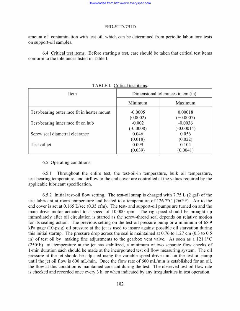
FED-STD-791D
182
amount of contamination with test oil, which can be determined from periodic laboratory tests on support-oil samples.
6.4 Critical test items. Before starting a test, care should be taken that critical test items
conform to the tolerances listed in Table I.
TABLE I. Critical test items.
Dimensional tolerances in cm (in)
Item
Minimum
Maximum Test-bearing outer race fit in heater mount
-0.0005
0.00018
Test-beari
(0.0002) (+0.0007) ng inner race fit on hub
Screw
-0.002 (-0.0008)
-0.0036 (-0.00014)
seal diametral clearance Test-oil jet
0.046 (0.018) 0.099
(0.039)
0.056 (0.022) 0.104
(0.0041)
6.5 Operating conditions.
6.5.1 Throughout the entire test, the test-oil-in temperature, bulk oil temperature, test-bearing temperature, and airflow to the end cover are controlled at the values required by the applicable lubricant specification.
6.5.2 Initial test-oil flow setting. The test-oil sump is charged with 7.75 L (2 gal) of the
test lubricant at room temperature and heated to a temperature of 126.7°C (260°F). Air to the end cov
as a 121.1°C (250°F
tablished for an oil, the flow
er is set at 0.165 L/sec (0.35 cfm). The test- and support-oil pumps are turned on and the main drive motor actuated to a speed of 10,000 rpm. The rig speed should be brought up immediately after oil circulation is started as the screw-thread seal depends on relative motion for its sealing action. The previous setting on the test-oil pressure pump or a minimum of 68.9 kPa gage (10-psig) oil pressure at the jet is used to insure against possible oil starvation during this initial startup. The pressure drop across the seal is maintained at 0.76 to 1.27 cm (0.3 to 0.5 in) of test oil by making fine adjustments to the gearbox vent valve. As soon
) oil temperature at the jet has stabilized, a minimum of two separate flow checks of 1-min duration each should be made at the incorporated test oil flow measuring system. The oil pressure at the jet should be adjusted using the variable speed drive unit on the test-oil pump until the jet oil flow is 600 mL/min. Once the flow rate of 600 mL/min is es
at this condition is maintained constant during the test. The observed test-oil flow rate is checked and recorded once every 3 h, or when indicated by any irregularities in test operation.
Downloaded from http://www.everyspec.com

FED-STD-791D
183
Oil-in
Radial load Support-oil-in-temperature Support-oil pressure Gearbox-oil pressure
irflow to end cover Pressure drop acros
10,000 rpm 200
351.6 kPa (2224 N) [51 psig (500 lb)] 71.1° to 82.2°C (160° to 180°F)
551.6 to 689.5 kPa gage (80 to 100 psig) 6.8 kPa gage (25 to 30 psig)
0.165 ) 0.76 (test
mpart ent h
6.5.3 After the oil flow is set, the following conditions are allowed to stabilize:
temperature Oil flow rate Bearing speed
121.1° . 4°C (250° 1 2°F) 600 20 mL/min
As seal
172.4 to 20 0.01 L/sec (0.35 0.02 cfm
to 1.27 cm (0.3 to 0.5 in) of test oil mco igher)
A run is co ntil the test- b perature from temperature is then noted and u cal condition of the bearing. Previous tes g stabilization at a 121.1 il-in temperature indicate that e range o for a properly fun 100-mm test Higher s temperatures indicate the test-bearing c is questionable, and the bearing s ly be replaced before continuing with th
6.5.3.1 Once the test bearing has reached a satisfactory stabilization temperature, the setting he test-oil heaters is increased to raise the bulk-oil temperature
required value. The uppermost sump band heater is controlled by a manual on-off switch, not the We
is reached, and is deactivated when the desired sump temperature is achin sum
fter the foregoing conditions stabilize, the ntinued u earing tem the highest reading thermocouple stabilizes (about 1 h). This
sed as an indication of the mechani ts na temperatur
on beari°C (250°F) o
148.9°C (300°F) is normal to the jet
f ctioningo n
bearing. tabilization hould probab
nditio test. e
on the West controller for tto
st controller. This heater is used only to accelerate the heating rate when a sump temperature of 232.2°C (450°F), or above, is employed. The heater is not actuated until a sump temperature of 204.4°C (400°F)
ieved. The bearing heater should be turned on simultaneously with the change p heater setting to bring the bearing outer race temperature (max) to the required
temperature. At this point, the three thermocouples attached to the bearing outer race should be checked to make sure that the thermocouple indicating the second highest temperature is attached to the West temperature controller.
6.5.3.2 When the required bearing and sump oil temperatures are reached, the test-oil
flow rate is again checked and adjusted as necessary to maintain 600 mL/min. The sump vent-gas flow is also measured at this time. The scavenge pump motor speed is adjusted to obtain a flow of 0.24 0.01 L/sec (0.5 0.02 cfm).
6.5.4 Test cycle. The 48-hour test is conducted in three 16-hour operating periods. A
fixed shutdown period consisting of a minimum of 4 h and a maximum of 8 h is observed between each 16-hour operating period. Run time begins counting when the test-oil heaters are turned on, including bearing stabilization time. Test time stops when the test-oil heaters are deactivated. Except for emergency stops, all shutdowns are made in accordance with the etailed procedure subsequently outlined. d
Downloaded from http://www.everyspec.com
FED-STD-791D
184
6.5.5 Used oil analysis. The following laboratory tests are run on the new and used oil
s
Test
amples:
ASTM method
Viscosity at 37.8°C (100°F), cSt
10°F), cSt KOH/g
Viscosity at 98.9°C (2Neutralization No., mg
D 445 D 445
D 446, using a pH 11 endpoint
rate check6.5.6 Test-oil flow . During operation, the test-oil flow rate is checked at the incorporated test-oil flow rate measuring system
avenge line as shown on Figure 2. It consists of a three-way valve loc cavenge line
g test-oil flow rate determinations. are is
once every 3 h. The system is located in the ated in the ssc
which permits routing of the oil into an open 1000-mL separatory funnel. The funnel stopcock tube leads to a two-way valve which connects to the scavenge line.
6.5.6.1 The test-oil flow measuring procedure is carried out by setting the three-way
valve to route the oil into the funnel for a period of 1 min, at which time the valve is reset to its normal position. After the oil volume is measured, the two-way valve and stopcock are opened to drain the oil in the funnel back into the scavenge line. The two-way valve and stopcock are closed after the oil is drained in preparation for succeedinC taken to prevent air entering the scavenge line upon draining the separatory funnel.
6.5.6.2 At the completion of the test, while the test oil is still hot, the sump and test-oil
system is drained into a suitable container so that the volume of test oil remaining can be determined. After the volume of test oil has been measured (room temperature) and recorded, 1 L (1 t) of the test oil should be poured into a clean container and saved for laboratory analyses.
6.5.7 Rig photographs. As soon as practical, the rig is disassembled and 10 � 12.7 cm (4
� 5 in) color photographs are taken of the following components:
a. Bearing compartment with cover removed - front view. b. Heater mount - rear side.
rs and cage assembly close-up, 45° angle,
c. End cover - rear side. d. Seal plate in housing - heater and bearing removed. e. Test bearing - inner race, rollers, and cage assembly close-up, 45° angle, 0°
position. f. Test bearing - inner race, rolle
180° position. g. Test bearing - outer race close-up, inside diameter, 0° position (adjacent to
test-oil jet). h. Test bearing - outer race close-up, inside diameter, 180° position.
A typical set of photographs, reduced and in black and white, is shown on Figure 5.
Downloaded from http://www.everyspec.com

FED-STD-791D
185
termine the average depth, coverage, and consistency and type of oil deposits, plus the tent of abnormal metal wear on the test-bearing cage, rollers, roller pockets, and outer race.
6.6 Test Procedure.
6.5.7.1 After the photographs are completed, a detailed visual inspection is made of these
parts to deex
6.6.1 Preparation for test.
1
vel indicator tube. 5
least
1
trolled by maintaining a sligh (0.3 to 0.5 in) of test- c
16. Con e g conditions are stabilized:
Test-oi
bulk-oil temp Airflow e
126.7° 2.8°C (260° 5°F)
. Turn on rig power switches. 2. Turn on support-oil tank heaters and set at 82.2°C (180°F). 3. Turn on multipoint temperature recorder. 4. Charge the test-oil sump with 7.57 L (2 gal) measured at room temperature. The
test-oil expansion upon heating to the required sump bulk-oil temperature will establish the "full" mark which should be noted on the le
. Turn on test-oil heaters and adjust controller to obtain 126.7°C (260°F). 6. Open air bleeds on both sides of the differential manometer which is filled with test
oil. 7. Checkloading valve on console. It should be in the open or zero-load position. 8. When the bulk-oil temperature in the test tank reaches 126.7°C (260°F), turn on the
air supply to end cover and adjust to 0.165 L/sec (0.35 cfm). 9. Start the test-oil pressure and scavenge pumps. Test-oil pressure should be at
68.95 kPa gage (10 psig) at test-oil jet. 10. Start the support-oil pumps. 11. Set and maintain support-oil pressure at 551.6 to 689.5 kPa gage (80 to 100 psig). 12. Adjust the load pressure to 68.95 kPa gage (10 psig) and start the drive motor. 13. Increase rig speed immediately to 10,000 rpm. 4. Close loading valve on console until 351.6 kPa gage (51 psig) is obtained on gage.
15. Close air bleeds on both legs of manometer used for pressure differential checks across the screw-thread seal. The required differential is con
tly higher test-oil compartment pressure of 0.76 to 1.27 cmort-oil compartment pressure. oil olumn relative to the supp
u wintin running until the follo
l-in temp Test-tank
121.1 1.4°C (250° 2°F)
to nd cover 0.165 0.01 L/sec (0.35 0.02 ftm)
17.
system. The measured volume flow rate should be 600 20 mL/min. 18. Con e during, or
.7°C h 17.
Make at least two separate flow checks of 1-minute duration each at the test oil flow measuring
tinu running for 1 h at these conditions with the bearing heater off. If at the end of this period, the maximum bearing temperature has exceeded 176(350°F), shut down the rig, install a new test bearing, and repeat steps 1 throug
Downloaded from http://www.everyspec.com

FED-STD-791D
186
If the maximum bearing temperature has not exceeded 176.7°C (350°F) during this
ot accelerated, temperature rise. Upon reaching the required bearing operating
heater voltage is again adjusted to minimize the bearing temperature variation above and below the control point.
20. Check the three test bearing outer-race thermocouples to make sure the second rmocouple is connected to the West temperature controller.
However, maintain the required bearing operating temperature on the highest ected to a temperature recorder.
lk-oil temperature. erature, bulk-oil temperature, test-bearing
23. oil level
uring system. Flow rate should be 600 20 mL/min. pump
26. n temperature.
tdown period.
period, proceed with the next step. 19. Turn on test bearing heater and adjust controller to obtain the required bearing
operating temperature. Adjust bearing heater voltage to achieve consistent, but n
temperature, the
highest indicating the
indicating thermocouple conn21. Adjust the test-oil heater controller to obtain the required bu22. Continue running until the test-oil-in temp
temperature, and airflow to end cover are stabilized to the applicable specification values. Mark the level indicator tube to show the full position. All subsequent checks are made in reference to this point.
24. Take at least two separate flow checks of 1-minute duration, each at the test-oil flow meas
25. Measure the sump vent-gas flow at the exhaust valve and adjust the scavenge motor speed to obtain 0.24 0.01 L/sec (0.5 0.2 cfm) vent-gas flow. Adjust airflow to air cooler to maintain specified test-oil retur
27. Continue running to complete the 16-hour operating period, shut down the rig in accordance with 6.6.3 and observe a shu
6.6.2 Operating Procedure. 6.6 2.1 Record the following operational data at 30-. min intervals:
b. Timc. Lod. Te
atiotrol setting - scavenge pump. g. ressure - test ve us suppoh. tameter scale. i. (3 thermocouplesj. ture. k. Test-oil-in temperature.
m. Te
o. Sup. Su
a. Test hours (count from the time when the test-oil heaters are turned on until turned off).
e and date. ad-oil pressure. st-oil pressure.
e. Ratiotrol setting - test-oil pump. f. R
Seal differential p rs rt section. Airflow to end cover - ro
tureTest-bearing temperaTest-oil sump tempera
).
l. Test-oil-out temperature - end cover side. st-oil-out temperature - seal side.
n. Test-oil return temperature. pport-oil-in temperature. pport-oil-out temperature.
Downloaded from http://www.everyspec.com

FED-STD-791D
187
q. W r. W 6.6.2.2 Take 40-mL samples of test oil from
en
6.6.adding suff il level to the full mark. Makeup oil is not ad amakeup oilperiod.
ents
during each(185°F), we
att-hour meter, test-oil sump heater. att-hour meter, test-bearing heater.
three-way valve in scavenge line every 4 h (including warm-up time along with durance time).
2.3 Makeup oil should be added immediately after each 40-mL sample is taken by icient quantity of unused test oil to bring the o
ded fter the sample withdrawal at 16 and 32 h. The rig is shut down at these times, and is added after stabilization of test conditions for the subsequent 16-hour running
6.6.2.4 Test-oil-in and test-oil-out filters are replaced with clean, pre-weighed elem 4-hour down period. The used filter elements are allowed to drain for 1 h at 85°C ighed, and the weight gain recorded.
6.6.3 Shutdown sequence. ut off test-bearing and sump heaters. a. Sh
c. Co ture (maximum) drops to
d. Rer, main
6.6.4 Startup sequence
b. Adjust loading valve on console and reduce load pressure to 172.4 kPa gage (25 psig). ntinue running at these conditions until test-bearing tempera
204.4°C (400°F). duce load to 68.95 kPa gage (10 psig) and shut off drive motor.
e. When drive shaft stops, shut off test-oil pumps, support-oil pumps, and heateelectrical and water switches, and all air valves.
.
a. Turn on rig power switches and support-oil heaters in sufficient time to attain the
b Turn on multipoint temperature recorder.
g until the maximum bearing temperature stabilizes within 2.8°C (5°F) readings taken at 2-min intervals. This stabilization normally
30 min after starting the drive motor. f 6.6.1.
ump level indicator to the full mark.
82.2°C (180°F) temperature prior to startup. .
c. Follow step Nos. 5 through 17 of 6.6.1. d. Continue runnin
between successiveoccurs within 20 to
e. Follow step Nos. 19 through 22 of. Add sufficient new oil to bring the sg. Follow step Nos. 24 through 27 of 6.6.1.
6.7 Deposit rating system. 6.7.1 Outline of method. 6.7.1.1 Deposit demerits. Bearing machine cleanliness is reported in this deposit demerit
system of 0 to 20. Identify the different types and thicknesses of depos te a new or clean condition; 20 shall represent the worst condi
by the assignment of values its as follows: 0 shall designation that could be expected.
Downloaded from http://www.everyspec.com

FED-STD-791D
188
degrees o
6.7.1.2 Table II shows the numerical demerits to be assigned to different types and
f deposits.
TABLE II. Demerit rating numbers used for numerically describing deposits.
Demerit rating number
Deposit type
Light
Medium
Heavy
Smooth carbon CrinkleBlisteFlaked
9 12
7 10 13 16
8 11 14 17
Varnish Sludge
1 6
3
5
d carbon red carbon 15 carbon 18 19 20
.7.1.3 Table III de6 fines deposit types and severities.
are visua sit demerit rating:
b. Spacer and nut (considered to be one piece). it types and degrees
6.7.1.4 The following six major items in the test bearing section of the bearing machine
lly inspected and rated to obtain the overall depo
a. End cover.
Table III. Description of depos .
De Description posit type Degree
Varn Slud Smoo
Medium
in color, translucent Black in color, opaque
ulsion of carbon and oil usually light brown in color. Remove by wiping with a rag.
Less than 1/64 in thickness 1/64 to 3/64 in thickness 3/64 in thickness or more
3/64 in thickness or more
ish ----- Light
Medium
Varnish or lacquer-like coating, shiny Light gold or yellow in color, translucent Brown or dark brown
ge ----- Shiny, oil em
th carbon
----- Light
Heavy 1
Light
Heavy
1
Medium Heavy
Carbonaceous coating not removable by wiping with a rag Less than 1/64 in thickness 1/64 to 3/64 in thickness
Downloaded from http://www.everyspec.com

FED-STD-791D
189
Crink
Blisteredcar
carbon
Light
Medium Heavy
Light Medium Heavy
-----
Light
Medium Heavy
smooth Less than 1/64 in thickness 1/64 to 3/64 in thickness 3/64 in thickness or more
d
ckness ess
3/64 in thickness or more
Same as for smooth carbon, flaked or broken blisters, peeling
Less than 1/64 in thickness 1/64 to 3/64 in thickness 3/64 in thickness or more
led carbon
----- Same as for smooth carbon, ridged or uneven surface, not
----- Same as for smooth carbon, blistered, bubblebon
Flaked
Less than 1/64 in thi1/64 to 3/64 in thickn
1 Some difficulty may be encountered in distinguishing between light smooth carbon deposit
d glossy and upon scraping in smooth carbon deposit appears d
and heavy varnish. The varnish deposit appears shiny anicates a tacky consistency or thin, brittle flaking. Thed
ull and lusterless and upon scraping reveals a grainy consistency. c. Heater-mount front. d. e. f. Test bearing.
the six ma
nd cover: The ce of t e end covtire surface asher (all
considered to be one piece) normallyc. Heater-mount front: The surface of the plane
of the end cover and normally exposed to test oil. The portion of the heater-mount front o
Heater-mount rear: The surfof the end cover and normally expose
e. Seal plate: The visible surface of the sea place, normally exposed to tes
f. Test bearing: The test bearing is divided into four section for rating purposes. These ions ar rn bro
1. Fro2. Re
Heater-mount rear. Seal plate.
6.7.1.5 The specific areas rated on each of jor items are as follows:
a. Eb. Spacer and nut: The en
surfa h er normally exposed to test oil. of the spacer, nut, lock-washer, and flat w exposed to test oil. the heater arallel to -mount front which is p
which contacts the heater-md.
unt retainer is not included in the area rated. ace of the heater-mount rear which is parallel to the plane
d to test oil. l plate, with the slinger in
t oil.
four sect e in tu ken down into eleven specific areas as follows:
Rollers nt
ar
Downloaded from http://www.everyspec.com

FED-STD-791D
190
3. Contact Surface Cage
4. Front 5. R6. Ou
ear tside diameter surface
O ter u race
7. Front 8. Rear 9. Contact surface
Inner race
10. F11. R
ront ear
mputatio verall de6.7.2 Co n f oo posit rating.
6.7.2.1 An area rating is determined d by the deposit
as follows:
Surface deposits are not normally subdivided into areas smaller than 5%.
each inspected item is obtained by multiplying the area demerit rating assigned in Table II and summing all such results to account for 100% inspected. In the event that more than one type of deposit is present on
e ar , the rating for that area item is the total of the individual rating values. he de ble ratings, ch as
um o then modified by multi
t demeri according to the area covere
covering demerit area = 10
covered area Percent
6.7.2.2 A rating for t value by the demeri
of the item being ea being inspectedth
T posit rated is that which is visible without the removal of another deposit. Dou sludge over varnish, are not used. The rating for the test bearing is obtained by taking asu
s f the 11 rated areas and dividing by 11. The rating for each item is plying by the assigned weight factor which will yield a demerit rating as follows:
Major item Rating Factor
Demerits
End SpaceHeater mHeater mSeal platTest b
X5 1
1
3X3
X5
r and nut ount front
X
X1
1
X
2 3
2X
ount rear e
X
2X3
2
3 3X4 4
earing X 5 5X6 6
6.7.2.3 The overall deposit rating is the sum of the major item demerits divided by six.
Downloaded from http://www.everyspec.com
FED-STD-791D
191
6.7.2.4 After test, a rating of the interi l and bottom is made. This rating, which is not included in the calculation of the overall test rating, is reported in terms of the type of surface depos sent and the are by each deposit rather than numerical demerits.
6.8 Metal Specim ion. 6.8.1 After test, the metal corrosion s embled from the holder and
solvent-rinsed to remove residual test oil. ( stored in n-heptane if final processing is delayed). T al specime tane swabbed using a series of cotton swabs or pads until clean pads are noted. The coupons are then rinsed in clean n-heptane and cetone, air-dried, and weighed to the nearest 0.1 mg.
reported in mg/cm2 ignoring edge areas in the cal
7. CALCULATIONS
7.1 This section is not applicable to the test procedure.
Method prepared by:
Air Force-AFWAL/POSL - 1986
or test-oil sump wal
its pre a covered
en Preparat
pecimens are disasshe specimens are T
he individu ns are n-hep
a .8.2 Significant specimen weight change is6
culation of exposed surface area. A significant weight change is defined as a weight variation of 0.20 mg/cm2 or more.
8. REPORTING
8.1 As required by the specification. 9. PRECISION
9.1 Precision data for this test is reported in AFAPL-TR-70-8, Volume I, Deposition and Degradation Characteristics of Aircraft Turbine Engine Lubricants. Copies are available through DDC (No. AD-871991).
Downloaded from http://www.everyspec.com

FED-STD-791D
192
Downloaded from http://www.everyspec.com
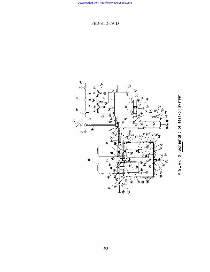
FED-STD-791D
193
Downloaded from http://www.everyspec.com
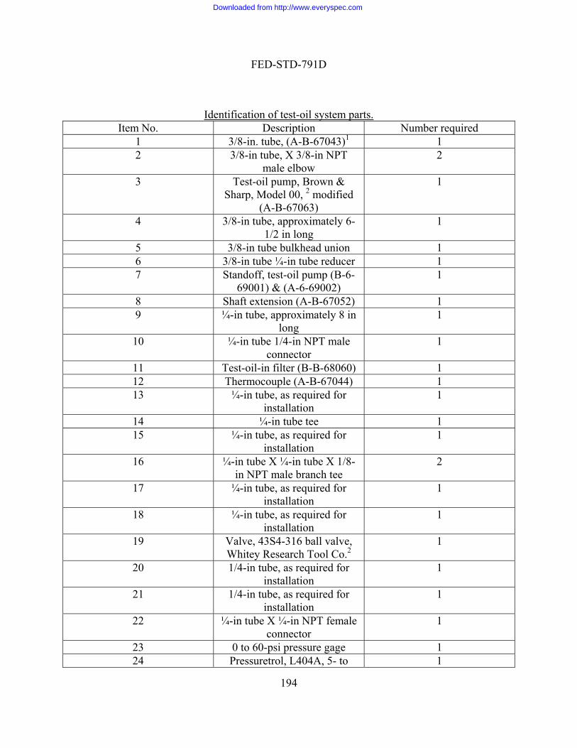
FED-STD-791D
194
Identification of test-oil system parts.
Item No. Description Number required 1 3/8-in. tube, (A-B-67043)1 1 2 3/8-in tube, X 3/8-in NPT
male elbow 2
3 Test-oil pump, Brown & Sharp, Model 00, 2 modified
(A-B-67063)
1
4 3/8-in tube, approximately 6-1/2 in long
1
5 3/8-in tube bulkhead union 1 6 3/8-in tube ¼-in tube reducer 1 7 Standoff, test-oil pump (B-6-
69001) & (A-6-69002) 1
8 Shaft extension (A-B-67052) 1 9 ¼-in tube, approximately 8 in
long 1
10 ¼-in tube 1/4-in NPT male connector
1
11 Test-oil-in filter (B-B-68060) 1 12 Thermocouple (A-B-67044) 1 13 ¼-in tube, as required for
installation 1
14 ¼-in tube tee 1 15 ¼-in tube, as required for
installation 1
16 ¼-in tube X ¼-in tube X 1/8-in NPT male branch tee
2
17 ¼-in tube, as required for installation
1
18 ¼-in tube, as required for installation
1
19 Valve, 43S4-316 ball valve, Whitey Research Tool Co.2
1
20 1/4-in tube, as required for installation
1
21 1/4-in tube, as required for installation
1
22 ¼-in tube X ¼-in NPT female connector
1
23 0 to 60-psi pressure gage 1 24 Pressuretrol, L404A, 5- to 1
Downloaded from http://www.everyspec.com
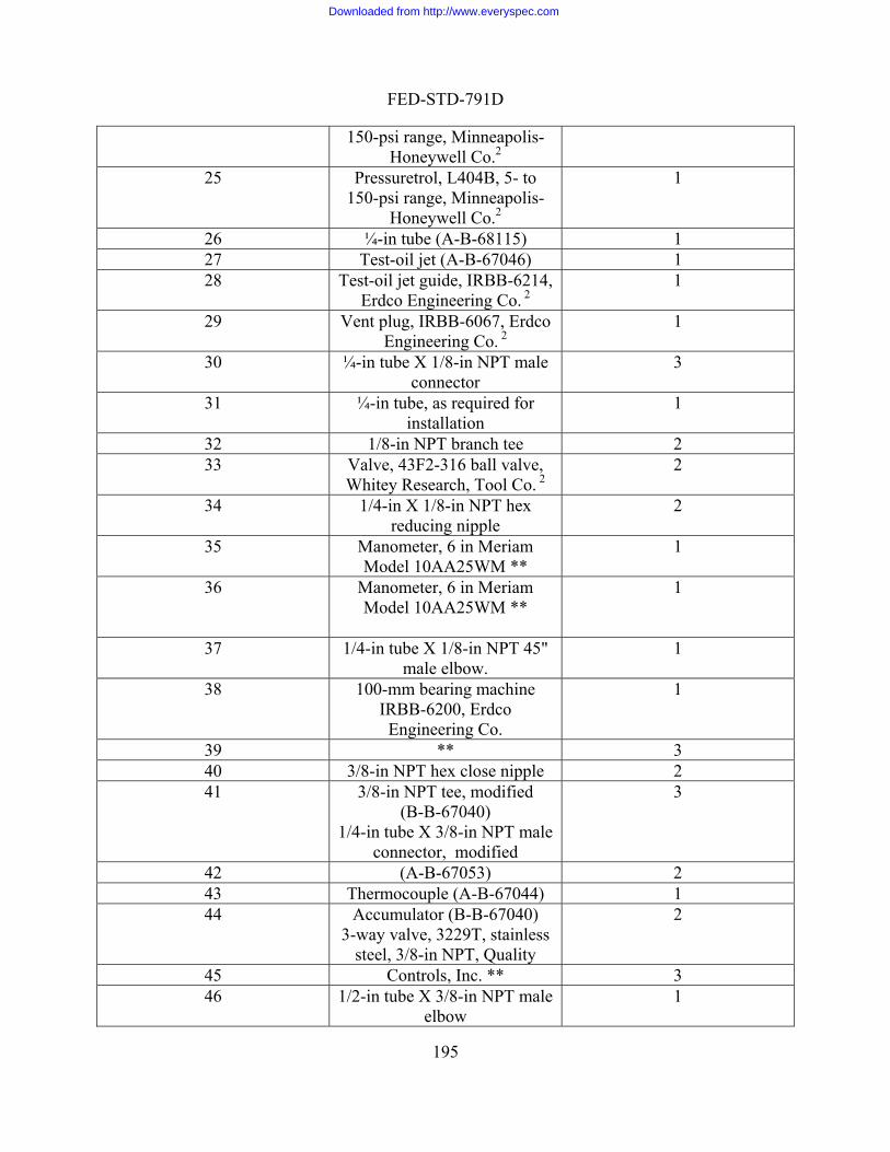
FED-STD-791D
195
150-psi range, Minneapolis-Honeywell Co.2
25 Pressuretrol, L404B, 5- to
Honeywell Co.2
1 150-psi range, Minneapolis-
26 ¼-in tube (A-B-68115) 1 27 Test-oil jet (A-B-67046) 1 28 Test-oil jet guide, IRBB-6214, 1
Erdco Engineering Co. 2
29 Vent plug, IRBB-6067, Erdco E 2
1 ngineering Co.
30 ¼-in tube X 1/8-in NPT male connector
3
31 ¼-in tube, as required for installation
1
32 1/8-in NPT branch tee 2 33 Valve, 43F2-316 ball valve, 2
Whitey Research, Tool Co. 2
34 1/4-in X 1/8-in NPT hex reducing nipple
2
35 Manometer, 6 in Meriam Model 10AA25WM **
1
36 Manometer, 6 in Meriam Model 10AA25WM **
1
37 1/4-in tube X 1/8-in NPT 45" 1 male elbow.
38 100-mm bearing machine IRBB-6200, Erdco
Engineering Co.
1
39 ** 3 40 3/8-in NPT hex close nipple 2 41 3/8-in dified
1/4-in tube X 3/8-in NPT male
3 NPT tee, mo(B-B-67040)
connector, modified 42 (A-B-67053) 2 43 Thermocouple (A-B-67044) 1 44 Accum 7040)
3-way valve, 3229T, stainless steel, 3 uality
2 ulator (B-B-6
/8-in NPT, Q45 Controls, Inc. ** 3 46 1/2-in tube X 3/8-in NPT male 1
elbow
Downloaded from http://www.everyspec.com

FED-STD-791D
196
47 1/2-in tube (as required for sampling)
1
48 1/2-in tube, 8 in long 3 49 1/2-in tube X 3/8-in NPT male
connector 1
50 3/8-in nipple, 4 in long 1 51 Funnel, 7253-20, Ace Glass
Co. ** 1
52 Clamp, 7666-15, Ace Glass Co. **
1
53 Stainless steel socket, 7658-40, Ace Glass Co. **
steel, 1/ uality 2-way valve, 2229S, stainless
2-in NPT, Q
1
54 Controls, Inc., ** 1 55 1/2-in tube X 1/2-in NPT male 1
elbow 56 1/2-in tube, approximately
2-1/2 in long 1
57 1/ 3 2-in tube, approximately 2in long
1
58 1/2-in tube union tee 1 59 1 1 /2-in tube, approximately
2-1/2 in long 60 1 1/2-in tube union elbow 61 1/2-in tube, approximately 42 1
in long 62 Air cooler (B-B-68053) 1 63 Te )st-oil-out filter (A-B-67047 1 64 1/2 ly 1 -in tube, approximate
2-1/2 in long 65 1/2-in tube X 3/8-in NPT
female X 1/2-in long tee 1
66 1/2-in tube, approximately 2-in long
1
67 1/2 ly
1 1/2-in tube bulkhead union. -in tube, approximate
7-1/2 in long 68 1 /2-in tube X 1/2-in NPT male
elbow 2
69 Sharpe, Model 2S** equipped
with Viton O-ring in
1 Scavenge pump, Brown &
mechanical seal and special
Downloaded from http://www.everyspec.com
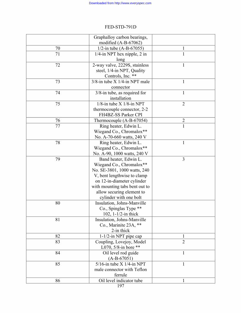
FED-STD-791D
197
Graphalloy carbon bearings, modified (A-B-67062)
70 1/2-in tube 7055) 1 (A-B-671 1/4-in NPT hex nipple, 2 in
long 1
72 2-way valve, 2229S, stainless s
1 teel, 1/4-in NPT, Quality
Controls, Inc. ** 73 3/8-in tube X 1/4-in NPT male 1
connector 74 3/8-in tube, as required for 1
installation 75 2 1/8-in tube X 1/8-in NPT
thermocouple connector, 2-2 FH4BZ-SS Parker CPI
76 Therm 54) ocouple (A-B-670 2 77 Ring heater, Edwin L.
Wiegand Co., Chromalox** No. A-70-660 watts, 240 V
1
78 Ring heater, Edwin L.
No. A-90, 1000 watts, 240 V
1 Wiegand Co., Chromalox**
79 Band heater, Edwin L. W
No. SE-3801, 1000 watts, 240 V, bent lengthwise to clamp
with mounting tabs bent out to a
iegand Co., Chromalox**
on 12-in-diameter cylinder
llow securing element to cylinder with one bolt
3
80 Insulation, Johns-Manville Co., Spinglas Type **
102, 1-1/2-in thick
81 Insulation, Johns-ManvilleCo., Marinite 23A, **
2-in thick 82 1-1/2-in NPT pipe cap 1 83 Coupling, Lovejoy, Model
L070, 5/8-in bore ** 2
84 Oil level rod guide (A-B-67051)
1
85 5/16-in tube X 1/4-in NPT male connector with Teflon
ferrule
1
86 Oil level indicator tube 1
Downloaded from http://www.everyspec.com
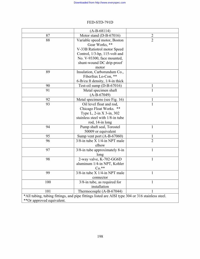
FED-STD-791D
198
(A-B-68114) 87 2 Motor stand (D-B-67016) 88 Va on
V Control, 1/3-hp, 115-volt and
shunt-wound DC drip-proof
2 riable speed motor, BostGear Works, **
-33B Ratiotrol motor Speed
No. V-93300, face mounted,
motor 89 Insulation, Carborundum Co.,
Fiberfrax Lo-Con, ** 6-lb/cu ft density, 1/4-in thick
90 Test-oil 67016) 1 sump (D-B-91 Metal specimen shaft
(A-B-67049) 1
92 Me 6) 1 tal specimens (see Fig. 193 Oil level float and rod,
C
stainless steel with 1/8-in tube
hicago Float Works. **Type L, 2-in X 3-in, 302
rod, 14-in long
1
94 1 Pump shaft seal, Torostel 50009 or equivalent
95 Su 0) mp vent port (A-B-6706 1 96 3 2 /8-in tube X 1/4-in NPT male
elbow 97 3 1 /8-in tube approximately 8-in
long 98
al r 1 2-way valve, K-702-GG6D
uminum 1/4-in NPT, KohleCo.**
99 3 /8-in tube X 1/4-in NPT maleconnector
1
100 3/8-in tube, as required for 1 installation
101 Th 4) 1 ermocouple (A-B-6704*All tubing, tubing fittings, and pipe fitting AISI type 304 or 316 stainless steel. **Or approved equivalent.
s listed are
Downloaded from http://www.everyspec.com
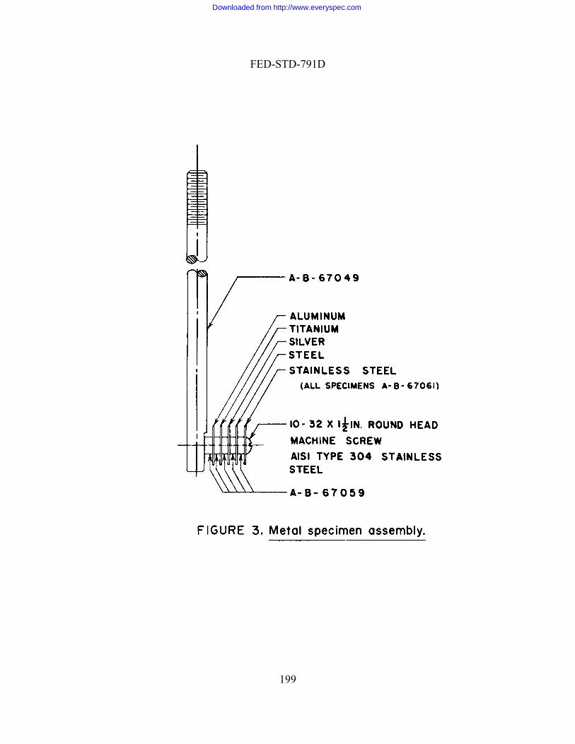
FED-STD-791D
199
Downloaded from http://www.everyspec.com

FED-STD-791D
200
Downloaded from http://www.everyspec.com

FED-STD-791D
201
Downloaded from http://www.everyspec.com

FED-STD-791D
Method 3452.2 September 30 1986 BEARING COMPATIBILITY OF TURBINE OILS 1. SCOPE
1.1 This method is used for determining the bearing compatibility (lacquering, deposits, and corrosion) and stability of MIL-L-17331 turbine lubricating oils when subjected to an endurance test. 2. SUMMARY
2.1 A Journal is operated at specified speed in a babbitt metal bearing lubricated with the test lubricant for 200 h; examining the test bearings and checking the lubricant for changes in viscosity, total acid number, and carbon residue; and computing the work factor from the changes noted. 3. SAMPLE SIZE
3.1 4 L (1 gal) of the oil to be used in each test. (An additional 20 L (5 gal) should be on hand for use in repeating the 3-L (3-qt) flushing procedure as required.) 4. REFERENCES, STANDARDS, AND APPARATUS
4.1 Test equipment illustrated schematically in Figure 1 consist of:
a. Journal (H), shaft material, 4340 steel, 2.750-inch diameter (at bearing surfaces) and hardened to a Rockwell "C" hardness of 40-45, finish ground not to exceed 0.041 µm (16 µin) rms.
b. Bearings (I, J, and K) babbitt metal in split bearing housing (to accommodate journal), size 6.9886-6.9936 cm (2.7514-2.7534 in) (vertical diameter when installed) by 4.60 cm (1-13/16 in) long. (Bearings should be free of scratches or other blemishes). The bearing material over steel backing is 0.013 to 0.025 cm (0.005 to 0.010 in) thick tin base babbitt (SAE 12 babbitt); composition as per SAE standard 1460 is: Sn, 88.25% (minimum); Sb, 7.0-8.0%; Pb, 0.50% (maximum); Cu, 3.0-4.0% (maximum); Fe, 0.08% (maximum); As, 0.10% (maximum); Bi 0.08 (maximum), Zn, 0.005 (maximum); Al, 0.005 (maximum); and others 0.20 (maximum) total. Bearobtained from Mogul-Bower Bearingunder the following part numbers: UppLoading Device (O), hydraulic cylinmaintaining a load of 1520 20 gagearea on the loading bearing (j). (This loN [1000-lb force] on the loading yoke.)
ings of this size and composition may be s, Incorporated, Detroit 13, Michigan er half B-10994, Lower half B-10995.
c. der or other suitable unit capable of kPa (220 3 psig) of projected bearing ading equivalent to approximately 4,400
d. Drive unit (f), to drive journal at a speed of either 1750 or 3500 rpm.
202
Downloaded from http://www.everyspec.com
FED-STD-791D
e. pacity sump, equipped with 3.8 L/min (l Oil system, recirculating, 4-L (l-gal) cagpm) pump and bypass line to sump, to ir late 1 -2.3 L f test lubricant to support and test beari
f. Oil temperat ature sensing device mounted to contact steel shell of upper half of test bearing; this controls
sump heater. Bearing temperature is monitored by spring-loaded thermocouple (M) in contact with steel shell of upper half of test bearing.
oil in sump is recorded from thermocouple (D). High temperature cutoff in the recorder is set for 150°C (300°F).
NOTE 1:
c cu .9 /min (0.5-0.6 gpm) ongs.
ure control. A thermistor (L) or other suitable temper
the
Temperature of oil supply to bearing is monitored from thermocouple (P). High-temperature cutoff switch (C) to sump is to insure against overheating of oil. Temperature of
A suitable cover for the machine is useful for controlling temperatures
sure control. Oil supply to bearings (sum of oil flow to three bearings) is observed at flowrater (T). Oil supply pressure to bearings is
n gage (Q). A minimum oil pressure to bearings of 13.7 gage kPa (2 psig) pressure is insured by low- pressure cutoff switch (S).
during winter months. A wooden box can be used. Thermocouples placed inside and outside the box serve for recording these ambient temperatures.
g. Oil flow rate and pres
observed o
NOTE 2: Detailed drawings of test equipment may be obtained from US Navy Marine Engineering Laboratory, Annapolis, MD.
4.2 The properties of the new lubricating oil will be determined as follows:
a. Viscosity in cSt at 38°C (100°F), 54°C (130°F), and 99°C (210°F), by
by method D 974, ASTM Standards.
5. MAT
5chemical10000, Mhazardouhandlingof each c
5
6. PROC
6 roperties of the new lubricating oil:
method D 445, ASTM Standards. b. Carbon residue, percent, by method D 524, ASTM Standards. c. Total acid number
ERIALS
.1 CAUTION - SOME MATERIALS ARE TOXIC AND HAZARDOUS. The materials listed in this section must be handled carefully. Federal Test Method aterial Handling Safety Precautions, is a reference which lists all toxic and
s materials cited in FTMS 791. The synonyms, life hazard, flammability, and storage precautions, emergency treatment and measures, and spill practices hemical are explained.
.2 Naphtha; aliphatic (TT-N-95), type II [1,4,0].
EDURE
.1 Determine and record the following p
203
Downloaded from http://www.everyspec.com

FED-STD-791D
i
6
a.
b. ings; install the shaft and bearings; use a torque of 115-129 N m (85-95 lb-ft) on bearing cap bolts.
pumpqt) ofadjust oil flow to 1.9-2.3 L/min (0.5-0.6 gpm) (to avoid excess oil pressures).
. Drain all oil from the system and wipe sump clean with lint-less wiping cloths. Remove the oil
NOTE 3.
a. Viscosity b. Carbon residue c. Total ac d
.2 Subject the oil to endurance test as follows:
Drain any old oil remaining in the system; remove sump and wipe clean with lintless wiping cloths and naphtha; remove bearing caps, bearings, and shaft from machine; wipe shaft with lintless wiping cloths and naphtha to remove stains. Spread film of test oil on journal and three sets of new bear
.
c. Flush run. Temporarily install a 10 micrometer filter between the oil sump and inlet. (Filter should be a clean or new filter.) Place approximately 3 L (3 the test oil in sump. Start pump and turn on sump heater, and slowly
Start motor at 1750 rpm. Allow system to operate for 30 min. During the last 10 min apply a load (half that specified for test) to check out the system functioning. Shut down the machine by first unloading the bearing and then stopping the motor drive. Shut off the oil pump and heater
filter from the system and install direct connect from pump inlet to sump.
A single flush run, following the above procedure, will usually provide
pump e to give 1.9-2.3 L/min (0.5-0.6 gpm). using 2 or 3
i Pa (220 psig) of projected bearing area. As the system temperature comes to equilibrium, adjust
perature controller to give a bearing temperature of 138° 0.5°C (280° 1°F) which shall be maintained during the test. Operate the machine
.3 Inspection of bearings at end of 200-hour endurance test. Dismantle all journal rfaces for evidence of deposits, orrosion, wiping, or other changes. Particular reference is to be made to loaded (center)
observation for all bearings.
the used lubricant, as given in paragraph 6.1.
sufficient system cleaning.
d. Test oil. Place 4 L (l gal) of test oil in clean sump and start heater. Start oil and adjust flow with bypass valv
Start motor drive at speed of 3500 rpm and gradually load bearing (m n.) with loading device to yield a load of 1517 gage k
sump tem
under these conditions for a period of 200 h. During this time continuously record bearing temperature, temperature of oil supply to bearing, and temperature of oil in sump. Observe and record (daily) oil flow rate and oil pressure to bearings. Oil flow rate to bearings shall be adjusted during test period to maintain 1.9-2.3 L/min (0.5-0.6 gpm) to bearings.
6 bearings and rinse in naphtha. Observe bearing su
cbearing. Report the
6.4 At the end of the 200 hour endurance test, determine the properties of
204
Downloaded from http://www.everyspec.com

FED-STD-791D
7. CALCULATIONS
scosity, carbon residue, and neutralization number work alues of the test oil. The values shall be computed and reported as follows:
whA B = v
Viscoindivi99°C
where
where: E = neutF = neut
d. 8. REPO
8
this characteristic has not yet been est lis
by more than 0.02 units from the mean.
7.1 Compute the viv
B - 1.00 = value workViscosity a. B)- (A 5
ere= viscosity after endurance test, SUS
iscosity before endurance test, SUS
:
sity work value is determined by averaging the three values obtained from dual calculations based on viscosity data at 38°C (100°F), 54°C (130°F), and (210°F).
:
C-0.80D-0.80 = value work residue Carbon b.
C = carbon residue before endurance test. D = carbon residue after endurance test.
E- 1.01 F- 1.01 = value worknumber acid Total c.
ralization number before endurance test. ralization number after endurance test.
Average the work values obtained and this value is called the work factor.
RTING
.1 Report the three work values and the work factor. 9. PRECISION
9.1 Repeatability. The appearance of the test bearing is of primary importance.
A quantitative rating or comparison scale forab hed. There has, however been no difficulty in reaching conclusions with respect
to excellent, borderline or failing oils. Experience to date indicates that duplicate work factor values can be expected not to differ
205
Downloaded from http://www.everyspec.com

FED-STD-791D
9.2 Reproducibility. This has not been established.
Method Prepared by:
Navy - SH - 1986
206
Downloaded from http://www.everyspec.com
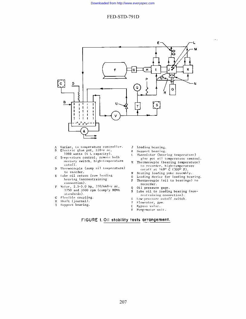
FED-STD-791D
207
Downloaded from http://www.everyspec.com

FED-STD-791D
Method 3456.2
. MATERIALS
5. CAUTION: SOME MATERIALS ARE TOXIC AND HAZARDOUS. The materials references anFederal Test Method 10000, Material Handling Safety Precautions, is a reference whichlists all toxic and hazardous materials cited in FTMS 791. The synonyms, life hazardflammability, handling and storage precautions, emergency treatment and measures, andspill practices of each chemical are explained.
September 30, 1986
CHANNELING CHARACTERISTICS OF LUBRICANTS 1. SCOPE
1.1 This method is used for determining the channeling characteristics of lubricants at low temperature. 2. SUMMARY
2.1 The test consists of storing the sample for 18 h at the temperature required by the specification, cutting a channel in the lubricant with a metal strip, and determining whether the lubricant flows together to cover the bottom of the container within 10 s. 3. SAMPLE SIZE
3.1 Approximately 650 mL of lubricant to be tested. 4. REFERENCES, STANDARDS, AND APPARATUS
4.1 Steel strip, square end (channeling tool), approximately 0.3 � 2 � 23 cm. 4.2 Thermometer, HB Instrument Co., No. 22360, or equivalent. 4.3 Container, flat bottom, approximately 9 cm I.D. by 11 cm high, with 2.5 cm
(minimum) legs, and with cover to support thermometer in center and steel strip at side of container. (See Figure 1).
4.4 Heating bath, 46° to 48°C. 4.5 Cooling bath (non-liquid), capable of maintaining the specified temperature
within 1°C, size sufficient to accommodate container within 3 cm (minimum) clearance on all sides. 5
d standards listed in this section must be handled carefully.
,
208
Downloaded from http://www.everyspec.com
FED-STD-791D
6. PROCEDURE
6.1 Prepare test s
a. Fill container to within 1.3 cm of top with specimen, place in heating bath, and w sample to reach 46°C (5°F). (If a liquid bath is used, adjust bath level to
height of sample.) b
1°C. e thermometer so that the bulb is just below the surface. Insert the
ip into the slit in the cover so that it is in a vertical position in contact
gin ediately after placing the sample in the cooling bath.
ut a ch
it is within 1°C (2°F) of
bc
it as channeling. 7. CAL
NG
the result as channeling or non-channeling.
Method Prepared by:
Army - ME - 1986
etup as follows:
allo
. When sample reaches 46°C, cover container and remove from bath; allow the samples to cool to 22°
c. Position thsteel strwith the wall of the container, with the end resting on the bottom of the container. Immediately place the sample in the cooling bath.
6.2 Store container in cooling bath without interruption for 18 2 h. Be
timing the storage period imm 6.3 At end of storage period, remove container from cooling bath, and within 30 s annel in the sample as follows: c
a. Check sample temperature and make sure that
specified storage temperature. . Without moving steel strip, remove cover and thermometer from container. . Note time to nearest second, and within 5 s scrape the vertically-held steel strip
all the way across bottom of container.
6.4 Within 10 s after cutting the channel (see 6.3), check to determine whether sample has flowed back and completely covered bottom of container. If it has, note it as non-channeling; if not, note
CULATIONS
7.1 This section is not applicable to the test procedure. 8. REPORTI
8.1 Report 9. PRECISION
9.1 Precision data have not been developed for this method.
209
Downloaded from http://www.everyspec.com
FED-STD-791D
210
Downloaded from http://www.everyspec.com
FED-STD-791D
Me d 34 2 Septembe 1986
tho 57.r 30,
4.1.3 ASTM D 1500 - ASTM Color of Petroleum Products. 4.2 Oven, convection, air; controllable to 0.5°C (1°F) in temperature range of
66° and 93°C (150° and 200°F). 4.3 Fluid container (carbonated beverage bottle), 210 mL (7 oz), capable of being
sealed with a cork-lined steel cap. 4.4 Tumbling mechanism (for rotating the fluid container end-over-end at 5 rpm,
inside the oven). 4.5 Brush, short-bristled, stiff (typewriter cleaning brush, or equal).
4.6 Gooch crucible. 4.7 Centrifuse, 1500 rpm. 4.8 Centrifuge tubes, cone-shaped, 100 mL.
HYDROLYTIC STABILITY 1. SCOPE
1.1 This method is used for determining the resistance of a finished oil to reaction when in contact with water. 2. SUMMARY
2.1 The test consists of tumbling under specified conditions, a mixture of the oil and water in a bottle containing a copper strip, and then testing for changes in the oil, water, and copper. 3. SAMPLE SIZE
3.1 Approximately 125 g of the oil to be tested. 4. REFERENCES, STANDARDS, AND APPARATUS
4.1 Standards. 4.1.1 ASTM D 445 - Kinematic Viscosity of Transparent and Opaque Liquids. 4.1.2 ASTM D 974 - Neutralization Number by Color - Indicator Titration.
211
Downloaded from http://www.everyspec.com
FED-STD-791D
4.9 Microscope, 20-diameter magnification. 4.10 Balance, sensitivity 0.2 mg.
. MATERIALS
5.1 CAUTION - SOME MATERIALS ARE TOXIC AND HAZARDOUS. The chemic
fety Precautions, is a reference which lists all toxic and azardous materials cited in FTMS 791. The synonyms, life hazard, flammability,
age precautions, emergency treatment and measures, and spill practices f each chemical are explained.
5.3 Litmus paper.
5.4 Petroleum ether (O-E-751) [1,4,0].
5.5 1,1,1-Trichloroethane (methyl chloroform), stabilized (MIL-T-81533) [2,1,0].
5.6 n-Hexane (technical grade) [1,3,0].
.7 Sodium sulfate, anhydrous (ACS) [u,u,u].
.8 Copper strip (ASTM B 187/B 187M, ASTM B 272), 16 to 22 gage (B&S), 1.3 � 5 6. PRO
.2 Determine the kinematic viscosity of the oil by ASTM D 445.
perature required by the specification.
fluid container (see 4.3).
ish all rfaces of the copper strip with the fine emery paper.
.6 Wash the copper strip in warm petroleum ether or n-hexane, dry, and weigh to with place the strip in the container.
5
al materials listed in this section must be handled carefully. Federal Test Method 10000, Material Handling Sahhandling and storo
5.2 Emery paper, 00 or finer.
5 5.1 cm.
CEDURE
6.1 Determine the acid number of the oil by ASTM D 974. 6 6.3 Heat the oven to the tem 6.4 Weight (to within 0.5 g) 75 g of the sample and 25 g of distilled water and
place in the clean 6.5 Using the filter paper to prevent fingerprints during handling, pol
su 6in 0.2 mg, and immediately
212
Downloaded from http://www.everyspec.com
FED-STD-791D
NOTE 1: Caution. Petroleum ether and n-hexane are both flammable. Use these materials in a well ventilated area. Do not breathe their fumes nor permit
the skin. Keep all flames away from these materials.
6.7 Cap the bottle (with inert seal in place), and mount it in the tumbling mechan
e
as rotated for the required time, filter the liquid contents through a tared Gooch crucible lined with a thin layer of asbestos. Save the filtrate. (The operato loves and a face shield while handling the hot beverage bottle). Rinse the copper strip and beverage bottle with 50 mL of distilled water and 50 her and filter through the Gooch crucible. Save only the water washings and add them to the filtrate.
.10 Process any insolubles that remain in the crucible, as follows:
a Wash the precipitate with 50 mL of distilled water, and add the washings to the
b Wash the precipitate with 50 mL of petroleum ether, and dry the crucible at 66°
c Determine and record the increase in weight of the crucible to within 0.2 mg.
rocess the filtrate as follows:
lean centrifuge tube to within 0.2 mg. b. Transfer the filtrate to the tube, and centrifuge the tube for 15 min at 1500 rpm
c After centrifuging, decant the oil and water layers to suitable separate
a
ashing. b Examine the oil for insolubles, and remove any that still exist, using a
e oil with anhydrous sodium sulfate.
d
e. Determine the kinematic viscosity of the oil by ASTM D 445, and calculate the change from the original viscosity.
them to come in contact with
ism in the oven. 6.8 Allow the mechanism to rotate the container end-over-end at 5 rpm for th
time required by the specification. 6.9 After the container h
r should wear heavy asbestos g
mL of petroleum et
6
. filtrate.
. to 93°C (150° to 200°F).
.
6.11 P
a. Weigh a c
(min.). .
containers.
6.12 Process the oil layer from the centrifuge tube as follows:
. Wash the oil with 25 mL portions of distilled water until the water is neutral tolitmus. Save the water from this w
. combination of filtration, centrifuging, and solvent extraction as necessary.
c. When all insolubles have been removed, dry th
. Determine the acid number of the oil by ASTM D 974, and calculate the changefrom the original acid number.
213
Downloaded from http://www.everyspec.com
FED-STD-791D
f. Determine the color of the oil by ASTM D 1500.
ocess the water layer from the centrifuge tube and the washings as follow
6.13 Pr s:
a. Combine the water from the centrifuge tube with the water from the washings. b of the
STM D 974.
a
um ether (to remove the remaining oil); centrifuge, decant, and dry the tube in the oven.
e
1,1,1-trichloroethane and allow it to dry in air. See note 1 (see 6.6) and note 2.
NOTE 2:
. Determine the acid number of this water (based upon the original weightoil sample) by A
6.14 Determine the weight of any insolubles remaining in the centrifuge tube asfollows:
. Add 50 mL of new test oil to the tube, and centrifuge until the oil is clear. b. Carefully decant the oil, and dry the tube in the oven to remove all traces of
water. c. Again wash the contents of the tube with new test oil, centrifuge until clear, and
decant the oil. d. Wash the residue with petrole
. Determine the increase in weight of the tube to within 0.2 mg.
6.15 Calculate the percentage (by weight) of the insolubles in the oil (see 7.1).
6.16 Remove the copper strip from the fluid container, and process it as follows:
a. Wash the strip with petroleum ether, warm n-hexane, and warm
Caution. 1,1,1-Trichloroethane is toxic. Do not permit it to come in Use only in well ventilated
e change
r square centimeter of total surface. c. Examine the strip under 20X magnification, and record any visible signs of
d. Again wash the strip with petroleum ether, warm n-hexane, and warm
gh to within 0.2 mg.
f.
g. e the loss in weight per square centimeter of total surface.
7. CALC
7.1 Calculate the percentage (by weight) of the insolubles in the oil as follows:
contact with the skin or breathe its fumes. area.
b. Determine the weight change of the strip to within 0.2 mg. Calculate thin weight pe
corrosion.
1,1,1-trichloroethane. While washing, scrub the strip with the short-bristled brush. Allow the strip to air dry, and rewei
e. Repeat this washing until the strip reaches a constant weight. Determine the weight loss of the strip (after brushing) from its originally polished condition. Calculat
ULATIONS
214
Downloaded from http://www.everyspec.com

FED-STD-791D
W = insolubles Percent B) + (A 100
whereA = increase in weight of Gooch crucible. B =
riginal weight of oil sample.
8. RE
8.1 Report the following:
ange of the metal strip before brushing.
mple.
e. change in viscosity of the oil. g. color of the oil after hydrolysis.
9. PR
9.1 Precision data have not been developed for this method.
986
:
increase in weight of centrifuge tube. W = o
PORTING
a. weight ch b. weight change of the metal strip after brushing.
c. change in acid number of the sa d. acid number of the water layer after hydrolysis.
f. weight of insolubles formed during hydrolysis. h. general appearance of the sample after hydrolysis.
ECISION
Method Prepared By:
Army - AR - 1
215
Downloaded from http://www.everyspec.com
FED-STD-791D
Method 3458.1 September 30, 1986
LOW TEMPERATURE STABILITY TEST FOR OIL
ing the tendency of components of finished
oil gels during low-temperature exposure.
efrigerating the sample for 72 h at the temperature quired by specification, and examining it visually for evidence of gelling, separation,
crysta ti 3. SA
e tested. 4. RE E RATUS
4.1 Sample bottle, clear-glass 120 mL, with stopper.
4.2 Cold box, capable of maintaining the specified temperature within "6°C. . MATERIALS
5.1 CAUTION: SOME MATERIALS ARE TOXIC AND HAZARDOUS. The
materials references and standards listed in this section must be handled carefully. Federal Test Method 10000, Material Handling Safety Precautions,lists all toxic and hazardous materials cited in FTMS 791. The synonyms, life hazardflammability, handling and storage precautions, emergency treatment
ed
6.1 Pour sample into bottle, and store bottle for 72 h at the temperature of ("6°C) quired by the specification.
6.2 At the end of 72 h, remove the container from the cold box, and immediately
xamine the sample visually for evidence of gelling, separation, or crystallization.
1. SCOPE
1.1 This method is used for determin blends to be incompatible or to form
2. SUMMARY
2.1 The test consist of rre
lliza on, and clouding.
MPLE SIZE
3.1 Approximately 100 mL of oil to b
FER NCES, STANDARDS, AND APPA
5
is a reference which ,
and measures, and spill practices of each chemical are explain . 6. PROCEDURE
re
e
216
Downloaded from http://www.everyspec.com
FED-STD-791D
7. CALCULATIONS
7.1 This section is not applicable to the test procedure. 8. REPORTING
eport the oil as unstable at the specified temperature, if there is any evidence
f gelling, separation, or crystallization; if there is no such evidence, report the oil as stable.
. PRECISION
9.1 Precision data have not been developed for this method.
Method Prepared by:
Army - ME - 1986
8.1 Ro
Also report the presence of dense cloud, if any, that does not settle out. 9
217
Downloaded from http://www.everyspec.com

FED-STD-791D
Method 3459.1 September 30, 1986
LOW TEMPERATURE STABILITY
1. SCOPE
d at the temperature quired by the specification, agitating it, comparing its turbidity with a standard, and
hecking it for evidence of gelling, crystallization, or solidification. 3. SAMPLE SIZE
3.1 Approximately 240 mL of test fluid.
RATUS
ini e s fied peratures.
25 L, with cork stoppers.
R X ND ZA OU The ust be ha d ca lly der est hod
a reference which lists all toxic and . lity,
nd ll p s
grade), 1:1 solution (by volume) [1,3,0].
f u s fo :
vo
aci nd ke l to sure ,0 L 1 N dium dro e to ke solution
d. Add distilled water to bring total volume to 250 mL.
1.1 This method is used for determining the stability (at low temperature) of finished fluid blends. 2. SUMMARY
2.1 The test consists of storing a sample for the time anrec
4. REFERENCES, STANDARDS, AND APPA
4.1 Cooling apparatus, capable of mainta ng th peci tem 4.2 Sample bottle (2), clear-glass, 0 m
5. MATERIALS
5.1 CAUTION: SOME MATERIALS A E TO IC A HA RD S. chemical materials listed in this section m ndle refu . Fe al T Met10000, Material Handling Safety Precautions, ishazardous materials cited in FTMS 791 The synonyms, life hazard, flammabihandling and storage precautions, emergency treatment and measures, a spi racticeof each chemical are explained.
5.2 Methyl-alcohol-glycerine (technical 5.3 Turbidity standard, prepared within 30 min o se, a llow
a. Pour 25 mL of 0.00322 M barium chloride into a 250-mL lumetric
flask [0,0,2]. b. Add 125 mL of 0.050 N sulfuric d, a sha wel in
complete precipitation [3 ,2]. c. Add approximately 25 m of so hy xid ma
alkaline [3,0,1].
218
Downloaded from http://www.everyspec.com

FED-STD-791D
e. Pour solution into a sample bo , and al it tly with stopper. ttle se tigh
1:
NOTE For red hydraulic liquids, in place of plain distilled water, use distilled water con al Erie Bordeaux B, manufactured by National Aniline Division of Allied Chemicals and Dye Corporation, or equivalent).
6. PRO
6.1 Clean sample bottles, and dry at approximately 100°C for 24 h (min.).
6.2 Pour sample into bottle, and seal bottle tightly with stopper.
6.4 Before end of storage period, cool the methyl-alcohol-glycerine solution to
, shake turbidity standard vigorously for
0 s, and pour into the other sample bottle.
6.6 At the end of the storage period, remove sample from cold storage and shake vigorou
minate frosting (if ecessary), and within one minute of removal from cold storage, compare sample
dity standard.
7. CAL
.1 Report turbidity of sample as less than, more than, or equal to the standard. Also re 9. PRE
Army - NADC - 1986
taining 200 ppm red dye (Nation
CEDURE
6.3 Store sample at the specified temperature for the specified number of hours.
-54°C (-65°F).
6.5 Within 5 min of making comparison1
sly for approximately 10 s. 6.7 Dip specimen into methyl-alcohol-glycerine solution to eli
nvisually with turbi
CULATIONS
7.1 This section is not applicable to the test procedure. 8. REPORTING
8port any evidence of gelling, crystallization, or solidification of the sample.
CISION
9.1 Precision data have not been developed for this method.
Method Prepared by:
219
Downloaded from http://www.everyspec.com
FED-STD-791D
September 30, 1986
STAB . SCOPE
1.1 This method is used for determining the stability of grease in the presence of hot wat 2. SUM
d checking the water for cloudiness or other evidence of emulsification of the sample.
ZE
4. REFERENCES, STANDARDS, AND APPARATUS
- SOME MATERIALS ARE TOXIC AND HAZARDOUS. The hemical materials listed in this section must be handled carefully. Federal Test Method
10000, which lists all toxic and azardous materials cited in FTMS 791. The synonyms, life hazard, flammability,
ge precautions, emergency treatment and measures, and spill practices f each chemical are explained.
eaker, and heat it to entle but active boiling.
6.2 Apply a single lump or globule of the sample to one end
Method 3463.2
ILITY OF GREASE IN HOT WATER (WATER IMMERSION)
1
er.
MARY
2.1 The method consists of immersing the sample in boiling water for 10 min, an
3. SAMPLE SI
3.1 Approximately 5 g of grease to be tested.
4.1 Beaker, 600 mL. 4.2 Stirring rod, glass.
5. MATERIAL
5.1 CAUTION c
Material Handling Safety Precautions, is a reference hhandling and storao
5.2 Distilled water. 6. PROCEDURE
6.1 Place approximately 500 mL of distilled water in the bg
of the stirring rod.
220
Downloaded from http://www.everyspec.com
FED-STD-791D
6.3 Imm ater for 10 min while visually examining erse the sample in the boiling wr, and note the presence of cloudiness, o
7. CALC
This section is not applicable to the test procedure.
8. REP
8.1 Report the presence of cloudiness, or other evidence of emulsification of the
9. PRE
9.1 Precision data have not been developed for this method.
Method Prepared by:
Navy - NADC - 1986
the wate r other evidence of emulsification of the sample.
ULATIONS
7.1
ORTING
sample.
CISION
221
Downloaded from http://www.everyspec.com

FED-STD-791D
STORAGE STABILITY TEST OF FLUIDS AND LUBRICANTS
. SCOPE
1.1 This method is used for determining the storage stability of aircraft turbine raulic fluids. It consists of storing the lubricant in darkness for 12
onths at 23.8° 3°C (75° 5°F), and then inspecting it for changes in homogeneity.
ARY
method duplicates a typical warehouse environment, and it determines if 2 months of static storage at moderate temperatures can affect product homogeneity by
produc tc. The presence or bsence of observed visual changes in homogeneity is a reliable and economical indicator f extended storage stability.
3. SAMPLE SIZE
3.1 Approximately 4 L (1 gal) of the lubricant or fluid to be
. REFERENCES, STANDARDS, AND APPARATUS
ber, constant-temperature 24° d by heavy traffic).
gal), wide-m
ERIALS
ARE TOXIC AND HAZARDOUS. The l materials listed in this section must beMaterial Handling Safety Precautions, us materials cited in FTMS 791. Th and storage precautions, emergency trmical are explained.
inum foil, commercial grade.
ercial grade
Method 3465.1 September 30, 1986
1
lubricants and hydm " "
2. SUMM
2.1 This 1
ing cloudiness, sediment, suspended matter, discoloration, eao
tested. 4
4.1 Cham " 3°C (75° " 5°F), free of vibration (such as cause
4.2 Jar, clear-glass, 3.8 L (1 outh with cap.
5. MAT
5.1 CAUTION: SOME MATERIALSchemica handled carefully. Federal Test Method 10000, is a reference which lists all toxic and hazardo e synonyms, life hazard, flammability, handling eatment measures, and spill practices of each che
5.2 Alum 5.3 Scouring powder, comm . 5.4 Distilled water.
222
Downloaded from http://www.everyspec.com
FED-STD-791D
6. PROCEDURE .1 Clean the jar and cap by scrubbing w
ing an ven at 104°C if desired).
6.2 Line the cap with aluminum foil.
aluminum foil around the jar to exclude all light from the sample.
6.7 At the end of the 12-month period, remove the jar from the chamber and take apper, being careful not to shake or agitate the contents.
ess, sediment,
spended matter, discoloration, or other changes in homogeneity.
. CALCULATIONS
t applicable to the test procedure. 8. REP
the presence of cloudiness, sediment, suspended matter, discoloration, r other changes in homogeneity.
Method Prepared by:
Air Force - SFTL - 1986
6 ith scouring powder and rinsing with tap
water. Complete the rinsing with distilled water, and air dry the jar and cap (uso
6.3 Pour approximately 3.8 L of the sample into the jar, and replace and tighten
the cap.
6.4 Wrap
6.5 Identify the contents of the glass jar (including type of sample, date stored, and any other useful information).
6.6 Store the sample for one year in the storage chamber 24° " 3°C (75° " 5°F).
off the aluminum wr
6.8 Visually examine the sample, and note the presence of cloudinsu
7
7.1 This section is no
ORTING
8.1 Report o
9. PRECISION
9.1 Precision data have not been developed for this method.
223
Downloaded from http://www.everyspec.com

FED-STD-791D
Method 3467.1 September 30 1986
STABILITY OF LUBRICATING GREASE
1. SCO
g grease after a definite storage period at an elevated temperature.
NOT
STORAGE
PE
1.1 This method covers a technique used for measuring the stability of a lubricatin
E: The storage period and temperature at which the grease is to be stored must be given in the specification referencing this test method.
e
after the storage interval and the results compared with data established pr the storage
3. SAMPLE SIZE
standard grease cups (ASTM D 217) with test sample.
. REFERENCES, STANDARDS, AND APPARATUS
4.1 Two standard grease worker cups, grease worker, penetrometer, etc. (ASTM
. MATERIALS
5.1 CAUTION: SOME MATERIALS ARE TOXIC AND HAZARDOUS. The chemic Federal Test Method 0000, Material Handling Safety Precautions, is a reference which lists all toxic and azardous materials cited in FTMS 791. The synonyms, life hazard, flammability,
handling and storage precautions, emergency treatment and measurof each chemical are explained. . PROCEDURE
rease worker cup emove excess insure that the surface of grease is flus
worked penetration, see 6.6.)
2. SUMMARY
2.1 A determination for consistency (unworked and work penetration) is madior to
interval.
3.1 Approximately 1 kg of grease, sufficient to fill two
4
D 217).
4.2 Oven, gravity - convection.
5
al materials listed in this section must be handled carefully. 1h
es, and spill practices
6
6.1 Fill one standard g with the test sample and rgrease to h with the top of the cup. (Sample for un
224
Downloaded from http://www.everyspec.com
FED-STD-791D
6.2 F tity of grease to insure over filling of the ill another cup with sufficient quanmple for worked penetration, see 6.6.)
6.3 Cover the samples with aluminum foil. 6.4 Place the grease filled cups in an oven at the designated test temperature for
storage interval.
samples in a
ONS
whe
C = change in worked penetration
B = penetration after storage
RTING
worked penetration after storage. Report the difference in worked penetration before and after storage as the change in worked
9. PRE
Method Prepared by:
Navy - NADC - 1986
cup. (Sa
the required
6.5 After completion of storage interval, remove the cups from the oven and allow to cool to 25°C (77°F).
6.6 Conduct unworked and worked penetration measurements on the grease ccordance with ASTM D 217.
7. CALCULATI
7.1 Calculate the change in worked penetration after storage as follows:
B- A = C
re:
A = penetration before storage
8. REPO
8.1 Report the unworked and
penetration.
CISION
9.1 Precision data have not been developed for this method.
225
Downloaded from http://www.everyspec.com

FED-STD-791D
September 30, 1986
HOMOGENEITY AND MISCIBILITY OF OILS
ndard reference oils after being submitted to a prescribed cycle of temp rature changes.
ard reference oils, an oil sample is tested to determine if it is and ill remain homogeneous and if it is miscible with the reference oils. A sample oil is
mixed th room tem erature, they are observed for color and evidence of separation. The pour point is determined for each oil. A series of tests are made in cooling baths at 12°C above the expected pour point. The temperature is read at a multiple of 3°C. The test jar is removed and it is tilted to determine if there is movement of the oil. The test jar is
laced in successively lower cooling baths until the oil has ceased to flow. When the oil does not flow when the jar is tilted, hold the jar in a horizontal position for 5 s and observe the oil. If the oil shows any movement under these conditions, place the jar in the temperature. The test is continued under these co ent when the jar is tilted in a horizontal position. The the at this temperature. The samples are thawed. When the loudiness has barely disappeared, the color and evidence of separation is recorded.
s reach room temperature, the thermometers are removed and the mples are heated to 232°C in an oil bath. The sample jars are corked and stored at their
pour po
ed on the Homogeneity and Miscibility Test forms.
E
. REFERENCE, STANDARDS, AND APPARATUS
4.1 Test jar. A test jar of clear glass, cylindrical form, flat bottom, approximately3.0 to 3.5 cm I.D. and 12 to 13 cm in height.
4.2 Thermometers. -80° to +21°C range, conforming to ASTM E 1. 4.3 Cork. To fit the test jar, bored centrally to take the test thermometer.
Method 3470.1
1. SCOPE
1.1 This test determines if an oil is and will remain homogeneous, and if it is miscible with certain sta
e
2. SUMMARY
2.1 Using standw
oroughly with a reference oil and heated. When the oils reach p
p
cooling bath at the next lower nditions until there is no movemrmometer reading is recorded
cAfter the samplesa
ints for 18 to 24 h. When the cloudiness has barely disappeared, after heating, the color and evidence of separation is recorded. The last procedure is repeated. The data is record 3. SAMPLE SIZ
3.1 Approximately 300 mL of oil to be tested. 4
226
Downloaded from http://www.everyspec.com

FED-STD-791D
4.4 Jacket. Glass or metal, water t ht, o , flat bottom, abouig f cylindrical form t 12 .2 gr th e o
jar. 4.5 Disk. C er as the inside of
e jacket.
4.6 Gasket. A ring gasket, about 0.5 cm in thickness, to fit snugly around the outside
4.7 Bath. A cooling bath of a type suitable for obtaining the required
5. MA
6.2 Mix the oil thoroughly and heat to 46°C in a water bath.
6.3 After the oils reach room temperature, observe and record the color and evidenc
il.
artical position in the cooling bath so that not
more than 2.5 cm of the jacket projects out of the cooling medium. b e the test jar
from the jacket carefully and tilt it just enough to ascertain whether there is a hen the
cm in depth, with inside diameter 0.9 to 1 cm eater an th utside diameter of the test
ork of felt, 0.6 cm in thickness of the same diametth
of the test jar and loosely inside the jacket. The purpose of the ring gasket is to prevent the test jar from touching the jacket.
temperatures.
TERIALS
5.1 CAUTION: SOME MATERIALS ARE TOXIC AND HAZARDOUS. The chemical materials listed in this section must be handled carefully. Federal Test Method 10000, Material Handling Safety Precautions, is a reference which lists all toxic and hazardous materials cited in FTMS 791. The synonyms, life hazard, flammability, handling and storage precautions, emergency treatment and measures, and spill practices of each chemical are explained.
5.2 Six reference oils. Information concerning the availability of the reference oil
may be obtained from USA Belvoir Research, Development, and Engineering Center, ATTN: STRBE-VF, Ft. Belvoir, VA 22060-5606. 6. PROCEDURE
6.1 Shake oil sample well and pour into six sample jars to 3.2 cm mark and one sample jar to the 7.5 cm mark. Add a reference oil to each of the six sample jars to the 7.5 cm mark.
e of separation.
6.4 Determine and record the pour point of each o
. Maintain the temperature of the cooling bath at -1° to 2°C. Support the jacket, containing the test jar, firmly in a ve
. Starting at a temperature 12°C above the expected pour point remov
movement of the oil in the test jar. Take a test thermometer reading w
227
Downloaded from http://www.everyspec.com
FED-STD-791D
temperature is 3°C lower then the previous reading. The complete operation of removal and replacement shall require not more than 3 s. If the oil has not ceased to flow when its temperature has reached 10°C, place the test jar in the jacket in a second bath maintained at a temperature of -18° to -15°C. If the oil
the jacket in a third bath maintained at a temperature of -35° to -32°C. For
bath. At no time place the cold test jar
by a stop watch or other accurate timing device, and observe carefully. If hows any movement under these conditions, place the test jar ely in the jacket and repeat a test for flow at the next temperature 3°C
ture, place them in an oil bath after mometers. Heat the bath to 232°C and immediately remove the
move the samples and allow them to thaw. When cloudiness has barely disappe ation.
mogeneity and miscibility of the samples. . CAL
8. RE
8
has not ceased to flow when its temperature has reached -7°C, place the test jar in determinations of very low pour points, additional baths should be maintained with successively lower temperature differentials of about 17°C. In each case transfer the test jar when the temperature of the oil reaches a point of 28°C above the temperature of the new directly in the cooling medium. As soon as the oil in the test jar does not flow when the jar is tilted, hold the test jar in a horizontal position for exactly 5 s, as noted the oil simmediatlower.
c. Continue the test in this manner until a point is reached at which the oil in the test jar shows no movement when the test jar is held in a horizontal position for exactly 5 s. Certain lubricating oils tend to move as a whole and should be very closely observed. Record the reading of the test thermometer at this temperature, corrected for error if necessary.
6.5 Allow the samples to thaw; and when the cloudiness has barely disappeared
observe and record the color and any evidence of separation. 6.6 When the samples reach room tempera
removing the theramples. s
6.7 Cork the samples and store them at their respective pour points for 18 to 24 h. .8 Re6
ared, observe and record the color and any evidence of separ 6.9 Repeat the last operation when the samples reach room temperature. .10 Note the ho6
7
CULATIONS
7.1 This section is not applicable to the test procedure.
RTING PO
.1 Report the data on the homogeneity and miscibility test forms.
228
Downloaded from http://www.everyspec.com
FED-STD-791D
9. PREC
9
ISION
.1 Precision data have not been developed for this method.
Method Prepared by:
Army - ME - 1986
.
229
Downloaded from http://www.everyspec.com
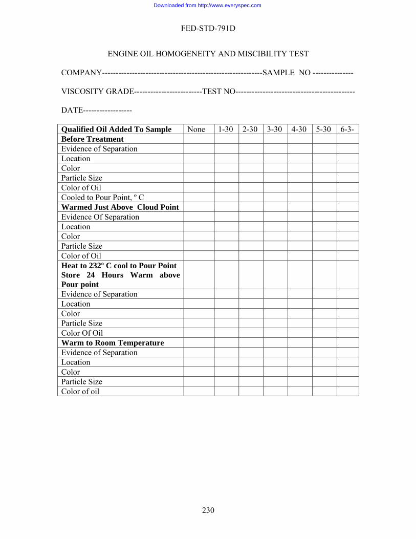
FED-STD-791D
ENGINE OIL HOMOGENEITY AND MISCIBILITY TEST COMP LE NO --------------- VISCOSITY GRADE-------------------------TEST NO-------------------------------------------- DATE------------------ Qualified Oil Added To Sample None 1-30 2-30 3-30 4-30 5-30 6-3-
ANY-----------------------------------------------------------SAMP
Before Treatment Evidence of Separation Location Color Particle Size Color of Oil Cooled to Pour Point, º C Warmed Just Above Cloud Point Evidence Of Separation Location Color Particle Size Color of Oil Heat to 232º C cool to Pour Point Store 24 Hours Warm above Pour point
Evidence of Separation Location Color Particle Size Color Of Oil Warm to Room Temperature Evidence of Separation Lo tion caCo r loPa rticle Size Color of oil
230
Downloaded from http://www.everyspec.com
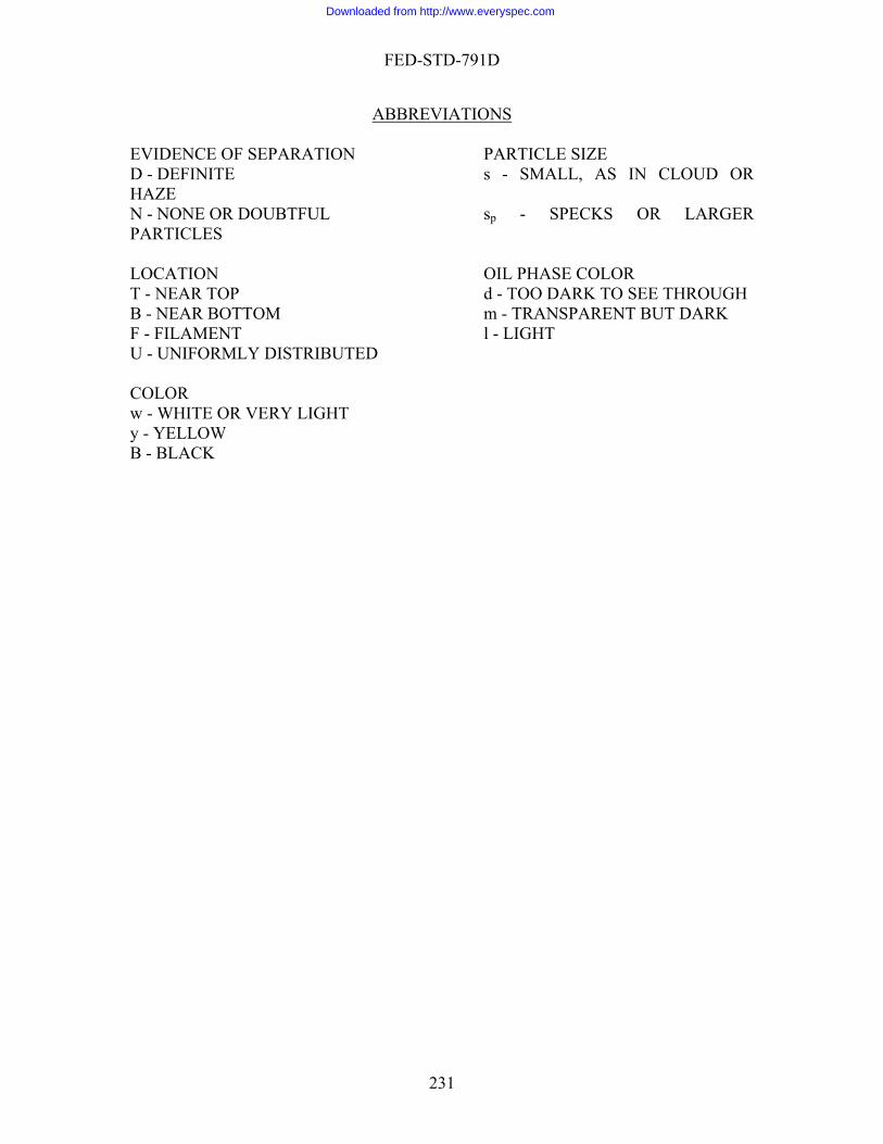
FED-STD-791D
ABBREVIATIONS EVIDENCE OF SEPARATION PARTICLE SIZE D - DEFINITE s - SMALL, AS IN CLOUD OR
- NONE OR DOUBTFUL sp - SPECKS OR LARGER
L E O
d - TOO DARK TO SEE THROUGH m - TRANS AREN UT DARK
ENT l - LIGHT IFORMLY DISTRIBUTED
GHT
HAZE NPARTICLES LOCATION OI PHAS COL R T - NEAR TOP B - NEAR BOTTOM P T BF - FILAMU - UN COLOR w - WHITE OR VERY LIy - YELLOW B - BLACK
231
Downloaded from http://www.everyspec.com
FED-STD-791D
Method 3480.1 September 30, 1986
VOLATILITY OF BLE
for determining the volatility characteristics of a blended
ating the sample for 24 h at 105°C (221°F), and etermining its percentage of weight lost as result of evaporation.
pproximately 10 g of test oil.
. REFERENCES, STANDARDS, AND APPARATUS
° " 0.5
inum foil, 5.7
"0.1 mg.
ERIALS
ARE TOXIC AND HAZARDOUS. The l materials listed in this section must beMaterial Handling Safety Precautions, us materials cited in FTMS 791. Th and storage precautions, emergency tre
chemical are explained.
CEDURE
° " 0.5°C (221° " 1°F
eigh evaporating dish to within 0.2
s to within 0.2 mg. Then place dish into heated oven for 24 h.
NDED OILS 1. SCOPE
1.1 This method is usedoil. 2. SUMMARY
2.1 The test consists of hed 3. SAMPLE SIZE
3.1 A 4
4.1 Oven, gravity-convection, 105 °C (221° " 1°F). 4.2 Evaporating disk, alum cm (2-1/4 in) I.D., 1.6 cm (5/8 in) deep. 4.3 Balance, sensitivity
5. MAT
5.1 CAUTION: SOME MATERIALSchemica handled carefully. Federal Test Method 10000, is a reference which lists all toxic and hazardo e synonyms, life hazard, flammability, handling atment and measures, and spill practices of each
5.2 Test oil.
6. PRO
6.1 Heat oven 105 ). 6.2 W mg. 6.3 Pour sample into evaporating dish, and weigh dish and content
232
Downloaded from http://www.everyspec.com
FED-STD-791D
6.4 At the end of 24 h, rem h, and allow sample to cool to room ove disture.
6.5 Determine the mg (see 7.1).
ATIONS
S = initial weight of sample, in g. mple, in g after the test.
8. REP
g.
9. PRE
Method Prepared By:
tempera
evaporation loss of sample within 0.2 7. CALCUL
7.1 Calculate the evaporation loss of the sample as follows:
100 * SW - S = weightby percent loss, nEvaporatio
where:
W = weight of sa
ORTING
8.1 Report the evaporation loss to the nearest 0.2 m
CISION
9.1 Precision data have not been developed for this method.
Air Force - AFWAL/POSL - 1986
233
Downloaded from http://www.everyspec.com

FED-STD-791D
September 30, 1986
MO ANTS
BY GAS CHROMATOGRAPHY
. SCOPE
1.1 This method covers the determination of monobasic acid components of ester lubricants by gas chromatography. The method is intended for use on any neopentyle polyol ester lubricants where the acid components contain from 4 to 10 carbon atoms. . SUMMARY OF METHOD
alyzed is hydrolyzed with potassium hydroxide,
fol volve the acids. After ether extraction of the cids, the acids are physically separated by gas chromatography and are identified by
o corresponding acids separated under identical operating conditions om a reference standard acid mixture of known composition. The acids are determined
quantit le which is interpreted by omparing peak heights with those obtained on the reference standard mixture of pure
oncentration.
3. SAM
3.1 Approximately 20 g of sample are required for duplicate determination.
4. REFERENCES,STANDARDS, AND APPARATUS
4.1 Chromatograph and Recorder- A chromatoetector and a strip –type recorder may be used provided that the butyric and isovaleric cid components in the standard acid mixture (see 5.21 can be satisfactorily resolved hen the column of 6.1.1 is used and the conditions of 6.1.2 are met. In addition, the
quipment shall have sufficient sensitivity to meet the precision requirements of section .
) long, 0.635 cm 5in) O.D packed with the ixture and in the manner described in section 6.11
Erlenmeyer flask, wide mouth 3.7 cm(1.46 in) I.D 250mL
1.1 Reflusk condenser, spiral, block tin
1.2 Electric hot plate
1.3 Steam bath or flash evaporator
Method 3500.1
NOBASIC ACID COMPONANTS OF SYNTHETIC ESTER LUBRIC
1
2
2.1 The lubricant to be anlowed by hydrochloric acid treatment to e
acomparing them tfr
atively by also using the chromatogram of the sampcacids of known c
PLE SIZE
graph with a thermal conductivity dawe9 Two columns, stainless steel. 183 cm( 6ft (0.2m
234
Downloaded from http://www.everyspec.com

FED-STD-791D
1.4 Crystallizing dish, 9 cm diameter H 5.0 cm deep
1.5 Graduated cylinders, 50 and 100 mL
1.6 Separatory funn
Erlenmeyer flask, narrow mouth, glass stoppered, 300mL
nd complementary to joint of flask described in 4.11
1.10 Syringe, 10-µL capacity, graduated in 0.2µL.
vibrator
thod 10000 , Material Handling Safety Precautions, is a reference which lists all toxic nd hazardous material cited in FTMS 791. The synonyms, life hazard, flammability,
5.2 Potassium hydroxide, reagent grade [3,0,1].
5.3 Ethyl alcohol, 95% [0,3,0].
el , pear shaped ,250 mL
1.7
1.8 Erlenmeyer flask narrow mouth , standard taper joint, 300mL 1.9 Vigreux fractionating column, standard taper joint at lower e
1.11 Analytical balance, 200 g capacity 1.12 Vacuum oven 1.13 Vacuum pump 1.14 Electric stirrer
1.15 Electric
1.16 Filter , size 4.7 cm diameter, 10 µL.
1.17 Stainless filter holder and funnel
5. MATERIALS
5.1 CAUTION: SOME MATERIALS ARE TOXIC AND HAZARDOUS . The materials and standards listed in this section must be handled carefully. Federal test meahandling and storage precautions, emergency treatment and measures and spill practices of each chemical are explained.
5.4 Distilled water
235
Downloaded from http://www.everyspec.com

FED-STD-791D
5.5 Hydrochloric acid, dilute, made by diluting one volume of reagent grade acid, .gr. 1.18 with an equal volume of water [3,0,0].
5.6 Ethyl ether, reagent grade [2,4.1]
.7 Sodium sulfate, anhydrous, reagent grade[u,u.u]
.8 Diethylene glycol adipate polyester [u,u.u]
.9 Gas Chrom P, 60 to 80 mesh, acid-based washed, or equivalent
agent grade, [2,2,0 ].
reagent grade [u,u.u]
gent grade [u,u.u]
ent grade [2,1,0 ].
] 5.19 Pelargonic acid, reagent grade [u,u.u]
5.20 Capric acid, reagent grade [u,u.u]
s give concentrations of the mixed acids in terms of the dicated individual mole percent.
Acid Atom in acid
grams ² Mole percent
sp
5 5 5 5.10 Chloroform ,reagent grade[2,2,0 ]. 5.11 Phosphoric acid, reagent grade, 85% [2,0,0 ]. 5.12 Helium, oil free. 5.13 Butyric acid, re 5.14 Isovaleric acid, 5.15 Valeric acid, rea 5.16 Caproic acid, reag 5.17 Eptylic acid reagent grade [u,u.u] 5.18 Caprylic acid, reagent grade [u,u.u
5.21 Standard acid mixture prepared as follows: 5.22 By means of an analytical balance successively weigh into a 125-mL glass-
Stopperd bottled aa the acids listed in 5.13 through 5.20 in the amounts indicated in the table below. These listed weightin
Number of carbon ¹ Weight in
Butyricovaleric aleric
Caproic
5 5
4.41 5.11 5.11 5.81
10 10 10 10
4 IsV
6
236
Downloaded from http://www.everyspec.com

FED-STD-791D
Heptyli
Pelargonic Capric
9
11.87 17.23
15 15 20
c Caprylic
7 8
6.21 10.82
10
10 ¹ For convenience , these acids hereafter in this method will be referred to by the number of their 5. ² These weights , or some multiole of them are recommended as giving a satisfactory chroma
carbon atoms; e.g., butyric as C4 , isovaleric as is - C
togram of the acids relative to peak heights. 6. PRO
tographic column prepared as follows
col adipate polyester in 150 mL of
chloroform with rapid stirring.
e mix and continue stirring until the acid is comp
and continue stirring for 10 min.
x by flash evaporator or on steam bath.
ting in a vacuum oven for 2 h at 200ºC and 0.1 cm pressure
column using vibrator on column to insure u
he chromatograph and use the programm
ge current of 150mA, and the helium flow at 30.5 L/min. The temperature programming must start immediately after injection.
6.11 Test proc
Hydrolys of lubricant to be a d-Weigh 10 g o lubricant into a wide-mouth Erlenmeyer flask, add lution consisting 8g of potassium e and 15 mL water, followed by 60m l alcohol. Swirl t ix contents.
CEDURE
6.1 Preparation of apparatus
6.2 Column preparation.
6.3 Packing for chroma
6.4 Dissolve 6.0 g of doethylene gly
6.5 Add 1.06 g of phosphoric acid to thletely dispersed. 6.6 Add 23.1 g of Gas Chrom P to the mix 6.7 Remove bulk of chloroform from mi 6.8 Remove remaining chloroform by hea
6.9 Cool and load into chromatographic niform and complete packing. 6.10 Chromatograph- Mount the column in t
ed temperature operation. For this operation, set the controls of the chromatograph for an initial column temperature of140ºC (284 ºF), a final column temperature of 210ºC (410º F), a temperature rate of 8ºC (46º F)/min., a hold time of 20 min at the final temperature, an injection port temperature of 220ºC (428ºF),a detector temperature of 220ºC(428ºF), abridm
edure. 6.12 is nalyze f the
250 –mL a so of hydroxid L ethy o m
237
Downloaded from http://www.everyspec.com

FED-STD-791D
Insert spiral reflux co enser in mouth of flask,connect condenser to cold water line, on hot plate, adjust heat so that contents boil gently and continue refluxing for
to complete dryness on
L water and add washings to funnel. lace funnel in Ice bath, add 50 mL of cold dilute hydrochloric acid (1:1),cool for 10 min
te mixing of contents. Add 50 mL of ethyl ether, shake vigorously for Let phase separate completely and run the
lower (water) phase into a second separatory funnel. Run the upper (ether) layer into a 00 mL glass stoppered Erlenmeyer flask. Add 50 mL of ethyl ether to the second funnel
and re- s above, adding the ether layer to the 300-mL flask epeat the ether extraction of the water layer twice more in individual funnels, collecting
he ethe g of sodium sulfate the ether extract, shake and let stand a few hours or probably overnight. Filter the ether
solutionand funnel a few times with ethyl ether
to ensu complete removal of acids from sodium sulfate.Add 6-10 granules of silicon carbide
until the remaining solution is 20-25 mL stopper flask and retain for essay. Conduct recovery of acids under hood.
.14 Preparation of chromatograms- Using standard acid mixture and the recover e standard acid mixture into the chromatograph, mark for reference on recorder chart paper where
am for peak heights of the acids. If the greatest peak height is dth, the dosage and attenuator settings are
satisfac
ndplace flask16 h.
6.13 Recovery of acid-Transfer contents of flask to crystallizing dish, rinse flask
3 or 4 times with 15 mL water and add washing to dish. Takesteam bath, ¹ , add 15 mL water to dish.and warm to dissolve salts. Transfer solution to separatory funnel, rinse dish 3 or 4 times with 15 mPand swirl to comple min,venting frequently to relieve pressure. 2
3extract the water layer a
.Rt r layers inthe300mL flask. Discard the water layer. Add 35-40 to
through 10-µm filter membrane (using stainless filter and funnel)in to a 300mL Erlenmeyer flask with tapered joint. Rinse filter
re into the flask to avoid superheating, connect to Vigreux column and distill off the
ether in a hot water bath
6ed acids, prepare chromatograms in the following manner: Inject 1 µL of th
recorder pen was located at the time of injection, and complete chromatogram. Examine chromatograpproximately three quarters of the chart wi
tory. If not, adjust dosage and attenuator until the desired peak height is attained
¹A flash
matogram of the standard acid mixture, assign C4 acid to first peak from reference mark on chart, designa 5 through C10 acids in numerical order. Measure in mm the distances from reference mark to each peak and record
evaporator may be used as an alternate for removal of the water and alcohol. In a similar manner inject 1µL of the recovered acid, obtain chromatogram and proceed as above until the peak height of the scan is satisfactory.
Identification and quantitative determination of recovered acids.
6.15 Identification of the acids recovered from the sample- On the chro
te next peak as is -C5 acid, then the successive peaks to -C
each distance against the corresponding acid. These values are designed as the retention times of the acids. On the chromatogram of the recovered acids, measure
238
Downloaded from http://www.everyspec.com
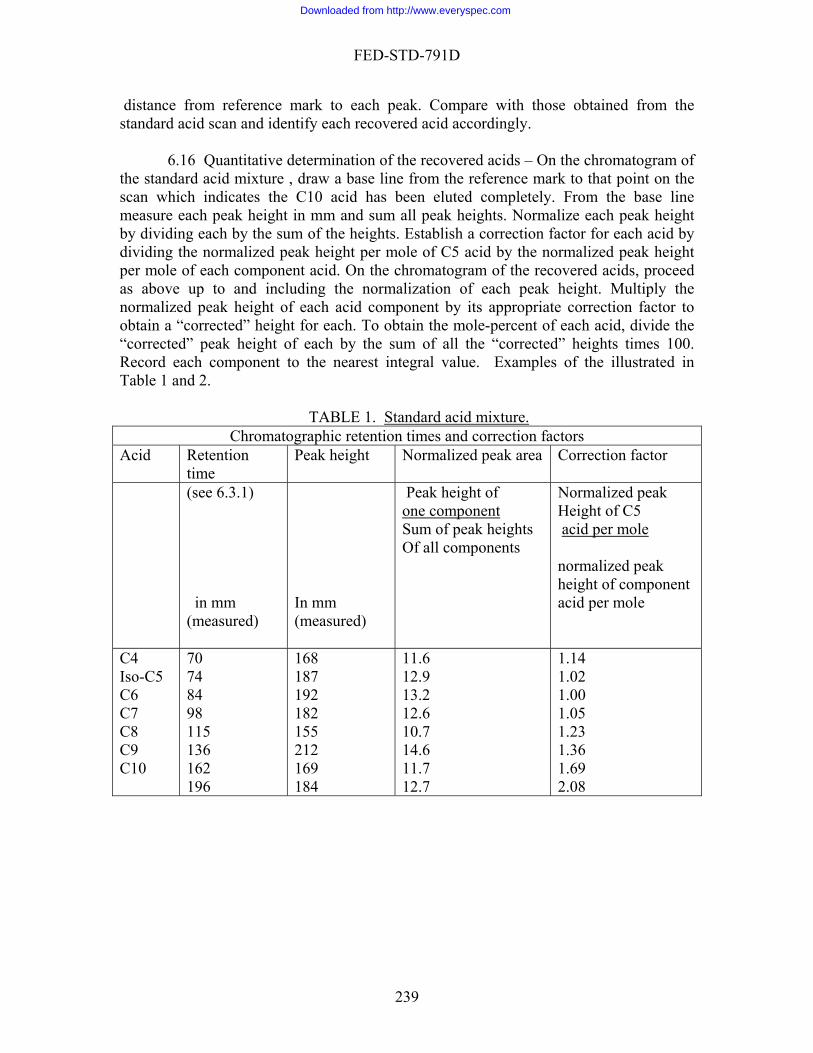
FED-STD-791D
distance from reference mark to each peak. Compare with those obtained from the standard acid scan and identify each recovered acid accordingly.
6.16 Quantitative determination of the recovered acids – On the chromatogram of the standard acid mixture , draw a base line from the reference mark to that point on the scan which indicates the C10 acid has been eluted completely. From the base line measure each peak height in mm and sum all peak heights. Normalize each peak height by dividing each by the sum of the heights. Establish a correction factor for each acid by dividing the normalized peak height per mole of C5 acid by the normalized peak height per mole of each component acid. On the chromatogram of the recovered acids, proceed as above up to and including the normalization of each peak height. Multiply the normalized peak height of each acid component by its appropriate correction factor to obtain a “corrected” height for each. To obtain the mole-percent of each acid, divide the “corrected” peak height of each by the sum of all the “corrected” heights times 100. Record each component to the nearest integral value. Examples of the illustrated in Table 1 and 2.
TABLE 1. Standard acid mixture.
Chromatographic retention times and correction factors Acid Retention
time Peak height Normalized peak area Correction factor
(see 6.3.1)
Peak height of
mponent
in mm (measured)
In mm (measured)
one co Sum of peak heights
Height of C5 acid per mole
Normalized peak
Of all components
normalized peak height of component acid per mole
C4 70 168 11.6 1.14 Iso-C5 C6
10
74 84
162
187 192
169
12.9 13.2
11.7
1.02 1.00
1.36 1.69
C7 98 182 12.6 1.05 C8 C9
115 136
155 212
10.7 14.6
1.23
C196 184 12.7 2.08
239
Downloaded from http://www.everyspec.com

FED-STD-791D
TABLE 2. Unknown acid mixtureChromatographic Identification and mole percent determination
Identified acid
Retention Peak Normalized Correction A Mole time ,mm height
Mm (measured)
peak height factor (see Table 1)
corrected height
percent (rounded)
See 6.3.1 1 2 3 C4
iso C5 C5 C6 C7 C8 C9
71 0 84 98 115 136 162
5 0
165 84 87 21 50
1.2 0
40.0 20.4 21.1 5.1 12.1
1.14 0
1.00 1.05 1.23 1.36 1.69
1.4 0
40.0 21.4 26.0 36.9 20.4
1.2=1 0=0
34.4=34 18.4=18 22.4=22 5.9=6
17.6=18
com all of heights peak of sum ponents
component 1. one of height eak P
heights corrected"" all of sumcomponent of heigh corrected"" times t 100 3.
cor mes 2.
factor rection ti height Peak
7. CALCULATIONS
7.1 This section is not appli
8. REPORTING
R t each component to the neare gral value
RECI N
9.1 Repeatability- Replicate determinations shall not differ another by than le-percent.
9.2 Reproducibility has not been established
Method prepared by: Navy- NAPC-1986
cable to the test procedure
8.1 epor st inte
9. P SIO
from onemore ± mo
240
Downloaded from http://www.everyspec.com
FED-STD-791D
Method 3603.5 30, 1986
SWEL G OF SYNTHETIC S 1. SCOPE
1 This ethod is u d for deter ing the effect of petroleum products on syn c rubber 2. S MARY
ining the volume of three standardized test rubber eets by water displacement, storing them immersed in the sample for 168 h at 70°C, en determining the average change in volume of the sheets.
3. SAMPLE SIZE
3.1 For liquid products: Approximately 300 mL of the liquid to be tested. 3.2 For greases: Approximately 400 g of grease to be tested.
. REFERENCE, STANDARDS, AND APPARATUS
eat-resistant, consisting of:
0 cm long. A graduated t have a pouring
ple: Petri dish, 10 cm O.D. by 5 cm deep with cover
ce, sensitivity "1 mg, suitable for weighing in both air and water.
.4 Spatula (for grease sample). . MATERIALS
hemical materials listed in this section must be handled carefully. Federal Test Method a reference which lists all toxic and
ous materials cited in FTMS 791. The synonyms, life hazard, flammability,
September
LIN RUBBER
1. m se mintheti .
UM
2.1 The test consists of determshth
4
4.1 Container, h
a. For liquid sample: Test tube, 5 cm O.D. by 4cylinder with these dimensions may be used provided it doesn'spout.
b. For grease sam(watch glass).
4.2 Balan 4.3 Oven, gravity-convention, 70° " 1°C (158° " 2°F). 4
5
5.1 CAUTION: SOME MATERIALS ARE TOXIC AND HAZARDOUS. The c10000, Material Handling Safety Precautions, ishazard
241
Downloaded from http://www.everyspec.com
FED-STD-791D
handling and storage precautions, emergency treatment and me res, and spill practiceasu s f c e ic l e a e
5.2 Test sheets (3), rubber standard, type as required by the specification, approximately 2.5 H5. r stock should not be
lder than 6 mo.
5.3 Alcohol, ethyl or methyl, anhydrous [1,3,0].
paper.
led water.
6. PRO
eet to the nearest 1 mg by eighing each sheet in air, then in distilled water at 24° " 3°C, recording the weights,
ifference between the weight in air and the weight in water for each eet (see 7.1).
.2 Fill container with sample, using the following:
a. For liquid sample: Approximately 20 mL of sample for each gram of total
b. For grease sample: Sufficient sample to fill container completely.
6.3 Blot dry each test sheet with filter paper, then immerse sheets completely in samp cuppermo
approxi k). For liquid samples, maintain a ratio of 20 mL of oil to each ram of test sheet. Make up oil must be th
added. re in complete contact with test sheets and close any voids by using a spatula.
.5 At the end of the storage period, cool the sample to 24° " 3°C. Then clean test she
est sheets from sample and wipe them to remove most of the adhering sample.
b
nt of each sheet as specified in 6.1.
o ea h ch m a ar expl in d.
1 H 0.19 cm. Samples of synthetic rubbeo
5.4 Filter
5.5 Distil
CEDURE
6.1 Determine the water displacement of each test shwand computing the dsh
6
weight of test sheets.
le in ontainer. For grease samples, immerse test sheets vertically, with 5 cm edge st, and cover the container.
6.4 Store container in oven at 70° " 1°C (158° " 2°F) for 168 " 0.5 h mately one wee(
g e same temperature as the test fluid when For grease samples, check daily (except weekends), that the samples a
6ets as follows:
a. Remove t
. Dip sheets in alcohol and wipe or blot them dry, using filter paper (or soft cloths). NOTE THE TIME.
6.6 Within 5 min of drying test sheets, redetermine the water displaceme
242
Downloaded from http://www.everyspec.com

FED-STD-791D
7. CALCULATIONS
7.1 Compute the percentage change in volume of each rubber sheet as follows:
where: V = , percent. A = displacement weight at conclusion of test, mg. B = before immersion in sample, mg.
.1 Repeatability. Test results, obtained by one operator at one laboratory, for each te the following:
b. If average is above 5% units: 1% unit.
Method Prepared by:
100 * B)- (A = V B
change in volume
displacement weight 8. REPORTING
8.1 Report the average percent volume change of the three rubber sheets. 9. PRECISION
9st sheet must not vary from the average by more than
a. If average is 0 to 5% units: 0.5% unit.
Navy - NADC - 1986
243
Downloaded from http://www.everyspec.com

FED-STD-791D
Method 3604.2 September 30, 1986
SWELLING OF SYNTHETIC RUBBER BY AIRCRAFT TURBINE LUBRICANTS
or determining the swelling effect of aircraft turbine lub fluids for aircraft turbine engines mu s elastomers used in the ngines. Elastomers are used in seals, o-rings, and related areas. This method is
lubricating fluid-elastomer compatibility problems relative to volume ell.
. SUMMARY
2.1 The volume of three standard test rubber samples is determined by water displac
ge change in olume is determined.
3. SA
3.1 Approximately 350 mL of the lubricant to be tested.
. REFERENCES, STANDARDS AND APPARATUS
4.1 Oven, gravity-convection, 70° 1°C (158° 2°F).
L.
.3 Suspension device, glass or stainlely immersed in specimen in 400-mL beaker).
re (for suspend from balance).
0.1 mg.
ERIALS
materials references and standards listed in this section must be handled carefully.
1. SCOPE
1.1 This method is used fricants on synthetic rubber. Synthetic lubricating st be compatible with materials-of-construction, such a
edesigned to revealsw
2
ement. The rubber samples are immersed in the test lubricant for a specified time (such as 72, 96, or 168 h) at a given temperature. After storage, the averav
MPLE
4
4.2 Beakers (2), borosilicate, 400 m 4 ess-steel (for holding test rubber-sheets
complet aker so that they do not touch each other or the be
4.4 Hooks, stainless-steel wi nding test rubber sheets from suspension
device a 4.5 Balance, sensitivity,
5. MAT
5.1 CAUTION: SOME MATERIALS ARE TOXIC AND HAZARDOUS. The
244
Downloaded from http://www.everyspec.com
FED-STD-791D
Federal Safety Precautions, is a reference which Test Method 10000, Material Handling toxic and hazardous materials cited in ility, handling and storage precautions,
spill pr f each chemical are explained.
5.2 Standard test rubber sheets, type H or FA, fabricated less than one year prior use. Test sheets should conform to the properties listed in U.S. Air Force specification
, Standard Elastomer Stocks. If stored for more than one year, the elastomer ould be retested before use. Storage should be in a dark place at a temperature of less
than 25
5.4 Solvent naphtha, technical grade [1,4,0].
ne, technical grade [2,3,0].
. PROCEDURE
6.1 Clean all glassware as follows:
a. Rinse in toluene, followed by naphtha, and allow to air dry. An alternative dish washer.
b. Soak in glass cleaning solution for 2 h (min.). istilled water. d. Dry in an oven at 100°C (212°F), and store in dust-free location.
.2 Clean suspension device and hooks thoroughly with (toluene and naphtha)
solvent
eat and adjust the oven to maintain the required temperature.
a. Using No. 60 emery cloth, buff both sides of the rubber sheet, using n and then at 90° to that direction. Buff just
enough so that no gloss can be seen on the sheet when viewed by reflected t.
b. Cut three pieces (3.5 � 5 cm) from the sheet.
lists all FTMS 791. The synonyms, life hazard, flammab emergency treatment and measures, and
actices o
tobulletin 539sh
°C (77°F) away from electrical apparatus. 5.3 Cleaning solution, glass (concentrated sulfuric acid [3,0,2] saturated with
potassium or sodium dichromate [1,0,1], technical grade).
5.5 Tolue
5.6 Alcohol, ethyl [0,3,0]. 5.7 Emery cloth No. 60.
6
procedure is to wash in a commercial type
c. Rinse thoroughly with tap water, and then with d
6s, air dry, and store in a dust-free location. 6.3 Preh 6.4 Prepare standard test rubber sheets as follows:
strokes first in one directio
ligh
c. Punch a 0.3-cm (1/8-in) (approximate) hole at the center of the 5-cm side, about 0.6 cm (1/4 in) from the edge.
245
Downloaded from http://www.everyspec.com
FED-STD-791D
d. Mark each piece for future identification by cutting small pieces from one or more corners.
e. Attach wire hooks to each piece.
6.5 Weigh each rubber test sheet (and its hook) in air to the nearest 0.1 mg by suspend
rd the weights.
sample.
spension device, and submerge the sheets in the sam le so that the top edges are no less than 1.3 cm (1/2 in) below the surface. Make certain that the sheets do not touch each other or contact the sides or bottom of the beaker.
6.10 Place the beaker in oven at the required temperature for the specified time.
6.11 At the end of 72 h, remove the beaker from the oven and allow it to cool at room te
alcohol, rubbi rom the surfaces. Caution - w
em to air ry for several minutes.
splacement weight of the rubber sheets after immersion in oil.
7. CALCULATION
7.1 Displacement weight
ing it from the balance by its hook. Record the weights. 6.6 Reweigh (to the nearest 0.1 mg) each sheet while suspended in distilled water
at room temperature, being careful to remove all air bubbles from the sheet and to prevent the sheet from touching the water container. Reco
6.7 Determine (and record) the displacement weight of each piece by subtracting
the weight in water from the weight in air. 6.8 Fill a 400-mL beaker with 350 mL of the 6.9 Attach the rubber sheets to the sup
mperature for 30 5 min.
6.12 Remove the rubber test sheets from the sample and wash them in ethyl ng them gently with the fingers to remove all oil f
ear protective gloves. 6.13 Wipe the rubber pieces dry with soft lint-free cloth, and allow th
d 6.14 Repeat 6.5 to 6.7 to determine the di
water in sheettest of Weight -air in sheettest of Weight
weight ntDisplaceme
246
Downloaded from http://www.everyspec.com
FED-STD-791D
7.2 Calculate the percentage change in volume of each rubber sheet as follows:
100 * B B- A = V
where: V =
8. REP
.1 Report the average percent volume change of the three rubber sheets. 9. PRECISI
not diff
Method prepared by:
change in volume, percent. A = displacement weight at conclusion of test, mg. B = displacement weight before immersion in sample, mg.
ORTING
8
ON
9.1 Repeatability. Results by one operator using one apparatus must not differ by more than 1%.
9.2 Reproducibility. Results from different operators or different apparatus muster by more than 2%.
Navy - NAPC - 1986
247
Downloaded from http://www.everyspec.com
FED-STD-791D
September 30, 1986
MOLYBDENUM DISULFIDE PURITY
1. SCOPE
purity of molybdenum disulfide po
rchloric cid, removing iron with ammonium hydroxide and precipitating solution with lead
ty of MoS2 is determined from the weight of lead molybdate precipitate.
3. SAM
.1 10 g of molybdenum disulfide (MoS2) powder.
RDS, AND APPARATUS
4.1 Hot plate. 4.2 Beakers, borosilicate, 400 and 600 mL. 4.3 Pipet, 50 mL. 4.4 Volumetric flask, 500 mL.
to 6 C (1,020° to 1,110
4.10 Analytical balance.
Method 3710.1
1.1 This method is used for determining thewder.
2. SUMMARY
2.1 This method consists of dissolving the MoS2 in nitric acid and peaacetate. The puri
PLE SIZE
3
4. REFERENCES, STANDA
4.5 Buret, 50 mL. 4.6 Mechanical stirrer. 4.7 Porcelain crucible. 4.8 Muffle furnace capable of maintaining 550° 00° °F). 4.9 Desiccator.
248
Downloaded from http://www.everyspec.com
FED-STD-791D
5. MATERIALS
(Unless otherwise indicated, it is intended that all chemicals shall be of reagent grade and shall conform to the specification stablished by the Committee of Analytical Reagents of the Americ ions are available.)
CAUTION: SOME MATERIALS ARE TOXIC AND HAZARDOUS. The hemical materials listed in this section must be handled carefully. Federal Test Method
10000,s materials cited in FTMS 791. The synonyms, life hazard, flammability,
andling and storage precautions, emergency treatment and measures, and spill practices are explained.
loric acid, conc. (reagent grade) [3,0,0].
,0,u].
0.1 g methyl orange crystals
eagent grade) in 100 mL of distilled water [u,u,u].
.7 Ammonium acetate solution. Dissolve 605 g of ammonium acetate (reagent grade) er to 2 L [u,0,u].
cid (reagent grade) [2,2,1].
olve 20 g of lead acetate, Pb(CH3COO)2 � 3H2O (reagent grade) in distilled water, add 20 mL of glacial acetic acid (reagent grade) and dilute with distilled water to 1 L [u,u,u].
.
tor. Dissolve 0.05 g tannic acid (reagent grade) [0,1,0] in 48 mL of distilled water and add 2 mL of glacial acetic acid (reagent grade) [2,2,1].
.12 Ammonium nitrate solution. Dissolve 30 g of ammonium nitrate (reagent grade) and dilute with additional distilled water to 1 L [0,1,3]. 6. PRO
6.1 Weigh a moisture- and oil-free sample (See Note l) of powder, 2.6 to 2.8 g, n an analytical balance to the nearest 0.1 mg and transfer the sample to a 400-mL
beaker.
s ean Chemical Society, where such specificat
5.1
c Material Handling Safety Precautions, is a reference which lists all toxic and
hazardouhof each chemical
5.2 Potassium chlorate (reagent grade) [1,0,2]. 5.3 Nitric acid, conc. (reagent grade) [2,0,0].
5.4 Hydroch
5.5 Ammonium hydroxide, conc. (reagent grade) [u
5.6 Methyl orange indicator solution. Dissolve(r
5in distilled water and dilute with distilled wat 5.8 Glacial acetic a 5.9 Lead acetate solution. Diss
5.10 Tannic acid [0,1,0] 5.11 Tannic acid indica
5in distilled water
CEDURE
o
249
Downloaded from http://www.everyspec.com
FED-STD-791D
NOTE 1. Moisture may be removed by heating MoS2 powder in a drying oven at 05°C for 1 h.Oil may be removed by extraction with acetone and petroleum ether.
l and while stirring dilute with distilled water to 50 5 mL.
.5 To this solution add 40 mL of concentrated ammonium hydroxide (this will precipi lter through Whatman No. 40 (or equivalent) paper. Paper pulp may be added to aid filtration. Collect filtrate in 600-mL beaker
ortions of hot distilled water, collecting the filtrate in the 600-mL beaker containing first filtrate. Retain combin
.7 Transfer filter paper with residue to clean 400-mL beaker, add 10 mL of hydroc
.8 To this solution add 40 mL of distilled water and while stirring add 40 mL of concen a boil. While the solution is hot, filter through Whatman No. 40 (or equivalent) paper, and collect the filtrate in the 600-mL bea
d residue (see Note 2) and retain combined filtrate.
NOT
1
6.2 Add l mL of distilled water to the sample and moisten particles of MoS2. Add with caution 30 mL of a saturated solution of potassium chlorate in nitric acid.
6.3 After vigorous action ceases, place the beaker on a hot plate and digest the sample slowly until the solution becomes pale yellow or almost white. Add 0.5 g of potassium chlorate to the solution and evaporate it to dryness.
6.4 Add 15 mL of conc. HCl, and boil solution until all brown fumes are
expelled. Allow solution to coo
6tate iron). Heat to boiling and while hot fi
and retain. 6.6 Wash residue on filter paper 5 times with 10-mL p
ed filtrate. 6hloric acid. Stir until filter paper is pulped. 6trated ammonium hydroxide. Bring solution to
ker containing the previous filtrate. Wash residue on filter paper with 25-mL portions of hot distilled water 8 times, collecting filtrate in the 600-mL beaker with the combined filtrate.
6.9 Discard filter paper an
E 2. The filter paper and residue can be used to determine percent total insoluble matter. Place filter paper and residue in a previously ignited and weighed porcelain crucible, carefully burn off filter paper and then place
nition to constant weight. Calculate percent total insoluble matter (see 7.1).
6.10 Transfer the combined filtrate from the 600-mL beaker to a 500-mL volume
in muffle furnace at 600°C for l h. Remove crucible and place in desiccator for l h, when cooled remove and weigh. Repeat ig
tric flask, dilute with distilled water to 500 mL.
250
Downloaded from http://www.everyspec.com
FED-STD-791D
6.11 Using a 50-mL pipet, pipet a 50-mL aliquot into a 400-mL beaker, add 2 drops of methyl orange indicator and neutralize the excess ammonium hydroxide in the
te aliquot with drops of concentrated hydrochloric acid. Neutralization will be comple
.12 Add 30 mL of ammonium acetate to the solution and 10 mL of glacial acetic acid. H
cetate solution (31 to 33 mL/0.26 to 0.28 g of sample) in aliquot respectively, (see Note 3), to the sample solution from a
ion.
NOT
filtrate at the first sign of pink or red color in the solution. 6eat solution to near boiling. 6.13 Add a previously calculated amount of lead a
buret, dropwise at the rate of 30 mL in 2 min. While stirring the solution mechanically add an excess of 3 mL of lead acetate and stir for 5 min after complete addit
E 3. For an accurate check on the quantity of lead acetate solution required, the tannic acid solution can be used as an outside indicator. The end point is reached when a drop of the neutralized aliquot solution added to 0.1 mL of the tannic acid indicator solution on a spot plate fails to give a brown coloration.
least l hour and allow the precipitated lead molybdate to settle completely.
gh a Whatman No. 42 (or equivalent) paper containing a small amount of paper pulp. Transfer the precipitate to the filter paper and wa
for l h.
ool room temperature. Weigh crucible. Repeat ignitions to constant weight. Calculate the
we t 7. CALCULA
7.1 Th
6.14 Place sample solution on a hot plate and heat until near boiling and hold at this point for at
6.15 Decant the bulk of the solution throu
sh 4 times with 50-mL portions of hot ammonium nitrate solution. The filtrate can be discarded.
6.16 Place filter paper with residue in a previously cleaned, ignited, cooled and
weighed porcelain crucible. Ignite carefully in a muffle furnace at 550° to 600°C (1,020° to 1,110°F)
6.17 Remove crucible and place in desiccator for 30 to 60 min and allow to c
toight percen MoS2 (see 7.2).
TIONS
e percent total insoluble matter may be calculated as follows:
251
Downloaded from http://www.everyspec.com

FED-STD-791D
100 * wc =matter insoluble total Percent
w = weight of moisture- and oil-free sample
where: c = increasew = weight and oil-free sample
eport the percent total insoluble matter and percent MoS2.
where: c = weight of residue in crucible
7.2 The percent MoS2 is calculated using the following equation:
435.9 * wc = MoS Percent 2
in weight of crucible of moisture-
8. REPORTING
.1 R8
9. PRECISION
9.1 Precision data have not been developed for this method
Method Prepared by:
Navy - NADC - 1986
252
Downloaded from http://www.everyspec.com

FED-STD-791D
Method 3720.2 September 30, 1986
MOLYBDENUM DISULFIDE CONTENT OF LUBRICATING GREASE
1.
1.1 This method is used to determine the molybdenum disulfide content of lubrica es that contain on-soa
2. SUMMARY
2.1 This method consists of dissolving the base oil and soap thickener in a ixture of oleic acid and benzene. The MoS2 is removed by filtration and MoS2 content
e by weighing the MoS2. 3.
lubricating grease to be tested.
. REF
cator.
4.3 Filter pump (aspirator). 4.4 Flask, filtering heavy wall. 4.5 Gooch crucible and suitable holder. 4.6 Oven capable of 100°C. 4.7 Steam bath.
. MATERIALS
5.1 CAUTION: SOME MATERIALS ARE TOXIC AND HAZARDOUS. The ust be ha d ca lly der est hod
a reference which lists all toxic and . lity,
nd ll p s
SCOPE
ting greases. This method does not apply to lubricating greasp thickeners. n
md termined
SAMPLE SIZE
3.1 5 g of 4 ERENCES, STANDARDS, AND APPARATUS
4.1 Desic 4.2 Erlenmeyer flask, 125 mL.
5
chemical materials listed in this section m ndle refu . Fe al T Met10000, Material Handling Safety Precautions, ishazardous materials cited in FTMS 791 The synonyms, life hazard, flammabihandling and storage precautions, emergency treatment and measures, a spi ractice of each chemical are explained.
253
Downloaded from http://www.everyspec.com
FED-STD-791D
5.2 n-Hexane, ACS grade [1,3,0]. 5.3 Oleic acid, USP grade [0,1,0].
URE
3 to 5 g of the grease to be tested to the nearest mg and distribute as a thin layer in a 125 mL Erlenmeyer flask prior to adding 90 mL of a
-50 mixture by volume of n-hexane and oleic acid. (See Note 1). b. Warm the flask for approximately 1/2 h on a steam bath with occasional
the flask through a previously prepared and weighed (to the nearest mg) Gooch crucible. Wash the flask and crucible with
ximately 10 mL of a 50-50 mixture by volume of oleic acid and n-hexane, followed by three washings with petroleum ether. (See Note 1.)
NOTE 1:
5.4 Petroleum ether (O-E-751) [1,4,0].
6. PROCED
6.1 Perform the test as follows:
a. Weigh
50
agitation until all lumps have disappeared and the molybdenum disulfide is dispersed.
c. Filter the contents of
appro
Caution. n-Hexane and petroleum ether are both toxic and flammable. Do come in contact with the skin.
Keep flames away from the n-hexane and petroleum ether.
d. Dry the crucible and contents at 100°C for 1/2 h, cool in a desiccator to igh. (See Note 2).
NOT
not breath their fumes nor allow them to
room temperature and we
E 2: The purity of MoS 2 powder may be determined in accordance with test method No. 3710 or by means of spectrochemical analysis.
7. CALCULATIONS
.1 Calculate the percentage of molybdenum disulfide as follows:
. REP
e [0,1,0].
7
100 * sampleof weight
crucible of weight in Increase = matter) insoluble (as disulfide molybdenum centPer
8 ORTING
8.1 Report the percent molybdenum disulfide as insoluble matter.
8.2 n-Hexane, ACS grade [1,3,0]. 8.3 Oleic acid, USP grad
254
Downloaded from http://www.everyspec.com
FED-STD-791D
8.4 Petroleum ether (O-E-751) [1,4,0]. 9. PRO
gh 3 to 5 g of the grease to be tested to the nearest mg and distribute
as a thin layer in a 125 mL Erlenmeyer flask prior to adding 90 mL of a of n-hexane and oleic acid. (See Note 1).
b. Warm the flask for approximately 1/2 h on a steam bath with occasional
c. ighed
owed by three washings with petroleum ether. (See Note 1.)
NOTE 1:
CEDURE
9.1 Perform the test as follows:
a. Wei
50-50 mixture by volume
agitation until all lumps have disappeared and the molybdenum disulfide is dispersed. Filter the contents of the flask through a previously prepared and we(to the nearest mg) Gooch crucible. Wash the flask and crucible with approximately 10 mL of a 50-50 mixture by volume of oleic acid and n-hexane, foll
NOTE 2:
Caution. n-Hexane and petroleum ether are both toxic and flammable. Do not breath their fumes nor allow them to come in contact with the skin. Keep flames away from the n-hexane and petroleum ether.
d. Dry the crucible and contents at 100°C for 1/2 h, cool in a desiccator to
room temperature and weigh. (See Note 2).
The purity of MoS2 powder may be determined in accordance with test
0. CALCULATIONS
10.1 Ca
11. REPORTING
11.1 Report the percent molybdenum disulfide as insoluble matter.
Method Prepared by: Navy - NADC - 1986
method No. 3710 or by means of spectrochemical analysis.
1
lculate the percentage of molybdenum disulfide as follows:
100 * sampleof weight
crucible of weight in Increase = matter) insoluble (as disulfide molybdenum Percent
12. PRECISION
12.1 Precision data have not been developed for this method.
255
Downloaded from http://www.everyspec.com
FED-STD-791D
Method 3722.2 September 30, 1986
MOLYBDENUM DISULFIDE CONTENT OF NON-SOAP BRICATING GREASES
1. SCOPE
1.1 Th kened greas 2. SUMMARY
2.1 Thn-hexane and precipitation to
3.
3.1 Ap
4. RE E
4.1 Desiccator.
4.2 Ov
ce capable of 760°C.
4.5 Steam bath. 4.6 Soxhlet extraction apparatus with 250-mL flask.
(2), 600 mL.
ls (2).
4.11 Policeman, rubber.
THICKENED LU
is method is used to determine the MoS2 content of non-soap thices.
e test consists essentially of extracting the base oil from the grease with determining the molybdenum disulfide content of the remaining solids by sulfate with barium chloride.
SAMPLE SIZE
proximately 5 g of grease to be tested.
FER NCES, STANDARDS, AND APPARATUS
en capable of 100°C.
4.3 Muffle furna
4.4 Hotplate.
4.7 Beakers 4.8 Crucibles (2), 50 mL. 4.9 Funne 4.10 Burner, Meker (or equivalent).
256
Downloaded from http://www.everyspec.com

FED-STD-791D
5. MATERIALS
5.1 CAUTION: SOME MATERIALS ARE TOXIC AND HAZARDOUS. The chemical mate Test Method 10000, Material Hand ch lists all toxic and azardous materials cited in FTMS 791. The synonyms, life hazard, flammability,
mergency treatment and measures, and spill practices f each chemical are explained.
2 Hexane, normal, ACS [1,3,0].
ction thimble (double thickness 3.3 � 8.0 cm).
quivalent).
s mixture - 2 parts of calcined ("light") magnesia thoroughly mixed ith one part of sodium carbonate [u,u,u].
5.7 Bromine water, saturated [4,0,0].
5.8 Barium chloride, 10% [0,0,2].
.9 Sodium carbonate, CP [u,u,u].
.10 Potassium carbonate, CP [u,u,u].
6. PROCEDURE
.1 Determine the solids content of the grease as follows:
a. Dry an extraction thimble (3.3 � 8.0 cm) at 100°C, cool in a desiccator g. Dry thimble to constant
weight. Weigh approximately 5 g of the grease to be tested into the
b. Place 200 mL of n-hexane in the flask, place the thimble containing the e Soxhlet extraction tube, and assemble the apparatus
as shown in Figure 1. of a hotplate bring the hexane to boiling and reflux until the
base oil has been completely extracted from the grease (see Note 1). ay be determined by sampling small (2 mL)
quantities of hexane from the extraction tube and evaporating on a clean An oily film will remain if oil is contained in the
sample.
rials listed in this section must be handled carefully. Federalling Safety Precautions, is a reference whi
hhandling and storage precautions, eo
5.
5.3 Extra
5.4 Filter paper (Whatman No. l or equivalent). 5.5 Filter paper (Whatman No. 40 or e
5.6 Eschka'w
5 5
6
and weigh to the 100° C nearest tenth of a m
extraction thimble.
grease sample in th
c. By means
Complete removal of the oil m
evaporating dish.
257
Downloaded from http://www.everyspec.com

FED-STD-791D
NOTE 1. Caution. n-Hexane is both toxic and extremely flammable. Use only in a well ventilated area. Do not breathe its fumes nor allow it to come in
eight of the solids in the grease. Calculate the percent solids (see 7.1).
.2 Determine percent molybdenum disulfide in the grease as follows:
a Ignite a clean crucible (50 mL) in the blue oxidizing flame of a Meker burner.
imately 2 g of Eschka's mixture and weigh to the nearest 0.1 mg.
b 1 d) and reweigh to the nearest 0.1 mg (throughly mix by stirring sample using a wire rod).
c
d A blank determination using 4 g of Eschka's mixture is conducted in a separate
e Place both crucibles in a cold muffle furnace and slowly raise the temperature to f 760°C for 2 h. Remove the crucibles from
the muffle furnace and allow to cool. f. ible into separate 600-mL beakers and place
the crucibles in a horizontal position in the beakers. Cover the crucibles with
g Place on heated steam bath for 30 min. Remove and rinse each crucible so that ater is deposited in the beakers.
h. Pass the contents of beaker through filter paper (Whatman No. l or equal) and residue and paper.
i. Add 10 mL of saturated bromine water to the filtrates. Heat gradually to
j. Cool beake
k. While boiling, add at a very slow rate 10 mL of 10% solution of barium
l. Pass tbarium the surfaces of the beakers by means of a rubber
m. Cleancarboweigh
n. Fold to. Place the crucibles in a cold muffle furnace and heat gradually to a temperature
of 400°C. Hold at 400°C until the filter papers are thoroughly charred. Slowly
contact with the skin. Keep all flames away from the Hexane.
d. Remove the thimble from the extraction tube and dry in an oven at 100°C. Allow to cool in a desiccator. After cooling, remove and weigh to constant weight. Subtract the weight of the thimble from the latter weight to determine the w
6
. Cool in a desiccator. Remove and add approx
. Add approximately 0.1 g of the grease solids (6.
. Place a layer 0.6 cm (0.25 in) of Eschka's mixture on the sample from 6.2 b. Do not mix.
. crucible.
. 760°C. Maintain a temperature o
Remove the contents of each cruc
distilled water. .
the rinse w
rinse the residue 2 or 3 times with distilled water. Discard
boiling. Continue to boil until the volume is reduced to 200 mL. the solution and add 5 mL of concentrated hydrochloric acid to each r and boil until colorless.
chloride. Heat on a steam bath for at least 3 h, and allow to stand for 24 h. he solutions through filter paper (Whatman No. 40 or equal). Remove all sulfate adhering to
policeman. Wash the precipitates and discard the filtrates. the crucibles by fusing 50-50 mixture of sodium and potassium nates. Do not use potassium bisulfate. Dry and cool the crucibles and to the nearest 0.1 mg. he filter paper and precipitates, and place in the clean weighed crucibles.
258
Downloaded from http://www.everyspec.com

FED-STD-791D
raise the temperature to 760° C and maintain at this temperature until there is no r any carbon present. This will require approximately l h at 760°C. The
sulfate should be pure white. longebarium
p. Allow the crucibles to cool and determine the weight of barium sulfate in each
and req. Calcu r. Calcula S2 in the grease (see 7.3).
NOTE 2:
one. Subtract the weight of barium sulfate in the blank from that of the sample cord the difference as the weight of barium sulfate. (See note 2). late the percent MoS2 in the grease solids (see 7.2).
te the percent Mo
A spectrochemical analysis may be conducted to determine purity of
7. CALC
7
where WlW2 =
wh M M
7
MoS2.
ULATIONS
.1 Calculate the percent solids as follows:
100 * w
= solidsPercent1
2 w
:
= weight of solids in sample weight of sample
7.2 Calculate the percent MoS2 in the grease solids as follows:
100 * M * 0.343 = solidsgrease in MoS Percent 22
M
ere:
= weight of solids from grease sample 2 = weight of barium sulfate
.3 Calculate the percent MoS2 in the grease as follows:
7.2) (see solidsgrease in MoS percent* 7.1) (see solidpercent = MoS Percent 22
259
Downloaded from http://www.everyspec.com

FED-STD-791D
8. REPO
8.1 Report the percent solids, percent MoS2 in grease solids, and percent MoS2. 9. PREC
.
Method Prepared by
Navy - NADC – 1986
RTING
ISION
9.1 Precision data have not been developed for this method
260
Downloaded from http://www.everyspec.com
FED-STD-791D
Method 3816.1 September 30, 1986
FILM THICKNESS OF DRY SOLID FILM LUBRICANTS
. SCOPE
1.1 This method provides a means for measuring the film thickness of dry film bricants.
. U A
2.1 The thicknspecified areas using a template and precision micrometer. The difference in readings
nt
in xture of sp ble sist .
RATUS
6 He atta ent (Binks
f suri o th are .00 m (0.0001
6 in) with four 0.95-cm -in) es c red (5/8 in th .2- side
(see Figure 1).
5. MATERIALS
5.1 CAUTION: SOME MATERIALS ARE TOXIC AND HAZARDOUS. Thechemical materials listed in this section must be handled carefully. Federal Test Method10000, Material Handling Safety Precautions, is a reference which lists all toxic and hazardous materials cited in FTMS 791. The synonyms, life hazard, flammability,handling and storage precautions, emergency treatment and measures, and spill practicesof each chemical are explained.
5.2 Aluminum alloy test panel conforming to ASTM B 209, 7.6 � 15.2 � 0.051
cm (3 � 6 � 0.020 in) thick, anodized in accordance with MIL-A-8625, Type 1. 5.3. 1,1,1-Trichloroethane (MIL-T-81533) [2,1,0].
1
lu
2 S MM RY
ess of a coated and uncoated aluminum panel is measured in four
represents the film thickness of the lubrica . 3. SAMPLE SIZE
3.1 240 mL (8 oz) of solid-film lubricant a mi raya con ency 4. REFERENCES, STANDARDS, AND APPA
4.1 Binks Spray Gun, Model 18, with a 6 SD ad chmManufacturing Company, Chicago, Illinois or equal).
4.2 Vernier micrometer capable o mea ng t e ne st 0 25 m
in), or an equivalent measuring device. 4.3 Template - 7.6 � 15.2 cm (3 � (3/8 hol ente
3.8 cm (1-1/2 in) in from the 7.6-cm side and 1.6 cm in) from e 15 cm
261
Downloaded from http://www.everyspec.com
FED-STD-791D
6. PROCEDURE
a. Degrease the test panels in 1,1,1-trichloroethane.
b. Place template in position on the uncoated panel, trace the circumferences of the openings in the template on to the test panel.
micrometer having 0.0025-mm (0.0001-in) graduations. Note the thickness measurement for each circled area.
6.2 Perform the test as follows:
pplication shall be conducted in a well ventilated area or hood, where no flames or ignition sources are present. Care
aken to insure that the panel has a uniform coating of solid lubricant. b. Air dry, temperature 25° 2°C (77° 3°F) test panel for ten minutes between
n minutes, then cure the film in accordance with specification requirements.
in) between spray gun and test panel while spraying.
dfter curing.
f. Remeasure the thickness of the test panel at the same positions. g
7. CALCULATIONS
whe
6.1 Prepare test panel as follows:
c. Measure the thickness of the test panels at the circled areas with a
a. Apply two coats of dry solid film lubricant by spraying the solid lubricant to the unmarked side of the test panel. A
should be t
coats. After the final application, allow coated test panel to air dry for fiftee
c. Maintain a distance of approximately 30 cm (12
. Use an air pressure of 275 35 gage kPa (40 5 psig) e. Allow test panel to reach room temperature a
. Duplicate tests shall be conducted.
7.1 Calculate the film thickness as follows:
B-A=F
re:
F = film thickness A = thickness of the coated panel B = thickness of the uncoated panel
8. REPORTING
8.1 The average of four readings shall be reported as the film thickness of the dry solid film lubricant.
262
Downloaded from http://www.everyspec.com

FED-STD-791D
9. PRECISION
9.1 Precision data have not been developed for this method.
Method prepared by:
Navy - NADC - 1986
263
Downloaded from http://www.everyspec.com
FED-STD-791D
Method 4001.3 September 30, 1986
CORROSION PROTECTION COATING: SALT-SPRAY (FOG) TEST 1. SCOPE
1.1 This method is intended for the determination of throvided by fluid, semi-solid, and solid coatings.
. SUMMARY
2.1 The test consists of exposing test panels to either 5 or 20% salt (NaCl) spray s stated in the product specification. When the salt concentration is not stated in the roduct specification, the 5% salt solution shall be used.
. SAMPLE SIZE
3.1 Approximately 500 mL of the mater 4. REFERENCES, STANDARDS, AND APPARATUS
4.1 Exposure chamber, with racks for supporting test panels, and with suitableheaters and controls.
NOTE 1:
e corrosion protection p 2
ap 3
ial to be tested.
The chamber and all accessories shall be made of material which will notaffect the corrosiveness of the fog (such as glass, hard rubber, plastic, orwood other than plywood.) In addition, all parts which come in contactwith the test panels shall be of materials that will not result in acceleratedlocal attack associated with dissimilar metal crevices. The chamber andaccessories shall be so constructed and arranged that there is no directimpinging of the spray or dripping of the condensate on the test panels, sothat the spray circulates freely about all panels to the same degree and sothat no liquid which has come in contact with the panels returns to the saltsolution reservoir. The chamber shall be properly vented. Satisfactorycabinets may be obtained from the Industrial Filter and Pump Mfg. Co.,Chicago, Illinois.
4.2 Atomizers, including suitable nozzles and compressed air supply (for
producing a finely divided, wet, dense fog).
Humidifier, atomizer-air (for warmrelative humidity at the nozzle of at least 85%).
4.3 ing and humidifying the air to produce a
264
Downloaded from http://www.everyspec.com

FED-STD-791D
NOTE 2: A high humidity insures against n.
er containing heated water. The temperaturer. The permissible temperature increases
decreas should ot exceed a value above which an excess of moisture is introduced into the chamber (for
°C [110°F] at an air pressure of 82 gage kPa [12 psig]), or a value which akes it impossible to meet the required operating temperature.
voir (for salt solution).
5. MA
XIC AND HAZARDOUS. The hemical materials listed in this section must be handled carefully. Federal Test Method
ndling Safety Precautions, is a reference which lists all toxic and azardous materials cited in FTMS 791. The synonyms, life hazard, flammability,
handlin sures, and spill practices f each chemical are explained.
5.2 Sodium chloride (A-A-59282).
ric acid (A-A-59282).
5.5 Br 5.6 Di 5.7 1,1 5.8 Cle 5.9 Th
7.5 � 5.0 by 0. by 1/8 in thick).
6. PRO
.1 Preparation of salt solutions.
ts by weight of sodium chloride in 95 0.5 parts by weight distilled water. Filter the solution if there is any suspended matter.
clogging the atomizers by salt depositioA satisfactory method of humidifying the air is to pass it in very fine bubbles through a tow e of the water should be 35°C (95°F) or high with increasing volume of air and with
ing heat insulation of the chamber and temperature of its surroundings. It nexample, 43m
4.4 Air supply, compressed, free from impurities such as oil and dirt.
4.5 Reser
TERIALS
5.1 CAUTION: SOME MATERIALS ARE TOc10000, Material Hah
g and storage precautions, emergency treatment and meao
5.3 Hydrochlo
5.4 Sodium hydroxide (A-A-59282).
omothymol blue, solution, indicator, 6.0 to 7.6 pH range [u,u,u].
stilled water ACS.
,1-Trichloroethane (ASTM D 4126).
aning tissue, facial.
ree test panels made of low-carbon, open-hearth, cold-finished 1010 steel, 32 cm thick (3 � 2
CEDURE
6 6.1.1 5% solution. Dissolve 5 0.5 par
265
Downloaded from http://www.everyspec.com

FED-STD-791D
Th
solution if there is any spended matter. The specific gravity of this solution shall be between 1.1267 and
1.157 w he solution between 6.5 hydrochloric acid or sodium hydroxide as necessa lt solution electrometrically or colorimetrically
horoughly. Coat the edges of panels which may come in contact material which is impervious to moisture.
ls. Fluid, semi-solid, or solid coatings (see 1.1) sha ce with product specification.
e chamber. Test panels shall be supported in such e vertical position rough the chamber. Whenever practicable, the panels shall be supported from the bottom or from the sid nded from the top, suspension shall be accomplished with gl hooks is not permitted. The panels shall be her from the freely settling fog, and so that corrosion products and condensate from one panel do not fall upon another.
conducted with a temperature in the ntained at 35° +1°, -1.5° C (95° +2°, -3° F). Satisfactory methods for
perature accurately are by housing the apparatus in a properly ontrol by thoroughly insulating the apparatus and
preheating the air to the proper temperature prior to atomization, and by jacketing the apparat
e specific gravity of this solution shall be between 1.027 and 1.041 when measured at 35° 1°C (95° 2°F). Maintain the pH of the solution between 6.5 and 7.2 by the addition of either hydrochloric acid or sodium hydroxide as necessary. Determine the pH of the salt solution electrometrically or colorimetrically using bromothymol blue as an indicator.
6.1.2 Twenty percent solution. Dissolve 20 2 parts by weight of sodium
chloride in 80 2 parts by weight distilled water. Filter thesu
hen measured at 35° 1°C (95° 2°F). Maintain the pH of t and 7.2 by the addition of either
ry. Determine the pH of the sausing bromothymol blue as an indicator.
6.2 Preparation of panels for testing. 6.2.1 Cleaning of panels. Handle all panels as little as possible, particularly on
the significant surfaces. Clean uncoated metal panels with warm 38° to 54°C (100° to 130°F) 1,1,1-trichloroethane and cleaning tissue. Clean all significant surfaces until they are free from water-break. If a panel has an organic coating, do not clean it with an organic solvent. Dry all panels t
with supports with wax or with some 6.2.2 Application of coatings to panel be applied to test panels in accordanl
.3 Location of panels in the exposur6
a manner that the significant surfaces are approximately 15° from thand are parallel to the principal direction of horizontal flow of fog th
e. When panels are suspeass hooks or waxed string. The use of metal
positioned so that they do not shield each ot
6.4 Operating conditions. 6.4.1 Temperature. The test shall be
exposure zone maiontrolling the temc
c led constant temperature room,
us and controlling the temperature of the water or of the air used. The use of immersion heaters for the purpose of maintaining the temperature within the chamber is prohibited.
266
Downloaded from http://www.everyspec.com
FED-STD-791D
6.4.2 Atomization. The conditions maintained in all parts of the exposure zone shall be such that a suitable receptacle placed at any point in the exposure zone will collect from 0.5 to 3 mL of solution per hour for each 80 square cm of horizontal collecting area (10-cm diameter) based on an average run of at least 16 hours. The solution thus collected shall have a sodium chloride content of 4.5 to 5.5% for the 5-percent solution (specific gravity 1.027 to 1.041 when measured at 35° 1°C [95° 2°F]) o
NOTE 3:
r a sodium chloride content of 18 to 22% for the 20-percent solution (specific gravity 1.126 to 1.157 when measured at 35° 1°C [95° 2°F]). At least two clean fog-collecting receptacles shall be used, one placed nearest to any nozzle and one farthest from all nozzles. Receptacles shall be fastened so that they are not shielded by specimens and so that no drops of solution from specimens or other sources will be collected.
When using nozzles made of material nonreactive to the salt solution, btained in boxes having a volume less than
0.34 m (12 ft ) with the nozzle pressure 82 to 124 gage kPa (12 to 18
.4.3 Length of test. The length of the salt spray test shall be as required by the produc
djustment of the apparatus and for inspection of the test panels.
8. REP
.1 Report the number of specimens tested and the number of passing or failing results.
suitable atomization has been o3 3
psig) with the orifices of 0.05 to 0.08 cm, and with the atomization of approximately 3 L (3 qt) of salt solution per 0.28 m3 (10 ft3 of box volume per 24 h). When using large size boxes having a volume considerably in excess of 0.34 m3 (12 ft3), the above conditions may have to be modified to meet the requirements for the operating conditions.
6t specification. The test shall be run continuously for the specified test period, or
until a definite indication of failure is observed, with interruption only for a
6.5 At the end of the test, the test panels shall be examined immediately to
determine compliance with the standards of acceptability given in the product specification. If necessary for examination purposes, the test panels may be washed gently or dipped in running water not warmer than 38°C (100°F) and brushed lightly.
7. CALCULATIONS
7.1 This section is not applicable to the test procedure.
ORTING
8
9. PRECISION
9.1 Precision data have not been developed for this method.
Method Prepared by:
Army - ME - 1986
267
Downloaded from http://www.everyspec.com
FED-STD-791D
pre rheld at constanfilter, a circulaproducts on thviscosity and n 3. SAMPLE S
ent Center (Erdco Engineering Corp., Adison
Method 5003.2 September 30, 1986
DEPOSIT-FORMING TENDENCIES OF AIRCRAFT TURBINE LUBRICANTS 1. SCOPE
1.1 This test method describes a procedure for determining the deposit and sludge forming tendencies of aircraft gas turbine lubricants. 2. SUMMARY
2.1 A sample of the lubricant is circulated under controlled conditions for a scribed pe iod of time through an aerated test chamber containing an aluminum tube
t temperature. From the chamber the oil passes through a cooler, a line ting pump and back into the chamber. The weight of solid decomposition e heated tube and on the line filter are determined. Changes in the eutralization number of the oil can be determined if desired.
IZE
3.1 As needed. 4. REFERENCES, STANDARDS, AND APPARATUS
right Air Developm4.1 Deposition tester, W, IL) consisting of an oil circulation pump, coking head with tube, oil feeder, oil
cooler, line filter, and the necessary instrumentation and supporting structure (see Figure 1 through 5).
NOTE 1: Model 1 is equipped with a pyrorecorder
meter, Model 2 with a temperature , and Model 3 with a pyrometer, a selector switch, and a
ing the model number
a.
(120° 5°F) and the instrument section at not more than 6°C (10°F) above room ture. The sections are separated by a partition.
b. Instrument section. The instruments and their locations are shown in Figure 1. eter, pyrometer, and
selector switch) are included in this Figure. c. Thermocouples. All thermocouples and leads are
the pless temperature control,
differential pressure recorder. A "W" followindicates the inclusion of a watt-hour meter.
Cabinet. The test cabinet consists of a test section and an instrument section. Ventilation and heat are provided to maintain the test section at 48.9° 3°C
tempera
Optional items (differential-pressure recorder, watt-hour m
made from precisioncalibrated iron constantan wire. Two bayonet thermocouples are provided forthe coking tube, one of which is connected to ste
268
Downloaded from http://www.everyspec.com
FED-STD-791D
the other to the pyrometer or temperature recorder. Two bare-wire asu
temperature recorder. One bare-wire thermocouple, connected to pyrometer or A
thermocouple, design optional, is used to measure the test section air perature and is connected to the pyrometer or temperature recorder.
d. Test section. The test section components and their approximate location are
n a rack that can be removed from the cabinet to permit easy disassembly for cleaning. A spare test section can be
eously utilized to keep down-time on the rig to a minimum e. Coking tube. The coking tube consists of an aluminum tube with a shrunk-in
annular space and water upflow through the inner tube. A continuous water bleed to waste is
gh an orifice just ahead of the inlet to the cooler (see Figure 2, item 32). This acts as a drain for the cooler when the water flow is shut off by the
g bled back into the cooler through a check valve (see Figure 2, item 30).
4.2 Balance, capacity 500 g, sensitivity 10 mg.
et test gas meter.
single stem 0.0 4.6 Ho king tube by top end without
arring or distorting the tube).
4 4 certified by the Bureau
of Sta 4
4
thermocouples are provided for me ring "oil-in" temperature. One is connected to the off-on temperature controller, the other to the pyrometer or
temperature recorder, is provided for measuring "oil-out" temperature.
tem
shown in Figure 2. A schematic drawing of the entire rig is shown in Figure 3. The test section components are mounted o
advantag
1500-watt cartridge heater. Two thermocouple holes are provided. The configuration and dimensions of the coking tube are shown in Figure 4.
f. Line filter. The filter consists of a two-piece body, a 100-mesh stainless steel screen, and a screen support. These components are shown assembled in Figure 5.
g. Oil cooler. The oil cooler is designed for oil downflow through
taken throu
control, air bein
4.3 Stop watch, accuracy 0.1 s. 4.4 W
4.5 Brushes, metal, special; 0.195 in diameter, 1/2 in B.P., 10 in; P.A. No. 22 025 fill (Mill-Rose Co., 1985 East 59th Street, Cleveland, OH).
lding fixture, coking-tube (for supporting com
.7 Oven, 99° to 104.4°C (210° to 220°F).
.8 Thermometer, platinum-resistance or a thermometerndards (for weekly check of thermocouples at normal operating temperature).
.9 Compressed-air source. .10 Millivoltmeter (precision potentiometer).
269
Downloaded from http://www.everyspec.com
FED-STD-791D
4 5. MAT
5materialsFederal Test Method 10000, Material Handling Safety Precautions, is a reference which lists aflammabspill prac
5
5
potassium
5 5 5.8 Acetic acid, 25% solution [2,2,1].
5.9 Distilled water.
.10 Scouring powder, co mercial grade.
.11 Steel wool.
ersey 07670; [201] 567-3000 or equivalent) [u,u,u].
est (available form Erdco Engineering Corp.):
b O-rings for sealing the filter, cooler, and oil-bypass relief valve. c g head. (The stone in the humidifier is not replaced
except as needed).
.11 Gooch crucible with asbestos mat.
ERIALS
.1 CAUTION - SOME MATERIALS ARE TOXIC AND HAZARDOUS. The references and standards listed in this section must be handled carefully.
ll toxic and hazardous materials cited in FTMS 791. The synonyms, life hazard, ility, handling and storage precautions, emergency treatment and measures, and tices of each chemical are explained.
.2 Silicon carbide paper, No. 400. .3 Solvent, dry-cleaning (A-A-59601D).
5.4 Cleaning solution, glass (concentrated sulfuric acid [3,0,2] saturated with or sodium dichromate [1,0,1], technical grade).
5.5 n-Hexane, thiophene-free (ACS) [1,3,0].
.6 Isopropyl alcohol (ACS), [1,3,0].
.7 Petroleum ether (ACS) [1,4,0].
m5
5 5.12 Pipe cleaners. 5.13 Cleaning compound, special (Penetone ECS; Penetone Corporation, 74
Hudson Avenue, Tenafly, New J 5.14 New parts to be installed before each t
a. Pump shaft seal. . . Air-diffuser stone for cokin
270
Downloaded from http://www.everyspec.com

FED-STD-791D
6. PRO
rtain (at least once a week) that all thermocouples are operating roperly, using a platinum-resistance thermometer (or a thermometer certified by the
Bureau
CEDURE
6.1 Ascep
of Standards) and immersing only the tip of the thermometer in the bath. Discard any thermocouple that is off by 3°C (6°F) or more; apply a correction factor to the reading if the thermocouple error is 1°C (2°F) or more.
NOTE 2: When the rig is in operation, a continuous check is available on the "oil-in" and coking-tube temperature since two independent thermocouples and instruments are used on each. The two readings on
couples should agree within 2.5°C (5°F). ° °F) should be resolved immediately by
ads, and thermocouples. The "oil-out"
els 2 and 2W as the recording fected by variations in lead or
swabbing and rinsing in isopropyl alcohol
and then air dry. Clean bare-wire therm couples by rinsing in isopropyl alcohol and using b con carbide paper as necessary for deposit removal. After final rinsing, air dry.
ystem of the tester as follows:
a. t oil system completely (except for ot be removed without damage).
b p, relief valve, and all valves completely. Disconnect all lines from the pressure gage and from the humidifier to the coking
c gs, pump shaft seal, and air dispersion stone in the coking head.
e
Remove from cleaner, and rinse thoroughly with running water to remove all thoroughly with the special metal brushes to remove
r deposits, and repeat the cleaning if necessary (starting with the soak in special cleaning compound), until they all are completely clean.
each of the above thermoDisagreement in excess of 2.5 C (5a thorough check on instruments, leand test-section thermocouples should be checked daily with a precision millivoltmeter. This is primarily a check on the leads and measuring instrument which can be eliminated on Modmillivoltmeter on these models is not afcontact resistance.
6.2 Clean bayonet thermocouples by o
rushes, steel wool or No. 400 sili
6.3 Prepare the oil s
Disassemble all components of the tespipe-threaded aluminum joints which cann
. Disassemble pumincluding those tube.
. Discard used O-rin
d. Soak all reusable components of the test oil system, except the coking tube, in dry-cleaning solvent for 20 min.
. Drain excess solvent, and soak for 4 h in special cleaning compound. Cleaner at 43° to 49°C (110° to 120°F).
f. cleaner, brushing all parts all deposits.
g. Rinse all components thoroughly with clean isopropyl alcohol, then with clean petroleum ether, and blow dry with clean, dry air. Inspect the parts foh.
271
Downloaded from http://www.everyspec.com
FED-STD-791D
NOTE 3: It is advisable to cut open lines and critical fittings periodically to check on the efficiency of cleaning. The most critical section is between the
Rinse thoroughly using distilled water for the final rinse, then oven dry at 99° to 104.4°C (210° to 220°F).
alcohk. Store
6.4 Ch
(The frequencyhard water it mtest. Cleaningwith dilute aceflushing thoroprocedure for t its from the oil side.
end in a jig or fixture designed to avoid marring or distorting the tube. (To avoid getting dust in the thermocouple wells it is best to
b. Inspect the surface of the tube for pits. If the tube is pitted, turn it down in a
it by
c. Then rinse thoroughly with n-hexane (including thermocouple wells).
ean pipe cleaners.)
CAUT
coking head and the cooler.
i. Clean glass coker-assembly body and glass oil-filler tube with scouring powder, rinsing afterwards with water then with isopropyl alcohol. Air dry and immerse both in glass-cleaning solution for at least 1 h.
j. Clean glass feeder flask and its connection by rinsing thoroughly with isopropyl ol and air dry. all parts in a clean, dust-free location until ready for reassembly.
eck the water side of the oil cooler for cleanliness, and clean as necessary. of the cleaning depends on the hardness of the water used.) With very ay be necessary to de-lime the inside of the cooling-water tube after each
is best accomplished by corking the bottom end of the tube and filling it tic acid (25%), allowing it to stand for 15 to 30 min as needed, and then ughly with water. This cleaning is in addition to the regular cleaning he removal of depos
6.5 Prepare the coking tube as follows:
a. Clean the coking tube by hand abrasion with No. 400 silicon carbide paper holding the tube by the top
plug them with paper during this operation.)
lathe. (However, when the diameter has been reduced from its original 2.984 to 2.883 cm [1.175 to 1.135 in] or less, replace the tube.) Then repolish hand. After the final polishing with silicon carbide paper, wipe free of dust with clean rags. Blow dry with clean, dry air. (Thermocouple wells should also be swabbed out with cl
ION: After final cleaning, the coking tube must be handled only by the top
end to avoid contamination of the coking surface.
d. Inspect the thermocouple wells for residual oil. If there is any evidence of oil, repeat the
n-hexane rinse and swab with pipe cleaners until all oil is removed. e. Install a clean coking-tube thermocouple in one of the wells, and heat the tube to
204°C (400°F) by plugging in the power rig. f. Allow the tube to cool, and store it in a dust-free location.
272
Downloaded from http://www.everyspec.com
FED-STD-791D
6.6 W igh a clean coking tube (within 10 mg), and record the weight. Handle by d contaminating coking surface. e
the top to avoi 6.7 Weigh a clean filter screen to the nearest 10 mg, and record the weight.
6completeand allow
6 components of the test section, installing the previously clean
CAU
.8 Clean a new coking-head diffuser stone, a new pump-shaft seal, and a set of new O-rings by rinsing in isopropyl alcohol, and then in petroleum ether, them to air-dry.
.9 Assemble clean
ed new parts (see 6.8)
TION: Do not use compound of any type on threaded fittings, stopcocks, or elsewhere in the system.
6.10 After assembly, check to see that all fittings are tight, all valves are in
proper position, bayonet thermocouples are "bottomed" in the coking tube, all thermocouples are registering, and the temperature indicators on all controllers and recorders read correct ambient temperature. (Adjust if necessary.)
usting screws.
deliver 3calibratin(preferab ter, connecting from the discharge line o
6
ughly opening valve (37), and tubing connections as necessary for complete venting and draining. Discard the used isopropyl
. b. Repeat s roughly, and discard
used petroleum ether.
pe er remains colorless. Drain thoroughly, and discard all used
6 lows:
a. Open valve (29), and charge the system with test oil through oil filler system.
6.11 Level coking head by means of adj
6.12 Ascertain (at least once a month) that the air flowmeter is calibrated to 00 mL/min of saturated air at atmospheric pressure and 25°C (77°F). In g (to detect leaks in the flowmeter or line), use a definite flowmeter pressure ly 69 gage kPa [10 psig]) and a wet test me
f the humidifier to the inlet of the meter.
.13 Flush the oil system as follows:
a. Charge the circulating system with unused isopropyl alcohol, and circulate for 5 min, alternating the flow several times between the filter (36, Figures 2 and 3), and the pressure-relief bypass valve (34). This is accomplished by use of valves (35) and (37). Drain thoro
alcoholtep (a) using unused petroleum ether. Drain tho
c. If the first flush of petroleum ether comes out dirty or discolored, repeat until troleum eth
solvents.
.14 Check the adjustment of the system as fol
273
Downloaded from http://www.everyspec.com
FED-STD-791D
b in] below top of glass).
c Fill humidifier half full of distilled water, and adjust air flow control valve to
d. Turn on the coking tube heater, and set controller for 274°C (525°F). (It is
to maintain a visible level in the coking head. It is desirable to have the oil level close to the top of the coking head glass. Valve (29) must
water, and check the operation of the water solenoid valve by adjusting "oil-in" temperature controller to open and close solenoid, keeping
ywater flo ould drain in 10 s or less.)
f. Set "oil-in" temperature control to 149°C (300°F), keeping water-bypass valve
r than obtained when flowing through the filter.
hi. °
k 5 mL/min, record the actual flow flow rate is outside this limit, readjust the
l.
NOTE
. Turn on pump, and continue to add oil until level in coking head glass is at or slightly above the mark 3.8 cm ([1-1/2
. give an air flow of approximately 150 mL/min.
imperative that this temperature is not exceeded during flow check since higher temperatures would cause coke formation). As the test oil heats and expands, drain as necessary
be kept open. e. Turn on the cooling
water b -pass valve (17) closed and water trim valve (16) wide open. (When w is shut off, the cooler sh
(17) closed and water-trim valve (16) wide open. g. As soon as "oil-in" temperature is above 121°C (250°F), check the setting of
bypass relief valve (34) by cutting off filter flow at valve (35). Adjust the relief valve to give a pressure of 34.5 kPa gage (5 psig) highe
. Open valve (35) to direct flow through the filter. Shut off coking-tube heater as soon as the "oil-in" temperature reached 138 C
(280°F). Check hot flow rate by measuring the time required for a discharge of 100 mL of oil through three-way valve (28). Pour the 100 mL of oil back into the filler tube immediately, keeping valve (29) open. Calculate the flow rate in mL/min.
j. Turn on the coking tube heater. . If first hot flow check shows a rate of 300
rate and proceed to step (1). If thevariable-speed-transmission speed control (14) to correct for the difference, and repeat steps (i) and (j) until a flow rate of 300 5 mL/min is obtained. Direct oil flow through the bypass valve (34) by blocking the flow through the filter, and again check the hot oil flow as in step (i). If the flow rate is above 255 mL/min, record this value and proceed to 6.15. If the flow rate is below 225 mL/min, the pump is worn or defective and must be replaced or rebuilt before proceeding further. In this event, after replacing or rebuilding the pump, repeat 6.13 and 6.14.
4: The entire sequence of flow check procedure (steps j though l) must be completed within 30 min to avoid excessive oil deterioration.
274
Downloaded from http://www.everyspec.com
FED-STD-791D
TABLE I. Standard operating conditions.
Condition Value Coking "Oi Air temOil flowAir flowOil levecoking-head glass, cm
(590° 5°)
-tube temperature, °C (°F) 310° 2.5°
l-in" temperature, °C (°F) perature (test section), °C (°F) , mL/min , mL/min l (aerated), below top of
149° 2.5° (300° 5°) 48.9° 2.5° (120° 5°) 300 5 300 5 3.81 0.32 (1-1/2 1/8)
(in)
6(10 minfollow
b.
NOTE
.15 Using the standard operating condition listed in Table I, conduct a 12-hour ) run on the test oil used in adjusting the system (see 6.14). Perform the test as
s:
a. While the system is hot, adjust the oil level in the oil filter tube to about 3.8 cm (1-1/2 in) below the oil level mark on the tube (to allow for an increase in volume as a result of aeration). Start the oil flow at 300 mL/min.
c. Adjust the air flow to 300 mL/min. d. Fill the oil feeder flask completely with test oil, stopper tightly, and install in oil
filler tube.
5: The feeder flask must be full at the start of the test run (to minimize oil ejection due to air expansion). It is helpful to heat flask and oil to 54.4°C (130°F) prior to its installation. The stopper on the flask must be tight to
e. f.
h.
est. Keep valve (29) open for duration of test.
310 oes not hold within these limits, adjustment of the band width is required. (See instruction manual for the control).
j. Check "oil-in" temperature control, and adjust to hold 149° 2.5°C (300° 5°F) "oil-in" temperature. If the "oil-in" control does not hold within prescribed
avoid air leakage after installation.
Set coking tube temperature control to 310°C (590°F). Check setting of "oil-in" temperature control for 149°C (300°F).
g. As soon as "oil-in" temperature reaches 138°C (280°F) start timing the test period by setting the timer (4, see Figure 1) on 12 h. If apparatus is so equipped, set watt-hour meter (5) to zero. Read and record all temperatures and pressures. Adjust height of oil-filler assembly to maintain the aerated oil level in the coking head at the mark on the coking-head glass to within 0.32 cm ( 1/8 in). Maintain this level for duration of t
i. Check the operation of the coking-tube temperature control, and adjust to hold ° 2.5°C (590° 5°F) coking-tube temperature. If the control d
275
Downloaded from http://www.everyspec.com
FED-STD-791D
limits, it can usual ly to the cooler by means of trim valve (16).
k. Keep cabinet door closed throughout the test, opening only when necessary and ible. C f ventilating and
ld test-sect (120° 5°F).
a ery e test:
°C (°F) Coking-tube temperature, °C (°F)
Air flow (rotameter setting and pressure), mL/min
est run, shut off the coking-tube heater, and
imme pty all fresh oil from the filler
6.17 Shut off air flow.
Wdrain valve (37
6.19 Turn off all switches on control panel.
check
a.
d. e.
posits should be removed with petroleum ether and a
are completely free from discoloration. The crucible and contents are than dried
ly be corrected by adjusting the water supp
for as short periods as poss heck and adjust operation oheating equipment to ho ion air temperature at 48.9°C
(1) Record the following dat ev 30 min for the duration of th
Oil-in temperature, °C (°F) Oil-out temperature,
Cabinet-air temperature, °C (°F) Heater voltage Watt-hour meter (total)
Aerated-oil level (above or below mark), cm Pump pressure, kPa (psig)
6.16 At the end of the 12-hour tdiately shut filler valve (29). Remove feeder flask, and emtube.
6.18 ith pump running, drain the used oil into a clean, dry container through
). Save used oil if optional analysis is desired.
6.20 While the test rig is still hot and as soon after the completion of the test run,
for sludge deposits in the filter as follows:
Remove the filter (see Figure 5) as a unit, and allow it to drain for 5 min with the inlet at the top and the filter housing tilted approximately 30° from the vertical.
b. Being careful not to dislodge sludge particles, disassemble the filter housing, and place the screen (deposit side up) on a clean, absorbent paper towel or on a piece of qualitative-grade filter paper. Afterc. 10 min replace paper with a new one and allow screen to drain an additional 50 min. Weigh the screen and deposits to the nearest 10 mg, and record. Oils with very high sludge values may leave deposits on the upstream half of the filter housing. These depoliceman, and filtered through a tared Gooch crucible. The crucible and contents should be washed thoroughly with petroleum ether until the washings
276
Downloaded from http://www.everyspec.com
FED-STD-791D
in an oven at 96°C (205°F) for 1 h, cooled at least 1 h in a desiccator, and reweighed. The resulting deposit weight should be added to that obtained from
6
ove the coking tube from the coking head.
ool for at least 1 h. to its flange in n-hexane, and allow it to soak for
CAUT
the filter screen, and the total obtained reported as sludge.
.21 Check the coking tendency of the oil as follows:
a. Being extremely careful not to dislodge any deposits, rem
b. Allow the tube to c c. Immerse the tube up
10 min.
ION: Handle carefully to avo d d i islodging deposit.
exane. e cleaners to remove any oil.
f. Connect the heater to the rig power source, and heat tube to 204°C
temperature for at least 1 h, weigh to nearest 10 mg, and record.
lean the deposition test rig. (Refer to 6.3, 6.4, and 6.5.) 7. CAL
.1 Calculate the following:
a. Sludge is expressed as the difference between the final and initial
ference between the final and initial weights of the coking tube.
8. REPO
8.1 Report the weight, in g, of the sludge and the coke separately, and the deposit rating
8 a.
d. Repeat the soaking for 10 min in clean n-hth pip e. Swab out the thermocouple wells wi
thermocouple in one of the wells. Then install a clean
(400°F) maximum. g. Remove the thermocouple, allow the tube to cool in air at room
6.22 Disassemble and c
CULATIONS
7
weights of the filter screen. b. Coke is expressed as the dif
c. Deposit rating is calculated as follows:
coke*10 + Sludge= rating Deposit
RTING
of the oil. .2 Report the following operating data:
Elapsed time (to within 1/2 h) to pump-pressure increase of 34.5 gage kPa (5 psig).
277
Downloaded from http://www.everyspec.com

FED-STD-791D
b.
c. king head). d. Elapsed time (and reasons for termination) if test run must be stopped before 12
9. PR
e oil in the same apparatus and by the same
9.2 Reproducibility. The average values for the same oil obtained on different
ap r by more than 0.75 Deposit ating.
hod prepared by:
Air Force-AFWAL/POSL-1986
Oil consumption (difference between initial and final oil volumes in feeder flask). Unusual operational condition (such as foaming of oil in co
h.
ECISION
9.1 Repeatability. Two or more runs on the sam operator should differ from their mean by no more than 0.75 deposit rating.
paratus or by different operators (or both) should not diffeR
Met
278
Downloaded from http://www.everyspec.com
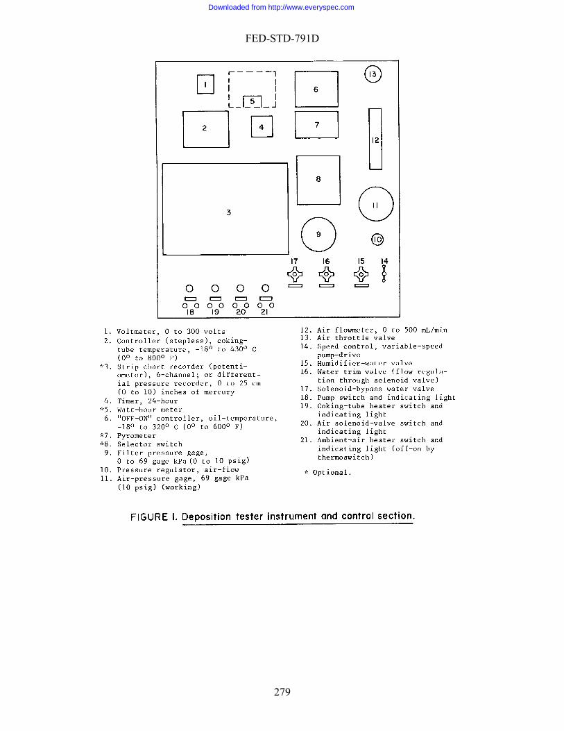
FED-STD-791D
279
Downloaded from http://www.everyspec.com
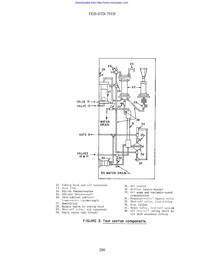
FED-STD-791D
280
Downloaded from http://www.everyspec.com

FED-STD-791D
281
Downloaded from http://www.everyspec.com
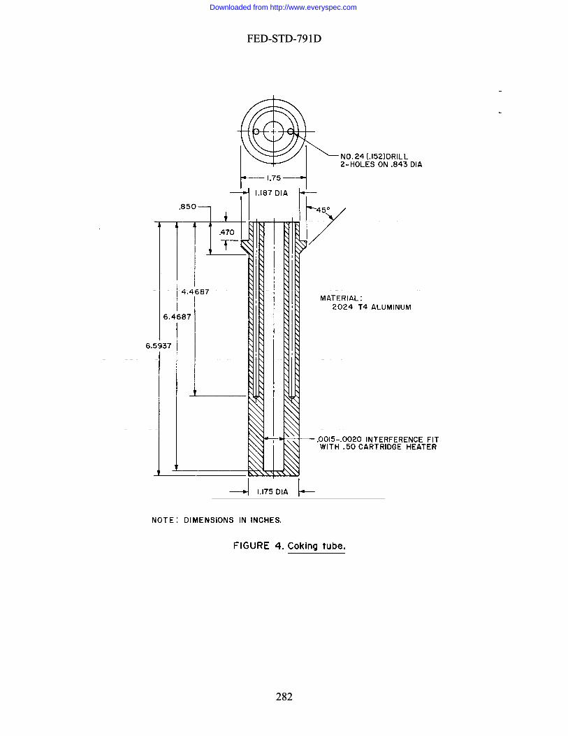
FED-STD-791D
FED-STD-791D
282
282
Downloaded from http://www.everyspec.com

FED-STD-791D
283
Downloaded from http://www.everyspec.com

FED-STD-791D
Method 5304.5
han eatment and measure, and spill practices
September 30 1986
CORROSIVENESS OF GREASES OR SEMI-SOLID PRODUCTS AT 25°C 1. SCOPE
1.1 This method is used for determining the presence of corrosive compounds in grease or other semi-solid products at room temperature (25°C; 77°F).
2. SUMMARY
2.1 The method consists of half-covering two copper strips with the product under test and examining for corrosion after 24 h. 3. SAMPLE
3.1 Approximately 5 g of material to be tested. 4. REFERENCES, STANDARDS, AND APPARATUS
4.1 Watch glass for covering sheets. 5. MATERIALS
5.1 CAUTION: SOME MATERIALS ARE TOXIC AND HAZARDOUS. The chemical materials listed in this section must be handled carefully. Federal Test Method 10000, Material Handling Safety Precautions, is a reference which lists all toxic and hazardous materials cited in FTMS 791. The synonyms, life hazard, flammability,
dling and storage precautions, emergency trf each chemical are explained.
5.2 Copper strips (2), (ASTM B 152/152M), 2.5 x 2.5 x 0.3 cm (1 x 1 x 1/8 in). 5.3 n-Hexane (ACS) [1,3,0]. 5.4 Acetone (ASTM D 329). 5.5 Abrasive paper (silicon carbide or alumina), various grade of grit. 5.6 Abrasive paper, silicon carbide, 240 grit. 5.7 Silicon carbide, 150 mesh. 5.8 Cotton, absorbent.
o
284
Downloaded from http://www.everyspec.com
FED-STD-791D
6. PROCEDURES
6.1 Prepare the copper strip as follows:
6.1.1 Using progressively finer gradesom one side of strip.
strips only with lint-free paper or tongs. Store strips immersed in acetone until ready for final polishing.
6.1.3 Remove strips from the acetone, and final polish one side to a mirror finish,
6.1.4 Clean all metal dust from the strip by rubbing vigorously with clean pads otton until a fresh pad remains unsoiled.
in fresh warm acetone, and allow
air dry.
NOTE 1:
of abrasive paper, remove all surface
blemishes fr
6.1.2 Polish strips with the 240-grit paper to remove any marks produced by the coarser abrasive. Do not touch the strips with the fingers. Handle
using 150-mesh silicon carbide grit (held on an acetone-moistened cotton pad).
of absorbent c
6.1.5 Wash strips in fresh warm n-hexane, then to
Caution. n-Hexane and acetone are toxic. Use only in a well ventilated es nor allow it to come in contact with the
skin. Keep all flames away from these materials.
6.2 Place approximately one-half of the sample on each strip, taking care to leave a
asses, and visually examine the sample for a green color.
stains. 7. CALCULATION
.1 This section is not applicable to the test procedure. 8. REPORT
.1 Report the lack or the presence of any evidence of corrosion (green color in sample
area. Do not breathe its fum
pproximately half of the polished surface exposed. 6.3 Cover the strips with inverted watch glasses, and let stand at room
temperature for 24 h. 6.4 Remove the watch gl 6.5 Wash the copper strips in non-corrosive n-hexane and inspect them for brown
7
8 or stain on copper sheets).
285
Downloaded from http://www.everyspec.com

FED-STD-791D
9. PRECISION
9.1 Precision data have not been developed for this method.
Method Prepared by:
Army - ME - 1986
286
Downloaded from http://www.everyspec.com

FED-STD-791D
Method 5305.1 September 30 1986
1. SCOPE
1.1 This method is used for determining the corrosive tendencigh temperatures. It consists of immersing copper and silver strips in the sample at
fo eigh ang
atu ngi r g box ted ica r 5 and
ht d o c sive ion ulti rom in l can
P AT
3 450 °F
1 ), cm .8 c 0. m (1-1/2 x
( % y), cm x 0.32 cm
G
lver p v ally ea ith
a , 0 (m , c inin lfuric acid elec yte.
4.9 Watch glass (2), 10 cm or larger.
CORROSIVENESS OF LUBRICANTS AT 232°C (450°F)
ies of lubricants at h232°C (450°F) for 50 h, and then examining them r w t ch e. 2. SUMMARY
2.1 This method duplicates an extended, high-temper re e ne o ear environment. Copper and silver strips are exposed to the hea lubr nt fo 0 h carefully cleaned and weighed for loss of weig ue t orro act res ng fcorrosive decomposition products being formed ubri t. 3. SAMPLE SIZE
3.1 Approximately 400 mL of lubricant to be tested. 4. REFERENCES, STANDARDS AND A PAR US
4.1 Oven, explosion-proof, 232° °C ( ° 5 ). 4.2 Copper strip (ASTM B 152/B 52M 3.8 x 3 m x 16 c
1-1/2 x 1/16 in). 4.3 Silver strip, pure electrolytic 99.9 purit 3.8 x 3.8 cm
(1-1/2 x 1-1/2 x 1/8 in). 4.4 Beakers (2), borosilicate glass, riffin low-form, 400 mL. 4.5 Supports (2), glass (for holding copper or si stri ertic in b ker w
point contact, so that strip does not touch the sides or bottom of the beaker). 4.6 Balance, sensitivity 0.1 mg. 4.7 Electrolytic bath, carbon-rod node .5 A in.) onta g su
solution (5% by weight in distilled water) as the trol 4.8 Tongs, stainless steel.
287
Downloaded from http://www.everyspec.com

FED-STD-791D
5. MATERIALS
5.1 CAUTION: SOME MATERIALS ARE TOXIC AND HAZARDOUS. The chemical mate Test Method 0000, Material Handling Safety Precautions, is a reference which lists all toxic and
aterials cited in FTMS 791. The synonyms, life hazard, flammability, andling and storage precautions, emergency treatment and measures, and spill practices
of each
-Trichloroethane (reagent grade) [2,1,0].
FFF grade.
quivalent).
uric acid [3,0,2] saturated with
otassium or sodium dichromate [1,0,1], technical grade).
NOTE:
rials listed in this section must be handled carefully. Federal1hazardous mh
chemical are explained. 5.2 Solvent, dry-cleaning (A-A-59601D).
5.3 1,1,1
5.4 Acetone (ACS) [1,3,0]. 5.5 Nitric acid solution (3 parts concentrated nitric acid and 7 parts distilled
water) [2,0,0].
5.6 Pumice,
5.7 Eraser (Eberhard Faber "Pink Pearl" No. 100, or e
5.8 Cleaning solution, glass (concentrated sulfp
If the glass-cleaning solution cannot r move all deposits (see 6.1) use a e
s:
lass-cleaning for at least 8 h or until all traces of deposits are
ngs, clean the copper and silver strips in separate bath solution
special cleaner, such as Turco Transpo cleaner (Turco Products Co., Chicago, IL).
5.9 Distilled water.
6. PROCEDURE
6.1 Clean two glass supports and two 400-mL beakers as follow
a. Rinse with dry-cleaning solvent to remove excess oil. b. Place each support in its beaker, and fill each beaker with g
solution. Let them stand removed.
c. Remove from the glass-cleaning solution, and rinse the glassware with running tap water followed by distilled water.
6.2 Handling only with to
as follows: s
a. Wash with dry-cleaning solvent.
288
Downloaded from http://www.everyspec.com

FED-STD-791D
b. Immerse in dilute nitric acid solution for 15 1 s. c. Rinse the silver strip only in hot 82° to 100°C (180° to 212°F) tap water, and
CAUTION:
then wet polish with pumice. (No polishing of the copper strip is required.) d. Rinse the strip in hot tap water, and then in hot distilled water. e. Dip in acetone, and allow to air dry.
6.3 Handling the strips with tongs, weigh each strip to the nearest 0.1 mg.
In succeeding steps the strips must be handled only with tongs until
e 6.9) at the end of the test.
ce each support in a separate beaker so that the strip does not touch the sides of the beaker.
.5 Add 200 mL of the sample to each beaker, and cover with watch glass to avoid e
.6 Store both beakers in an oven for 50 h at 232° 3°C (450° 5°F).
the oven and allow t
1,1practicable.
b. ain, place the strip (as a cathode) in the electrolytic .5 A.
r, while rubbing it with an eraser. strip with distilled water, then with acetone, and air dry both strips.
e in weight of ach s s
7. CALC L
7.1 s
after they have been weighed (se
6.4 Mount each strip in a glass support then pla
6vaporation losses. 6 6.7 At the end of the heating period, remove both beakers fromhem to cool to room temperature. 6.8 Remove the copper and silver strips from the supports and clean them as
follows:
a. Wash each strip with successive portions of fresh, hot 60°C (approx. 140°F) ,1-trichloroethane, to remove as much discoloration and deposit as
If carbonaceous deposits rembath for 10 min at 0
c. Wash each strip in hot, running wated. Rinse each
6.9 Weigh each strip to the nearest 0.1 mg, and compute the chang
e trip ( ee 7.1). 6.10 Measure the surface area of each strip (both sides) (see 7.1).
TIONS U A
The calculations to determine mg/cm2 as follow
L * W * 2W - W 21 = CW
289
Downloaded from http://www.everyspec.com

FED-STD-791D
whCWW1 = WWL = length of metal strip in cm.
. REPORTING
8.1 Repor .
9. PRE
.1 Repeatability. Results of each test obtained by one operator using the same apparat
.2 Reproducibility. Results of each test obtained by different operators or differen
ere: = change in mg/cm2
original weight in mg. 2 = final weight in mg. = width of metal strip in cm.
8
t change in weight in mg/sq cm rounded off to the nearest mg
CISION
9us must not vary by more than that shown in Table 1. 9t apparatus must not vary by more than that shown in Table 1.
TABLE 1 - Precision.
Permissible variation
Av
mg/cm2 Repeatability
Reproducibility
erage weight change
0 to 0.46
Above 0.46
0.046 mg/cm2
10%
0.09 mg/cm2
20%
:
Method prepared by
Air Force - SFTL - 1986
290
Downloaded from http://www.everyspec.com
FED-STD-791D
Method 5306.5 September 30 1986
EMULSIFIABLE CUTTING FLUIDS . SCOPE
1.1 This method is used for determining the corrosiveness of soluble cutting oils and che
t air into the test tube at a specified rate and temperature. The strip is examined for conformance with specification require
3. SAMPLE SIZE
3.1 Approximately 10 mL of
4 R RD , AND APPARATU
4.1 D 130 - Detection of ion from etrol the Copper Strip Tarnish Test.
4.2 Source of clean compressed air. 4.3 Air pressure regulator. 4.4 Approximately 7.3 m (24 ft) of 0.6-cm (1/4-in) I.D. rubb 4.5 Four screw type pinch clamps. 4.6 One bubble tower, capacity 500 mL. 4.7 Four test tubes, approximately 3.2 cm O.D. by 20.0 cm long. 4.8 Four pieces of glass tubing, 0.6 .1 cm I.D. by 23.0 1 cm long. 4.9 Forceps, stainless steel. 4.10 Graduated cylinder, capacity, 250 mL. 4.11 Magnifier, 5X.
CORROSIVENESS OF
1
mical type metal working fluids on brass, copper, cast iron, and steel. 2. SUMMARY
2.1 The test consists of placing a metal strip and the sample in a test tube. A bubble tower filled with sodium hydroxide is used to permi
ment.
the fluid to be tested.
. EFERENCES, STANDA S S
ASTM Copper Corros P eum Products by
er tubing.
0
291
Downloaded from http://www.everyspec.com

FED-STD-791D
5. MATERIALS
5.1 CAUTION - SOME MATERIALS ARE TOXIC AND HAZARDOUS. The chemical materials listed in this section must be handled carefully. Federal Test Method 10000, Mate ll toxic and
azardous materials cited in FTMS 791. The synonyms, life hazard, flammability, mergency treatment and measures, and spill practices
f each chemical are explained.
25% NaOH y weight [3,0,1].
5.3 n-Hexane, commercial [1,3,0].
istilled water.
tissue.
(3 � l/2 � 1/8 in) STM B 152/152M, electrolytic tough pitch, cold-rolled, half-hard temper).
5.8 Two brass strips, approximately 76 � 13 � 0.32 cm (3 � 1/2 � 1/8 in) (ASTM B 121/B
.9 Two cast iron strips, approximately 76 � 13 � 0.32 cm ( 3 � 1/2 � 1/8 in) (ASTM
roximately 76 � 13 � 0.32 cm (3 � 1/2 � 1/8 in) (QQ-S-698, physical quality, cold-rolled, half-har per). 6. PROC
tal listed in section 4 in accordance with ASTM
parate test tube. Place the d bottle tightly
NOT
rial Handling Safety Precautions, is a reference which lists ahhandling and storage precautions, eo
5.2 500 mL of sodium hydroxide solution containing approximately
b
5.4 1,1,1-Trichloroethane (ASTM D 4126). 5.5 D
5.6 Cleaning
5.7 Two copper strips, approximately 76 � 13 cm by 0.32 cm(A
121M, ASTM B 36/ B 36M, composition 2 [cartridge brass], half-hard temper). 5 A 48, class 20, strip only). 5.10 Two steel strips, app
d temper - CR half-hard No. 2 tem
EDURE
6.1 Prepare two strips of each type of me D 130. 6.2 Using the forceps, place one strip of each type of metal in a se
uplicate strips in a bottle filled with the normal hexane. Keep thisstoppered until time to examine the strips.
E: Caution. Normal hexane is flammable. Use only in a well ventilated area. Keep all flames away from the normal hexane.
292
Downloaded from http://www.everyspec.com
FED-STD-791D
6.3 Prepare a solution of the cutting fluid by placing 190 mL of distilled water nd 10 mL of the cutting fluid in a 250-mL graduated cylinder. Stopper the graduated
cylinde
tubing, by means of rubber tubing and an appropriate manifold or series of Y-tubes, to the discharge outlet of the bubble tower. Place a er tubing leading to the glass tubes.
tube to the bottom of a test tube and adjust the air flow into each tu ately one bubble per second by means of the air pressure regulat
.9 At the end of the test period, remove the metal strips from the test tubes. If the cu
chemical solution type, wash the metal strips in distilled water and blot them dry with facial t
etal strips from the bottle of normal hexane and permit
. CALCULATIONS
7.1 This section is not applicable to the test procedure.
G
Method Prepared By:
Army - AR – 1986
ar and invert it several times. Continue inverting the graduate until a uniform
mixture is obtained. 6.4 Place 50 mL of the cutting fluid solution in each of the four test tubes. Mark
the fluid level on the outside of each test tube and maintain this level by the addition of distilled water during the course of this test.
6.5 Fill the bubble tower with the sodium hydroxide solution and connect the
tower, through the air pressure regulator, to the source of compressed air by means of the rubber tubing.
6.6 Connect each length of glass
screw type pinch clamp on each piece of rubb 6.7 Insert each glasse to produce approximb
or and pinch clamps.
6.8 Permit the air to bubble into the tubes at room temperature 24° 3°C (75° 5°F) for a period of 48 h.
6tting fluid under test is a soluble oil type, wash the metal strips in
1,1,1-trichloroethane and permit them to air dry. If the cutting fluid under test is a
issue.
.10 Remove the duplicate m6them to air dry. Examine the exposed and duplicate metal strips under 5X
magnification for conformance with the specification requirement. 7
8. REPORTIN
8.1 Comply with specification requirement.
9. PRECISION
9.1 Precision data have not been developed for this method.
293
Downloaded from http://www.everyspec.com
FED-STD-791D
COR
etals.
est tube, borosilicate, standard-wall; 5.0 0.3 cm O.D., 50.0 1 cm long; with open end formed as a male ground-glass joint, joint is T 71/60.
joint to mate with the 60; drip tip in Ts joint, 60 cm, min length; tabulations are parallel condenser, they are about 1.0 cm O.D.; open end has an I.D. of
pprox
Method 5308.7 September 30, 1986
ROSIVENESS AND OXIDATION STABILITY OF LIGHT OILS (METAL SQUARES)
1. SCOPE
1.1 This method is used for testing hydraulic oils (spindle oils), and similar, highly refined, light oils to determine their ability to resist oxidation and their tendency to corrode various m
2. SUMMARY
2.1 Metal specimens are suspended in a measured amount of lubricant. The oil, at an elevated temperature, is blown with air for a period of time. When the test is completed, the oil is tested to determine the extent of degradation. The metal specimens are examined for corrosion.
3. SAMPLE SIZE
3.1 Approximately 225 mL of oil to be tested. 4. REFERENCES, STANDARDS, AND APPARATUS
4.1 Ts
4.2 Condenser, Allihn type. Borosilicate, 3.5 cm O.D. (min.) by 300 2.0 cm
long jacket, with the lower end formed as a female ground-glass test tube; joint is Ts 71/t opposite sides of thea
a imately 2.2 cm.
NOTE 1: The test tube (4.5.1) and condenser (4.5.2) may be obtained from:
J8225 Parkview Avenue
diana
., length at least 5.0 m greater than com
awn to a 0.16 0.04 cm (l/16 1/64 in) diametetube with a 0.16 0.04 cm (1/16 1/64 in) bore may be used.
ohn A. Glover
Munster, In
4.3 Air tube, borosilicate, standard wall; 0.6 to 0.8 cm O.Dbined length of assembled test tube and condenser, about 94.0 cm, c
with one end dr r orifice. A capillary
294
Downloaded from http://www.everyspec.com
FED-STD-791D
4.4 Bath constant - temperature, capable of maintaining the sample 0.5°C (1°F) of the specified temperature.
NOTE 2:
A liquid medium bath is not to be used over 135°C (275°F). Abo135°C (275°F) use an aluminum block. The heaters should be placed
num block.
ve on
the sides of the alumi Base heaters are to be avoided. A satisfactory heater arrangement is described in method 350 of this standard. Unless otherwise specified the bath temperature is 121°C
ce, sensitivity 0.1 mg.
, stainless-steel.
ning brush, or equal).
lists all toxic and hazardo
holes (Figure l), as follows:
mild (ASTM 1008A/1008M, class l, commercial bright finish
(250°F) for all oils except spindle oils where it is 100°C (212°F).
4.5 Assembly fixture, wood (slotted to hold metal squares for tying with cord, as hown in Figure 1). s
4.6 Balan 4.7 Microscope, 20 diameter magnification. 4.8 Air-supply, clean, dry, low-pressure, 3-5 0.5 L/hr. 4.9 Forceps 4.10 Brush, short-bristled, stiff (typewriter clea
5. MATERIALS
5.1 CAUTION: SOME MATERIALS ARE TOXIC AND HAZARDOUS. The chemical materials listed in this section must be handled carefully. Federal Test Method 10000, Material Handling Safety Precautions, is a reference which
us materials cited in FTMS 791. The synonyms, life hazard, flammability, handling and storage precautions, emergency treatment and measures, and spill practices of each chemical are explained.
5.2 Metal squares (l each) 0.081 cm (0.032 in) thick by 2.5 cm (l in) square, with
nd without two drilleda 5.2.1 Copper, electrolytic (ASTM B 152/152M). 5.2.2 Steel, carbon,
). 5.2.3 Aluminum alloy (ASTM B 209, temper T-3 or T-4). 5.2.4 Magnesium alloy (SAE AMS 4375, 4376, 4377) 5.2.5 Anodes, Cadmium (A-A-51126B).
295
Downloaded from http://www.everyspec.com

FED-STD-791D
5.3 Cord (cotton, nylon, or linen), light-weight, clean (for tying metal squares together).
NOTE 3: A fine stainless steel wire may be used to tie the metal squares together when a test temperature of over 204°C (400°F).
rasive paper (silicon carbide or alumina), various grades of grit.
rasive paper, silicon carbide, 240 grit.
5.4 Ab 5.5 Ab
bsorbent.
D 4126).
-N-97) [1,4,0].
. PRO
ine the acid number of the sample by method ASTM D 664 or D 974, hiche
and steel squares. For testing spindle
r, remove all surface blemish d any burrs from the drilled
NOT
5.6 Silicon carbide grains, 150 mesh. .7 Cotton, a5
.8 1,1,1-Trichloroethane (ASTM5
.9 Acetone (ACS), sulfur-free [1,3,0]. 5
.10 Laboratory filter paper. 5
.11 Naphtha, Aromatic (TT5
CEDURE 6
6.1 Determ
w ver is applicable. 6.2 Determine the viscosity in centistokes of the sample by method ASTM D 445
at 40°C unless otherwise specified. 6.3 Wash a length of the cord by boiling it in distilled water for 10 min, and
allow it to dry. 6.4 Prepare the solid cadmium squares by removing any burrs from the drilled
holes.
.5 Prepare the aluminum copper, magnesium, 6 oil, use only metal squares of copper and steel. The squares are prepared as
follows: 6.5.1 Using progressively finer grades of abrasive pape
s from both sides and all four edges of each square, aneholes. E 4. Caution. In all succeeding steps,
paper only, until the final weighinghandle the squares with tongs or filter (see 6.11).
296
Downloaded from http://www.everyspec.com
FED-STD-791D
6.5.2 Polish each square with the 240 grit paper to remove any marks produced by coarser abrasive. Store squares immersed in separate containers of acetone until ready
r final polishing.
NOTE 5:
fo
ell ventilated area. Keep all flames away from acetone.
.5.3 Remove each square from the acetone, and final polish both sides to a
mirror eld on an acetone-moistened cotton pad).
.5.4 Clean all metal dust from the square by rubbing vigorously with clean pads of abso pad remains unsoiled.
s follows:
oroethane (approximately 54°C [130°F]), rinse with 1,1,1-trichloroethane, and allow them to air-dry.
NOTE 6:
Caution. Acetone is flammable. Use only in a w
6finish, using 150 mesh silicon carbide grit (h
6rbent cotton until a fresh 6.6 Continue preparation of all five squares a 6.6.1 Wash squares in warm 1,1,1-trichl
Caution. 1,1,1-Trichloroethane is toxic. Do not breathe its fumes nor in.
diately weigh each square to within 0.1 mg.
hat the magnesium and copper squares do not touch each other. (When testing spindle oil, the metal squares shall be placed in the test tube in such a manner
.6.4 Using only forceps to handle the clean cord, tie the squares together as shown
.7 Prepare new test set up as follows:
6.7.1 Insert the tied metal squares in the test tube, positioning the squares vertically (so that the air tube can be inserted to touch the bottom of the test tube). Weigh
7.2 Add 100 l mL of sample to the test tube, reweigh the air tube, test tube, and contents together to within 0.1 g, and determine weight of sample added.
be is submerged in the bath operating at specified temperature.
allow it to come in contact with the sk
6.6.2 Imme
6.6.3 Arrange squares in the wooden assembly fixture in the pattern shown in Figure l, making certain t
as to form a "V" in the bottom of the test tube.) 6in Figure 1. 6
the air tube, test tube, and contents together to within 0.1 g. 6.
6.7.3 Assemble the test tube and condenser and mount the assembly so that 30
5 cm of test tu 6.7.4 Start the flow of cooling water through the condenser jacket.
297
Downloaded from http://www.everyspec.com

FED-STD-791D
6.7.5 Insert the air tube (orifice-end down) through the condenser and into the sample and support it so that its orifice is within 0.3 cm (l/8 in) of the bottom of the tube. (When testing spindle oil, orifice should be within 0.6 cm (l/4 in) of the junction of the
etal square.)
6.8 Connect the source of clean, dry air (3 0.2 L/hr for spindle oils; 5 0.5 L/hr r other oils) to the air tube and allow the air to flow for 168 h.
test setup as follows:
.9.2 Remove test tube from constant-temperature bath, and wipe off the outside of the t
NOT
m
fo 6.9 At the end of the specified period, shut off the air-flow, and disassemble, and
check 6.9.1 Remove air tube and disconnect condenser. 6ube with a naphtha-dampened cloth. E 7: Caution. Naphtha is flammable. Use only in a well ventilated area. Keep
all flames away from naphtha.
6.9.3 Reweigh the air tube, test tube, and contents to within 0.1 g, determine ple remaining, and compute the percentaweight of sam ge of weight loss resulting from
vaporation of sample (see 7.1). (If the evaporation loss is greater than 8%, leakage is present g fresh sample and new metals squares.)
.10.1 Using forceps, wash each square individually in warm 1,1,1-tr °F]).
.11.1 Reweigh each square to the nearest 0.1 mg and compute (in mg/cm2 of surface
.11.2 Using the 20-power microscope, carefully examine each square, and note any evi
e. Correct the leak, and repeat the determination, usin
6.9.4 Using forceps, withdraw the metal squares from the test tube, and remove
the cords holding them together. (Retain the test tube and sample for further examination.)
6.10 Prepare squares for examination as follows: 6ichloroethane (approximately 54°C [130 6.10.2 Repeat the washing, using fresh 1,1,1-trichloroethane and scrubbing the
squares with the short-bristled brush, until the 1,1,1-trichloroethane shows no additional discoloration, and allow the squares to air-dry.
6.11 Examine each square as follows: 6) the change in weight of each square (see 7.2). 6dence of pitting or etching.
298
Downloaded from http://www.everyspec.com
FED-STD-791D
6.11.3 Note the color of any stains present on the copper square. 6.12 Examine the sample in the test tube as follows: 6.12.1 Inspect for any evidence of insoluble or gummy material as required by
the spe
.12.2 Determine the acid number by method ASTM D 664 or D 974, whichever is appli
.12.3 Determine viscosity in centistokes by method ASTM D 445 at 40°C (104°F e percentage change from the original centistoke viscosity (see 6.2 and 7.4).
e evaporation loss W1 =
ange in metal square weight:
(mg/cm ) M2 = final weight in g M1 =W = width of metal square in cm L =
.3 Change in acid number:
cification and record. 6cable, and calculate the change from the original acid number (see 6.1 and 7.3). 6) (unless otherwise specified), and calculate th
7. CALCULATIONS
7.1 Evaporation loss:
100 * W
= L1
21 W - W
where: L = ercentagp
initial weight W2 = final weight
.2 Ch7
)L * (W * 2 2100 * )M - M( 0 = M 12
where: M = change in metal weight per surface area 2
original weight in g
length of metal square in cm
7
299
Downloaded from http://www.everyspec.com

FED-STD-791D
AN - AN = A 12
wheA = change in acid number AN
r
7.4
ity V2 = stokes V1 = ntistokes
8. REPORTING
8.1 Report as corrosiveness stability the change in weight of each of the metal uares in mg/cm2 and the appearance of each of the metal squares.
ility of the fluid the result of the insoluble gummy ma change in acid number, and the change in viscosity. . PRECISION
9.1 Precision data have not been developed for this method.
Method Prepared by:
Army - ME - 1986
re:
2 = final acid number AN1 = original acid numbe
Change in viscosity:
100 * V
VV = C1
12 -
where: C = change in viscos
final viscosity in centi original viscosity in ce
sq 8.2 Report as oxidation stab
terial inspection, the
9
300
Downloaded from http://www.everyspec.com

FED-STD-791D
Method 5309.5 September 30, 1986
ORROSIVENESS OF GREASES (Copper Strip, 100°C)
1.
1.1 This method is used for determining the corrosive properties of grease at elevated temperatures. . SUMMARY
s of partially immersing a copper strip in the sample at 100°C for sample and strip for evidence of corrosion. .
ximately 20 mL of grease to be tested.
ately 2.5 cm diameter by 10 cm long.
4.5 Forceps, stainless steel.
5. MATERIALS
5.1 CAUTION: SOME MATERIALS ARE TOXIC AND HAZARDOUS. The hemical materials listed in this section must be handled carefully. Federal Test Method 0000, Material Handling Safety Precautions, is a reference which lists all toxic and azardous materials cited in FTMS 791. The synonyms, life hazard, flammability,
d storage precautions, emergency treatment and measures, and spill practicesof each chemical are explained.
5.2 Copper strip (Copper and Brass Research Association No. 110 Electrolytic
Grade), soft tempered, annealed, approximately 1.3 � 7.6 � 0.15 cm or 0.3 cm.
C
SCOPE
2
2.1 The test consist4 2 h then visually examining both
3 SAMPLE SIZE
3.1 Appro 4. REFERENCES, STANDARDS, AND APPARATUS
4.1 Oven, 100°C. 4.2 Microscope, approximately 60X diameter magnification. 4.3 Test tube, clean, dry, approxim 4.4 Support (beaker) for holding test tube approximately vertical.
c1hhandling an
301
Downloaded from http://www.everyspec.com
FED-STD-791D
5 dete 130) [1,3,
5.4 Acetone (ACS Grade) [1,3,0]. 5.5 Polishing materials.
Fine silicon carbide or alumina grit paper.
5.5.3 150-mesh silicon carbide grains.
. PROCEDURE
paration - Remove all blemishes from all six sides of the strip with silicon-carbide or alumina grit paper of such degree of fineness as is needed to
Note 1). Finish with 240-grit silicon carbide paper, removing all marks that have been made by other grades
cetone (see Note 2) from which it may be with-drawn immediately for final polishing or in which it may be
se.
NOT
.3 n-Hexane (ACS Grade) non-corrosive (as rmined by ASTM D0].
5.5.1
5.5.2 240-grit silicon carbide paper.
6
6.1 Prepare finish of copper strip as follows:
a. Surface pre
accomplish the desired results effectively (see
of paper used previously. Immerse the strip in a
stored for future u
E 1: As a practical manual procedure for surface preparation moisten it with kerosene or acetone and rub the strip against the paper with a rotary
ashless filter paper. Alternatively the strip may be prepared by use of motor
oth.
NOT
motion protecting the strip from contact with the finger with an
driven machines using appropriate grades of dry paper or cl
E 2: Caution. Acetone is both toxic and flammable. Use only in a well ventilated area. Do not breathe its fumes nor allow it to come in contact
the skin. Keep all flames away from the acetone. b
uch with fingers. Clamp in a vise and polish the main surfaces with silicon carbide grains on absorbent cotton. Rub in the direction of
strip by ains
with
. Final polishing - Remove a strip from the acetone. Holding it in the fingers protected with the ashless filter paper, polish first the ends and then the sides with 150-mesh silicon carbide grains picked up from a clean glass plate with a pad of absorbent cotton moistened with a drop of acetone. Wipe vigorously with fresh pads of absorbent cotton and subsequently handle only with stainless steel forceps; do not to
the long axis of the strip, carrying the stroke beyond the end of the strip before reversing the direction (see Note 3). Clean all metal dust from therubbing vigorously with clean pads of absorbent cotton until a fresh pad rem
302
Downloaded from http://www.everyspec.com
FED-STD-791D
unsoiled. When the strip is clean, immediately immerse it in the prepared sample.
NOT
E 3: It is important to polish the whole strip uniformly to obtain a uniformly strained strip. If the ends show wear (surface elliptical) they will likely
sion than the center. The use of a vise will facilitate uniform polishing.
.2 Fill test tube with sample to depth of 5 cm. Remove air pockets from the
grease ble as it is being filled.
copper strip until it touches the bottom of e tube.
6.4 Place the test tube (supported approximately vertically in 100°C) oven for 24 h (unle
cool at ro 6
n-hexane
NOTE
show more corro
6by tapping the tube on the bench or ta 6.3 Using stainless steel forceps, insert
th
ss otherwise specified).
6.5 At the end of the specified time, remove test tube from oven and allow it to om temperature.
.6 Using forceps, remove copper strip, and wash in non-corrosive ACS grade . (See Note 4.)
4: Caution. n-Hexane is both toxic and flammable. Use only in a well ventilated area. Do not breathe its fumes nor allow it to come in contact
7. CALCULA
7.1 Th
. REPORTING
ecolor than the
micro 8
9. PREC
9
Navy - NADC - 1986
with the skin. Keep all flames away from the n-hexane.
TIONS
is section is not applicable to the test procedure. 8
8.1 R port whether the section of the strip immersed in the sample is darker in exposed section.
8.2 Report by describing any corrosion of the strip when examined under a scope of approximately 60 diameters magnification.
.3 Report development of any green color in the grease.
ISION
.1 Precision data have not been developed for this method.
Method prepared by:
303
Downloaded from http://www.everyspec.com
FED-STD-791D
September 30 1986
1. SCOPE
1.1 This method is used for measuring the corrosiveness of lubricating oils on lead in
2. SUMMARY
It consists of rotating panels of lead and copper in the test lubricant under specific conditions, and determining the degree of corrosion from the change in weight of the lead
3. SAMPLE SIZE
500 mL of the oil to be tested. 4. REF
4.1 Sample tube, SOD (Standard Oil Development), available from Koutes Co., Sp07003 (see Fig
perature, 163° " 1°C (325° " 2°F), minimum depth 31 cm
4.3 Motor, stirring, 600 " 50 rpm.
ry, approximately 7 gage kPa (1 psig) to provide flow of 0.940 " 3
"
5.1 CAUTION: SOME MATERIALS ARE TOXIC AND HAZARDOUS. Thematerials references and standards listed in this section must bFederal Test Method 10000, Material Handling Safety Precautions, is a reference whichlists all toxic and hazardous materials cited in FTMS 791. The syno
Method 5321.2
CORROSION OF LEAD BY LUBRICATING OILS
the presence of a copper catalyst.
2.1
panel.
3.1 Approximately
ERENCES, STANDARDS, AND APPARATUS
ruce St., Vineland, NJ 08360 or SGA Scientific, Inc., 735 Broad St., Bloomfield, NJ ure 1).
4.2 Bath, constant-tem(12 in).
4.4 Shaft, stirring, with attaching hardware (see Figure 2). .5 Air supply, clean, d4
0.047 L/min (2 " 0.1 ft /h). .6 Balance, sensitivity 1 mg. 4
4.7 Forceps, stainless steel.
ALS5. MATERI
e handled carefully.
nyms, life hazard,
304
Downloaded from http://www.everyspec.com
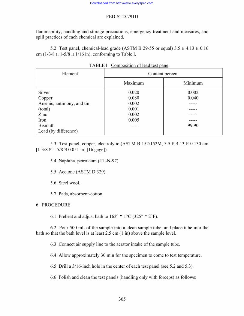
FED-STD-791D
flammab emergency treatment and measures, and ility, handling and storage precautions,ctices of each chemical are explained.
5.2 Test p .5 H 4.13 H 0.16
m (1-3/8 1-5/8 H 1/16 in), conforming to Table I.
TABLE I. Composition of lead test pane
spill pra
anel, chemical-lead grade (ASTM B 29-55 or equal) 3c H .
Content percent
Maximum
Minimum
Element
Silver Coppe
Zinc
Bismuth Lead
0.020
0.001 0.002 0.005 -----
0.002
----- ----- -----
99.90
r Arsenic, antimony, and tin (total)
0.080 0.002
0.040 -----
Iron
(by difference)
5.3 Test panel, copper, electrolytic (ASTM B 152/152M, 3.5 H 4.13 H 0.130 cm -3/8 H
.6 Steel wool.
6. PRO
sample tube, and place tube into the bath so m (1 in) above the sample level.
o the aerator intake of the sample tube.
approximately 30 min for the specimen to come to test temperature.
1-5/8 H 0.051 in] [16 gage]). 5.4 Naphtha, petroleum (TT-N-97).
[1
5.5 Acetone (ASTM D 329). 5 5.7 Pads, absorbent-cotton. CEDURE
6.1 Preheat and adjust bath to 163° " 1°C (325° " 2°F). 6.2 Pour 500 mL of the sample into a clean that the bath level is at least 2.5 c 6.3 Connect air supply line t 6.4 Allow
6.5 Drill a 3/16-inch hole in the center of each test panel (see 5.2 and 5.3). 6.6 Polish and clean the test panels (handling only with forceps) as follows:
305
Downloaded from http://www.everyspec.com
FED-STD-791D
a. Polish the faces and edges of the panels with steel wool until a uniform bright surface is produced.
CAUTION: When polishing the lead panel, avoid excessive pressure which may
cause the steel wool to become embedded in the lead.
b. Remove all loose p ked cotton pads. c. Rinse with fresh naphtha, and allow to air dry.
6.7 Using forceps to handle e pane weight o the lead panel to the
nearest mg.
Clean the stirrer shaft and panel attaching hardware by rinsing with naphtha, using naphtha-soaked cotton pads or steel wool as required. Rinse in clean naphtha, and allow to air dry.
6.9 Using forceps to handle the panels, both panels on the shaf own
in Figure 2.
6.10 Attach stirrer motor to the shaft, and lower the shaft into the sample tube so he cen
y adjust the air flow 0.940 " 0.047 L/min (2 " 0.1 ft " 1 min.
bly, and detach the lead panel from the shaft. Swab t aphtha-soaked cotton pads to remove any loose surface deposits. R h naphtha and then with acetone, and allow the panel to air dry.
o change in the weight.
) of the exposed surface area (in
9. PRE
st not differ:
articles from the panels, using naphtha-soa
th l, record the f
6.8
mount t as sh
t ter of the lead panel is centered in the tube approximately 7.5 cm (3 in) from the bottom.
6.11 Start the stirrer and immediatel3/h). Continue the operation for 60 .12 Remove the stirrer assem6
he lead panel lightly with ninse with fres
.13 Reweigh until there is n6
. CALCULATIONS 7
7.1 Calculate the change in weight in mg/cm2 (mg/in2
cluding the faces and edges, but excluding the areas covered by the washers). 8. REPORTING
8.1 Report the change in weight to the nearest 1.5 mg/cm2 (mg/in2).
CISION
9.1 Repeatability. Results by one operator using the same apparatus mu
306
Downloaded from http://www.everyspec.com

FED-STD-791D
a. By more than 0.15 mg/cm2 (1 mg/in2) if the change in weight does not exceed 1.5 mg/cm2 (10 m 2g/in );
b. By more than 10% of the average, if the change in weight exceeds 1.5
9.2 Reproducibility. Results from different operators or different apparatus must
not diff
. By more than (2 mg/in2) if the change in weight does not exceed 1.5 mg/cm2
g/in ).
Air Force - SFTL - 1986
or
mg/cm2 (10 mg/in2).
er:
a(10 mg/in2),
or
b. By more than 20% of the average, if the change in weight exceed 1.5 mg/cm2 (10 m 2
Method prepared by:
307
Downloaded from http://www.everyspec.com

FED-STD-791D
308
Downloaded from http://www.everyspec.com
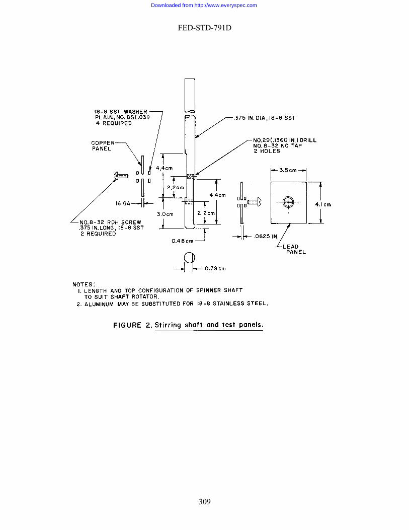
FED-STD-791D
309
Downloaded from http://www.everyspec.com

FED-STD-791D
Method 5322.2 September 30, 1986
CORROSIVENESS OF OIL ON A BIMETALLIC COUPLE 1. SCOPE
1.1 This method is used for determining the corrosive effect (chemical or electrochemical) of an oil on a bimetallic couple. 2. SUMMARY
2.1 The method consists of fitting a brass clip to the oil-coated surface of a steel disk, storing the assembly in a humidity cabinet for 10 days, and visually inspecting the assembly for evidence of corrosion. 3. SAMPLE SIZE
3.1 Approximately 2 g of the oil to be tested. 4. REFERENCES, STANDARDS, AND APPARATUS
4.1 Humidity cabinet, approximately 50% relative humidity. 4.2 Magnifier, 10X. 4.3 Desiccator, containing desiccant. 4.4 Stirring rod, glass.
5. MATERIAL
5.1 CAUTION: SOME MATERIALS ARE TOXIC AND HAZARDOUS. The hemical materials listed in this section must be handled carefully. Federal Test Method 0000, Material Handling Safety Precautions, is a reference which lists all toxic and
hazardous materials cited in FTMS 791. The synonyms, life hazard, flammability, handling and storage precautions, emergency treatment and measures, and spill practices of each chemical are explained.
5.2 Steel disks, (3) (ASTM A 322, composition G52986), heat treated to
Rockwell C-62, 2.54 cm (1 in) diameter by 1.25 to 2.54 cm (1/2 to 1 in) thick ground on one side to 0.508 μm (20 μin) rms prior to hand-polishing (see 6.1.2). This treatment need not be repeated prior to each test unless the disks are badly corroded.
c1
310
Downloaded from http://www.everyspec.com

FED-STD-791D
5.3 Clips, (3), brass (ASTM B 121 12 , A B 36/B36M, compo/ B 1M STM sition pring temper, fabricated to dimensions show
5.4 Abrasive papers, silicon-carbide or aluminum oxide, 150, 240, 400, and 600
grit.
N:
2), s n in Figure 1.
CAUTIO Do not use papers containing iron oxide.
5.6 Acetone (ASTM D 329).
5.7 Etching solution, consisting of:
5.7.2 Nitric acid (ACS), concentrated, 225 mL [2,0,0].
5.7.3 Sulfuric acid (ACS), concentrated, 300 mL [3,0,2].
5.7.4 Hydrochloric acid (ACS), concentrated, 8 mL [3,0,0].
5.8 Methyl alcohol (ACS), absolute [1,3,0].
.9 Distilled water. 6. PROCEDURE
.1 Prepare the three steel disks as follows:
6.1.1 Slush the disks in the methyl alcohol to remove traces of coolant used in
NOT
5.5 Cloth, lint-free, clean, dry.
5.7.1 Distilled water, 450 mL.
5
6
grinding.
E Caution. Methyl alcohol is both toxic and flammable. Use it only in a well ventilated area. Do not permit it to come in contact with the skin or breathe its fumes. Keep all flames away from this material.
6.1.2 Polish the surface-ground side using 150-, 240-, 400-, and 600-grit silicon
carbide or aluminum oxide paper in succession. Perform each polishing operation at right angles to the previous one, and continue until all cross scratches from the previous operati
ul
on are removed. 6.1.3 Clean the disks by wiping with the clean, dry, lint-free cloth, being caref
not to touch the polished surface with bare hands.
311
Downloaded from http://www.everyspec.com

FED-STD-791D
6.1.4 Examine with the 10X magnifier for discoloration, etching, pitting, or othesigns of corrosion. Discard disks with any sign of corrosion.
r
etching solution for 20 s, and immediately wash successively in cold running
ater, distilled water, and acetone. Allow to air dry, and store in the desiccator until rea surface that will be in ontact with the steel disks (see Figure 1).
CAUTION:
6.1.5 Store the disks in the desiccator until use. Immerse the brass clips (see 5.3)
in thew
dy for use. Be careful not to touch (with bare hands) thec
Acetone is flammable. Use it only in a well ventilated area. Keep all is material.
cator (being careful not to touch the finished
surface), and using the stirring rod, drip the test sample over the entire polished surface of each di
areful not to touch the area to be in contact with the polished surface of the disks), and place on the disks as indicate with the disk.
[relative humidity, 50%; temperature, 27°C (79°F)].
.6 Remove the assemblies from the cabinet after 10 days, and using a sharp pencil, clips where they were in contact with the polished surface f the disks. Remove the clips, and wipe the disks clean with lint free cloth.
6.7 Using the 10X magnifier, examine the marked-off area of the disks for discolo sion.
the exposure time in the humidity cabinet to 20 days. Examine the disks and port as before indicating that the test was repeated.
7. CALCU
7.1 This section is not applicable to the test procedure.
il as failing the test if the test areas of more than one disk show signs of corrosion, pitting, or other attack. Also report the oil as failing if two are free of corrosi
flames away from th
6.3 Remove the disks from the desic
sk. 6.4 Remove the brass clips from the desiccator (being c
d in Figure l so that the center of the clip is in full contact 6.5 Place the assemblies in the humidity cabinet for 10 days
6mark an outline of the
o
ration, etching, pitting, or other signs of corro 6.8 Repeat the test (if the test results are questionable), using new disks and
extending re
LATION
8. REPORTING
8.1 Report the o
on, but the third shows more than three affected spots. Report the oil as passing if the condition of the disk is other than these.
312
Downloaded from http://www.everyspec.com

FED-STD-791D
9. PRE
.1 Precision data have not been developed for this method.
ed by:
Army - ME - 1986
CISION
9
Method Prepar
313
Downloaded from http://www.everyspec.com
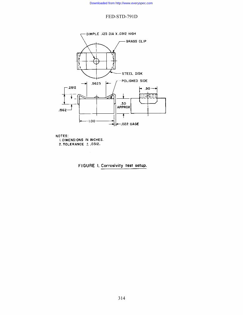
FED-STD-791D
314
Downloaded from http://www.everyspec.com
FED-STD-791D
Method 5329.2 September 30, 1986
CORROSION-PROTECTION (HUMIDITY CABINET) 1. SCOPE
1.1 This method is used for determining the effectiveness of corrosion-inhibiting oils and compounds under conditions of high humidity. 2. SUMMARY
2.1 The test consists of dipping steel test panels in the test sample and then placing them in a humidity cabinet. After the specified exposure time the panels are removed and examined for the presence of rust. 3. SAMPLE SIZE
3.1 Approximately 500 mL of the oil to be tested. 4. REFERENCES, STANDARDS, AND APPARATUS
4.1 Standards. 4.1.1 ASTM D 1748 Rust Protection By Metal Preservatives In the Humidity
Cabinet. 4.2 Humidity cabinet conforming to ppendix I of ASTM D 1748 where the
following standard conditions must be maintained.
a. Air temperature: Inside the cabinet: 49° 1°C (120° 2°F). Outside the cabinet: 24° 5°C (75° 10°F).
b. Rate of air to the cabinet: 868 28 L (31 1 ft3) per hour at 25°C (77°F) and 76 cm of mercury.
c. Water in cabinet: Level - 20.3 0.6 cm (8 1/4 in) pH - 5.5. to 7.5 Oil content - clear with no evidence of oil Chlorides - less than 20 ppm Sulfates & sulfites - less than 20 ppm.
d. Speed of rotating stage - 0.33 0.03 rpm. e. Cover - close fitting. f. Cloth layers in cover - shall not be torn, contaminated, nor contain droplets of
water.
A
315
Downloaded from http://www.everyspec.com
FED-STD-791D
g
and again for 5 m ld elapse between openings.)
i. Check r level and regulate, if necessary, in the morning and afternoon of each day.
eck remaining standard conditions once each week.
4.4 Panel hook, stainless steel (for handling panels during processing).
4.5 Hooks, Monel or stainless steel (for supporting steel panels).
4.7 Beakers, tall-form, 500 mL.
4.8 Controlled atmosphere (to provide a temperature of 25° 3°C [77° 5°F]
lluminator type that ill per viewed from all angles at a distance of 7.6 cm [3
in]).
chemic od ference which lists all toxic and
azard s, life hazard, flammability, handl tions, emergency treatment and measures, and spill practices of each c
(O-M-232) [1,3,0].
5.4 Silica sand, white, dry, sharp. (The size shall be such that it meets the
followin
a. . 20 sieve.
. Cover opening - to a height of 35.6 cm (14 in) at the front. h. Open the cabinet twice each day, except Saturday and Sunday, once for 15 min
in. (A period of approximately 5 h shou
the rate of air to the cabinet, air temperatures, pH, and wate
j. Ch
4.3 Desiccator, containing an indicating desiccant.
4.6 Sandblast cabinet (a suitable apparatus for sandblasting test panels).
and a maximum relative humidity of 50%). 4.9 Shaded fluorescent light. (A 15-watt balance i
w mit the panel to be
5. MATERIALS
5.1 CAUTION: SOME MATERIALS ARE TOXIC AND HAZARDOUS. The al materials listed in this section must be handled carefully. Federal Test Meth
10000, Material Handling Safety Precautions, is a reh ous materials cited in FTMS 791. The synonym
ing and storage precauhemical are explained.
5.2 Naphtha, aliphatic (TT-N-95) [1,4,0].
5.3 Methyl alcohol
g sieve requirements of ASTM E 11.)
100% must pass through a No. 10 sieveb. Minimum of 90% must pass through a No.
mitted to pass through a No. 50 sieve. c. Maximum of 10% per
316
Downloaded from http://www.everyspec.com

FED-STD-791D
5.5 Test panels, FS 1009 steel, fabricated from open-hearth, "killed" type low carboDimensi bar stock is not satisfactory.
5 . PROCEDURE
.1 Clean the steel panels as follows:
a Round the edges and ream out the suspension holes in accordance with
b Wipe the surfaces with solvent soaked rags and scrub with surgical swabs in a
NOT
n, No. 4 soft-temper, cold-rolled sheet or strip conforming to QQ-S-698. ons of the panels shall conform to Appendix I of ASTM D 1748. Cold drawn
.6 Surgical gauze.
6
6
. Appendix I of ASTM D 1748.
. beaker of hot naphtha.
E 1: Caution. Naphtha is flammable. Use only in a well ventilated area. Keep all flames away from the naphtha.
NOT
c. Rinse in a beaker of hot methyl alcohol.
E 2: Caution. Methyl alcohol is both toxic and flammable. Use only ventilated area. Do not allow it to come in contact with the skin or breits fumes. Keep all flames away from methanol.
in a well athe
anels in a desiccator until further processing. a panel hook at all times, avoiding contact
ly sandblast the back of the panels with silica sand. b rface, of the panels to a fresh,
c
d
e Remove remaining residue by holding the panels in a rack at 20° from the htha.
the test surface again. ore in a desiccator
until cool. h. Panels are to be used the same day as prepared.
d. Cool the pe. Test panels must be handled with
with any type of contaminated surface. f. Maintain the solvents at a temperature high enough to keep the temperature of
the panels above the dew point during the cleaning operation.
6.2 Sandblast the panels as follows:
a Sandblast the edges and light. . Sandblast the unnumbered side, or test su
uniformly abraded surface. . Immediately after sandblasting, place the panels in a beaker of anhydrous
methanol. . Heat the methyl alcohol so that the solvent will evaporate from the panels
immediately upon withdrawal from the solvent. .
vertical and spraying downward with napf. Spray the test surface, then the back of the panel and g. Rinse the panels in hot naphtha and hot methyl alcohol and st
317
Downloaded from http://www.everyspec.com
FED-STD-791D
6
r one minute.
b. Suspend the panels by means of Monel or stainless steel hooks and drain for 2 h 5°F) and a maximum of 50 percent relative humidity.
umidity cabinet described in Appendix I of ASTM D e time required by the applicable specification.
d. Dummy panels, fabricated from monel or stainless steel, are used to fill all hey are also placed under the three arm
alcohAppendix I of ASTM D 1748, using a 15-watt,
a sc
ULA
t procedure.
8. N
8.1 Re
. PREC
loped for this method.
.3 Three test panels are processed as follows:
a. Dip the test panels in the test sample at a temperature of 25° 3°C (77° 5°F)and agitate gently fo
at 25° 3°C (77° c. Place the panels in the h
1748 for th
spaces not occupied by test panels. Tsupports of the rotating stage.
6.4 At the end of the exposure period, remove the panels and rinse in methyl ol. Follow with a rinse in naphtha and methyl alcohol and examine the significant
area of the test surface as defined in sh ded fluore ent light.
TIONS 7. CALC
7.1 This section is not applicable to the tes
REPORTI G
cord the extent of corrosion as follows:
a. The number of rust dots, 0.1 cm in diameter or less. b. The number of rust spots, 0.1 to 0.2 cm in diameter.
The number of rust areas, greater than 0c. .2 cm in diameter.
ISION 9
9.1 Precision data have not been deve
Method Prepared by:
Army - AR - 1986
318
Downloaded from http://www.everyspec.com

FED-STD-791D
Method 5331.1 September 30, 1986
1. SC
1 ry, solid-filmnvironm
ray and drying. After each cycle of salt spray and drying, for evidence of corrosion.
3. SAM
L of solid-film lubricant of a sprayable consistency.
. REF S
(10 to 15 psig).
mL/s (1 ft3/min).
y Nozzle (Figure 1) - corrosion resistant with a 13 cm (5 in) diameter ich prevents direct impingement of the spray, but allows a fine mist full
t
4.4 Turntable Assembly which consists of:
a. Turntable - corrosion resistant, 26.7 cm diameter with hoholders and specimens.
b. Driving Mechanism - capable of mechanically rotating turntan electric motor (slow speed), encased within a protective acrymounted above jar on an arrangement of flexaframe support rods.
4.5 Specimen Holders - holder cap (Figure 2) and ice jacket (aluminum) that is so
placed as to be in direct contact with back of test specimen. 4.6 Jar - 30.5 cm I.D. and 30.5 cm high.
CORROSION PROTECTION OF STEEL AGAINST SULFUROUS ACID- SALT SPRAY BY SOLID FILM LUBRICANTS
OPE
.1 This method is used to evaluate the corrosion preventive properties of d lubricant under the combined conditions of salt, sulfurous acid, and humidity ent. e
2. SUMMARY
2.1 A steel disk having solid film lubricant deposited on one surface is subjected the cycling effect of salt spto
the disks are examined
PLE SIZE
3.1 180 m 4 ERENCES, STANDARDS, AND APPARATU
4.1 Air Supply - filtered, 69 gage kPa to 103 gage kPa 4.2 Air flow regulator - capable of regulating air flow at 472 4.3 Spra
crylic baffle whacontac with the disks.
les for mounting test
able at 1/3 rpm by lic box and
319
Downloaded from http://www.everyspec.com

FED-STD-791D
4.7 Support Rods - flexaframe or equivalent. 4.8 Flexible Tygon Tubing - 0.96 cm I.D.
5. MA
5.1 CAUTION: SOME MATERIALS ARE TOXIC AND HAZARDOUS. The terials listed in this section must be handled carefully. Federal Test Method
0000, Material Handling Safety Precautions, is a reference which lists all toxic and hazardo
al are explained.
Specimen - disk with 5.4 cm diameter and thickness of 0.16 cm, made f carbon steel conforming to FS 1010 with a 0.08 cm hole for handling disk with wire.
ith 2 mL sulfurous acid [not less than .0% assay as S02]).
5.4 Aluminum Oxide Cloth - 240 grit.
5.5 1,1,1-Trichloroethane (MIL-T-81533) [2,1,0].
5.6 Distilled Water (ASTM D 1193 - Type III).
.7 Sulfurous acid, ACS [u,u,u].
6. PROCEDURES
a. Degrease test specimens in 1,1,1-trichloroethane (MIL-T-81533). b rit aluminum oxide cloth
to a surface finish of (0.25 to 0.50 µm).
d. and store in a dust-free container.
n requirements.
f.
TERIALS
chemical ma1
us materials cited in FTMS 791. The synonyms, life hazard, flammability, handling and storage precautions, emergency treatment and measures, and spill practices of each chemic
5.2 Steelo
5.3 Synthetic Sea Water-Sulfurous Acid Test Solution - synthetic sea water
(Formula ASTM D 1141 - 41.95 g/L, 900 mL w6
5
6.1 Prepare test specimens as follows:
. Hand polish surface to be tested with 240 g
c. Repeat step (a). Allow specimens to dry
e. Apply solid-film lubricant to surface of steel specimen by spraying to produce a film thickness between 0.0005-0.0013 cm (0.0002-0.0005 in) and cure film in accordance with specificatio
Handle the specimen at all times with a hook.
320
Downloaded from http://www.everyspec.com
FED-STD-791D
6.2 Prepare the apparatus (Figure 3) as follows: a sea water-sulfurous acid solution and
then lower the turntable assembly into jar. in specimen holder (Figure 2) with ice jacket on top.
c. Mount the complete specimen assembly in one of the holes of the turntable and
s:
ae
the turntable above the jar to allow specimens to dry for two hours at room
t specimens after each full cycle, while still retained in the holder, with distilled water (ASTM D 1193 - Type III) and dry with a stream of air.
d dence of visible corrosion, pitting or staining.
e e is defined as the first visible sign of corrosion, pitting or staining.
7. CALCULATIONS
.1 This section is not applicable to the test procedure.
. REPORTING
8.1 Report the number of test cycles completed prior to failure. Report the amou 9. PREC
epared by:
Navy - NADC - 1986
. Fill bottom 5 cm of jar with the synthetic
b. Place disk
start the turntable. d. Turn on the air and regulate rate of flow to 472 mL/s (1 ft3/min). e. Two min after the spray has started, place ice in ice jackets in order to cause a
fine condensate to form on the surfaces of disks.
6.3 Perform test as follow
. Continue spraying for 2 h with a rate of flow of approximately 0.4 mL/s. b. Discontinue the spray at the end of two hours; remove the ice jackets; and rais
temperature. The two-hour spray and two-hour drying period shall constitute one cycle.
c. Rinse the tes
. After each cycle examine test specimen for evi
. Repeat the test cycle until failure occurs. Failur
7 8
nt and type of corrosion present.
ISION
9.1 Precision data have not been developed for this method.
Method Pr
321
Downloaded from http://www.everyspec.com

FED-STD-791D
Method 5414.4 September 30, 1986
E TO FUEL
1. SCOP
action of
2. SUM
rd test fluid, 3. SAM
4. RE
tubes) ap
RESISTANCE OF GREAS
E
1.1 This method is used for determining the resistance of grease to the solvent fuel.
MARY
2.1 The test consists of determining the solubility of the grease in a standa
and observing for physical changes caused by an 8-hour immersion in the test fluid.
PLE SIZE
3.1 Approximately 4 g of grease to be tested (duplicate 2 g samples).
FERENCE, STANDARDS, AND APPARATUS
4.1 Centrifuge, approximately 650 rpm, swing diameter (tip to tip of whirling proximately 40 cm, or equivalent.
NOTE: An equivalent centrifuge must be capable of having its speed adjusted
according to the following formula:
r (tip to tip) of whirling tubes centimeters
(1-1/2 in), speed pproximately 1350 rpm.
4.3 Centrifuge tube, 200 mL, with stopper. 4.4 Evaporation dish, 100 mL. 4.5 Pipet, 50 mL.
650 * d40 = rpm
where: d = diamete
4.2 Shaker, mechanical, stroke approximately 3.8 cm
a
322
Downloaded from http://www.everyspec.com

FED-STD-791D
4.6 g, with stopper.
4.7 Steam bath ( 4.8 Oven, approximately 100°C (212°F).
4.9 Balance, sensitivity 0.2 mg.
on type spatula.
0000, Material Handling Safety Precautions, is a reference which lists all toxic and cited in FTMS 791. The synonyms, life hazard, flammability,
andling and storage precautions, emergency treatment and measures, and spill practices of each
.
. PROCEDURE
6.1 e in the standard test fluid as follows:
a. Clean, dry and weigh a centrifuge tube to within 0.2 mg accuracy. With a spoon spatula spread approximately two g of grease in a thin film inside the tube and weigh to within 0.2 mg; add 100 mL st fluid and stopper the tube.
b. Using the mechanical shaker, shake tube until sample appears to be thoroughly rsed (approximately 1/2 h).
mpletely separated, and the
dhe clear fluid from the centrifuge tube into evaporating dish.
Place dish on steam bath until liquid is evaporated. Then dry dish in oven for
f. After drying, remove dish from oven and reweigh to within 0.2 mg. Determine culate the percent of sample soluble in test fluid
(see 7.1).
6.2 Determine the deterioration of the sample due to the test fluid as follows:
Test tube, approximately 1.5-cm (1/2-in) O.D. by 7.5 cm (3 in) lon
to accommodate evaporating dish).
4.10 Spo
5. MATERIALS
5.1 CAUTION: SOME MATERIALS ARE TOXIC AND HAZARDOUS. The chemical materials listed in this section must be handled carefully. Federal Test Method 1hazardous materialsh
chemical are explained.
5.2 Standard Test fluid (ASTM D 471, Type III)
5.3 Aluminum strip (ASTM B 209), 5.08 � 1.3 � 0.04 cm.
6
Determine the solubility of the sampl
of the te
dispec. Centrifuge the tube until fluid and sample are co
fluid portion is clear and transparent. . Weigh evaporating dish to within 0.2 mg.
e. Pipet 50 mL of t
1/2 h at approximately 100°C.
the weight of residue, and cal
323
Downloaded from http://www.everyspec.com

FED-STD-791D
ainum strip, and place the strip in the test
tube so that it is half immersed in the test fluid. Stopper test tube, and allow it to °C).
b After 8 h, remove strip from test tube (being careful not to disturb sample), and sample while wet for swelling, loss of
adhesion, blistering, cracking, or deterioration, and report observations. c room temperature (approximately 25°C), then
re-examine the sample for the signs of deterioration, and report observations. . CALCULATIONS
7.1 Calculate the percent of sample soluble in test fluid as follows:
where: A = weight of sa B =
9 PREC
Method prepared by:
. Fill test tube to a depth of approximately 2.5 cm with test fluid. Spread the grease evenly on both sides of the alum
stand for 8 h at room temperature (approximately 25.
dip once into fresh test fluid. Examine
. Allow strip to dry for 24 h at
7
BA 200 =y solubilitPercent
mple, mg (see 6.1 f). weight of original sample, mg.
8. REPORTING
8.1 Report percent solubility as determined under 6.1 f.
8.2 Report condition of grease on strip as determined under 6.2. b and c.
ISION
9.1 Precision data have not be developed for this method.
Navy - NADC - 1986
324
Downloaded from http://www.everyspec.com
FED-STD-791D
1. SC
1.1 This method is used for determining the resistance of a grease to the solvent
2. SUM
2.1 The test consists of storing two portions of grease, one in distilled water and the other in an ethyl alcohol-water solution, for one week, and examining the grease for disintegration. . SAMPLE SIZE
ately 4 g of grease to be tested. 4. APPARATUS
ners (2), glass, 250 mL, with stoppers.
. MA
S. The chemical materials listed in
Handling Safety Precautions, is a reference which lists all toxic and S 791. The synonyms, life hazard, flammability,
andlin res, and spill practices f each
5.2 Alcohol, Ethyl, Specially Denatured, Aircraft (A-A-51693). 5.3 Distilled water.
6. PROCEDURE
6.1 Place 200 mL of distilled water into one container, and 200 mL of an alcohol-distilled water solution (1:1 by volume) into the other.
6.2 Place a single globule of grease (approx. 2 g) into each of the two containers,
stopper the containers tightly, and allow both to stand for one week.
Method 5415.1 September 30, 1944
RESISTANCE OF GREASE TO WATER AND A 1:1 WATER-ETHANOL SOLUTION
OPE
action of water.
MARY
3
3.1 Approxim
REFERENCES, STANDARDS, AND
4.1 Contai 5 TERIALS
5.1 CAUTION: SOME MATERIALS ARE TOXIC AND HAZARDOUthis section must be handled carefully. Federal Test Method
10000, Materialazardous materials cited in FTMh
h g and storage precautions, emergency treatment and measu chemical are explained. o
325
Downloaded from http://www.everyspec.com
FED-STD-791D
6.3 At the end of one week, shake ch c taine nce wice, and then visuea on r o or t ally ration.
. CALCULATIONS
7.1 This section is not applicable to the test procedure.
ING
. PRECISION
9.1 Precision data have not been developed for this method.
Method Prepared by:
Navy - NADC - 1986
examine each portion of grease for disinteg
7
8. REPORT
8.1 Report the degree of disintegration of the grease in each container. 9
326
Downloaded from http://www.everyspec.com
FED-STD-791D
September 30, 1986
NITRATE-TYPE IGNITION IMPROVERS IN DIESEL FUEL . SCOPE
1.1 This method of test covers the determination of organic nitrate ester-type cetane t for those iesel fuel inspection test procedures that are affected by the presence of cetane
ly, ASTM D 524 Standard Method of Test for Ramsbottom Carbon esidue of Petroleum Products and D 976 Standard Methods for Calculated Cetane Index
of Disti
. SUMMARY
2.1 A diesel fuel sample is saponified in a potassium hydroxide-1-butanol mixture and then filtered through a glass fiber filter disk. The material remaining on thedisc is treated with diphenylamine reagent after drying. The preseetane improver is revealed by the formation of a blue ring or blue-black spot due to xidation of diplenylamine to intense blue quinoidal compounds by the nitrate salt. No olor change confirms the absence of a cetane improver.
3. SAMPLE SIZE
3.1 A 10-mL sample of diesel fuel is required. 4. REFERENCES, STANDARDS, AND APPARATUS.
4.1 Reaction bottle - screw-cap bottle, 29.6 mL (l fl oz) capacity, wide mouth, flint glass, with screw-cap lined with tin or tetrafluoroethylene (TFE) resin.
4.2 Glass fiber filter paper - 3.7 cm diameter, Grade 934 AH (H. Reeve Angel,
Inc., Clifton, NJ, or equivalent). 4.3 Pipette - 10 mL capacity, fitted with pipetting bulb. Several types and makes
of pipetting bulbs and assemblies are available. One of the following is suggested: Fisher Cat. No. 13-681, Safety Pipet Filler, or equal; Fisher Cat. No. 13-681-50, Pipet Filler, or equal.
4.4 Graduated cylinders - 10 and 25 mL capacity. 4.5 Suction flask with a suitable holder to accommodate a 60-mL glass-fritted
crucible.
Method 6050.1
1
improver additives used in diesel fuel. It is intended as a screening tesdimprovers; nameR
llate Fuels. 2
nce of a nitrate ester
coc
327
Downloaded from http://www.everyspec.com

FED-STD-791D
4.6 Crucible - 60 mL capacity, glass-fritted, med porosity. ium
4.7 Oven suitable for drying filter discs at 110°C. 5. MATERI
CAUTION: SOME MATERIALS ARE TOXIC AND HAZARDOUS. The hemical materials listed in this section must be handled carefully. Federal Test Method
10000,
ication Mixture (lN) - Prepared by mixing 6.5 g potassium hydroxide CS grade) [3,0,1] with 100 mL absolute n-butyl alcohol (ACS grade) [1,3,0] and
e the KOH. After the solution cools, the mixture is filtered through the lass fiber filter paper.
NOTE 1:
ALS
5.1 c
Material Handling Safety Precautions, is a reference which lists all toxic and hazardous materials cited in FTMS 791. The synonyms, life hazard, flammability, handling and storage precautions, emergency treatment and measures, and spill practices of each chemical are explained.
5.2 Saponif
(Aheating to dissolvg
5.3 Diphenylamine (1%) Solution - Prepared by dissolving 0.250 g
diphenylamine (ACS indicator grade) [3,1,0] in 25 mL sulfuric acid (sp gr 1.834) [3,0,2]. 5.4 Toluene (ACS Reagent grade) [2,3,0].
Toluene is flammable and toxic. Avoid breathing vapors or contact with
6. PRO
ttle and add 5 mL of toluene llowed by 10 mL of the saponification mixture.
skin.
CEDURE
6.1 Pipette 10 mL of sample into the reaction bofo
NOTE 2: Oral pipetting techniques should not be used because of the toxicity of the substances involved. A pipetting bulb or assembly similar to one of those
.2 Affix cap to the reaction bottle tightly and, after mixing the contents, place it in an ov
e 60-mL glass-fritted crucibl
ed crucible.
described in 4.3 should be used.
6en maintained at 110°C for 4 h. 6.3 Remove the reaction bottle from the oven and allow it to cool to 25° 3°C. 6.4 Filter the contents of the reaction bottle through the fitted with the glass fiber filter disc. 6.5 Wash the reaction bottle with 25 mL of toluene and transfer it to the
glass-fritt
328
Downloaded from http://www.everyspec.com

FED-STD-791D
6.6 Carefully remove the glass fiber filter disc and dry it in oven at 110°C for 15 min.
6.7 Remove the filter disc and cool it to 25° 3°C.
6.8 Add 3 drops of diphenylamine solution to the center of the disc and observe whethe
8. REPORTING
f the approved cetane improvers (amyl nitrate, cyclohexyl nitrate, hexyl nitrate and isopropyl nitrate) give an intense blue to blue-black color throughout the rea
blue-black coloration), the carbon residue determination (ASTM D524) must be perform
9.
9.1 Precision data have not been developed for this method.
Army - ME - 1986
r a blue or blue-black color forms.
7. CALCULATIONS
7.1 This section is not applicable to the test procedure.
8.1 The presence of organic nitrate ester-type cetane improvers will be reported if the formation of a blue color occurs. Reference samples of diesel fuels containing 0.5% by volume of any one o
gent spot whereas those samples containing only 0.1% by volume produce a blue ring at the outer boundary of the reagent. If a positive reaction occurs (i.e., a blue or
ed on a neat or base fuel blend.
PRECISION
Method Prepared by:
329
Downloaded from http://www.everyspec.com

FED-STD-791D
September 30, 1986
RAY IGNITION
1. SCO
.1 This method is used for determining the relative flammability of liquids.
. SUMMARY
2.1 The method consists of forcing the test fluid sample through a 0.0368-cm at 6.98 MPa gage (1000 psig), attempting to ignite the spray with a
rch and noting the characteristics of the resulting flame.
ray test setup. A setup similar to Figure 1 shall be assembled so as to
pply a constant pressure of 6984 " 69 kPa gage (1000 " 10 psig) to the sample.
4.1.2 Torch. An oxyacetylene torch equipped with a No. 3 tip or equal. 4.1.3 Nozzle. A nozzle 0.163-cm (0.064-in) thick by
minimum diameter with a centered orifice approximately 0.0368-cm (0.0145-in) diameterhaving sharp, square edges (see Figure 1).
. MATERIALS
5.1 CAUTION: SOME MATERIALS ARE TOXIC AND HAZARDOUS. The chemical materials listed in this section must be handled carefully. Federal Test Method 10000, Material Handling Safety Precautions, is a reference which lists all toxic and hazardous materials cited in FTMS 791. The synonyms, life hazard, flammability, handling and storage precautions, emergency treatment and measures, and spill practices of each chemical are explained.
5.2 Nitrogen. A cylinder of nitrogen fitted with a regulator capable of supplying
6890 kPa gage (1000 " 10 psig) of pressure to the system.
Method 6052.1
HIGH-TEMPERATURE--HIGH-PRESSURE SP
PE
1 2
(0.0145-in) orificeto
3. SAMPLE SIZE
3.1 Sufficient liquid to be tested to fill cylinder of spray test setup. 4. REFERENCES, STANDARDS AND APPARATUS
4.1 Apparatus.
4.1.1 Spsu
0.965-cm (0.38-in)
5
330
Downloaded from http://www.everyspec.com

FED-STD-791D
6. PROCEDURE
6.1 Fill the fluid cylinder of the spray test setup with test fluid at 15.6° to 37.8°C (60° to 100 94 " kPa
10 psig).
ifice and attempt to ignite the spray the nozzle.
ignites. If the spray does ignite, also report:
a
9. PRE
Method Prepared By:
°F) and adjust nitrogen pressure to produce a liquid pressure of 68gage (1000 "
6.2 Adjust the torch to deliver a neutral flame. 6.3 Open the quick-opening valve at the or
with the torch at 6.4 If the spray does not ignite gradually move the torch away from the nozzle
until ignition takes place (45.7 cm max.) 7. CALCULATIONS
7.1 This section is not applicable to the test procedure. 8. REPORTING
8.1 Report whether the spray
. The distance from torch to nozzle at ignition. b. Whether the spray flashes readily or with difficulty. c. Whether the flame produced is self extinguishing or sustained.
CISION
9.1 Precision data have not been developed for this method.
Army - ME - 1986
331
Downloaded from http://www.everyspec.com
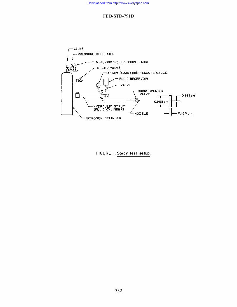
FED-STD-791D
332
Downloaded from http://www.everyspec.com
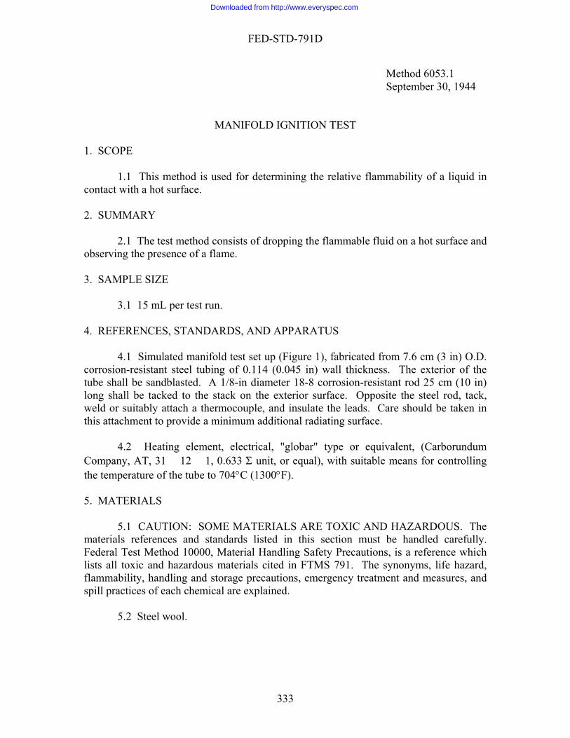
FED-STD-791D
333
eld or suitably attach a thermocouple, and insulate the leads. Care should be taken in is attachment to provide a minimum additional radiating surface.
4.2 Heating element, electrical, "globar" type or equivalent, (Carborundum
ompany, AT, 31 � 12 � 1, 0.633 Σ unit, or equal), with suitable means for controlling e temperature of the tube to 704°C (1300°F).
. MATERIALS
5.1 CAUTION: SOME MATERIALS ARE TOXIC AND HAZARDOUS. The aterials references and standards listed in this section must be handled carefully. ederal Test Method 10000, Material Handling Safety Precautions, is a reference which sts all toxic and hazardous materials cited in FTMS 791. The synonyms, life hazard, ammability, handling and storage precautions, emergency treatment and measures, and ill practices of each chemical are explained.
5.2 Steel wool.
Method 6053.1 September 30, 1944
MANIFOLD IGNITION TEST
1. SCOPE
1.1 This method is used for determining the relative flammability of a liquid in contact with a hot surface. 2. SUMMARY
2.1 The test method consists of dropping the flammable fluid on a hot surface and observing the presence of a flame. 3. SAMPLE SIZE
3.1 15 mL per test run. 4. REFERENCES, STANDARDS, AND APPARATUS
4.1 Simulated manifold test set up (Figure 1), fabricated from 7.6 cm (3 in) O.D. corrosion-resistant steel tubing of 0.114 (0.045 in) wall thickness. The exterior of the tube shall be sandblasted. A 1/8-in diameter 18-8 corrosion-resistant rod 25 cm (10 in) long shall be tacked to the stack on the exterior surface. Opposite the steel rod, tack, wth
Cth 5
mFliflsp
Downloaded from http://www.everyspec.com
FED-STD-791D
6. PROCEDURE
6.1 Clean the outside surface of the tube of the test setup (Figure 1), using steel ool.
6.2 Mount the heating element centrally in the tube, and adjust the voltage so that
ure of the tube is maintained at 704°C (1300°F).
mL in 40 to 60 s from various heights onto various points on e tube, and observe the ignition characteristics of the liquid. (Clean the tube with steel
10 mL application of the liquid.)
7. CAL
7.1 This section is not applicable to the test procedure.
. REPORTING
8.1 Report results as follows:
a. Flashes or burns on the tube, but does not after dripping from the tube. b
Method prepared by:
Army - ME - 1986
w
the temperat
6.3 When the tube has reached the correct temperature, drop 10 mL portions of the test liquid at a rate of 10thwool before each
CULATIONS
8
. Does not flash or burn on tube, but does after dripping from the tube. c. Does not flash or burn on the tube or after dripping from the tube.
9. PRECISION
9.1 Precision data have not been developed for this method.
334
Downloaded from http://www.everyspec.com
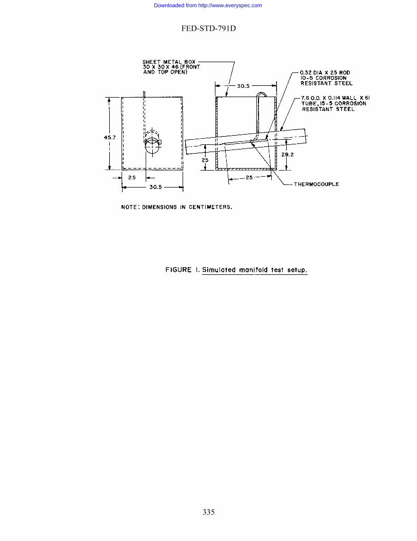
FED-STD-791D
335
Downloaded from http://www.everyspec.com

FED-STD-791D
Method 6508.2 September 30, 1944
LOAD CARRYING CAPACITY OF LUBRICATING OILS (Ryder Gear Machine)
1. SCOPE
1.1 This method describes a procedure for determining the load carrying ability of lubricating oils with reference to gears.
2. SUMMARY
2.1 The test consists of incremental increasing the pressure between gears to measure the resultant scuffing. The ability of the test oil to impair scuffing is measured by the maximum pressure when operating at 10,000 rpm.
3. SAMPLE SIZE
3.1 Approximately 2 L of test oil. 4. REFERENCES, STANDARDS, AND APPARATUS
4.1 Test unit. The apparatus used in this method is the Ryder gear-Erdco universal tester (Figure l), and test gears available from Erdco Engineering Corp., Addison, Ill. This tester comprises a special test machine known as the Ryder gear
achine, a drive system, a support and load oil system, a test oil system, and the ecessary instruments and controls. Figure 2 illustrates the control console.
4.1.1 Ryder gear machine. The Ryder gear machine operates on the so called
our square" principle. As shown in Figure 3, two parallel shafts (P and Q) are onnected by two slave gears (R and S) and two test gears (T and U) to form a "square", that the power required to operate the machine is only that required to overcome the iction losses in the gear and bearings. The slave gears are helical gears made integral to e shafts, (see Figure 4). The replaceable test gears are spur gears, shown installed on e shaft in Figure 5. Load on the test gears is obtained through the application of a
ontrolled oil pressure in two load chambers (Figure 3, Y and Z) which causes an axial ovement of one shaft relative to the other. Because of the integral helical slave gears, a rsional load is thus applied on the shafts thereby loading the test gears. The relation
etween the tooth load on the test gears and the load oil pressure is obtained by arithmetic alculation, calibration, or both. Arithmetic calculation is used herein.
4.1.2 Test gears. The test gears are special spur gears, made of AMS 6260 steel,
ase hardened and ground, having 28 teeth, 8.88-cm (3.5-in) pitch diameter, 8 diametral pitch, 22.5° pressure angle, and zero tip relief. Each set of test gears comprises gears of
mn
"fcsofrththcmtobc
c
336
Downloaded from http://www.everyspec.com

FED-STD-791D
two different widths. The narrow test gear is used for rating purposes. The mating gear
oth loads. Both sides of the test gear are used for testing. The "A" side of the gear fers to the side obtained by installing the tests gears with the serial numbers facing the
end cover as s ar (serial numbers facing away from the en be used once only on each side and then discarded.
4.1.3 Support and load-oil system. The support and load-oil system, shown in Figure
is charged with approximately 30 L (8 gal) of lubricating oil, SAE J1966. It is recommended that the oil be changed every 200 h of running time under normal circumstances. A support oil pressure pump and a relief valve furnish oil to the distributing manifold at a specified support oil pressure of 758 69 gage kP ing
fter the pump, through the action of therm om the distributing manifold lubricate the bearings and helical gears of the machine as well as the adapter housing and the stepup gear box. T to 172 to 207 kPa gage (25 to 30 psig) by a thro tle enge oil from the machine, the adapter housing, and the step-up gear box, back to th e action of the load oil uting manifold (Figure 6) enters the R
a
bers. through
pressure gages (a low range and a high range) located ne
ed by a thermo switch
is wider in order to maintain a constant contact width between the two gears at different tore
hown in Figure 5. The "B" side is obtained by reversing the ged cover). Test gears can
6, serves two purposes: to provide lubrication to all parts except the test gears andto apply load to the test gears. The system
a (110 10 psig). The support oil temperature, also measured at the distributmanifold, is maintained at a specified value of 73.9° 2.5°C (165° 5°F) by electric heaters located in the sump and by a water cooler located a
oswitches. Pressure lines fr
he pressure to the latter is reduced valve. Three scavenge pumps scavt
e support oil sump. Thcircuit can be seen in Figures 3 and 6. Oil from the distrib
yder gear machine at points W and X (Figures 3 and 6). After lubricating the bearings and slave gears, the oil enters the load chambers Y and Z (Figure 3). Forgiven pressure in the distributing manifold, the pressure in the load chambers is dependent on the flow restriction offered by the circuit downstream of the load chamFigure 6 shows that the oil, upon leaving the load chambers at J and J, must pass a control in the load oil circuit before returning to the support oil sump. Two
ar the outlet points J and J, read the so called "load oil pressure", i.e. the pressure in the load chambers. The load oil circuit contains three valves. Of these the load bypass valve is an open or shut valve which is closed during the test run. The load oil pressure is controlled by regulating the load oil adjusting valve. The bleeder valve is normally slightly open, its function being to decrease the sensitivity of the load adjusting valve, thus facilitating the control of load oil pressure. The load bypass valve is opened when it is desired to quickly release the load on pressure, such as at the end of a test run.
4.1.4 Test oil system. A schematic diagram of the test oil system is shown in
Figure 7. The capacity is 500 mL. Test oil is supplied to the test gears by a pressure pump through a jet located on the unmeshing side of the gears. Oil temperature to test gears is maintained at 73.9° 2.5°C(165° 5°F) by a line heater actuat
and controlled by a thermocouple close to the oil jet. The bypass circuit is arranged to permit the use of the graduated sump for the determination of the test oil flowrate. The bypass circuit also facilitates inspection of the narrow test gear without stopping test oil circulation.
337
Downloaded from http://www.everyspec.com

FED-STD-791D
4.1.5 Drive system. As shown in Figure 1, the Ryder Gear machine (A) is drivenby a 50 hp induction motor (B) through a dynamic coupling (C), a step-up gear box (D), and an adapter (E). The test gear speed is controlled by adjusting the field excitation othe dynamic coupling. By this means, accurate speed control from standstill to well overthe specified test speed of l0,000 rpm can be attained.
4.2 Instrume
f
ntation and controls. All of the instruments and controls that require constant attention during test are located on the control console (Figure 2). Items that do not req
s
t
r g
load oil circuit (Figure 6) only the bleeder valve is d
y is
s
uire frequent attention are located on the test stand. The functions of most of the instruments and controls are apparent. Therefore, only selected items will be explained further.
4.2.1 Speed measurement and control. An electronic counter (Figure 2, item 4),
located on the control panel, measures the speed. This instrument is actuated by pulsesupplied by a variable reluctance pickup (the variable reluctance being provided by a 60-tooth gear operated from the driven shaft of the step-up gear box). The rpm adjustmencontrol (Figure 2, item 20), located on the con-sole, regulates the field excitation of thedynamic coupling and thus the gear speed.
4.2.2 Control of test run duration. An electric timer (Figure 2, item 10) located
on the console, is used to control the duration of each test run. As soon as the desired test load has been reached the timer is started at the determined test duration setting. After the run is over the timer automatically turns off the drive motor and opens the load-bypass valve. The timer switch must be turned to the "stop" position prior to the next run.
4.2.3 Support-oil controls. The support-oil pump buttons (Figure 2, item 11) on
the console are connected to the support-oil pressure pump as well as the three scavenge pumps. Pressing the start or stop button controls all four pumps at the same time. The support-oil heater buttons (Figure 2, item 12) control both the electric heaters and the water cooler through the action of thermoswitches (Figure 6). The support-oil chambevacuum is measured by a water manometer located on the test stand. A valve connectinthe chamber to a vent (Figure 6) should be adjusted to give a chamber vacuum of 2.5 to 10.2 cm (1 to 4 in) of water under normal test conditions. If this value cannot be maintained, the shaft and shaft seals should be inspected for leakage.
4.2.4 Control of load oil pressure. The control of load oil pressure has been
explained in 4.1.3. Of the three valves in the not remote controlled. However, this valve need only be set to give the desire
sensitivity for load control during installation of the tester. As a rule, adjustments are seldom necessary thereafter. The load adjusting valve is air actuated and is controlled bthe load adjust control (Figure 2, item 9) located on the console. The load bypass valvesolenoid actuated and is controlled by the load bypass switch (Figure 2, item 13) on theconsole. During the test run the load bypass switch is in the "close" position and the load bypass valve is closed. At the end of a run, the solenoid circuit will automatically be opened by the electric timer. This opens the load-bypass valve, but the load bypas
338
Downloaded from http://www.everyspec.com

FED-STD-791D
switch
rols except those for instruments. The tim r switch and the load bypass switch remain in the positions to which they were origina
co universal tester. A camera with accessories for photographing the gear teeth is available as optional equipment. To inspect or photograph the narrow test gear the machin
roscope provided with the tester is an 18X stereoscopic microscope. A high intensity light source is provided for use with the microsc
that has
.5 Photographic equipment. This is optional equipment consisting of a Leica camera
a Stop watch for measurement of test oil flow rate. b of
ch
on the console remains in the "close" position. For this reason, the switch should be turned to the "open" position prior to the next run.
4.2.5 Emergency stop. The emergency stop button (Figure 2, item 18) on the
console stops the drive motor and turns off all the conte
lly set. 4.3 Scuff rating equipment. A microscope and a light source for visual
inspection of the narrow test gear are provided as standard equipment with the Ryder gear-Erd
e is stopped, but the test oil is kept circulating through the bypass circuit. The inspection or photographing can then be accomplished through special inspection holes provided in the gear case without taking off the end cover. These holes are closed with corks during the test run.
4.4 Inspection equipment. The mic
ope. Figure 8 shows the inspection equipment in position for use. The left eyepiece of the microscope contains a net reticule which divides the gear tooth area lengthwise into five 20%-sections as shown in Figure 10. These 20% grids provide a convenient means for the visual estimation of the percentage of gear tooth areabeen scuffed. Scuffing of individual gear teeth is estimated to the nearest 5%.
4 with a copying attachment, a viewer, and an electronic flash unit synchronized
with the camera shutter. Figure 9 shows this equipment installed for use. 4.6 Gear tooth indexing rachet. An indexing rachet (Figures 1 and 8) is used to
rotate the test gears so that the teeth of the narrow gear can be brought into position one by one for inspection or photography.
4.7 Additional instruments. . . Micrometer 0. to 2.5 cm (0 to 1 in) for measurement of the gross tooth width
the narrow test gear. c. Set of conventional mechanical tools as necessary for assembly, disassembly,
maintenance and repair.
5. MATERIALS
5.1 CAUTION: SOME MATERIALS ARE TOXIC AND HAZARDOUS. The materials references and standards listed in this section must be handled carefully. Federal Test Method 10000, Material Handling Safety Precautions, is a reference whi
339
Downloaded from http://www.everyspec.com

FED-STD-791D
lists all toxic and hazardous materials cited in FTMS 791. The synonyms, life hazard, flammability, handling and storage precautions, emergency treatment and measures, and spill pr tices of each chemical are explained.
shing solvents.
-
-ring is used between the main case and the end cover of the Ryder gear machine. National No. 622710 O-rings 0.238 � 1.27 � 1.75 cm (3/32 � 1/2 � 11/16 i e
a
8 � 7.30 �
listed in Table I should be controlimits success 5 s. A w test gear the percent of tooth area scuffed.
ac
5.2 Lubricating oil, SAE J1966. 5.3 Flu 5.3.1 Dry cleaning (A-A-59601D). 5.3.2 Petroleum ether (O-E-751) [1,4,0]. 5.4 Test gear retaining nut lock washer, Fafnir WO-6 (Erdco Engineering Corp
oration, Addison, ILL, or any commercial supplier of Fafnir parts). 5.5 O-rings. An O
n) are recommended. It is recommended that a new O-ring be used each time thend cover is installed. These rings can be obtained from Erdco Engineering Corp., Addison, IL, or any commercial supplier of National O-rings.
5.6 Shaft seals. The shaft seals recommended for the Ryder Gear machine are
Garlock seals (obtained from Erdco Engineering Corp., Addison, IL, or the Garlock Packing Co., Palmyra, NY) with the following part numbers and dimensions:
. Klozure 63 � 359 with 9478 element and light-weight spring 2.86 � 5.08 � 0.952 cm (l-1/8 � 2 � 3/8 in).
b. Klozure 63 � 1200 with 9478 element and light-weight spring 5.01.27 cm (2 � 2-7/8 � 1/2 in).
6. PROCEDURE
6.1 Operating condition. 6.1.1 Throughout the entire test, the variables
lled within the limits specified. With the tester operating within the specified , the test gears are loaded first to 34 kPa gage (5 psig) load oil pressure, and then at
e increments of 34 kPiv a (5 psi). The duration of each loading period is 10 min t the end of each loading period, the tester is stopped and each tooth of the narro
is examined to determine
340
Downloaded from http://www.everyspec.com
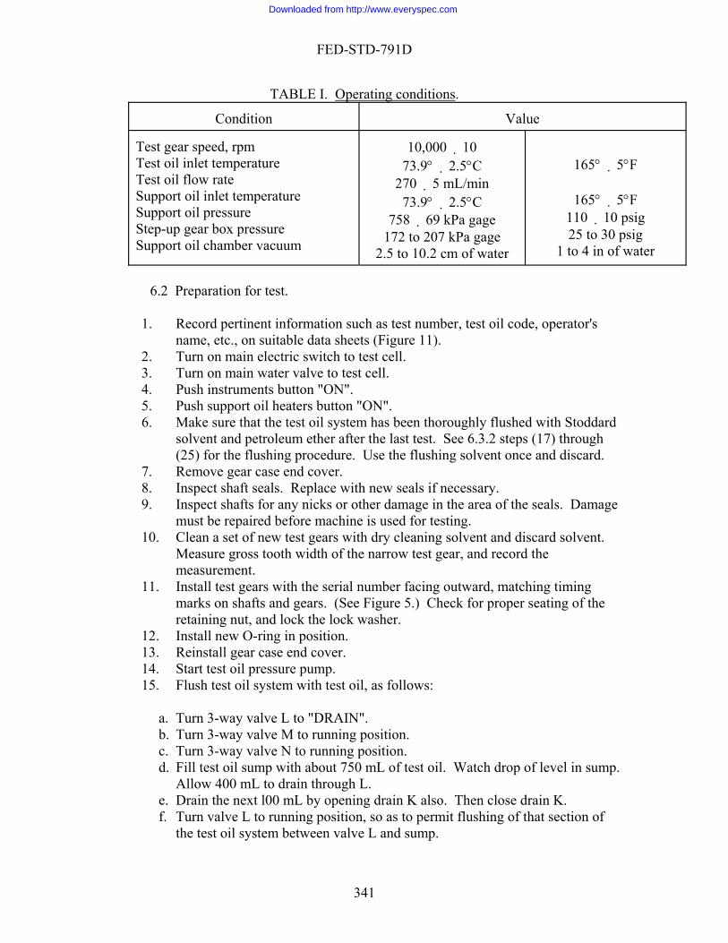
FED-STD-791D
TABLE I. Operating conditions.
Condition
Value Test gear speed, rpm TeTest oil flow rate Su re Support oil pressure StSupport oil chamber vacuum
10,000 10 73.9° 2.5°C
270 5 mL/min 73.9° 2.5°C
758 69 kPa gage 172 to 207 kPa gage
to 10.2 cm of water
165° 5°F
165° 5°F 110 10 psig 25 to 30 psig
1 to 4 in of water
st oil inlet temperature
pport oil inlet temperatu
ep-up gear box pressure
2.5
1 Record pertinent information such as test number, test oil code, operator's
6 Make sure that the test oil system has been thoroughly flushed with Stoddard
d.
8. Inspect shaft seals. Replace with new seals if necessary. age
hine is used for testing. .
est gears with the serial number facing outward, matching timing 5.) Check for proper seating of the
the lock washer. 1 osition. 1
d. Fill test oil sump with about 750 mL of test oil. Watch drop of level in sump. Allow 400 mL to drain through L.
e. Drain the next l00 mL by opening drain K also. Then close drain K. f. Turn valve L to running position, so as to permit flushing of that section of
the test oil system between valve L and sump.
6.2 Preparation for test.
. name, etc., on suitable data sheets (Figure 11).
2. Turn on main electric switch to test cell. 3. Turn on main water valve to test cell. 4. Push instruments button "ON". 5. Push support oil heaters button "ON".
. solvent and petroleum ether after the last test. See 6.3.2 steps (17) through (25) for the flushing procedure. Use the flushing solvent once and discar
7. Remove gear case end cover.
9. Inspect shafts for any nicks or other damage in the area of the seals. Dammust be repaired before mac
10. Clean a set of new test gears with dry cleaning solvent and discard solventMeasure gross tooth width of the narrow test gear, and record the measurement.
11. Install tmarks on shafts and gears. (See Figureretaining nut, and lock
. Install new O-ring in p23. Reinstall gear case end cover.
14. Start test oil pressure pump. 15. Flush test oil system with test oil, as follows:
a. Turn 3-way valve L to "DRAIN". b. Turn 3-way valve M to running position. c. Turn 3-way valve N to running position.
341
Downloaded from http://www.everyspec.com
FED-STD-791D
g. Drain the remain bypass the Ryder gear machine, and turning valve N to "DRAIN".
N
ing 250 mL by turning valve M to
OTE 1: The test oil for flushing is to b disca . If the supply test oil is d quantity may be used for flushing.
N to running p
p with a new charge o button "ON".
oil chamber20. Allow at least 20 minutes to elapse ters w
on (step 5). Then start support oil pumps. 2 "STOP" position. 22. Set electric timer to 10 min and 0 s. Then lock timer dial.
24. setting the input sensitivity e selector switch to "ONE
ld read 60. After checking, turn input cale.
sition.
ows:
. e required for 270 mL of
b. able speed transmission to vary the speed of the test oil .
. . NOTE 2:
e rded after uselimited, a reduce
16. Turn valves L, M, and osition. test oil (500 mL17. Fill test oil sum f ).
18. Push test oil heaters19. Close valve to support v
since the support oil heaacuum manometer.
ere turned
1. Turn timer switch to
23. Turn rpm adjust control to "ZERO" position. Check calibration of electronic rpm counter by control to "CHECK" position, and the gatSECOND" position. The counter shousensitivity control to about mids
25. Turn load bypass control to "OPEN" po26. When the test oil and support oil temperature are up to the specified value of
73.9° 2.5°C (165° 5°F), check support oil chamber vacuum 2.5 to 10.2 cm ([1 to 4 in], of water, see 4.2.3).
27. Check test oil flow rate as foll
a Turn 3-way valve L to stop flow from the Ryder gear machine. By noting the drop of oil level in the test oil sump, measure the timtest oil to accumulate in the Ryder gear machine. Then turn valve L back to running position. Adjust the varipressure pump, until the specified flow rate at 270 5 mL/min is obtained
Test procedure. 6.3 6.3 1 Test on "A" side of test gears
The "A" side of the gear refers to the side obtained by installing the test g the end cover. The "B" side is
bers facing away from the end
1.
2.
3. pen (counterclockwise).
gears with the serial numbers facinobtained by reversing thegear (serial numcover).
Check all temperatures and pressures for the specified limits. (See paragraph 3). Recheck test oil flow rate if necessary.
Make sure that the gear-tooth indexing rachet is locked in disengaged position.
Make sure that the load adjust control is wide o
342
Downloaded from http://www.everyspec.com

FED-STD-791D
4. 5. t control clockwise until the
specified 10,000 100 rpm is obtained. Measure speed with the electronic
6. Tu7. Apply load slowly by turning the load adjust control clockwise. Stop when
NOTE 3:
Start drive motor. Increase gear speed by turning the rpm adjus
rpm counter. rn load bypass control to "CLOSE" position.
the load oil pressure is 34 kPa gage (5 psig).
In adjusting load oil pressure, take care not to overshoot the desired
8.
. The 10-minute test run now begins. test run.
er will automatically stop the
s control
heir respective off positions:
. b. c. osition.
12. Make visual scuff inspection of the narrow test gear, as follows:
a. b. c. l from the test gear with compressed air through the
d. e. Focus microscope and adjust the 20% grid lines over the contact area of the
re 10). f. Set indexing ratchet wheel to "No. 1" position.
. l tooth to the nearest 5%, and record the value (See Figure 12).
h. Op ating ste
i. Re croscope and light. Replace corks in the holes. j. Turn 3-way valve M to running position. .
oad
sure.
pressure.
Check gear speed. 9. Turn timer switch to "START" position10. Record all pertinent data about midway into the 10-minute 11. At the end of the l0-minute run, the electric tim
drive motor and open the load bypass valve. However, the timer switch on the control console will remain in "START" position, the load bypaswill remain in "CLOSE" position, and the rpm adjust control will remain in running position. To restore these to t
a Turn load bypass control to "OPEN" position. Turn timer switch to "STOP" position. Turn rpm adjust control to "ZERO" p
Turn 3-way valve M to bypass flow around the Ryder gear machine. Remove corks from inspection holes on the gear case. Blow off excess oiinspection hole. Install microscope and inspection light.
tooth. (See Figu
g. Estimate the percent scuff on No
erate indexing ratchet to give No. 2 tooth, then No. 3 tooth, etc., repep (g) until all 28 teeth have been examined move mi
k Lock indexing ratchet in disengaged position.
13. Repeat steps (3) through (12) at the next test load of l70 kPa (10 psig) loil pres
343
Downloaded from http://www.everyspec.com

FED-STD-791D
14. Continue the test at 34 kPa (5 psi) load oil pressure increments, until the
va e. ent and take a photograph
NOTE 4:
average scuffed area for all 28 teeth is closest to 22.5%. At this juncture, visually estimate the percent effective tooth width to the nearest 1 percent, and record the lu
15. Also at this juncture, install photographic equipmof each gear tooth. Make the first frame a test identification frame.
Step (15) is optional. Photographic records of the scuffed gear teeth are
as supplied (see 4.5), and Plus-X film, the camera should be set at a lens aperture ("f" value) of 16. The actual exposure time is controlled
flash unit; but to insure adequate exposure, the camera
17. 18. 19. 20. Stop test oil pressure pump. 2122
NOTE 5:
not required in current test specifications. Using the photographic equipment
by the electronicspeed should be set at 1/25 s.
16. Further continue the test at 34 kPa (5 psi) load oil pressure increments, until an approximate average scuffed area of 40% or more is obtained. Push test oil heaters button "OFF". Drain all test oil by first opening 3-way valve L and then valves K and N. Close all drains.
. Push support oil heaters button "OFF".
. Stop support oil pumps.
Leave other controls on if test on "B" side will proceed after a short turn off
main electric switch and main water valve to test cell.
6
NOTE 6:
midday break. Otherwise, push instruments button "OFF", and
.3.2 Test on "B" side of test gears.
The "B" side refers to the side obtained by reversing the gear (serial
1. button "ON". 2. 3. 4. h compressed air. 5. Blow out line screen filters with compressed air.
6. oper seating of the retaining
7. 8. 9. Start test oil pressure pump.
numbers away from end cover).
Push support oil heaters Remove gear case end cover. Remove O-ring.
Blow out test oil jet wit Reverse test gears so that the serial numbers face inward, again matching
timing marks on shafts and gears. Check for pr nut, and lock the lock washer. Install new O-ring. Reinstall gear case end cover.
10. Flush test oil system with test oil, in accordance with 6.2, step (15).
344
Downloaded from http://www.everyspec.com
FED-STD-791D
NOTE 7: If the supply of test oil is limited, this flushing between tests on "A" and " gears may be omitted.
Turn valves L, M, and
B" sides of the
11. N to running position. l
13. Allow at least 20 min to elapse since the support oil heaters were turned on
14. Wh alue of 73(1
15. Ch16. Proceed on test on "B" side of the test gears, by following the procedure
outlined in 6.3.1 steps (1) through (18).
. tion. . . L of the solvent. Watch drop of level in
ars by operating the indexing ratchet. Allow
. opening drain K also. Then close drain K. e. Turn valve L to running position, so as to permit flushing of that section of
f. Drma
NOT
12. Fill test oil system with a new charge of test oil (500 mL). Then push test oiheaters button "ON".
(step 1). Then start support oil pumps. en the test oil and support oil temperatures are up to the specified v
.9° 2.5°C (165° 5°F) check support oil chamber vacuum 2.5 to 10.2 cm to 4 in) of water. eck test oil flow rate as described in 6.2, step (27).
17. Flush test oil system with Stoddard solvent, as follows:
a Turn 3-way valve M to running posib Turn 3-way valve N to running position. c Fill test oil sump with about 750 m
sump. Slowly turn the test geabout 400 mL to drain through L.
d Drain the next 100 mL by
the test oil system between valve L and sump. ain the remaining 250 mL by turning valve M to bypass the Ryder gear chine, and turning valve N to "DRAIN".
E 8: The flushing fluid is to be used only once and then discarded.
18. Flush test oil system with petroleum ether, by repeating step (17).
erate test oil pressure pump in reverse for about 60 s, and then resum19. Op e normal rotation. To reverse pump, adjust the variable speed transmission.
d air.
"OFF". Then stop support oil pumps. ton "OFF".
test cell. test cell.
6.3.3 Sequence for repeat test. Repeat test on the same oil may be conducted by
omitting steps (26) through (30) of the sequence for "B" side of the test gears (6.3.2.
20. Stop test oil pressure pump. 21. Remove gear case end cover. 22. Remove O-ring. 23. Remove used test gears. 24. Blow out gear case and test oil jet with compresse25. Blow out line screen filters with compressed air. 26. Reinstall gear-case end cover (without test gears). 27. Push support oil heaters button 28. Push instruments but29. Turn off main electric switch to30. Turn off main water valve to
345
Downloaded from http://www.everyspec.com

FED-STD-791D
Instead, proceed from step (8) of the sequence for preparation (6.2), and continue through the complete test sequence (6.3)).
1. utton.
3. .
5.
6.4. r tooth is that area from which the axial i sion, and wear. As
own in Figure 10, areas A and B are scuffed; area C is not scuffed. Note that only the actual w tooth surface is considered in the definitio
6.4.
portion of t hat has been scuffed. Referring to Figure 10,
Th f e, but at ast to the nearest 5%, for each individual tooth, with the aid of a net reticule mounted in
the ey
6.4.scuffe th rcent of scuffed area of all 28 teeth of the narrow test g st 1%.
actual width of the narro ar gear. To determine the effect oestim e n or with t d and 7.1.
ing ability, or the scuff limited load, f a lub
6.3.4 Emergency stop.
Push emergency stop b2. Push instruments button "OFF".
Turn off main electric switch to test cell4. Turn off main water valve to test cell.
Investigate and take appropriate action.
6.4 Inspection and rating.
1 Scuffed area. The scuffed area of a geagrind ng marks have been removed by scratching, scoring, abra
shorking portion (areas A plus B plus C) of the n of areas.
2 Percent of tooth area scuffed. The percent of tooth area scuffed is that he working surface of a gear tooth t
100 * C+ B+ A
= area working
= scuffedarea tooth Percent B+ A100 * area scuffed
e percent o tooth area scuffed is estimated visually as accurately as possibl
leepiece of the inspection microscope.
3 Average percent of tooth area scuffed. The average percent of tooth area d is e algebraic average of the pe
ear. Calculate this value to the neare 6.4.4 Effective tooth width. The effective tooth width is the
w ge tooth that is in contact with the tooth of the wide ive t oth width, measure the gross tooth width by means of a micrometer, and ate th ratio of effective tooth width to gross tooth width by visual examinatiohe ai of a suitable scale, referring to Figure 10,
6.4.5 Load carrying ability. The load-carry
o ricant is defined as the gear tooth load at which the average per-cent of tooth area scuffed is 22.5% for the narrow test gear as deter-mined by the method outlined herein.
346
Downloaded from http://www.everyspec.com
FED-STD-791D
6.4.6 Data sheets. The suggested data sheets are shown in Figures 11 and 12. Note that the gear teeth inspection data sheet (Figure 12) has provision for computing the average percent of tooth area scuffed. This sheet also contains a column for entering the results the optional photographic records taken at a
ad giving approximately 22.5% scuff.
ability.
fed for the narrow test gear versus the mic paper is recommended for this
purpose. Figure 13 is a suggested plot and calculations sheet, showing typical
2 Determine from the plotted curve the load oil pressure at which the average
e rating procedure. This procedure consists of reporting the load carrying ability of an oil under test as a percentage of the load carrying ability of a standar .7.
NOTE 9:
obtained from the examination of lo
6.4.7 Determination of load carrying
1. Plot the average percent of tooth area scufload oil pressure. The use of a semilogarith
results from tests on both sides of a test gear. .
percent of tooth area scuffed is 22.5%. In Figure 13, this condition is represented by point X for "A" side, and point Y for "B" side of the test gear.
3. Calculate load carrying ability (see 7.2).
6.4.8 Relativ
d reference oil, both ratings being determined by the procedure outlined in 6.4Details of this comparative procedure are given in the following paragraphs.
Standard reference oil can be obtained from Southwest Research Institute, P.O. Drawer 28510, San Antonio, TX 78228.
6.4.9 Determination of the average rating on standard Ryder gear test reference
il.
not differ by more than 1400 N/cm (800
oil rating. 2 After a major overhaul to a rig such as a bearing or shaft replacement, four
e
ade and
e
o 1. For a new rig, at least eight determinations (four gears) shall be made,
according to the foregoing procedure, on the standard reference oil. If the high and low values obtained dolb/in) the average is taken as the reference oil rating. If the high and low values differ by more than 1400 N/cm (800 lb/in) four additional determinations (two gears) shall be made and the average of the 12 determinations taken as the reference
. determinations (two gears) shall be made on the standard reference oil. If thaverage of these ratings does not differ from the average obtained prior to the overhaul by more than 525 N/cm (300 lb/in) and the high and low values obtained do not differ by more than 1400 N/cm (800 lb/in) this average will be taken as the reference oil rating. If the ratings obtained do not meet the above criteria, four additional determinations (two gears) shall be mthe average of all eight determinations taken as the reference oil rating.
3. At least two determinations (one gear) shall be made on the standard reference oil for each 20 determinations made on oils under test. The reference oil rating is a progressive rating in that it will consist of the averag
347
Downloaded from http://www.everyspec.com
FED-STD-791D
value obtained on the last eight determinations, i.e., when two new determiations are made, the two oldest determinations of the eight determinations used in determining the previous reference oil rating are dropped, the two new ratings replacing them and a new reference oil averarating obtained. The sole exc
ge eption to the above is where it is necessary to
run 12 determinations to establish an average on a new rig. (See item l, 6.9).
NOTE 10: Maximum and minimum acceptable average ratings for the reference oil
or the need for major overhaul
de on the oil under test and an average
obtained. Should the high and low values of these determinations differ by more
where: WW1 = meR = W2/W
7.2
are 5780 N/cm (3300 lb/in) and 4030 N/cm (2300 lb/in), respectively. Rigs which do not give an average reference oil rating within these limits shall not be considered as being satisfactory. Faulty maintenance practices, improper test procedures, and/can be indicated if the average on the reference oil does not fall withinthese limits.
4. Determinations, as necessary, shall be ma
than 1400 N/cm (800 lb/in) additional determinations should be made to establish an acceptable average.
7. CALCULATIONS
7.1 Calculate the effective tooth width (cm, in)
R* W = W 12
2 = effective tooth width in cm or in. asured gross tooth width in cm or in.
1 = estimated ratio.
Calculate load carrying ability by the following formula:
W = P
2 KL
where: P = loadK = RydL = LoadW2 = eff
carrying ability (or scuff limited load) of the lubricant, N/cm (lb/in). er gear machine constant (4.1.1). oil pressure, gage Pa (psig).
ective tooth width, cm (in).
7.3 Calculate the percent relative rating using the following formula:
348
Downloaded from http://www.everyspec.com

FED-STD-791D
100 * rating average oil reference
rating average oil test = percent rating, Relative
. REPORT
where: P = load carK = Ryder gL = Load oiW2 = effective tooth width, cm (in).
9. REP
9.1 Report the percent relative rating (see 7.3).
0. PRECISION
ne apparatus and operator should be co m their mean by more than 10%.
m different apparatus and/or operators should e cons r operator differ om th
Method prepared by:
Navy - NAPC - l986
8
ING
8.1 Report the percent relative rating (see 7.3).
rying ability (or scuff limited load) of the lubricant, N/cm (lb/in). ear machine constant (4.1.1). l pressure, gage Pa (psig).
8.2 Calculate the percent relative rating using the following formula:
100 * rating average oil reference
rating average oil testpercent rating, Relative =
ORTING
1
10.1 Repeatability. Results from odnsi ered suspect if the relative ratings differ fro
10.2 Reproducibility. Results fro
b idered suspect if the relative ratings from each apparatus and/oeir mean by more than 5%. fr
349
Downloaded from http://www.everyspec.com

FED-STD-791D
350
Downloaded from http://www.everyspec.com

FED-STD-791D
351
Downloaded from http://www.everyspec.com

FED-STD-791D
352
Downloaded from http://www.everyspec.com
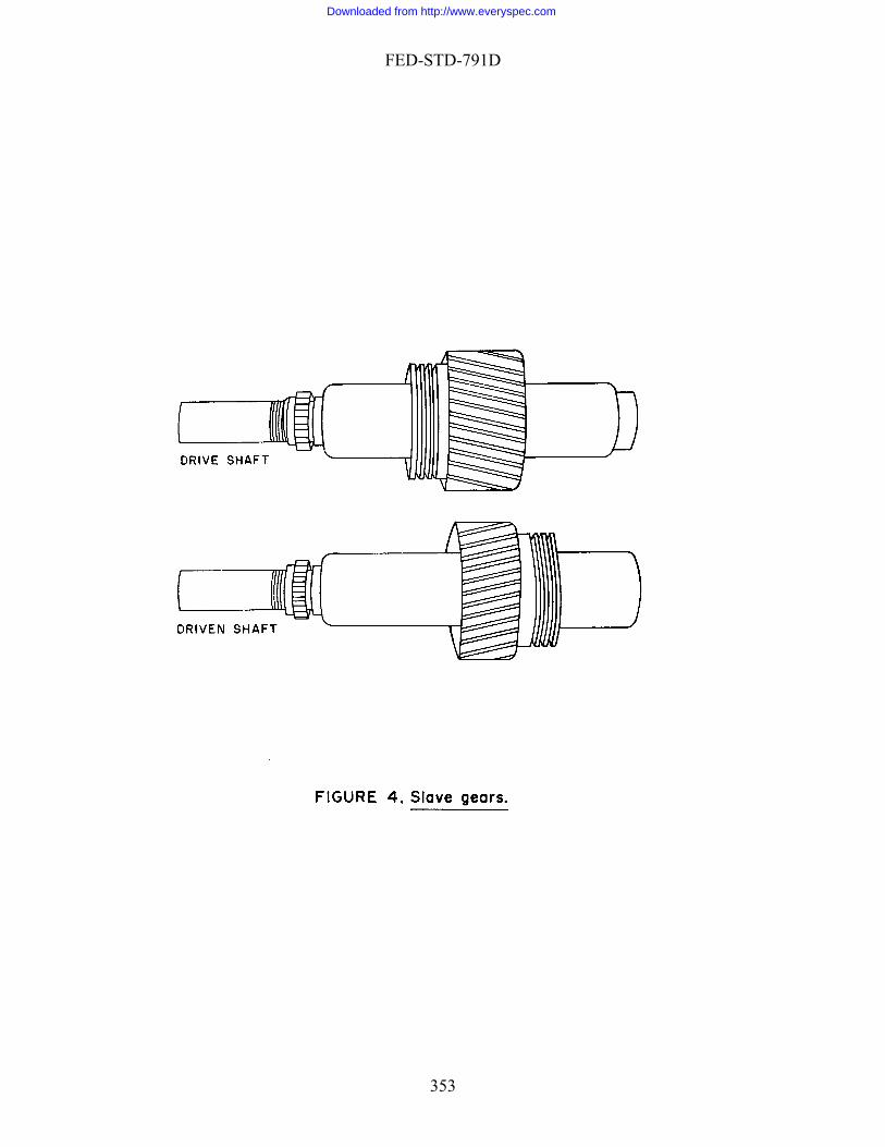
FED-STD-791D
353
Downloaded from http://www.everyspec.com

FED-STD-791D
354
Downloaded from http://www.everyspec.com

FED-STD-791D
355
Downloaded from http://www.everyspec.com
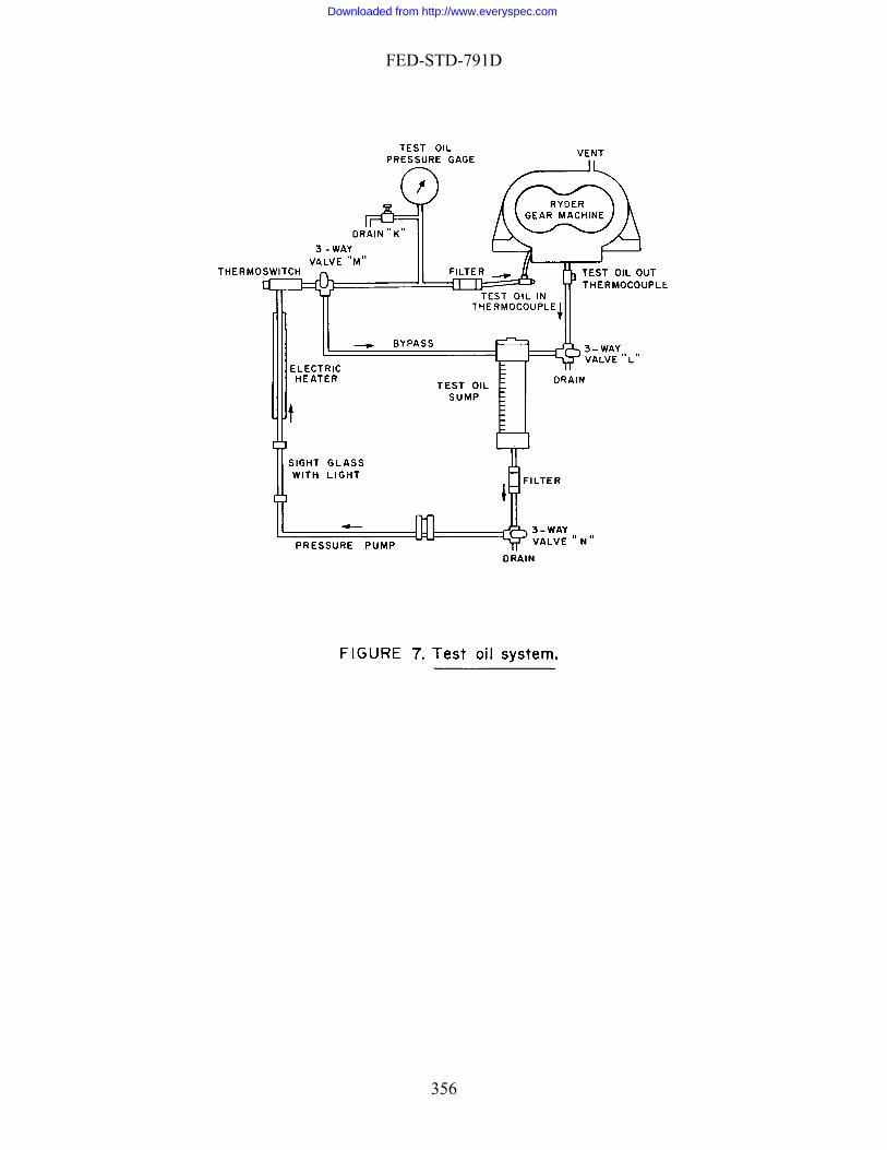
FED-STD-791D
356
Downloaded from http://www.everyspec.com

FED-STD-791D
357
Downloaded from http://www.everyspec.com
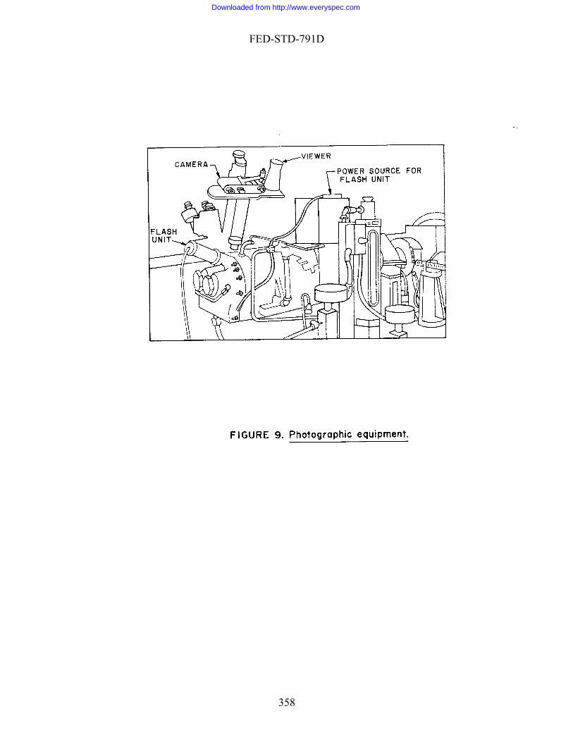
FED-STD-791D
358
Downloaded from http://www.everyspec.com

FED-STD-791D
359
Downloaded from http://www.everyspec.com

FED-STD-791D
360
Downloaded from http://www.everyspec.com

FED-STD-791D
361
Downloaded from http://www.everyspec.com
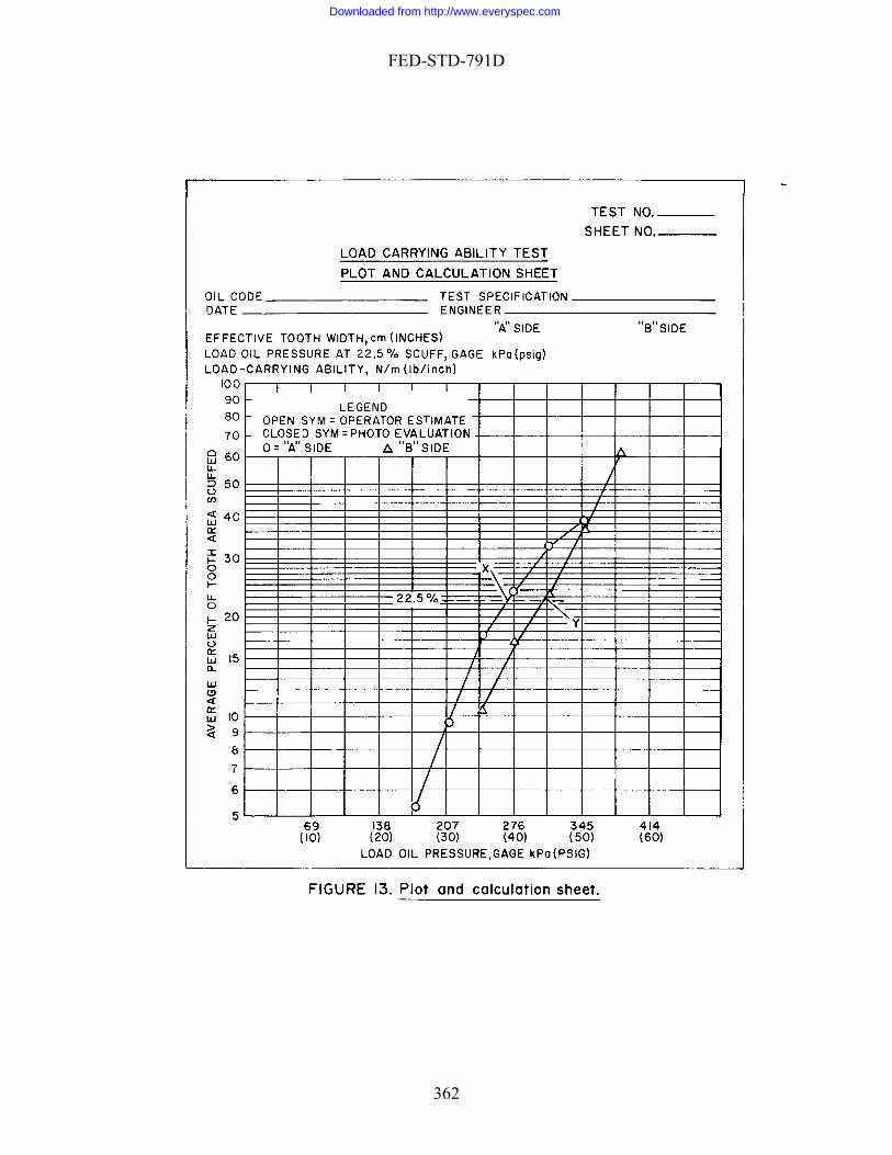
FED-STD-791D
362
Downloaded from http://www.everyspec.com

FED-STD-791D
Method 6517 Sep ber 198
tem 30, 6
HIGH-TEMPERATURE GEAR LOAD-CARRYING CAPACITY OF LUBRICATING
OILS 1. SCOPE
1.1 This method describes a procedure for determining the gear load-carrying capacity of lubricating oils at controlled test gear temperatures of 220°C (428°F) through 371°C (700°F). 2. SUMMARY
2.1 The method consists of subjecting the lubricant to a series of controlled temperature tests at increasing gear-tooth loads using a set of special spur test gears. Each tooth of one of the gears is examined to determine the working area scuffed after each load step. The load-carrying capacity of the lubricant is determined by the load, in pounds per inch of tooth width, required to produce 22.5% average scuff of the total working area of the examined test gear. 3. SAMPLE SIZE
3.1 Approximately 2 L of test oil. 4. REFERENCES, STANDARDS, AND APPARATUS
4.1 Test unit. The apparatus in this method is the WADD gear machine, or equivalent, available from Erdco Engineering Corp., Addison, IL. This apparatus consists of a WADD gear machine adapted to a modified Erdco universal tester drive stand, a support and load-oil system, a test-oil system, a radiometer, and induction heater, and the necessary instruments and controls.
4.1.1 WADD gear machine. The WADD gear machine operates on the same
principle as the Ryder gear machine, the so-called "four-square" principle. However, improvements in material and design permit its operation at test gear temperatures up to 371°C (700°F). Double-row roller bearings are used to support the two parallel shafts, and screw-thread type nonrubbing seals are used to separate the test oil and support oil chambers. As shown on Figure 1, the two parallel shafts (P and Q) are connected by two slave gears (R and S) and two test gears (T and a "Square" tha orequired to operate the machine is only that required to overcome the fr
he slave gears are helical gears and are mad as integral parts of the
U) to form so t the p wer iction losses in the
gears and bearings. T etwo shafts; the test gears are spur gears and are replaceable. Load on the test gears is obtained through the application of a controlled oil pressure in the load chamber (X), which causes an axial movement of one shaft relative to the other. A torsional load is
363
Downloaded from http://www.everyspec.com
FED-STD-791D
th ears. he t ge and lo
btained by arithmetic calculation, calibration, or both. Arithmetic calculation is used erein.
4.1.2 Test gears
us applied upon the shafts due to the helical slave gears, thereby loading the test gThe relation between the tooth load on t tes ars the ad-oil pressure can be oh
. The test gears are special spur gears, made of AMS 6475 steel,
itrided and ground, having 28 teeth, 8.89-cm (3.5-in) pitch diameter, 8 diametral pitch, re angle,0.0000- to 0.00025-cm (0.000- to 0.0001-in) tip relief, and 0.0279-
0.0356-cm (0.011- to 0.014-in) backlash. (Sier-Bath Gear Co., Inc., North Bergen, N.J., 0
NOTE 1:
n22.5° pressuto
7047, part No. SB-19293-AN, narrow gear; SB-19469-AN, wide gear; or equivalent.)
The working area of the gear teeth is finish ground to the required profile
ter nitriding to remove the "white-layer" formed during the nitriding process.
af
NOTE 2: Each set of test gears comprises gears of two different widths. The narrow test gear is used for rating purposes. The mating gear is wider in order to maintain a constant contact width between the two gears at different tooth loads. Both sides of the test gears are used for testing. The "A" side of the gears refers to the side obtained by installing the test gears with the serial numbers facing the end cover. The "B" side is obtained by reversing
ears (serial numbers facing away from the end cover). Test gears can be used only once on each side and then discarded.
4.1.2.1 The entire web of each side of the narrow test gear must be electroplated
rmed, extending from the root iameter of the gear teeth approximately 0.64 cm (1/4 in) toward the center of the gear,
provide
the g
with black chromium. The black chromium rings thus fod
s a continuous black body radiation surface for accurate test gear temperature measurement during test.
4.1.3 Drive system. An Erdco universal drive system, or equivalent, is used to drive the WADD gear machine. A 50-hp induction motor drives the machine through a variable speed dynamatic coupling, a step-up gearbox, and an adapter block to which the WADD gear machine is attached. The only modification required to the drive system is the relocation of the mounting studs in the end of the adapter block to match the holes in the WADD gear machine mounting flange. The test gear speed is controlled by adjusting the field excitation of the dynamatic coupling. By this means accurate speed control can be obtained at the specified test speed of 10,000 rpm.
4.1.4 Support and load-oil system. The support and load-oil system used with the WADD gear machine serves two purposes: To provide lubrication to all necessary parts except the test gears, and to supply load-oil pressure to the load chamber, and thus, the application of load to the test gears. A schematic dia-gram of the support and load-oil system is shown on Figure 2.
364
Downloaded from http://www.everyspec.com

FED-STD-791D
4.1.4.1 The system is charged with approximately 30 L (8 gal) of lubricating oil, type MIL-PRF-7808 or SAE J1966. The support oil temperature measured at the distributing manifold, is maintained at a specified value of 74° 2.8°C (165° 5°F), by means of electrical heaters located in the sump, and a water cooler located after the pump, through the action of thermoswitches. Pressure lines from the distributing manifo
ugh the load chamber located at the rear of the driven shaft. Sufficient oil is provided to maintain a constant "load-oil pressure," and to allow for leakage past the load chpressure quickoil system, shown on Figure 3, affords automatic loading of the machine and a ontinuous recording of the load-oil pressure. In operation, the desired load is set on the
indis recorded. Tvalves which rto return to the
4.1.5
ld lubricate the bearings and helical gears, as well as the adapter housing and the step-up gearbox back to the support oil sump.
4.1.4.2 The action of the load oil circuit for the WADD gear machine is shown
on Figures 2 and 3. Oil from the load adjusting valve, Figure 2, enters the WADD gear machine thro
amber seal. The load bypass valve is opened when it is desired to release the load-oil ly, such as at the end of a test run. The optional automatic recording load
cicator, the load is then automatically changed at a constant rate to the preset value and
he load is automatically released at the end of each test run by solenoid elease the control air pressure to the pneumatic valves allowing the valves ir respective normally closed and normally open positions.
Test-oil system. A test-oil system capable of maintaining a test-oil f 205°C (401°F) is used with the WADD gear machine for re gear load-carrying capacity evaluations. A sch
temperature ohigh-temperatu ematic diagram of the
st-oil system is shown on Figure 4. The capacity of the test-oil system is 1 L. Test oil is supp
ide of the test-oil sump.
telied to the test gears by means of a pressure pump through an inline filter and then
to the jet, located on the unmeshing side of the gears. The oil is gravity drained from the test section through the flow check chamber and returned to the sump. Oil temperature to the test gears is maintained at 205° 2.8°C (401° 5°F) by means of two electrical band heaters located on the outs
4.1.6 Radiometer. A Barnes R-4D1 industrial radiometer, or equivalent, is used
in conjunction with the WADD gear machine to measure the narrow test gear temperature during test. The industrial radiometer consists of two components: (1) the temperature sensing optical head which is located inside the test cell, approximately 137 cm (54 in) from the end cover of the WADD gear machine, and is aimed at the web of the narrow test gear through the hole provided in the gear machine end cover, and (2) the electronics and readout unit which is located in the control console of the test rig.
4.1.7 Induction heater. A Lepel T-5N-3, or equivalent, induction heater having a
5 kW output at 450 kHz with a wide range continuous grid control is used to heat the test gears to the desired test temperature.
4.1.7.1 A load coil transformer is used in conjunction with the induction heater to
minimize power loss from the induction heater. The load coil transformer is mounted
365
Downloaded from http://www.everyspec.com

FED-STD-791D
inside the test cell approximately 38 cm (15 in) to one side of the WADD gear machine. The test gear heating coil, shown in Figure 5 without the end cover, is mounted inside the end cover of the WADD gear machine and is connected directly to the load coil transformer output terminals by removable, silver-plate connectors.
4.1.8 Instrumentation and controls. All except one of the instruments and
controls that require constant attention during test are located on the control console, as shown on Figure 6. The one item requiring constant attention and not included in the control console is the induction heater. The induction heater power supply is normally located abutting the control console for convenience. Attention should be directed to the instruction manual for the specific induction heater used to determine the exact control method to use. Items that do not require frequent attention are located inside the test cell. The functions of most of the instruments and controls are apparent. Therefore, only selected items will be explained further.
4.1.8.1 Speed measurement and control. An electronic counter (Figure 6, item
10), located on the control panel, measures the speed. This instrument is actuated by pulses supplied by a variable reluctance pickup (the variable reluctance being provided by a 60-tooth gear operated from the driven shaft of the step-up gearbox). The rpm adjustment control (Figure 6, item 28), located on the con-sole, regulates the field excitation of the dynamic coupling and thus the gear speed.
4.1.8.2 Control of test-run duration. An electric timer (Figure 6, item 16), located
on the console, is used to control the duration of each test run. As soon as the desired test load and test gear temperature has been reached, the timer is started. After the ten-minute run is over, the timer automatically turns off the drive motor and opens the load-bypass valve. The timer switch must be moved to the "stop" position immediately following coast down of the machine.
4.1.8.3 Support-oil controls. The support-oil pump buttons (Figure 6, item 18) on
the console are connected to the support-oil pressure pump as well as the scavenge pumps. Pressing the start or stop button controls all pumps at the same time. The support-oil heater buttons (Figure 6, item 19) control both the electric heaters and the water cooler through the action of thermoswitches. The support-oil chamber vacuum is measured by a water manometer located on the test stand. A valve connecting the chamber to a vent (Figure 2) should be adjusted to give a chamber vacuum of approximately 2.54 cm (1 in) of water under normal test conditions.
.1.8.4 Control of load-oil pressure4 . The control of load-oil pressure has been
explain
noid circuit will automatically be open by the electric
ed in 4.1.4.2. The load adjusting valve is air actuated and is controlled by the load-adjust control (Figure 6, item 6 or 15) located on the console. The load-bypass valve, is solenoid actuated and is controlled by the load-bypass switch (Figure 6, item 20) on the console. At the end of a run, the sole
timer. This opens the load-bypass valve, but the load-bypass switch on the console remains in the "close" position. For this reason, the switch must be turned to the "open" position prior to the next run.
366
Downloaded from http://www.everyspec.com
FED-STD-791D
4.1.8.5 Emergency stop. The emergency stop button (Figure 6, item 26) on the console stops the driver motor and turns off all the controls except those for instruments. The timer switch and the load-bypass switch remain in the positions to which they were originally set.
4.1.8.6 Scuff rating equipment. A microscope and a light source are used for
visual inspection of the narrow test gear. An optional closed circuit television camera and monitor (Figure 6, item 4) may be used for inspection of the narrow test gear. To inspect the narrow gear, the machine is first stopped. The inspection can then be made through special inspection holes provided in the gear-case end cover. These holes are closed by corks during the test run.
4.1.8.7 Inspection equipment. The standard 18X microscope furnished with the
Erdco Ryder gear machine, or equivalent, is slightly modified by the addition of a supplem bjective-lens opening. The right eyepiece of the microsc
entary lens in the right oope contains a net reticule that divides the gear-tooth area lengthwise into seven
sections. The grid lines provide a convenient means for the visual estimation of the percent of gear-tooth area that has been scuffed.
4.1.8.8 Gear-tooth indexing ratchet. An indexing ratchet is normally used for
rotating the test gears so that the teeth of the narrow test gear can be inspected individually. If the optional closed circuit television camera and monitor are used, a televisi
low-rate check. b Micrometer 0 to 2.5 cm (0 to 1 in) for the measurement of the gross tooth width
romium rings on the web of the narrow test gears:
on antenna rotor may be adapted to engage the output shaft of the step-up gearbox and provide the rotation of the narrow test gear for remote inspection.
4.1.8.9 Additional instruments:
a. Stop watch for oil f
. of the narrow gear.
c. Scale with divisions of 0.04 cm (1/64 in). d. Set of conventional mechanical tools as necessary for assembly, disassembly,
maintenance, and repair.
4.2 Test gear plating procedure. 4.2.1 The following procedure is used to plate the black ch
1. Clean the gear with dry-cleaning solvent and rinse with petroleum ether. 2. Mask the area to be plated with masking tape. (The area to be plated includes
the flat area on both sides of the narrow test gear between the root diameter of the gear teeth and the OD of the test gear hub, not including the fillet.)
3. Place the gear in a wire holder and immerse in hot platers wax. Dip the gear successively until the wax has formed a coating approximately 0.32 cm (1/8 in) thick on all gear surfaces.
367
Downloaded from http://www.everyspec.com

FED-STD-791D
4
y sand blast the exposed portion of the test gear using No. 30 grit aluminum oxide.
7
with distilled water. It is important that all of the liquid nickel solution be removed from the gear and wire holder prior to
12. Clean the gear with dry cleaning solvent and rinse with petroleum ether. 1
. Allow the wax coating to cool and harden. Cut a groove in the wax coating with a knife to expose the masking tape.
5. Remove the masking tape to expose the area to be plated. 6. Lightl
. Immediately following the sand blast, the gear must be rinsed thoroughly with distilled water and placed in the nickel strike for 2 min.
8. Rinse the gear again with distilled water and place in the nickel plate bath. The nickel is plated to a thickness of approximately 0.0025 cm (0.001 in) (approximately 6 min).
9. Rinse the gear thoroughly
proceeding to the chrome plate bath. 10. After thoroughly rinsing the gear in distilled water, place it in the chrome
plate bath and plate until the nickeled area is uniformly covered with black chromium (approximately 20 min).
11. Rinse the gear thoroughly with distilled water. Remove the platers wax from the gear.
3. Dip the cleaned test gear in standard reference oil and store in suitable container until required for test.
NOTE 3: Organic contamination of the nickel solution will produce a wrinkled,
brittle-plated surface which flakes easily. Organic or chloride contamination of the chrome bath will produce a yellowish-brown plate
contamination of either bath exists, discard the solution and prepare new plating solution.
which is unacceptable. If
4.2.2 Test gear nickel strike and plating solution. Approximately 4 L of nickel strike and plating solution is required, as follows:
b. 896 g purified crystalline nickelous chloride (NiC12) and dissolve the crystals.
c hloric acid (HC1) to the solution. d Add additional distilled water to make approximately 3.785 L of solution.
plating solution
a. Prepare the nickel strike and plating solution in a clean borosilicate glass beaker. Add 3 L distilled water to
. Add 308 g reagent grade hydroc
.
4.2.3 Black chromium . Approximately 3.8 L (1 gal) of black lating solution is required, as follows:
b.
d. tate.
p
a. Prepare the chromium plating solution in a clean borosilicate glass beaker. Dissolve 1 kg reagent grade crystalline chromium trioxide (Cr03) in 3.785 L distilled water.
c. Add 1/4 g reagent grade crystalline silver nitrate (AgNO3). Stir solution, cover and place in a dark area for 4 h. Decant and discard precipi
368
Downloaded from http://www.everyspec.com

FED-STD-791D
e. Add 1 g reagent grade barium carbonate (BaCO3). Stir solution, cover and place in dark area for 4 h.
f. Decant and discard precipitate. g. Add 1 g hydrochloric acid. Stir solution, cover and store in dark area until bath
solution is required for plating.
4.2.4 Plating apparatus. The following apparatus is required for plating the test gear:
a.
c. el plate bath.
elee. Plastic covered, 9 gage, copper wire is used to connect the power supply to the
Ring stand or other suitable rack from which the wire gear holder may be suspended.
b. DC power supply (6 to 8 V with variable power output of 0 to 20 A). Nickel bar stock, approximately 5 � 15 � 0.64 cm (2 � 6 � 1/4 in), is used for electrodes in the nickel strike and nick
d. Sheet lead, approximately 15 � 20 � 0.32 cm (6 � 8 � 1/8 in) thick, is used for ctrodes in the black chrome plate bath.
electrodes.
4.2.5 Plating conditions. The following conditions are used for the strike and platin h
y
g bat s:
Solution temperature
Plating time,
min
Power, A
Gear polarit
Nickel strik
Nickel plate
29.4° 2.8°C
13.0
Negative
e
68.3° 2.8°C (155° 5°F)
2
0.5
Positive
Black chrome
68.3° 2.8°C (155° 5°F)
6
20
0.5
Negative
plate (85° 5°F)
5. M
. The ateria
ited in FTMS 791. The synonyms, life hazard, amm , and
spill p
601D).
ATERIALS
5.1 CAUTION - SOME MATERIALS ARE TOXIC AND HAZARDOUSm ls references and standards listed in this section must be handled carefully. Federal Test Method 10000, Material Handling Safety Precautions, is a reference which ists all toxic and hazardous materials cl
fl ability, handling and storage precautions, emergency treatment and measuresractices of each chemical are explained.
5.2 Lubricating oil, MIL-PRF-7808 or SAE J1966.
95.3 Dry cleaning solvent (A-A-5
369
Downloaded from http://www.everyspec.com
FED-STD-791D
5.4 Petroleum ether (60° - 90°C)[1,4,0].
5
5
5 O3)[u,u,u].
5.12 Hydrochloric acid [3,0,0].
5.14 Sheet lead [u,u,u]. 5. 5 Standa r il to m S ropu s
AFWAL/POSL, Wrigh FB, O 3 [u,u,
6 .
ating
ugh test, the te ar temperature ntrolled at 2.8°C ( 5°F), or the value required by the applicable lubricant specification. Table 1 presents a list of add ting conditions which are also controlled within the
mits specified. With the tester operating within the specified limits, the test gears are kPa gage (5 psig) load oil pressure (nominal 230 lb/in tooth load), and
en at successive increments of 34.5 kPa gage (5 psi). The duration of each loading period
5.5 Platers wax [u,u,u]. .6 No. 30 grit aluminum oxide.
5.7 Purified crystalline nickelous chloride (NiC12)[u,u,u].
5.8 Reagent grade hydrochloric acid (HC1)[3,0,0].
5.9 Reagent grade crystalline chromium trioxide (Cr03)[u,u,u]. .10 Reagent grade crystalline silver nitrate (AgNO3)[u,u,u].
.11 Reagent grade barium carbonate (BaC
5.13 Nickel bar stock [u,u,u].
1 rd eference ot-Patterson A
be obtained froH 45433-656
U AF Aero Pu].
l ion Lab,
. PROCEDURE
6.1 Oper
Conditions
6.1.1 Thro428°
out the entire st ge is co 220°
itional operaliloaded first to 34.5th
is 10 min 5 s. At the end of each ten-minute loading period, the tester is stopped and each tooth of the narrow test gear is examined to determine the percent of tooth area scuffed.
370
Downloaded from http://www.everyspec.com
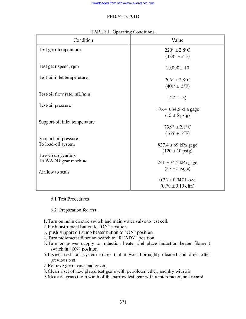
FED-STD-791D
TABLE I. Operating Conditions.
Value Condition Test gear temperature Test g Test-o Test-o flow rate, mL/min Test-o pressure Suppo Support-oil pressure To loa To ste
220° ± 2.8°C (428° ± 5°F)
10,000± 10
205° ± 2.8°C
± 5°F)
71± 5)
03.4 ± 34.5 kPa gage (15 ± 5 psig)
73.9° ± 2.8°C (165°± 5°F)
827.4 ± 69 kPa gage
± 34.5 kPa gage (35 ± 5 gage)
0.33 ± 0.047 L/sec (0.70 ± 0.10 cfm)
ear speed, rpm
il inlet temperature
(401°
il(2
il1
rt-oil inlet temperature
d-oil system
p up gearbox To WADD gear machine
(120 ± 10 psig)
241
Airflow to seals
to induction heater and place induction heater filament switch in “ON” position.
6. Inspect test –oil system to see that it was thoroughly cleaned and dried after previous test.
7. Remove gear –case end cover. 8. Clean a set of new plated test gears with petroleum ether, and dry with air. 9. Measure gross tooth width of the narrow test gear with a micrometer, and record
6.1 Test Procedures 6.2 Preparation for test.
1. Turn on main electric switch and main water valve to test cell. 2. Push instrument button to “ON” position. 3. push support oil sump heater button to “ON” position. 4. Turn radiometer function switch to “READY” position. 5. Turn on power supply
371
Downloaded from http://www.everyspec.com

FED-STD-791D
10. Install test gears on ng out ward ( narrow gear on dri de gear on driven shaft ), matching tim rks on shafts and gears. Check for proper setting of the retaining nuts and lock washers. After
taining nuts, bend one tang of each lock washer to lock the retaining nuts in position.
11. Loosen the lock nut on the driven –shaft adjusting pin (at rear of gear case ) , and ng pin until driven shaft is free to move to rearward
position without touching the adjusting pin. Using a scale set adjusting pin so that move through only one –half of the n el ( from
extreme rearward position to extreme forward position k nut on adjusting pin.
nd cover with induction heating coil 13. Connect induction heating coil in end cover to load coil r. Visually
on of induction heating coil relative to the test gear hubs. NOTE 4. The induction heating coil should not touch either test gear and should be insulated from the test end cover. An ohm meter may be used t e coil is insulated from the end cover and test gears.
ater supply to induction heater load coil ction heating coil.
entilating blower in load coil transformer. ing blower connected to gear-case
17. Turn on air to non rubbing seals. Adjust to appr ge (1
NOTE 5:
proper shafts with the serial number facive shaft, wi ing ma
tightening the re
unscrew adjusti the extreme
the driven shaft can ormal free trav). Tighten loc
12. Re install gear-case etransforme
check positi
o insure that th
14. Turn on w transformer and indu
15. Turn on v16. Turn on ventilat end cover.
oxim l gaate y 6.9 kPapsig).
Approximately 0.33 L/sec (0.7 cfm) of air (total for both air seals) is required for the nonrubbing air seals to function
1 with approximately 1 L of test oil. 19. Start test-oil pump motor, and immediately open test-oil drain line from
and pressuretrol to allow new test oil to fill the line to the gage and pressuretrol. Close test-oil drain line.
se after turning support oil sump heaters
2 l to "ZERO" position.
5°F), adjust the support oil supply pressure to the required values. rpm counter by setting the input-sensitivity control
"ONE e
input-sensitivity control to about midscale.
correctly.
8. Fill test-oil sump
test-oil pressure gage
20. Push test-oil heater button to "ON" position. 21. Allow approximately 20 min to elap
on (step 3). Then start support oil pumps. 22. Turn timer switch to "STOP" position. 23. Check electric timer to insure it is set to 10 min and 0 s, then lock timer dial. 4. Turn rpm-adjust contro
25. When the support-oil temperature is up to the specified value of 73.9° 2.8° C (165°
26. Check calibration of the to the "CHECK" position and the gate-selector switch to theSECOND" position. The counter should read "60." After checking, turn th
372
Downloaded from http://www.everyspec.com

FED-STD-791D
27. When the test-oil temperature is up to the specified value of 205° 2.8°C (401° 5°F), check the test-oil flow rate as follows: Adjust the speed of the test-oil pump motor until the test-oil flow is approximately 270 mL/min. Turn flow-check valve (Figure 4) to the closed position, and measure the time required to fill the flow-check chamber to the tip of the wire indicator. The time required should be 30 s. Turn flow-check valve to the open position to allow the test oil to drain to the test-oil sump. If the time required to fill the flow-check chamber to the tip of the wire indicator varies from the 30-second requirement by more than 1 s, readjust the test-oil pump motor speed and recheck test-oil flow rate as above.
NOTE 6: The test-oil in pressure is maintained at 103.4 34.5 kPa gage (15 5
psig). If the test-oil pressure is outside the specified range, a different size test-oil jet must be used. The test-oil jet sizes normally used are 0.066 and 0.081 cm (0.26 and 0.032 in) diameter, depending upon the test oil
tector spot position on narrow test gear.
NOTE 7:
viscosity.
28. Turn radiometer function switch to "NORMAL RANGE" position. 29. Check radiometer temperature de
Refocus temperature detector if necessary.
The radiometer temperature detector must be focused accurately on theblack chromium ring of the narrow test gear to
rrect test gear
6.2. sequence on "A" side of test gears
insure cotemperature indication.
1 Test .
NOTE 8: The "A" side of the gear refers to the side obtained by installing the test gears with the serial numbers facing the gear-case end cover. The "B"
that the serial numbers
1.
NOTE 9:
side is obtained by reversing the test gears suchface the gear case.
Turn radiometer function switch to "READY" position. Recheck test-oil flow rate as in step 27 of 6.2.1. 2.
3. Determine radiometer reference temperature using null meter on radiometer
The reference temperature must be subtracted from the predetermined test
tained during the test run.
4.
6. 7.
gear operating temperature. After determining this difference, use thisvalue to determine from a temperature/radiometer reading calibration chartthe radiometer reading which must be main
Set radiometer scale selector to appropriate scale for test temperature desired. 5. Turn radiometer function switch to "NORMAL RANGE" position.
Turn on air supply to automatic load-control unit. Check to see that the rotating device of the gear-tooth inspection equipment is in the disengaged position.
373
Downloaded from http://www.everyspec.com
FED-STD-791D
8. Check automatic load-control set point to see that load set point is on "O." Start drive motor. Increase gear speed by turning rpm-adjust control clockwise until the specified 10,000 100 rpm is obtained. Turn on power to induction heater plate and slowly adjust plate control until the radiometer reading determined in step 3 is obtained. Set automatic load-control set point to 34.5-kPa gage (5-psi) load-oil pressure. Check gear speed, and adjust if necessary. Check gear temperature, and adjust
9. 10.
11.
12.
13. 14. plate control if necessary. 15. Turn timer switch to "START" position. The ten-minute run now begins.
val17. Re18. At
off to the drive mwill rem e rpm-adjust will remain in the
y set load
19. 20. ws:
ilb. Rec. Install microscope or television camera and inspection light.
the contact area of the tooth.
g. Op
Repeat for No. 3 tooth, etc, until h. Rem ent and replace corks in holes.
a23. Co
the ture, visually estim
ore is
16. Maintain the test gear temperature and speed at the predetermined specified ues. cord all pertinent data about midway of the test run. the end of the ten-minute run, the timer will automatically turn the power
otor and reduce the load to zero. However, the timer switch ain in the "START" position, th
running position, and the load set point will remain at the previouslposition. Restore these to their respective "OFF" positions. Turn induction heater plate power off. Make visual scuff inspection of each tooth of the narrow test gear as follo
a. Turn 3-way valve (Figure 4) to bypass the gear machine and return the test o to the sump.
move corks from inspection holes in the gear-case end cover.
d. Focus microscope and adjust grid lines overe. Set indexing-rachet wheel to "No. 1" position. f. Estimate the percent scuff of No. 1 tooth as accurately as possible but at least
to the nearest 5%, and record the value (see Figure 7). erate the test gear rotating device to give No. 2 tooth, and repeat (f).
all 28 teeth have been examined. ove inspection equipm
i. Lock test gear rotating device in disengaged position. j. Turn 3-way valve to running position.
21. Repeat step 3 of 6.2.2. 22. Repeat steps 7 through 20 at the next test load of 69 kPa gage (10 psig)
lo d-oil pressure. ntinue the test at 34.5-kPa gage (5-psi) load-oil pressure increments until average scuffed area for all 28 teeth is close to 22.5%. At this junc
ate the percent effective tooth width to the nearest 1%, and record the value.
pressure24. Further continue the test at 34.5-kPa gage (5-psi) load-oil 30% or mincrements, until an approximate average scuffed area of
obtained. 25. Push test-oil heater button to "OFF" position.
374
Downloaded from http://www.everyspec.com

FED-STD-791D
26. Push support-oil heater button to "OFF" position. 27. Push support-oil pressure button to "OFF" position.
29. "OFF" position.
32. est-oil sump, take 50-mL test-oil sample, and measure the amount f test-oil measured plus the 50-mL
35. gear-case end cover. rd the gear case again
37. 38. nd blow off with
40. jet with compressed air. 4 l to load coil
44 either. Blow out line screen
44. petroleum ether and
45.
28. Turn radiometer function switch to "READY" position. Switch induction heater power supply to
30. Turn off water supply to induction heater load coil transformer and induction heating coil.
31. Turn off ventilating blower connected to gear-case end cover. Remove tof test-oil remaining. Record the amount osample.
33. Disconnect induction heating coil from load coil transformer. 34. Disconnect ventilating blower from gear-case end cover.
Remove36. Reverse test gears so that the serial numbers face towa
matching the timing marks on the shafts and test gears. Check for proper seating of the retaining nuts and lockwashers. After tightening the retaining nuts, bend one tang of each lockwasher to lock the retaining nuts in position. Adjust driven shaft in accordance with 6.2.1, step 11. Rinse face of gear case and test gears with petroleum ether acompressed air.
39. Rinse inside of gear-case end cover, including the test-oil jet, with petroleumether and blow off with compressed air. Blow out test-oil
1. Reinstall gear-case end cover and connect induction heating coitransformer.
2. Reinstall ventilating blower to gear-case end cover. 3. Clean test-oil line screen filter with petroleum
filter with compressed air. Rinse test-oil sump, lines, pump, and inlet filter withblow off with compressed air. Reassemble test-oil system.
6.2.2 Test sequence on "B" side of test gears. 1. Turn on water supply to induction heater load coil transformer and induction
3. de of the test gears by following the procedure outlined in
4. 5. 6. d cover and test-oil jet with petroleum ether.
8. 9. ction heater filament switch in "OFF" position.
heating coil. 2. Turn on ventilating blower connected to gear-case end cover.
Proceed on "B" si6.2.1, steps 18 through 29, and 6.2.2, steps 1 through 35. Remove used test gears. Rinse gear-case face and shaft ends with petroleum ether. Rinse gear-case en
7. Reinstall gear-case end cover (without test gears). Turn radiometer function switch to "OFF" position. Place indu
10. Turn off power supply to induction heater.
375
Downloaded from http://www.everyspec.com

FED-STD-791D
11. Turn rpm counter to "OFF" position. 12. Push instruments button "OFF". 13. Turn off main electric switch to test cell. 14. Turn off main water valve to test cell.
6.2. stop3 Emergency .
2. 3. induction heater power supply.
1. Push emergency stop button. Push instruments button "OFF." Turn off
4. Turn off main water valve to test cell.
6.3 Inspection and rating.
1 6.3. Scuffed area. The scuffed area of a gear tooth is that area from which the ng marks have been removed by scratching, scoring, abrasion, and wear. As igure 7, area A and B are scuffed; area C is not scuffed. Note that only the
axial grindishown on F actua k ce is considered in the defini o
l wor ing portion (areas A plus B plus C) of the tooth surfation f areas.
6.3.2 Percent of tooth area scuffed. The percent of tooth area scuffed is that he working surface of a gear tooth that haportion of t s been scuffed.
Refer o
he p n estimated visually to the nearest 5% for each dividu the eyepiece of the inspection
micro c
ring t Figure 7,
100 * C B A
B A = 100 * area scuffed = scuffedarea tooth Percentage ± area working ±±
Tin
erce t of tooth area scuffed is al tooth, with the aid of a net reticule mounted in ope, or a grid placed over the monitor tube. s
6.3.3 Average percent of tooth area scuffed. The average percent of tooth area e algebraic avscuffed is th
test g
.
erage of the percent of scuffed area of all 28 teeth of the narrow ear. Calculate this value to the nearest 1%.
4 Effective tooth width6.3 . The effective tooth width is the actual width of the
narrow-gea ar. For test gears curren s 98% of the gross
r tooth that is in contact with the tooth of the wide getly available, the percentage effective tooth width may be taken a
tooth width by means of a micrometer. See 7.1 for calculation. 6.3.5 Load-carrying capacity. The load-carrying capacity of
cent of tooth are a lubricant is
define t a scuffed is 22.5% for th r tlined herein.
d as he gear-tooth load at which the average pere nar ow test gear as determined by the method ou
376
Downloaded from http://www.everyspec.com
FED-STD-791D
6.3.5.1 Determination of load-carrying capacity. Using semi-log paper (Figure 10), plot th scuffed for the narrow test gear versus the load-o e the load-oil pressure at which the avera r lculate load-carrying capacity, see 7.2.
cedure
e average percent of tooth area il pr ssure. Determine from the plotted curve
ge pe cent of tooth area scuffed is 22.5%. Ca
6.4 Relative rating pro . This procedure consists of reporting the load- arrying capacity of an oil under test as a percentage of the load-carrying capacity of a
standard ref same test apparatus. Details of this relative rating procedure are given in the following paragraphs:
e rating
cerence oil obtained using the
6.4.1 Determination of reference oil averag .
NOTE 10: All load-carrying capacity tests on the standard reference oil are conducted
rence oil. If the high and low values obtained do not differ by more an 140 N/m (800 lb/in), the average is taken as the reference oil rating. If the high low
values aken as the reference
il rating.
6.4.1.2 After a major overhaul to a rig such as a bearing or shaft replacement, four determinations (two gears) shall be conducted on the standard reference oil. If the average of these ratings does not differ from the average obtained prior to the overhaul by more than 52.56 N/m (300 lb/in), and the high and low valves obtained do not differ by more than 140 N/m (800 lb/in), this average will be taken as the reference oil rating. If
e ratings obtained do not meet the above criteria, four additional determinations (two
eferen
ining the previous reference oil rating a
NOT
with Test #6517, using AMS 6260 steel test gears at 165°F test temperature conditions.
6.4.1.1 For a new rig, at least eight determinations (four gears) shall be conducted
on the standard refeth
differ by more than 140 N/m (800 lb/in), four additional determinations (two gears) shall be conducted and the aver-age of the 12 determinations to
thgears) shall be conducted and the average of all eight determinations taken as the reference oil rating.
6.4.1.3 At least two determinations (one gear) shall be conducted on the standard
r ce oil for each 20 determinations made on oils under test. The reference oil rating is a progressive rating in that it consists of the average value obtained on the last eight determinations, i.e., when two new determinations are conducted, the two oldest determ ns of the eight determinations used in determinatio
re dropped, the two new ratings replace them and a new reference oil rating are dropped, the two new ratings replace them and a new reference oil average rating is obtained. The sole exception to the above is where it is necessary to run 12 determinations to establish an average on a new rig. (See 6.4.1.1)
E 11: Maximum and minimum acceptable average ratings for the reference oil are 578.1 N/m (3300 lb/in) and 438 N/m (2500 lb/in), respectively. Rigs which do not give an average reference oil rating within these limits shall
377
Downloaded from http://www.everyspec.com

FED-STD-791D
not be considered as being satisfactory. Faulty maintenance practices, improper test procedures, or the need for major overhaul can be indicated if the average on the reference oil does not fall within these limits.
6.5 Data Sheets
7. CALCULATIONS
.1 Calculate the effective tooth width using following equation:
here:
6.5.1 The suggested data sheets are shown on Figures 8 and 9. These sheets have
areas provided to enter all pertinent information obtained during test and inspection.
7
W 0.98 = W 12
w
W2 = effective tooth width in cm (in). W1 = measured gross tooth width in cm (in).
7.2 Calculate the load carrying capacity from the following equation:
W = P
2 KL
) of tooth-face width
where: P = load-carrying capacity of the lubricant in N/cm (lb/in) of tooth-face width. K = WADD gear machine constant (11.5 by definition). L = load-oil pressure Pa gage (psig). W2 = effective tooth-face width in cm (in).
8. REPORTING
8.1 Report the following items:
a. The individual ratings of the test oil obtained from the "A" and "B" sides of all gears tested in N/cm (lb/in) of the tooth-face width (6.3.5.1).
b. The average rating of the test oil in N/cm (lb/in) of tooth-face width. c. The standard reference oil average rating in N/cm (lb/in
(6.4.1).
378
Downloaded from http://www.everyspec.com

FED-STD-791D
100* rating average oil reference
rating average oil Test = (percent) oil test the of rating relative The d.
9. PRE
Method prepared by:
L/POSL - 1986
CISION
9.1 Precision data have not been developed for this method.
Air Force - AFWA
379
Downloaded from http://www.everyspec.com

FED-STD-791D
380
Downloaded from http://www.everyspec.com

FED-STD-791D
381
Downloaded from http://www.everyspec.com

FED-STD-791D
382
Downloaded from http://www.everyspec.com
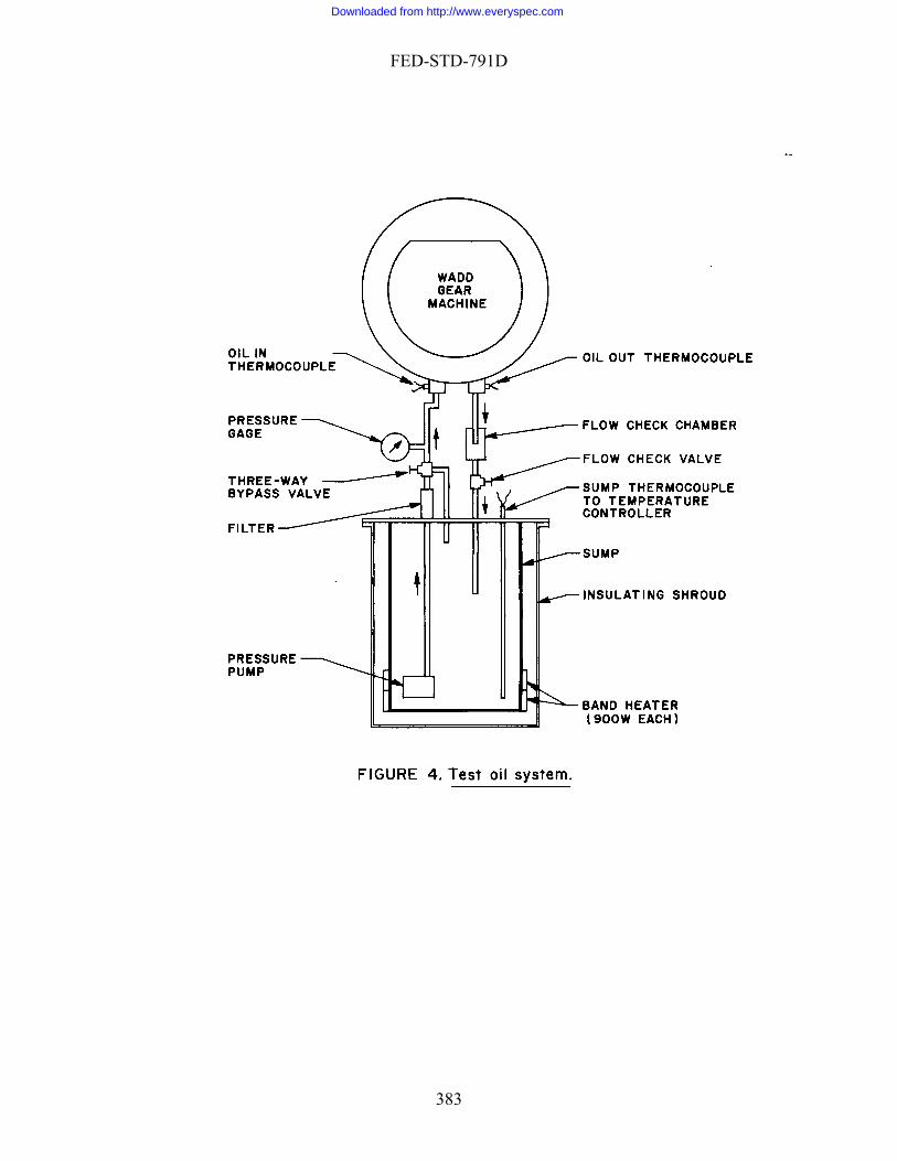
FED-STD-791D
383
Downloaded from http://www.everyspec.com

FED-STD-791D
384
Downloaded from http://www.everyspec.com

FED-STD-791D
385
Downloaded from http://www.everyspec.com
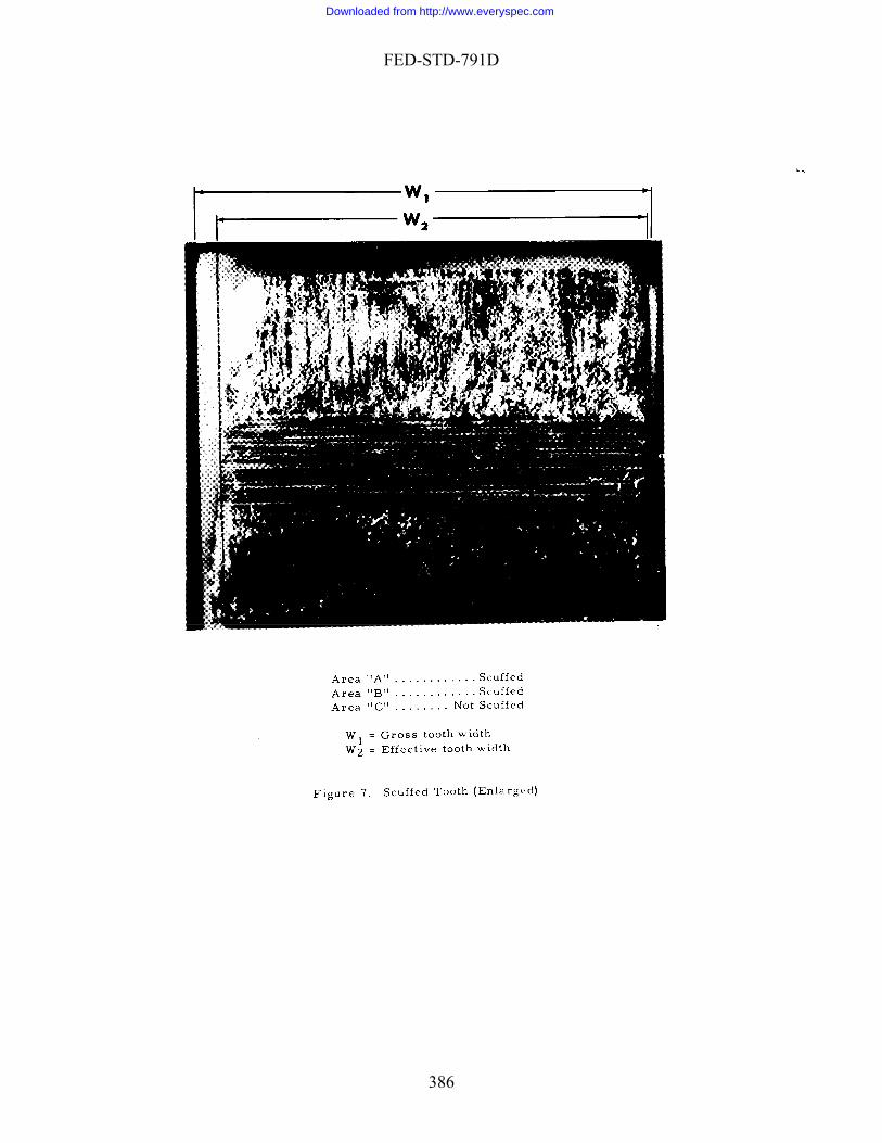
FED-STD-791D
386
Downloaded from http://www.everyspec.com
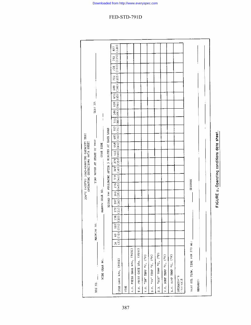
FED-STD-791D
387
Downloaded from http://www.everyspec.com
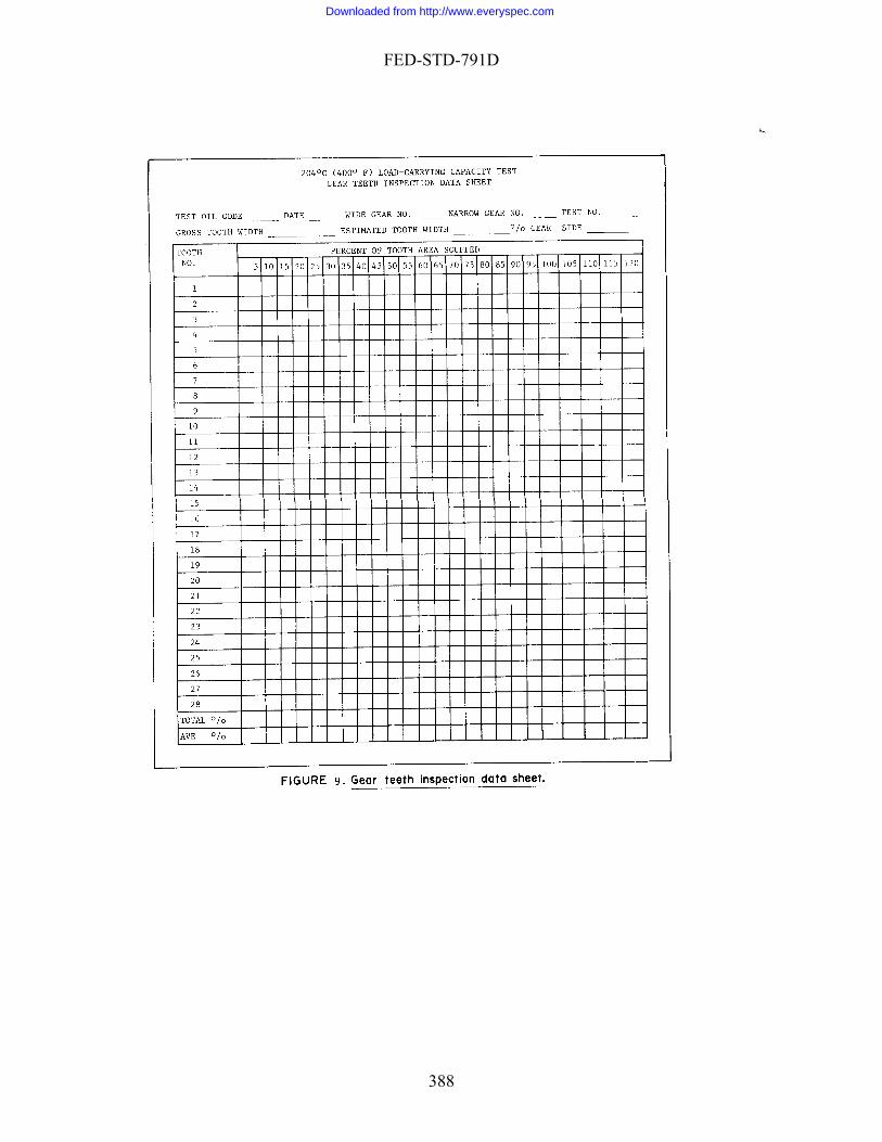
FED-STD-791D
388
Downloaded from http://www.everyspec.com
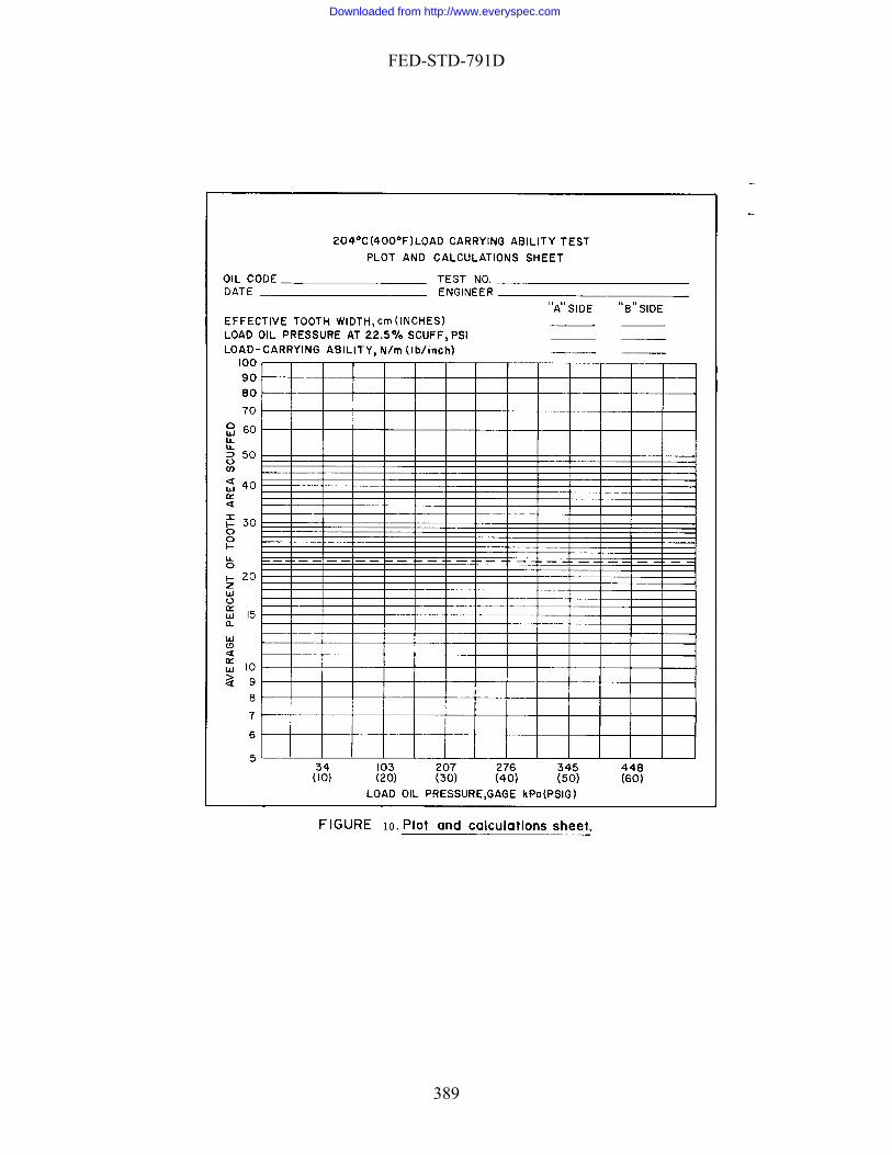
FED-STD-791D
389
Downloaded from http://www.everyspec.com
FED-STD-791D
Method 7501 August 7 , 2006
LOW TEMPERATURE TORQUE TEST METHOD FOR LUBRICATING GREASES 1. SCOPE
1.1 This test method determines the torque values of lubricating greases using tapered roller bearings when subjected to low temperatures. The method was developed using greases giving torques of less than 80 N.m at -54 °C. 2. APPLICABLE DOCUMENTS
2.1 Government documents. 2.1.1 Specifications. The following specification forms a part of this document
to the extent specified herein. Unless otherwise specified, the issues of these documents shall be those listed in the issue of the Department of Defense Index of Specifications and Standards (DODISS) and supplement thereto, cited in the solicitation (see 6.2).
SPECIFICATIONS MILITARY MIL-G-23827 - Grease, Aircraft and Instrument, Gear and Actuator Screw.
(Unless otherwise indicated, copies of federal and military specifications, standards, and handbooks are available from the Naval Publications and Forms Center, (ATTN: NPODS), 5801 Tabor Avenue, Philadelphia, PA 19120-5099, or at http://assist.daps.dla.mil/quicksearch/). 3. SUMMARY
3.1 A worked sample of the test grease is packed into four test specimen assemblies which simulate the automotive front wheel bearing system. These assemblies are mildly heated and then rotated one revolution. The test assemblies are soaked for 16 hours at -54 a
°C. At the end of this time, the two test assemblies are rotated consecutively t 1 rpm and both breakaway (starting torque) and torque after 5 minutes of rotation unning torque) are then determined. The two remaining test assemblies are tested after
the additional four hours cooling to restore the test temperature. 4. SIGNIFICANCE
4.1 This method was developed to assess the low temperature performance of greases at -54 °C and clearly distinguish between differing grease formulations. The
(r
390
Downloaded from http://www.everyspec.com
FED-STD-791D
torque d ith the low temperature performance ata obtained from this test method agree wf military greases in the field. A correlation was found between th ue nd the apparent viscosity range of 5,000 - 30,000 poises at a shear rate of 25 reciprocal conds.
. DEFINITIONS
5.1 Breakaway torque
o e breakaway torqase
5
. The maximum torque measured at start of rotation. 5.2 Running torque. The torque value after rotation for a specified period of
time (5 minutes). 6. APPARATUS
6.1 Low temperature torque test unit. This test unit consists of an ASTM D 4693 test apparatus which is designed with a cold chamber and two spindle drive system
6.1.1 The low temperature test chamber consists of a cascade mechanical ower, and a solid state electronic temperature controller. This
hamber is designed to maintain the test temperature down to -58 °C. The chamber tored with a T type thermocouple.
lt
nd pulley, a gear reducer and a solid stainless steel extension shaft (diameter: 2.2 cm, length: d
tension
ported by two sealed roller bearings which are bricated with MIL-G-23827 grease. Only the outside supporting bearings are rotated
n drive shafts during the test time.
acity:
ad
nd applies 10 volts for e input bridge excitation.
6.1.4 The test specimen assembly is as specified in the ASTM D 4693 test method.
s, torque measuring system, test specimen assembly, and data acquisition and control system. The schematic diagram of US Army low temperature torque test unit is shown in figure 1.
refrigeration system, a blctemperature is moni
6.1.2 The spindle drive system consists of a 1/3 hp electric motor, a timing bea
25.6 cm). The gear reducer provides 84 N.m of maximum output torque anapproximately 1 rpm of fixed speed. Two spindle drive systems are mounted externallyand connected to the inside of the cold chamber using a solid coupling and exshaft, respectively. These shafts are supluwith the extensio
6.1.3 The torque measuring system consists of a strain-gage load cell (cap136 kg), a cylindrical rod (diameter: 1.9 cm length: 22.5 cm), a load button and a DC power supply (capacity 20 V). Two torque measuring systems are mounted on a plate which is situated below and external to the cold chamber. To measure the grease torque, rods are connected to the inside of the cold chamber with the load cell. A spherical lobutton is attached to the top of the rod to allow for the adjustment of the level of the torque arm. A DC power supply is connected to both load cells ath
391
Downloaded from http://www.everyspec.com
FED-STD-791D
6.1.5 The data acquisition and control system consists of a HP data acquisition and control unit, a HP computer as system controller and the user operation program (LOWTEMP). The HP data acquisition and control unit also contains three plug-in assemblies: relay multiplexer assembly for measuring the torque value, relay multiplexer ssembly with thermocouple compensation, and high voltage actuator to control the drive
6.4 Spindle holder or test preparation stand.
6.5 Ultrasonic cleaner.
asystem.
6.2 Laboratory oven, gravity convection, 70 ±3 °C. 6.3 Grease packer, as described in the ASTM D 3527 test method.
7. CALIBRATION
7.1 Torque calibration. Attach a support disk (diameter: 4 cm), for holding the dead weight, on the top of the rod. Measure output (millivolt) of load cell as a known force (dead weight: 0.5 kg, 1-10 kg) is applied to load cell at the room temperature. Then, t
. ly at
icate that it is required.
. Prior to use in this test, new bearings shall be conditioned by installing any suitable wheel bearing grease in the bearing
.1 Clean the test bearings with heptane or equivalent reagent using a ultrasonic cleaner
he calibration equation shall be determined using the statistic method. The Method of Regression analysis is very suitable to develop the torque calibration equationThe typical calibration curve is shown in figure 2. This calibration needs be done onthe time of initial setup and when occasional checks ind
7.2 Temperature calibration, as described in ASTM D 4693, or equivalent. 7.3 Spring calibration, as described in ASTM D 4693, or equivalent.
8. TEST BEARINGS.
8.1 Use LM67010-LM67048 and LM11910-LM11949 inboard and outboard
bearings, respectively. Timken bearings are suitable
s and running them at room temperature for 48 hours at 1,000 rpm under a normal thrust load of 111 N. ASTM D 3527 test apparatus is suitable for conditioning the bearings. Note 1. The bearings must be keyed to prevent race rotation on spindle. 9. PROCEDURE
9 and dry with compressed air.
392
Downloaded from http://www.everyspec.com
FED-STD-791D
9.2 Work a grease sample for 60 double strokes using the full scale grease or one-half scale grease worker at room temperature.
9.3 Weigh an inboard and outboard bearing cone to the nearest 0.1g. 9.4 Pack a worked grease sample into the test bearings (inboard: 3.0 ±0.1 g.
outboard: 2.0 ±0.1 g) using the following bearing packing procedure: Fill the bearings with th STM D 3527 test method. Use care to prevent relative rotation of rollers and bearing components while removing the con off excess grease flush using a small spatula. Wipe all grease from cone bore, cone back face, exterio a clean lint free cloth or towel and reweigh. Adjust the grease weight in the inboard and outboard cones to 3.0 and 2.0 ±0.1g, e to the groove between the cage and cone back face.
bearing cups installed in the hub using heptane and apply a thin of the test grease to the races.
.
lied to e test bearings with a calibrated spring-loading device.
.7 Prepare four test specimen assemblies using the above test assembly prepara
rbing the test assemblies, place them in an oven preheated to 70
±3 C for 1 hour.
atus
o hout any handling of the test assemblies, the torque arms should be placed
ertically with the drive motors.
9.11 Place the other two test assemblies inside the cold chamber in preparation next tests.
9.13 Start 16 hour cold-soak at -54 ±0.5 °C.
e worked test grease using a grease packer utilized in A
es from cups and in all subsequent wiping and handling steps. Strike
r cage surfaces and exposed roller surfaces with
by wiping or adding greas 9.5 Clean the
film 9.6 Set-up a test specimen assembly according to the following procedure:
Without any rotation of the test bearing, the inboard bearing is installed on the spindleThen, this spindle is mounted on the test preparation stand which was designed for holding it in a vertical position. The hub is gently set on the inboard bearing with the torque arm aligned with the spindle set screw. (i.e., pointing in the same direction). Then, the outboard bearing is placed on the hub. The thrust force (400 N) is appth
9tion procedure.
9.8 Without distu °
9.9 Rotate the test specimen assemblies for 1 revolution using the test appar
at room temperature. 9.10 Install two test specimen assemblies on each drive shaft for the first tw
tests. Witv
(cold soak) for the
9.12 Insert two thermocouples (T type) in the test spindles to monitor the test temperature.
393
Downloaded from http://www.everyspec.com
FED-STD-791D
9.14 Following a 16 hour cold-soak, the two torque tests shall be consecutivelperformed using the LOWTEMP computer applicat
y ion program. The following
additional test conditions are applied to the torque test runs:
Test tem Test t
.
to
0.2 Running torque (N.m) at 5 minutes.
tions shall be calculated by the average of two test runs. 11. PR
atability
ue at 5 minutes: 7%
Note 3. ffer
not been established.
y
perature: -54 ±0.5 °C ime: 5 minutes
Spindle speed: 1 rpm Data scanning interval: 20 centiseconds The torque reading starts when torque value is >0.1 N.m
9.15 Store the test results on a floppy disk and plot them on the formatted papers 9.16 Cut off the cooling system, and remove the tested specimen assemblies from
the drive shafts and place them in the preheated oven until completely dried in order preclude rust formation.
9.17 For the second series of tests, the two remaining test specimen assemblies
shall be set up on the drive shafts identically to the previous tests. 9.18 Resume the cooling for the next four hours to restore the test temperature. 9.19 After four hours, two additional torque data shall be generated using the
above torque measurement procedure. 10. REPORT
10.1 Breakaway torque (N.m). 1
Note 2. Both determina
ECISION
11.1 Repe Breakaway torque: 10%
Running torq
Duplicate results by the same operator should be considered suspect if they difrom the mean by more than the above amounts at the 95 percent confidence level.
11.2 Reproducibility has
Method prepared b
Army – AT - 2006
394
Downloaded from http://www.everyspec.com

FED-STD-791D
Test Method 7502 August 7, 2006
ING POWER BY A SOIL TEST METHOD
ndix is a mandatory part of the pecific
dards:
ils (Metal squares)
. SUM
steel coupon is immersed in the test lvent and then placed in an ultrasonic cleaner maintained at up to 50 C. The grease is
f sonic ined based on the time to completely remove grease
4. SIGNIFICANCE AND USE
4.1 This test m ency of all types of cleaners and
5. APP
5.1 Ultrasonic Cleaner
5.2 Beaker, 200ml
5.3 Test specimen assembly
SOLVENT CLEAN
1. SCOPE
1.1 This test method is used for determining the cleaning power of solvents that have been subjected to soiled mechanical parts. This Appes ation. The information contained herein is intended for guidance only.
2. REFERENCED DOCUMENTS
2.1 Military Stan
MIL-PRF-10924, Grease, Automotive, Artillery (GAA) 2.2 Federal Standards:
Federal Test Method Standard 791C, Method 5308.7 Corrosiveness and Oxidation Stability of Light O
3 MARY OF METHOD
3.1 A small amount of grease applied to asodissolved by the solvent and removed from the steel coupon by the propagation osound. The solvent power is determfrom the coupon.
ethod measures the solvdifferentiates their cleaning powers.
ARATUS
395
Downloaded from http://www.everyspec.com
FED-STD-791D
5.(figure 1.). This specimen has been used in Fe eral S ndard ethod 5308.7.
(Note:
Timer
% (Caution- Flammable, vapor harmful)
7. PRO
y soil or oil film. Dry the test assembly using laboratory air system. Weight the test assembly to the nearest 0.1 g. App -PRF-10924 grease is uniformly applied to both sides of the metal coupon. The test assembly is placed in a beaker using a holder. Add the test solvent in
7.2 Place the beaker in the ultrasonic cleaner that is maintained water est using a timer. Observe the test assembly until all
grease is removed from metal coupon. Record the time in minutes. If the portion of grease
Solvent cleaning power, % = ((100-A)/100) * 100
Where A is average time of three runs obtained from the tests
ning power of water is found as zero % while toluene is 92-
3.1 Steel metal square 0.081 cm thick by 2.5 cm square with holding wire d ta Test Method 791C M
Paper clips have been successfully used for holding metal square)
5.4 5.5 Thermometer, having a range of 50 °C.
6. MATERIALS
6.1 Toluene, CP, at least 99
CEDURE
7.1 Wash the test assembly with toluene until free from an
roximately 0.4 g of MIL
to the beaker until the test assembly is completely immersed.
temperatures of 50 C. Start the t
still remains on the metal coupon after 100 minutes, the test is immediately terminated with the testing time being recorded as 100 minutes.
7.3 Repeat two more tests in accordance with 7.1 and 7.2.
8. CALCULATION
8.1 Calculate the cleaning power as follows:
(Note 2. The clea96 %)
396
Downloaded from http://www.everyspec.com

FED-STD-791D
9. REP
.1 Report the calculated solvent cleaning power in percentages to the nearest 0.1.
10. R
ped for the method.
ORT
9
P ECISION
10.1 Precision data have not yet been develo
assembly
Method prepared by :
Army – AT - 2006
(a) Metal square (b) Test
Figure 1: Metal square dimensions and test assembly
397
Downloaded from http://www.everyspec.com

FED-STD-791D
Method 10000 September 30, 1986
MATERIAL HANDLING SAFETY PRECAUTIONS
. SCOPE
1.1 This reference is used to list all toxic and hazardous material cited in Federal Test Method Standard (FTMS) 791. The relative hazard identification is listed in the material index (4.4). The synonyms, life hazard, flammability, handling and storage precautions emergency treatment and measures, and spill practices of each chemical are explained in the material list (4.5). 2. SUMMARY
2.1 For each material cited in FTMS 791, the first three digits after the material's name indicate the relative hazard identification of health, flammability, and reactivity, respectively. The hazard classification is from the National Fire Protection Agency (NFPA). Refer to the material index (4.4) to locate the safety precautions of each material within this text. 3. SAMPLE
3.1 Acetone - 1, 3, 0 - 002.
3.2 Acetone has a health hazard identification of 1. Acetone has a flammability hazard identification of 3. Acetone has a reactivity hazard identification of 0. The Acetone index is 002.
4. R
4.1 Health.
4 A few whiffs of the gas or vapor could cause death; or the gas, vapor, or liquid could be fatal on penetrating the fire fighters' normal full protective clothing which is designed for resistance to heat. For most chemicals having a Health 4 rating, the normal full protective clothing available to the average fire department will not provide adequate protection against skin contact with these materials. Only special protective clothing designed to protect against the specific hazard should be worn.
3 Materials extremely hazardous to health, but areas may be entered with extreme care. Full protective clothing, including self-contained breathing apparatus,
1
ELATIVE HAZARD IDENTIFICATION
398
Downloaded from http://www.everyspec.com
FED-STD-791D
impermeable rubber gloves, boots and bands around legs, arms and waist should be provided. No skin surface should be exposed.
2 Materials hazardous to health, but areas may be entered freely with
self-con
terials only slightly hazardous to health. It may be desirable to wear self-contained breathing apparatus.
mability.
4
s.
ds which can be ignited under almost all normal temperature conditions. Water may be ineffective on these liquids because of their low flash points.
dusts, solids in shredded or fibrous form that create flash fires, solids that burn rapidly, usually because they contain their own
ly at normal temperatures in
2 ately heated before ignition will occur and solids
that readily give off flammable vapors. Water spray may be used to extinguish led to below its flash point.
1 hat must be preheated before ignition can occur. Water may cause frothing of liquids with this flammability rating number if it gets below the
0
U
tained breathing apparatus.
1 Ma
0 Materials which on exposure under fire conditions would offer no health hazard beyond that of ordinary combustible material.
U Unknown.
4.2 Flam
Very flammable gases, very volatile flammable liquids, and materials that in the
form of dusts or mists readily form explosive mixtures when dispersed in air. Shut off flow of gas or liquid and keep cooling water streams on exposed tanks or containers. Use water spray carefully in the vicinity of dusts so as not to create dust cloud
3 Liqui
Solids which form coarse
oxygen, and any material that ignites spontaneousair.
Liquids which must be moder
the fire because the material can be coo
Materials t
surface of the liquid and turns to steam. However, water spray gently applied to the surface will cause a frothing which will extinguish the fire. Most combustible solids have a flammability rating of 1.
Materials that will not burn.
Unknown.
399
Downloaded from http://www.everyspec.com

FED-STD-791D
4.3 R Materials which in themselves are readily capable of detonation or of explosive
e to mechanical or localized thermal shock. If a chemical with this hazard rating is in an advanced or massive fire, the area
3 e capable of detonation or of explosive decomposition or of explosive reaction but which require a strong initiating
r mechanical shock at elevated temperatures and pressures or which react explosively with water without
eat or confinement. Fire fighting should be done from an explosion-resistant location.
2 themselves are normally unstable and readily undergo violent chemical change but do not detonate. Includes materials which can undergo
d or massive fires, fire fighting should be done from a protected location.
1
0 Materials which are normally stable even under fire exposure conditions and
U
Index Numbe
vity rd
eactivity.
4decomposition or explosive reaction at normal temperatures and pressures. Includes materials which are sensitiv
should be evacuated Materials which in themselves ar
source or which must be heated under confinement before initiation. Includes materials which are sensitive to thermal o
requiring h
Materials which in
chemical change with rapid release of energy at normal temperatures and pressures or which can undergo violent chemical change at elevated temperatures and pressures. Also includes those materials which may react violently with water or which may form potentially explosive mixtures with water. In advance
Materials which in themselves are normally stable but which may become unstable at elevated temperatures and pressures or which may react with water with some release of energy but not violently. Caution must be used in approaching the fire and applying water.
which are not reactive with water. Normal fire fighting procedures may be used.
Unknown.
4.4 Material Index
r
Compound=s Name
Health Hazard
Flammability Hazard
Reacti
Haza 001 002 003 004 005 006 007 008
Acetic Acid
Ammonium Acetate um Hydroxide
Ammonium Nitrate Barium Chloride Barium Hydroxide Benzoic Acid
2 1 0 0
2 3 0 0 1 0
1 0 3 2
Acetone
Ammoni
400
Downloaded from http://www.everyspec.com

FED-STD-791D
0010
e n-Butyl Alcohol
4 1
0 3
0 0
09 Bromin
011 012 013 014 015 016
0 0
Butyric Acid Capric Acid Caproic Acid Caprylic acid
2 2
2 1
Chloroform Cleaning Compound Special
2
2
0
Cleaning Solution, Glass
See Sulfuric Acid
017 018 019 020 021 022 023
0 2 0
Detergent, Liquid, Water Soluble, Comm. Grade Diesel Fuels
Diethylene Glycol Diethylene Glycol Monomethyl Ether Diethylene Glycol Adipate Diphenylamine Drycleaning Solvent
1 3 0
1 1 2
0 0 0
Carbonate
Eschka=s Mixture
See Magnesium Oxide, Sodium
024 025 026 027 028
Ethyl Alcohol Ethyl Ether Ethylene Glycol Ethylene Glycol Monomethyl Ether Ferrous Ammonium Sulfate
0 2 0
3 4 0
0 1 0
ne
Freon-12
See 1,1,2-Trichlorotrifluoroetha
029 Gasoline 1 3 0
See Acetic Acid
Glacial Acetic Acid
030 31
0
34
-Heptane Heptylic An-Hexane
ydrochloric Acid
Alcohol
1 1
3
1 3
0
0 0
0
Glycerine
032
033 0035 036 037
ncid
HIsooctane IsopropylKerosene
1
0 1
3
3 3
0
0 0
038 039 040 041
Lead Acetate Magnesium Oxide
l
Mercuric Iodide Methyl Alcoho
1
3
0
401
Downloaded from http://www.everyspec.com

FED-STD-791D
Methyl-Alcohol-Glycerine See Methyl Alcohol and Glycerine 42 0
043 044 045 046
ethyl Ethyl Ketone M
Methyl Orange
ol Ester
Naphtha Neopentyl PolyNitric Acid
1 1 2
3 4 0
0 0 0
Nitric-Sulfuric Acid Mixture
See Sulf ric Acid u
047 48
lution 0
0 0
049
NO-Chromix Cleaning So
leic Acid OPelargonic Acid
1
Petroleum Ether
See Naphtha
050 051 052 053 54 0
0056 55
57
63 64
67 68
ate
otassium Hydrogen Phthalate e
ichromate ydroxide
ulfuric Acid cid
3
0
2
0058 059 060 061 062 00065 66 0
00069
1,10-Phenanthroline Phenolphthalein Phosphoric Acid Potassium Carbonate
otassium Chlorate PPotassium DichromPotassium Hydroxide PPotassium IodidSebabic Silicon Sulfate Soda Lime Sodium Carbonate Sodium Chloride
odium DSSodium H
odium Sulfate SSodium Thiosulfate SSulfurous A
2 1 1 3
0 0
1 1
0 0 1
0 0
2 1
3
0 0
0
0
0 2
0
1
070 071 072 073 074 075 076
l Lead
loroethane ,1,2-Trichloro-1,2,2-Trifluoroethane
e ide
077 078 079 080
Tannic Acid Teflon TetrachloroethyleneTetra EthyToluene 1,1,1-Trich1Valeric Acid Xylene Barium CarbonatChromium Triox
0 2 3 2 2
2
1 0 2 3 1
3
0 0 3 0 0
0
402
Downloaded from http://www.everyspec.com
FED-STD-791D
081 082
Nickelous Chloride Silver Nitrate
4.5 Mate
001 Acetic acid
rial List
CH3COO Synonyms: ethanecarboxylic acid. L azard s to skin and eyes. Prolonged breathing of
ted vapor may be harmful. Threshold limit value, l0 parts per
Flammabilit °C (open cup), 40°C (clo ed cup); a ure
limits 4-16%. Vapors form explosive mixtures with in contact with chromic acid, sodium peroxide, nitric acid, ng materials.
Handling: izing materials and avoid storage near combustible
pon freezing. Wear chemical goggles, chemicalber protective clothing.
E ency sures:
Wash contaminated areas of body with soap
Use water sp ay, dry chemical, alcohol m or carbon dioxide. Use water to keep fire-exposed containers cool.
S Cover with soda ash or sodium bicarbonate. Mix and add water. Neutralize and dra sufficient water.
002 Acetone
H
Ethanoic acid, Vinegar acid, M
ife H : May produce severe acid burnconcentra million.
y: Flash point 43 s ignition temper t427°C; flammableair. Dangerousor other oxidizi
Separate from oxid materials. Expands u cartridge respirator, rub
merg Treatment and Meaa. Hygienic Precautions: Adequate ventilation. b. First Aid: Irrigate eyes with water.
and water. Call a physician. c. Fire Precautions (In case of outbreak): r
foa
pills:
in into the sewer with CH3COCH
Synonyms: Dimethylketone, Beta-Ketopropane, 2-Propanone, Pyroacetic ether. L azard ne is narcotic in high concentrations. Dangerous, du
an react vigorously with oxidizing materials. Flammabilit able; flash point -9.4°C (open cup), -20°C; ignitio temperature
e percent. Handling: plastic eyeglass frames, jewelry, pens, pencils, and rayon
rubber aprons, chemical ggles, and
3
ife H : Aceto e to fire andexplosion hazard; c
y: Flamm n 537.8°C; flammable limits 2.6-12.8 volum
Keep away fromgarments. Wear rubber gloves, self-contained breathing apparatus.
go
403
Downloaded from http://www.everyspec.com

FED-STD-791D
E ency res:
b. irst Aid:Irrigate eyes with water. Wash contaminated skin with soap and water. if swallowed.
: Use dry chemical, carbon dioxide, or be used to keep
paper.
merg Treatment and Measua. Hygienic Precautions: Adequate ventilation.
FCall a physician
c. Fire Precautions (In case of outbreak)alcohol foam. Water spray may be ineffective, but water should fire-exposed containers cool.
pills: Absorb on paper. Evaporate on a glass or iron dish. Burn theS
003 Ammonium acetate (CH3COO)NH3
ynonyms: N/A
Flammability:
Emergencya. Hygie
tim is conscious, have victim drink water or milk. ving convulsions, keep victim warm
Sp
H4O
s. Hazardous erous.
bri ce shield
mergency Tre
S Life Hazard: Ammonium acetate tends to lose ammonia upon standing.
Not flammable. Irritating gases may be produced when heated. Handling: N/A
Treatment and Measures: nic Precautions: Avoid inhalation of dust.
b. First Aid: If swallowed and vicIf swallowed and victim is unconscious or haand nothing else. In both cases call a physician.
ills: Wash down the drain with excess water.
H N Synonyms: Water of ammonia, Ammonium hydrate, Aqua ammonias, Aqua ammonium. Life Hazard: Dangerous; emits irritating fumes and liquid can inflict burn
reactions with inorganic acids immediately boil and are dang
lammability: Not flammable. F Handling: Bottles with glass, plastic or rubber plug must not be filled completely to the
m and must be stored in cool place. Wear rubber gloves, large faand general purpose gas mask.
atment and Measures: E
a. Hygienic Precautions: Adequate ventilation. Preclude from exposure those individuals with eye and pulmonary diseases.
404
Downloaded from http://www.everyspec.com
FED-STD-791D
b. First Aid:Irrigate eyes with water. Wash contaminated areas of body with soap and mittent positive pressure breathing
Sp
005 Ammonium nitrate
water. Supply oxygen, with use of interapparatus. Call a physician.
ills: Neutralize with dilute sulfuric acid. Wipe with mop or use water aspirator. Drain into the sewer with sufficient water.
NH4NO3
ynonyms: Nitric acid, Ammonium salt, Nitram.
ife Hazard: The oxides-of-nitrogen gases (except nitrous oxide - N2O) emitted on composition of ammonium nitrate are extremely toxic. Any person
exposed to such fumes should receive immediate medical attention. th combustible
materials; ignites in the presence of zinc powder and water; explodes by
dizing agent; supports combustion and is capable of undergoing detonation if heated under confinement or if subjected to strong shocks.
with slow decomposition; near 300°C, the en rushes of light-brown to
etals may take place at moderately elevated temperatures.
andling: Separate from all organic materials or other contaminating substances such as flammable liquids, acids, corrosive liquids, organic chemicals, chlorates, sulfur and finely divided metals or charcoal, coke, and sawdust. Wear rubber
a. First Ai t high temperatures, individuals should be promptly given treatment by physician.
of outbreak): Flood with sufficient amount of water. Exercise extreme caution in application of water on fused or molten material to
Spills: Sw sufficient water. Add soda ash. Mix and
neutralize with dilute acid. Drain into the sewer with abundant water.
S L
de
Hazardous reactions: ignites by heating its mixture wi
impacting its mixture with ammonium sulfate. Flammability: Oxi
Melts at about 150°Cdecomposition accelerates with suddorange-copper fumes, indicating that the decomposition may become explosive. Self-ignition of mixtures of ammonium nitrate with easily oxidizable organic materials or easily oxidizable, finely divided m
H
gloves and chemical goggles. Emergency: Treatment and Measures:
d: When exposed to nitrogen oxides due to decomposition a
b. Fire Precautions (In case
avoid eruptive scattering and spread of fire.
eep into a beaker. Dilute with
006 Barium chloride BaCl2 � 2H2O
Synonyms: Barium chloride dihydrate.
405
Downloaded from http://www.everyspec.com

FED-STD-791D
Lif
lammability: N/A
Handling
a. Hygenic Precautions: N/A
c. Fire Precautions (In case of outbreak): N/A
Spills: Covermixtudispo
007
e Hazard: Highly toxic. Yields toxic fumes when involved in fire. Threshold limit value of dust, 0.5 milligrams per cubic meter.
F
: Wear rubber gloves. Emergency Treatment and Measures:
b. First Aid: If swallowed, call a physician.
any spills with sufficient amount of sodium bicarbonate. Remove the re into a container such as a fiber drum, plastic bag or carton box for easy sal in an incinerator.
Barium Hydroxide Ba(OH)2
Life Hazards: Flammability: Handling: Ke
wo
a. Hygiethose
b. First skin with soap and water. If swallowed, call a physician.
eak): Spills id. Let
ized and washed down the drain with excess water. The filtrate should be washed down the drain with excess water.
Synonyms: Barium hydrate, caustic baryta.
Highly toxic by ingestion.
N/A
ep containers closed and store. Wear rubber gloves, safety glasses, and rking clothes.
Emergency Treatment and Measures:
nic Precautions: Adequate ventilation, protectors. Preclude from exposure individuals with pulmonary diseases Aid: Irrigate eyes with water: wash
c. Fire Precautions (In case of outbr
: To a solution of the product in water, add an excess of dilute sulfuric acstand overnight. Filter to separate the precipitate and filtrate. Add the precipitate slowly to excess ice located in the hood behind a safety shield. The resulting mixture should then be neutral
008 Benzoic Acid C6H5COOH
Synonyms: Phenylformic acid, benzenecarboxylic acid, carboxylbenzene.
406
Downloaded from http://www.everyspec.com
FED-STD-791D
Life Hazard: Low toxicity. Dust may be irritating to nose and eyes. At elevated umes may cause irritation of eyes, respiratory stemperatures, f ystem, and skin.
point (121°C), autoignition temperature (574°C).
a mask, coveralls, a body shield, and self-contained breathing apparatus.
Em e:
water. If in eyes, hold open and flush wit plenty of water. If swallowed, call a physician.
fir
pills: Carefully mix the acidic compound with dry sodium bicarbonate. Dilute slowly
Bromine
Flammability: Flash Handling: Wear rubber gloves,
ergency Treatment and Measura. Hygienic Precautions: N/A b. First Aid: Flush affected areas with plenty of
c. Fire Precautions (In case of outbreak): Use water, carbon dioxide, or dry chemical e extinguisher.
Swith water and wash down the drain with excess water.
009 Br2
y dangerous; when heated, it emits highly toxic fumes; it will react with water or steam to produce toxic and corrosive fumes; and it can react
azardous reactions with:
sulfur, antimony, arsenic phosphor, sodium,
b. : explosion by contact. Flamm mable, but a strong oxidizing material and reactive with ma ignition of combustible materials.
a. Hygienic Precautions: Adequate ventilation. Preclude from exposure those
b. First Aid: Irrigate eyes with water. Wash contaminated areas of body with soap and water. Burns may be treated with a sodium bicarbonate paste. If swallowed, call a physician.
Synonyms: N/A Life Hazard: Highl
vigorously with reducing materials.
Ha. Hydrogen, methane, ethylene,
potassium and other metallic powder: ignition and explosion. Combustible materials and metallic powder
ability: Nonflamny substances. Heat of reaction may cause
Handling: Store in cool and dry areas out of direct sunlight. Separate from combustible,
organic or other readily oxidizable materials. Keep above -6.7°C to prevent freezing but avoid heating above atmospheric temperatures as vapor pressure increase could rupture the containers. Wear rubber gloves, face shield, coveralls and self-contained breathing apparatus.
Emergency Treatment and Measures:
individuals with pulmonary diseases.
407
Downloaded from http://www.everyspec.com
FED-STD-791D
c. Fire Precautions (In case of outbreak): Use large amounts of water to cool containers and wash away spills.
Spills: Cover with weak reducing agents such as hypo, bisulfites or ferrous salts.
Bisulfites or ferrous salts need additional promoter of some 3M-H2SO4 to
water and neutralize with soda ash. Drain into a sewer with abundant water.
Alcohol
accelerate reaction. Transfer the slurry (or sludge) into a large container of
010 n-Butyl CH3(CH2)2CH2OH
Sy Lif
sition it emits toxic fumes; it can react with oxidizing materials.
b%. Less reactive; no
adverse reaction takes place on fire.
andling & Storage: Store in cool, unlighted place away from sources of ignition, and from explosives, oxidizing materials, organic peroxides, poisons and radioactive materials. Preferably provide electrical
mergency Treatment and Measures:
: Adequate ventilations.
carbon dioxide: alcohol foam may be ineffective. Water spray may help to keep containers cool, to
pills: Absorb on paper. Evaporate on a glass or iron dish in hood. Burn the paper.
nonyms: 1-Butanol; n-Butanol.
e Hazard: Moderately dangerous because of its low volatility; when heated to decompo
Flamma ility: Moderate fire risk. Flash point (open cup) 45.5°C, (closed cup) 28.9°C;
ignition temp 365°C; flammable limits 1.4-11.2
H
equipment with spark-resistant construction. Wear safety glasses and rubber protective clothing.
Ea. Hygienic Precautionsb. First Aid: Flush eyes thoroughly with water. Wash out contaminated skin with
soap and water. If swallowed, call a physician. c. Fire Precautions (In case of outbreak): Use dry chemical, or
dilute leaked butanol, and to diffuse vapors. S
Large quantities should be burned in a solvent burner.
011 Butyric Acid CH3(CH2)2COOH
Butanic Acid, Butanoil Acid, Ethylacetic Acid, Pr Synonyms: opanecarbonic Acid.
tion of mucous membranes and respiratory track;
can cause serious injury. Contact with skin
Life Hazard: Inhalation causes irrita
may cause nausea and vomiting. Ingestion causes irritation of mouth and stomach. Contact with eyesmay cause burns; chemical is readily absorbed through the skin and may cause damage by this route.
408
Downloaded from http://www.everyspec.com

FED-STD-791D
Flain air ck aluminum or other light metals with the
rmation of flammable hydrogen gas. Protect containers against physical damage. Store
Emergen
a. Hygienic precautions: N/A b. First Aid: If in xygen if breathing is
difficult; call a physician. If ingested, give large amounts of water and induce eye contact: irrigate with water for l5 min and seek
medical attention. Skin contact: flush affected area immediately and thoroughly
c. Fire Pre r carbon dioxide fire extinguisher. Water may not be effective.
Spills: Carefwith water and wash down the drain with excess water.
mmability: Flash point (76°C) Autoignition temperature (450°C), flammability limits (2.l9-l3.9%). Handling: May atta
foin a cool, dry, well-ventilated place away from sources of ignition and heat.
cy Treatment and Measure:
haled: remove victim to fresh air, give o
vomiting, call a physician. If
with water. cautions: (In case of outbreak): Use dry chemical, "alcohol" foam, o
ully mix the acidic compound with dry sodium bicarbonate. Dilute slowly
012 Capric Acid CH3(CH2)8COOH
cid, Decoic Acid, Decylic Acid.
ely toxic.
Synonyms: Decanoic A Life Hazard: Moderat
Em
a.
c.
pills: Carefully mix the acidic compound with dry sodium bicarbonate. Dilute slowly
013 Caproic Acid
Flammability: Flashpoint (112°C)
ergency Treatment and Measures: Hygienic Precautions: N/A
b. First Aid: N/A Fire Precautions (In case of outbreak): N/A
Swith water and wash down the drain with excess water.
C6H12O2
ynonyms: Hexanoic Acid.
ife Hazard: N/A Flammability: Flash point (l04°C).
Handling: A Emergency Tre
a. Hygienic Precautions: N/A
S L
corrosive material.
atment and Measures:
409
Downloaded from http://www.everyspec.com

FED-STD-791D
b. First Aid: N/A c. Fire Precautions (In case of outbreak): Use foam, carbon dioxide, or dry chemical
fire extinguisher. Spills: Carefully mix the acidic compound with dry sodium bicarbonate. Dilute slowly
e drain with excess water.
0l4 rylic Acid
with water and wash down th
Cap CH3(CH2)CH=CHCOOH Synon Life H Fla
andling: N/A
Emergena. Hygienic Precaution: N/A
c. Fire Precautions (in case of outbreak): N/A
pills: Absorb on paper. Evaporate on a glass or iron dish in hood. Burn the paper. e burned in a solvent burner.
0l5 Chloroform
yms: Octanoic Acid.
azard: Low toxicity, yields irritability vapors which could cause coughing.
mmability: Flash point 270°F, open cup.
H
cy Treatment and Measures:
b. First Aid: N/A
S
Larg qualities should be CHCl3
Lif ed exposure will induce anesthesia. Poisonous and irritating gases
d carcinogen.
b
closed and store in a dark place away from direct sunlight and moisture. Wear safety glasses,
eathing apparatus, protective clothing and rubber gloves.
ation. Physical examination annually to study liver and kidney functions. Preclude from exposure individuals with diseases of liver,
m. b. First Aid: If it has been ingested, or there has been great over-exposure, call a
Synonyms: Trichloromethane
e Hazard: Prolongare produced when heated. Suspecte
Flamma ility: Not flammable, but will burn on prolonged exposure to flame or high
temperature. Handling: Protect containers against physical damage. Keep containers
self-contained br Emergency Treatment and Measures:
a. Precaution: Adequate ventil
kidney and central nervous syste
physician.
410
Downloaded from http://www.everyspec.com
FED-STD-791D
c. Fire Precaution (in case of outbreak): N/A. Spills uld be redistilled or otherwise repurified and reused. : Compound sho 016 Cleaning Compound, Special
ynonyms: Penetone ECS.
ife Hazard: N/A
lammability: N/A
andling: N/A
mergency Treatment and Measures: N/A
pills: N/A
017 Liquid, Water Soluble, Commercial Grade
S L F H E S
Detergent, Sy
andling: N/A
mergency Treatment and Measures: N/A
pills: Wash down the drain with excess water.
nonyms: N/A Life Hazard: N/A
H E S
018 Diesel Fuels
ynonyms: Fuel Oil, Diesel Oil.
Life Hazard
38°C). Keep away from open flame.
Ha
ms or cabinets. Wear goggles, rubber gloves, a
S
Vapors are considered to be moderately poisonous. Dangerous: when exposed to heat or flame; can react vigorously with oxidizing materials.
Flammability: Flash point (greater than
ndling: Keep bottles, cans and drums closed and avoid direct sunlight. No fire. Outdoor or detached storage is preferred. For indoor storage, use standard combustible liquid storage roochemical cartridge respirator and coveralls.
411
Downloaded from http://www.everyspec.com

FED-STD-791D
Ema. First Aid: Irrigate eyes with running water. Wash contaminated areas of body with
hysician. b. Fire Precautions (In case of outbreak): Use carbon dioxide, dry chemical, or
hing, but effective to keep fire-exposed containers cool. If a leak or spill has not ignited, use water to
to protect workers attempting to stop the leakage.
paper. Evaporate on a glass or iron dish in hood. Burn the paper. Large quantities should be burned in solvent.
019 Diethylene Glycol
ergency Treatment and Measures:
soap and water. Administer oxygen, if indicated. If swallowed, call a p
"alcohol" foam. Water spray is not effective for extinguis
disperse the vapor and Spills: Absorb on
(CHOCH2)2O
ynonyms: Diglycol, DEG, 2,2 - oxybiethanol, 2-Hydroxyethyl ether.
ife Hazard: Suspected carcinogen of bladder.
lammability: Flashpoint (l43°C), autoignition temperature (229°C) flammable limits in
nt and Measures:
in work areas. Preclude from exposure those individuals with diseases of liver, kidneys or nervous system.
, no known antidote - treat symptomatically. Eye and skin contact: flush with water. Call a physician.
"alcohol" foam carbon dioxide, or dry chemical fire extinguisher. Water and foam may be ineffective.
Spills Wash down the drain with excess water or dissolve in benzene, naphtha or d.
thylene Glycol Monomethyl Ethane
S L F
air (1.6-10.8%). Handling: N/A Emergency Treatme
a. Hygienic precautions: No eating
b. First Aid: Ingestion: Induce vomiting
c. Fire precautions (in case of outbreak): Use
:
higher alcohol such as butanol, then dispose by burning the solution in a hoo 020 Die Synonyms:
ife Hazards:
lammability:
Handling: Emergency
a. Hygienic Precautions.
L F
Treatment and Measures:
412
Downloaded from http://www.everyspec.com

FED-STD-791D
b. First Aid: c. Fire Precaution (in case of outbreak):
Sp
ills:
021 Diethyl glycol adipate
ynonyms: N/A
Life Haz
b. First Aid
c. Fire Precautions (In case of outbreak): N/A
pills: N/A
S
ards: N/A Flammability: N/A Handling: N/A Emergency Treatment and Measures:
a. Hygienic Precautions: N/A : N/A
S
022 Diphenylamine Sy
ife Hazard: Dangerous: When heated to decomposition, it emits toxic fumes; can
lammability: Flash point 153°C; ignition temperature 635°C.
andling: Store in a cool and dark place. Wear safety glasses, rubber gloves, rubber
atment and Measures: a. Hygienic Precautions: Adequate ventilation.
Flush eyes with water. Wash body with soap and water. Remove and dry clothing, then wash with soap or scrap. Burn shoes in an incinerator. If
owed, call a physician. c. Fire precautions (in case of outbreak): Use foam, dry chemical, or carbon dioxide
nonyms: Phenylaniline, DPA, anilinobenzene, N-phenylaniline.
Lreact with oxidizing materials.
F H
clothing. Emergency Tre
b. First Aid:
swall
fire extinguishers.
413
Downloaded from http://www.everyspec.com
FED-STD-791D
Sp over with the 9:1 mixture of sand and soda ash. After mixing, transfer int er. Burn in an open furnace with the utmost are or in the furnace with afterburner and scrubber.
023 Dry cleaning Solvent
ills: Spread o a paper carton, stuffed with ruffled pap
c Synonyms: Stoddard Solvent, Drycleaner Naphtha, Spotting, Naphtha Petroleum Solvent.
ife Hazard: High concentration of vapors may cause intoxication. If liquid is owed, it may get into lungs by aspiration, not very irritating to skin
or eyes. sh point (43° C), Autoignition temperature (382° C ) Flammable
limits in air (0.8-5.0 % )
Emergency Treatments and Measures:
a. Hygenic Precautions: Adequate ventilation.
tion: remove patient from exposure, treat symptoms. Ingestion: Do iting, call a physician. Eyes: Flush with water for l5 min. Skin:
ipe off and wash with soap and water.
c. Fire Precautions (In case of outbreak): Use foam, dry chemical, or carbon dioxide inguisher.
pills: N/A
024 Ethyl alcohol
L
swall
Flammability: Fla
b. First Aid: Inhala
not induce vomW
fire ext S
C H OH
ynonym: Ethanol, Grain Alcohol.
lammability: Flash point 12.2°C (closed cup), 15.8°C (open cup); ignition temperature
n of static electricity should be taken. Should not be stored with perchlorates, peroxides, chromic acid and nitric acid. Protect containers
Store indoors in a cool and well ventilated room, containers at any one time.
Emer
hronic irritation of mucous membranes and chronic alcoholism. b. First Aid: Irrigate eyes with water. If swallowed, call a physician.
2 5 SLife Hazard: Dangerous, when exposed to heat or flame.
F426°C; flammable limits 3.3-19%.
Handling: Store away from all possible ignition sources. All precautions for the
eliminatio
against physical damage. limiting the quantity of sealed drums or
gency Treatment and Measures:
a. Hygienic Precautions: Physical examinations of exposed patient periodically including signs of c
414
Downloaded from http://www.everyspec.com
FED-STD-791D
c. Fire Precautions (In case of outbreak): Use dry chemical, alcohol foam or carbon dioxide. Water spray may be ineffective as an extinguishing agent, but water should be used to keep fire-exposed containers cool.
the paper. Spills: Absorb on paper. Evaporate on a glass or iron dish in hood. Burn 025 Ethyl Ether C2H5OC2H5 Synonyms: Sulfuric ether, Anesthesia Ether, Ethyl Oxide.
A depres Life Hazard: sant of the central nervous system and is capable of producing
Flammability: Flash point ( C-40°C), Autoignition temperature (180°C), flammable
Handling : N/A Em ents and Measures:
b. Fa e contact: Flush immediately with water for 15 min. c. Fire precautions (In case of outbreak): Use alcohol foam, carbon
pills: Absorb on paper. Burn, but exert extra care in ignition as this material highly
ble.
intoxication, drowsiness, stupor, and unconsciousness.
limits in air (1.85-36.50%).
ergency Treatma. Hygienic Precautions: Adequate ventilation.
irst Aid: Inhalation: remove victim to fresh air; if breathing has stopped, apply rtificial respiration, call a physician. Ey
dioxide, or dry chemical fire extinguisher.
Sflamma
026 Ethylene Glycol HO(CH2)2OH
Synonyms: Life Hazard: Flammability:
andling:
Emergencya. Hygieb. First c. Fire P
H
Treatment and Measures: nic Precautions:
Aid: recautions (in case of outbreak):
Spills:
027 Ethylene Glycol Monomethyl Ether CH3O(CH2)2OH
415
Downloaded from http://www.everyspec.com
FED-STD-791D
SyPoly-
ife Hazard: Little health hazard if application doesn't require heating.
lammability: Flash point (49°C), Autoignition temperature (288°C) Flammable limits in
a. Hygienicb. First Aid: Contact with skin or eyes: flush with water. If swallowed, call a
c. Fire Precautions (In case of outbreak): Use alcohol foam, carbon dioxide, or dry ire extinguisher. Cool exposed containers with water.
ood.
nonyms: 2-Methoxyethanol, Methyl cellosolve, Glycolmethyl ether, Dowanol em, solv em.
L F
air (2.5-l9.8%). Handling: N/A Emergency Treatment and Measures:
precautions: N/A
physician.
chemical f Spills: Absorb on paper and burn in h
028 Ferrous ammonium sulfate (NH3)2Fe(SO4)2 � 6H2O
yms: Ammonium ferrous sulfate hexahydate, Iron ammonium sulfate, Mohr's salt. Synon
ife Hazard: Toxicity will be that of iron ion. Irritating and toxic ammonia and oxides
lammability: Not Flammable
andling: Do not expose to light for extended periods of time.
mergency Treatments and Measures: Precautions.
b. First Aid: Ingestion: Give large amount of water, induce vomiting, call a cian. Eye and skin contact: Flush with water.
c. Fire Precautions (in case of outbreak): N/A
Sp 029 Gasoline
Lof nitrogen may form in fires.
F
H E
a. Hygienic
physi
ills: Wash down the drain with excess water.
Synonym: Petrol, Motor Spirit, Benzin.
s: When exposed to heat or flame; can react vigorously with oxidizing materials.
Life Hazard: Vapors are considered to be moderately poisonous. Dangerou
416
Downloaded from http://www.everyspec.com

FED-STD-791D
Flammability: Flash point about -45°C; ignition temperature about 250°C; explosive range about 1.3-6.0%.
light. No fire. Outdoor or detached storage is preferred. For indoor storage, use
che espirator and coveralls.
tment and Measures: a. First Aid: Irrigate eyes with running water. Wash contaminated areas of body with
d, call a physician. Do not induce vomiting. ted.
oam. Water spray is not effective for extinguishing, but effective to
ge.
ass or iron dish in hood. Burn the paper.
030 Glycerine
Handling: Keep bottles, cans and drums closed and avoid direct sun
combustible liquid storage rooms or cabinets. Wear goggles, rubber gloves, a mical cartridge r
Emergency Trea
soap and water. If swalloweAdminister oxygen, if indica
b. Fire Precautions (In case of outbreak): Use carbon dioxide, dry chemical, or "alcohol" fkeep fire-exposed containers cool. If a leak or spill has not ignited, use water to disperse the vapor and to protect men attempting to stop the leaka
Spills: Absorb on paper. Evaporate on a gl
CH2OH
CH OH
CH2OH
anetriol, Trihydroxypropane.
lammability: Flash point 160°C; ignition temperature 429°C. May be explosive in oxidizer as bichromate, potassium chlorate,
anganate. Hand
mergency Treatment and Measures: contaminated areas of body with soap
and water. If swallowed, call a physician. or
carbon dioxide. Water or foam may cause frothing. Use water to keep ush spills away from exposures and to dilute
spills to noncombustible mixtures.
Spills: Absor
│
│
Synonyms: Glycerol, 1,2,3-Prop Life Hazard: Relatively nontoxic. F
contact with such strongpotassium perm
ling & Storage: Keep containers well closed.
Ea. First Aid: Irrigate eyes with water. Wash
b. Fire Precautions (In case of outbreak): Use water, dry chemical, alcohol foam,
fire-exposed containers cool, to fl
b on paper. Evaporate on a glass or iron dish in hood. Burn the paper.
417
Downloaded from http://www.everyspec.com

FED-STD-791D
031 n-Heptane CH3(CH2)5CH3 Synonym: Dimethyl pentene, Diethyl propane.
Life Hazard
n cup), -22°C (close cup); ignition temperature
Hand can or bottle closed. Store in cool, dark,
mergency Treatment and Measures:
nd water. If swallowed, call a physician.
b. Fire Precautions (In case of outbreak): Use carbon dioxide, dry chemical or tinguishing
agent, but water should be used to keep fire-exposed containers cool. Spills: Absorb on paper. Evaporate on glass or iron dish in hood. Burn the paper.
032 Heptylic Acid
: Narcotic in high concentrations. A central nervous system irritant.
Dangerous, upon exposure to heat or flame; can react vigorously, with oxidizing materials.
Flammability: Flash point -4°C (ope
223°C; flammable limits 1.25-6.90%.
ling: Keep containers such as well-ventilated place. Avoid every source of ignition. Protect containers against physical damage. Wear rubber gloves, face protecting board, overalls.
Ea. First Aid: Flush eyes with water. Wash contaminated areas of body with soap a
"alcohol" foam extinguisher. Water spray may be ineffective as an ex
CH (CH ) COOH
ynonyms: Heptanoic Acid
ife Hazard: N/A
Handling: A
a. Hygienic Precautions: N/A
Sp
3 2 5 S LFlammability: Flash point (112°C)
corrosive material. Emergency Treatment and Measures:
b. First Aid: N/A c. Fire Precautions (In case of outbreak): N/A
ills: Carefully mix the acidic compound with dry sodium bicarbonate. Dilute slowly with water and wash down the drain with excess water.
033 n-Hexane CH3(CH2)4CH3 Synonym: Hexane.
418
Downloaded from http://www.everyspec.com

FED-STD-791D
Life Hazard: Dangerous: W ; can react vigorously with oxidizing materials. Vapors may explode.
lammability: Flash point -30°C (close cup); ignition temperature 260°C; flammable
Handling: Keep containers closed; store in well-ventilated, cool and dark place. Away
from sources of ignition. Inspect frequently existence of leak. Wear rubber
mergency Treatment and Measures:
b. First with water.
c. Fire Precautions (In case of outbreak): Use carbon dioxide, dry chemical or lcohol" foam extinguisher. Water is ineffective to fight fire, but is effective to keep
Spills ass or iron dish in hood. Burn paper.
hen heated or exposed to flame
F
limits 1.25-6.90%. Severe fire risk.
gloves, and overalls.
Ea. Hygienic Precaution: Adequate ventilation.
Aid: Skin contact: Wipe off, wash with soap and water. Eye contact: Flush If swallowed, call a physician.
"afire-exposed containers cool.
: Absorb on paper. Evaporate on a gl
034 Hydrochloric Acid HCl
ynonym: N/A
ife Hazard: Toxic. Eye, skin and respiratory irritant. Inhalation of concentrations of minutes. Hazardous
reaction with ethylene.
lammability: Not flammable.
st physical damage. Store in a cool, well-ventilated place separated from oxidizing substances: Wear rubber gloves, rubber
h water. Wash contaminated areas of the body with Treat burns as usual. If swallowed; provide oxygen. Do not
b. Fire Precautions (In case of outbreak): Use water. Neutralize chemically with
pills: Cover with sodium carbonate or an equal mixture of soda ash and slaked lime.
lurry. Dispose by slowly adding soda ash and slaked lime. Discharge the solution with large amount of water
ed with protective matting and filled with dripped marble.
S L
about 1500 parts per million in air are fatal in a few
F Handling: Protect containers again
apron. Emergency Treatment and Measures:
a. First Aid: Irrigate eyes witsoap and water.induce vomiting; call a physician.
basic substances such as soda ash or slaked lime.
SAfter mixing, add water if necessary to form a s
into a sink lin
419
Downloaded from http://www.everyspec.com

FED-STD-791D
035 Isooctane (CH3)2CH(CH2)4CH3
ynonyms: 2,2,4-trimethylpentane, 2-methylheptane.
Life Hazard: H
Handling: t and open flame: can react vigorously with reducing
materials.
Em
an.
pills: Absorb on paper. Burn the paper in a hood.
036 Isopropyl Alcohol
S
igh concentrations can cause narcosis. Flammability: Flash point (-7°C), autoignition temperature (784°F)
Keep away from hea
ergency Treatment and Measures: a. Hygienic Precautions: Adequate Ventilation. b. First Aid: If swallowed, call a physicic. Fire Precautions (First Aid): Use foam, carbon dioxide, or dry chemical fire
extinguisher. S (CH3)2CHOH
ynonyms: Isopropanol, Dimethylcarbinol, Sec-propyl alcohol.
ife Hazard: Acts as a local irritant and in high concentrations as a narcotic. Can cause
lammability: Flash point 12°C (closed cup), 21°C (open cup); auto ignition temperature
range 2-12%.
Emergency ent and Measures:
a. Hygienic Precautions: Adequate ventilation. swallowed, call a physician.
perse spills before igniting. Spills dish in hood. Burn the paper.
S L
eye burns. Dangerous! Keep away from heat and open flame; can react vigorously with oxidizing materials.
F399°C; explosive
Handling & Storage: Wear safety glasses, rubber gloves, a face shield and coveralls.
Treatm
b. First Aid: Irrigate eyes with water. Ifc. Fire Precautions (In case of outbreak): Use "alcohol" foam or trichloroethane fire
extinguisher. Water spray is not effective to extinguish a fire but is effective to cool containers facing fire or to dis
: Absorb on paper. Evaporate on a glass or iron
037 Kerosene Synonym
fe Hazard:
s: Kerosine
Li
420
Downloaded from http://www.everyspec.com
FED-STD-791D
Flammability:
a. Hygienic Precautions.
c. Fire precautions (in case of outbreak).
Spills: Absorb on paper. Burn the paper in a hood.
cetate
Handling: Emergency Treatment and Measurements:
b. First aid.
038 Lead a Pb(CH3COO)2 � 3H2O Sy Life H ected carcinogen. Moderate fire and explosion hazard. When heated
it emits highly toxic fumes; can react vigorously with oxidizing materials.
lammability: Not flammable.
andling: Keep containers closed. Wear rubber gloves, safety goggles. Separate from
Hygienic carefully befo .
with d with abundant water. 039 Magnesium oxide
nonyms: Lead diacetate.
azard: A susp
F H
feed and foodstuff. Emergency Treatment and Measurements:
Precautions: Protect against dust inhalation. Wash hands and fingers re taking food and drink or smoking
Spills: Dissolve in a beaker with plentiful water. Add soda ash and mix. Neutralize
ilute acid. Drain into the sewer MgO
ynonyms: Magnesia, Calcined magnesia.
Lif when heated, it burns violently in air e hydrogen; on
Flamm sulfur, magnesium
powder or aluminum powder.
Handling: Keep containers well closed. Compound is moisture-sensitive. Wear thick gloves, safety glasses and d breathing apparatus.
and Measures: First Aid: Irrigate eyes with water. Wash contaminated areas with soap and water.
S
e Hazard: Avoid inhalation of fumes. Dangerousand emits fumes; will react with water or steam to produccontact with oxidizing materials, it can react vigorously.
ability: May ignite and explode when heated with sublimed
a self-containe Emergency Treatment
421
Downloaded from http://www.everyspec.com

FED-STD-791D
Spills: Bury in a landfill, well away from streams, rivers or wells.
040 Mercuric Iodide
HgI2
Lif central nervous system toxin. Dangerous: When heated to
toxic fumes of mercury.
b
referably stored in polyethylene bottle.) Maintain good ventilation. Close attention
ld be paid to maintenance and cleaning of apparatus. Wear rubber gloves, self-contained breathing apparatus.
Emergency Ta. Hygienic Precautions: Adequate ventilation. Housekeeping in plant must be
must be cleaned up promptly. Air must be sampled frequently. No eating or smoking in work areas. Protective clothing with special
interv the degree of exposure, including determinations of mercury in urine as well as neuro-logic evaluations. Preclude from exposure those
neys, lungs and nerves.
pills: N/A
Synonym:
e Hazards: A vaporization, they emit highly
Flamma ility: Handling & Storage: Keep containers closed. (Small quantities are p
shou
reatment and Measures:
meticulous and all spills
lockers and bathing facilities. Physical examinations of exposed personnel at als determined by
individuals with diseases of liver, kidb. First Aid: If swallowed, call a physician.
S
041 Methyl Alcohol CH3OH Synonyms: Methanol, Wood Spirits, Wood Alcohol.
limits 6.0-36.5%.
ctures. Keep away from all sources of ignition. Wear chemical goggles or face
gloves, apronsand boots. Emergency Treatment and Measures:
Life Hazard: Narcotic in high concentrations and vapors act as an anesthetic. Dangerous,
upon exposure to heat or flame; can react vigorously with oxidizing materials. Is poisonous.
Flammability: Flash point 15.5°C (open cup), 10°C (closed cup), autoignition
temperature 464°C; flammable Handling & Storage: Store containers in well-ventilated place. Large volume storage
should be remote from inhabited buildings or stru
shield, rubber
422
Downloaded from http://www.everyspec.com

FED-STD-791D
a. Hygienic Precautions: Adequate ventilation. Physical examinations of exposed personnel every six months including tests of visual function, careful neurologic evaluation, and studies o Preclude from exposure those individuals with diseases of eyes, liver, kidneys and lungs.
d: Irrigate eyes with water. Wash contaminated areas of body with soap and water. Hospitalize, and call a physician.
, or carbon dioxid , but water should be used to keep fire-exposed containers cool.
pills: Absorb on paper. Evaporate on glass or iron dish in hood. Burn the paper.
f kidney and liver function.
b. First Ai
c Fire Precautions (In case of outbreak): Use dry chemical, alcohol foame, water spray may be ineffective as an extinguishing agent
S
042 Methyl ethyl ketone CH3COC2H5 Synonyms: Methyl Ethy
it value probably similar to that of ethyl
Flamm
Hand ck intermittently for
Preferably provide electrical equipment with spark-resistant construction. Wear rubber gloves, protective clothing, and face shield. Provide with general-purpose breathing apparatus.
mergency Treatment and Measures: a. Hygienic Precautions: dequate protective clothing.
Make annually physical examinations, including blood cell count. Preclude from skin, blood, and central nervous
system.
and watec. Fire Precautions (In case of outbreak): Use alcohol foam, powder, and carbon
dioxide extinguisher. Water spray is ineffective for extinguishing, but may help to
leakage b ed yet.
0
l Ketone; 2-Butanone, MEK. Life Hazard: Strongly anesthetic. Threshold lim
ether, 400 ppm. Wear self-contained breathing apparatus. Highly dangerous upon exposure to heat or flame.
ability: Flammable; dangerous fire and explosion risk. Flash point (open cup) -4°C; ignition temperature 516°C; flammable limits 2-10%.
ling & Storage: Close tightly, store in cool place, and cheleakage. Avoid fire.
EAdequate ventilation. Enforce a
exposure those individuals with diseases of
b. First Aid: Flush eyes with water. Wash out contaminated areas of body with soap r. If swallowed, call a physician.
keep fire-exposed containers cool, and to guard fighters who attempt to stop y diffusing vapor of the leaked ketone if not flush
Spills: Absorb on paper. Evaporate on a glass or iron dish in hood. Burn the paper.
43 Methyl orange NaOsS-N=N-N(CH3)2
423
Downloaded from http://www.everyspec.com

FED-STD-791D
Sy
Lif
Flamm
andling: N/A
mergency Treatment and Measures: N/A
pills: The compound should be burned. Ideally, all hydrocarbons and related solvents ry in a land fill, well away from
streams, rivers, or wells.
nonyms: Helianthine B, Orange III, Bayer 22555, Dimethylaminobenzene-diazosulfonic acid sodium, p-dimethaminoazobenzesulfonate.
e Hazard: Dangerous: When heated to decomposition, it emits highly toxic fumes of SOx.
ability: N/A
H E
Sshould be burned in a solvent burner. Bu
044 Naphtha
ynonym: Petroleum ether.
Life Hazard: A or flame; can react with oxidizing materials. Keep containers tightly closed.
Flammability: Flash po0.9-6%.
Handling: Keep conta , and store in a cool, well-ventilated place. Wear
overalls and all-purpose canister mask. Em
a. b.
omiting, call a doctor. Eyes: flush with water for l5 min. Skin: wipe off
c. e foam, dry chemical, or carbon dioxide
Spills
045 Neopentyl Polyol Ester
S
recognized carcinogen. Moderate, when exposed to heat
int -48.3°C; ignition temperature 287.8°C; flammable limits
iners closedrubber gloves, face shield,
ergency Treatment and Measures: Hygienic Precautions: Adequate ventilation. First Aid: Inhalation; remove to fresh air, treat symptoms. Ingestion: do not induce vand wash with soap and water. Fire Precautions (In case of outbreak): Usfire extinguisher.
: Absorb on paper. Evaporate on a glass or iron dish in hood. Burn the paper.
Synonyms: N/A Life Hazard: N/A Flammability: N/A
424
Downloaded from http://www.everyspec.com
FED-STD-791D
Handling: N/A
atment and Measures: Emergency Tre
a. Hygienic Precautions: N/A
c. Fire Precautions (In case of outbreak): N/A
046 Nitric acid
b. First Aid: N/A
Spills: N/A
HNO3
zotic Acid.
ve fumes. Liquid causes severe tissue burns.
Conditions Phenomenom Remarks
Synonyms: Aqua Fortis, Engraver's Acid, A Life Hazard: Dangerous when heated to decomposition, it emits highly toxic fumes of
NOx and hydrogen nitrate; will react with water and steam to produce heat and toxic and corrosi
Risks by Contacts under Mixed Conditions
Hazardous Substances if
Items
contacts are made
Nitric Acid Alcohol
Chloride of β-
Ignition
Decomposition explosion
Forms ester
Inflammables Copper
Ignition of nitric acid
diketone
N
mines
dioxide
rong
oxidizing nt
Contacts
normal temperature
Ignition or plosion
explosion Ignition or
Ignition or
Ignition or explosion Ignition or explosion
Forms tetranitro-
ammonium
amine nitrate
forms llulose,
nitrostarch & acetyl nitrate
The use of id is
hazardous when
is oxidized into selenic acid as it
e
coagulate he
drying up.
sphorus may explode by heating if it does not dissolve completely during the
Concentrated Acetylene
selenium
itric Acid exOrganics Conc. ammonia
methane
forms anexplosiv
water Conc. a
Ignition or nitrate during t
Nitrogen explosion Pho
Carbohydrates explosion nitroce
Organic acid
St
age
under nitric ac
425
Downloaded from http://www.everyspec.com
FED-STD-791D
Fuming thick
T
nitric acid oil, paper, urpentine,
Ignition preparation
of phosphoric acid wood, cloth &
organics other Fumnitric Acid Hydrogen
iodide gas Hydrogen selenide Hydrogen
Hydrogen
under normal tem
xplosion Ignition Ignition
Ignition
Ignition
Forms tetranitro-methane ammonium nitrate amine nitrate
, nitrostarch &
l nitrate
The use of nitric acid is hazardous when selenium is oxidized into selenic acid as it
n e
coagulate during the drying up.
may explode by heating if it
the
ing Thiophene Contacts
E
perature
phosphide
sulfide forms nitrocellulose
forms aexplosiv
acety Phosphorus
does not dissolve completelyduringpreparation of phosphoric acid
Flammability: N ible but dangerously active with m s.
explosively with metallic powd es, lfidtu eases flammabili stibl ic and rox ials; can cause spo nitio ri
Emergency Trea Measures:
a. Hygienic Precautions: Requires proper v d cl tThose suff ses of lungs and ld av
b. First Aid: es with water. B ed p bwashed by 5% solution of sodium bicarbon and w hotreated wit immersed in a saturate f potassium thiosulfaswallowed, call a physician.
c. Fire Precau ase of outbreak): N/A.
oncombust re any materialhydrogen su
, organ
Reacts e and eadily
als.
ers, carbidty of comburpentine. Incr
dizable matere
i ntaneous ig n of some mate
tment and entilation an othings for pro
oid contact. ortions should
ater. Burns s
ection.
e fully uld be te. If
ering from disea kidney shouodily pollut Fully rinse eyate, or soap d solution oh a cloth
tions (In c
426
Downloaded from http://www.everyspec.com

FED-STD-791D
Spills: CoveAfter mix
r carbonate or an equ e of soda ash and slakedi if necessary to form
0-Chromix Cleaning Solution
with sodiumng, add water
047
al mixtur a slurry.
lime.
N S : N/A Life Hazard: Th s a stro zing ag cor Flammability: N Handling: Safe nt must be worn when reparing and us g this solution Emergency Trea nd Measures: N/A Spills: N/A
048 Oleic acid
ynonyms
is solution i ng oxidi ent and very rosive.
/A
ty equipme p in .
tment a
CH3(CH2)CH=CH(CH2)7 CO Synonyms: cis-Octadecenoic acid, Red oil. Life Hazard: Slight, when exposed to heat or flame. Flammability: Flash point 200°C; Autoignition temperature 363°C; combustible. Handling & Storage: Keep containers closed and store in cool and dark places.
rubber gloves, face shield, coveralls, full body shieldself-contained breathing apparatuses should be equipped.
Emergency Treatment and Measures:
a. First Aid: Ingestion: give large amount of water, call a physician. Eyes: flush with water, get medical attention. Skin: wash with soap and water.
exposure
pills: Cover nd nt water.
OH
Wear s and
b. Fire Precautions (In case of outbreak): Use dry chemical, or carbon dioxide. Water or foam may cause frothing. Water spray may be used to flush spills away from
s.
with soda ash or sodium bicarbonate. Mix and add water. Neutralize aSdrain into a drain with sufficie
049 Pelargonic Acid CH3(CH2)7COOH
Sy Life H Fla
nonyms: Ethyl Heptanoic Acid, Nonanoil Acid, Nonic Acid.
azard: Limited data suggests low systemic toxicity but high irritation of skin.
mmability: Flash point (l00 C).
427
Downloaded from http://www.everyspec.com
FED-STD-791D
Ha Emergency Treatment and Measures:
a. Hygienic Precautiob. First Aid: N/A
tions (In case of outbreak): N/A
050 1,10-Phenanthroline
ndling: N/A
ns: N/A
c. Fire Precau Spills: Bury in a land fill, well away from streams, rivers, or wells.
Synonyms: 4,5-Diazaphenanthrene, Orthophenanthroline, Beta-Phenanthroline,
4,5-Phenanthroline.
ife Hazard: A toxic material
lammability: N/A
andling: A hygroscopic material.
mergency Treatment and Measures: N/A
pills: Absorb on paper. Burn in a hood.
051 Phenolphthalein
L F
H E S
C20H4O4
Synonyms: 3-3-bis (p-h
ife Hazard: N/A
Fla Ha Emergency Treatment and Measures:
a. Hygienic Precautions: N/A
c. Fir
Spills: Absorb on pap in a landfill well away from streams, rivers, or wells.
052 Phosphoric Acid
ydroxyphenyl) phthalide.
L
mmability: N/A
ndling: N/A
b. First Aid: N/A e Precautions (In case of outbreak): N/A
er, burn in solvent burner. Bury the ashes
H3PO4
ynonyms: Orthophosphoric Acid. S
428
Downloaded from http://www.everyspec.com

FED-STD-791D
Life Hazards: When heated to decomposition, it emits toxic fumes of POx.
with metals to liberate flammable hydrogen gas. Ha e material. Wear rubber gloves.
mergency Treatment and Measures: lude from exposure
those individuals with pulmonary diseases. b. First Aid: Ingestion: do ater, milk or vegetable oil, call
a physician. Skin or eye contact: flush with water for at least l5 min.
pills: Neutralize with lime or sodium bicarbonate. Dilute slowly with water and wash
xcess water.
053 Potassium carbonate
Flammability: Not flammable. Reacts
ndling: A corrosiv
Ea. Hygienic Precautions: Proper ventilation and protector: prec
not induce vomiting, give w
c. Fire precautions (In case of outbreak): N/A
Sdown the drain with e
K2CO3
olved in fire. A strong caustic.
b
Handling: Wear rubber glo A hygroscopic material.
a. For solid: Sweep into a beaker. Dilute with sufficient water. Add soda ash. Mix with dilute acid. Drain into the sewer with abundant water.
b. For solution: Cover with soda ash. After mixing, transfer into a beaker containing alize with dilute acid. Drain into a sewer with abundant water.
sium chlorate
Synonyms: Potash, Pearl ash. Life Hazard: Toxic. Yields toxic fumes when inv Flamma ility: N/A
ves, safety glasses and coveralls. Emergency Treatment and Measures: N/A Spills:
and neutralize
water. Neutr
054 Potas KClO3 Sy
ife Hazard: Dangerous; shock will induce explosion; when heated to decomposition, it
nonym: Potcrate.
Lcan emit toxic fumes and explode; can react with reducing materials. Hazardous reactions with:
429
Downloaded from http://www.everyspec.com
FED-STD-791D
Substance Condition Reaction
Organic sulfur, sulfides
Ammonium rhodanate ohol
HZincSSodiPAmines (org, inorg)
friction, impact, heating , impact, heating
friction, impact, heating impact
ontact
pact, friction impact, friction
explosion explosion explosion ignition
explosion tion
explosion explosion explosion
Sulfur Carbon disulfide friction, impact, heating explosion
Phosphorus red friction
Ammonium rhodanate + copper + alcydrazine, hydroxylamine
chloride friction, impact c
explosion
ugar + ferricyanides um hyposulfites
letting stand at atmospheric impact
heat genera
owder of combustible materials im
impact, friction explosion
lammability: Powerful oxidizing material. Forms explosive mixtures with combustible, organic or These mixtures are easily ignited by friction or heat.
andling: Protect containers against physical damage. Separate from combustible, , sulfur
and flammable vapors. Avoid storage on wood floors. Immediately remove ose of any spilled chlorate. Wear rubber gloves, face shield and
coverall.
mergency Treatment and Measures: rsonal cleanliness. Provide instructions to
exposed personnel. irst Aid: If swallowed, call a physician.
Sp
4 to accelerate reaction. Transfer the slurry (or sludge) into a large container of water and neutraliz r with abundant water.
054 Potassium dichromate
Fother easily oxidizable materials.
H
organic or other readily oxidizable materials, acids, ammonium salts
and disp
E
a. Hygienic Precautions: Encourage pe
b. Fc. Fire Precautions (In case of outbreak): Flood with water.
ills: Cover with weak reducing agents such as hypo, bisulfites or ferrous salts. Bisulfites or ferrous salts need additional promoter of some 3M-H2SO
e with soda ash. Drain into a sewe
K2Cr2O7
Life Hazard: zed carcinogen. A moderate fire hazard by
chemical reaction. A powerful oxidizer. Dust may cause skin and nasal irritation. Strong solutions can irritate the skin. Hazardous reaction with:
Synonyms: Potassium bichromate, Red chromate of potash.
Highly toxic. A recogni
430
Downloaded from http://www.everyspec.com
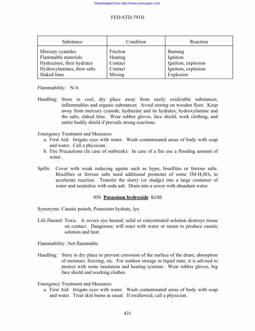
FED-STD-791D
Con Rea
Substance dition
ction
s Mercury cyanideFlammable materials Hydrazines, their hydrates
Contact Contact Hydroxylamines, their salts
Slaked lime
Friction Heating
Mixing
explognition, explo
Burning Ignition Ignition, sion IExplosion
sion
F H place away oxidizable s
s and organic substance on wooden flaway from mercury cyanide, hydrazin
mergency Tre
b. Fire Pwater
pills: Cover with weak reducing agents such as hypo, bisulfites or ferrous salts.
eed additional promoter of some 3M-H2SO4 to
lammability: N/A
andling: Store in inflammable
cool, dry from easily ubstances, s. Avoid storing
e and its hydrates, hydroxylamoor. Keep
ine and the salts, slaked lime. Wear rubber gloves, face shield, work clothing, and entire bodily shield if prevails strong reactions.
atment and Measures: Ea. First Aid: Irrigate eyes with water. Wash contaminated areas of body with soap
and water. Call a physician. recautions (In case of outbreak): In case of a fire use a flooding amount of
.
SBisulfites or ferrous salts naccelerate reaction. Transfer the slurry (or sludge) into a large container of water and neutralize with soda ash. Drain into a sewer with abundant water.
056 Potassium hydroxide KOH Synonyms: Caustic potash, Potassium hydrate, lye.
ard: Toxic. A severe eye hazard; solid or concentrated solution destroys tissue on contact. Dangerous; will react with water or steam to produce caustic
Life Haz
lammability: Not flamm
face of the drum, absorption
f
mergency Treatment and Measures: a. First Aid: Irrigate eyes with water. Wash contaminated areas of body with soap
and water. Treat skin burns as usual. If swallowed, call a physician.
solution and heat. F able.
andling: Store in dry place to prevent corrosion of the surHof moisture, freezing, etc. For outdoor storage in liquid state, it is advised to protect with some insulation and heating systems. Wear rubber gloves, big ace shield and working clothes.
E
431
Downloaded from http://www.everyspec.com
FED-STD-791D
b. Fire Precautions (In case of outbreak): Use large volume of water, but do not splash its solution.
S
t and remove with a broom in a large b lute with water te acid ewer with sufe with dilute acid. Wipe with mo ator.
to a sewer with sufficient water.
pills: a. For solid: Collec ucket. Di
and neutralize with dilu . Drain into a s ficient water. b. For solution: Neutraliz p or use water aspir
Drain in
057 Potassium Hydrogen Phthalate H00CC6H4COOK
Life Hazard Flammabili
Em
c. cautions (In case of outbreak):
Synonyms:
s:
ty: Handling:
ergency Treatment and Measures: a. Hygienic Precautions: b. First Aid:
Fire Pre Spills:
058 Potassium Iodide KI Synonyms:
o 0.01% in table salt).
Handling:
asures:
A
Spills:
Life Hazard: Low toxicity; dietary supplement (up t Flammability:
Emergency Precautions and Me
a. Hygienic Precautions: b. First id: c. Fire Precautions (In case of outbreak):
432
Downloaded from http://www.everyspec.com
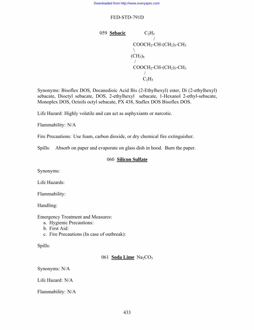
FED-STD-791D
059 Sebacic C2H5 /
COOCH2-CH-(CH2)3-CH3\
/
C2H5
ynonyms: Bisoflex DOS, Decanedioic Acid Bis (2-Ethylhexyl) ester, Di (2-ethylhexyl) octyl sebacate, DOS, 2-ethylhexyl sebacate, 1-Hexanol 2-ethyl-sebacate,
onoplex DOS, Octoils octyl sebacate, PX 438, Staflex DOS Bisoflex DOS.
ife Hazard: Highly volatile and can act as asphyxiants or narcotic.
lammability: N/A
ire Precautions: Use foam, carbon dioxide, or dry chemical fire extinguisher.
Sp evaporate on glass dish in hood. Burn the paper.
n Sulfate
(CH2)8 /
COOCH2-CH-(CH2)3-CH3
Ssebacate, DiM L F F
ills: Absorb on paper and
060 Silico Synonyms:
Life Hazards:
:
tment and Measures: a. Hygienic Precautions:
: c. Fire Precautions (In case of outbreak):
Sp
e
Flammability Handling: Emergency Trea
b. First Aid
ills:
061 Soda Lim Na2CO3
N/A
ife Hazard: N/A
Flammability: N/A
Synonyms: L
433
Downloaded from http://www.everyspec.com

FED-STD-791D
Handling: N/A Emergency Treatment and Measures:
a. Hygienic Precautions: N/A b. First Aid: N/A c. Fire Precautions (In case of outbreak): N/A
062 Sodium carbonate
Spills: N/A
Na2CO3
ife Hazard: Low health hazard, is an irritant.
lammability: N/A
andling: Keep containers closed to store. A hygroscopic material. Wear rubber
First Aid: Flush eyes with water p and water. If swallowed, call a physician.
pills: Sweep into a beaker. Dilute with sufficient water. Add soda ash. Mix
and neutralize with 6M-HCl. Drain into the sewer with abundant water. n: Cover with soda ash. After mixing, transfer into a beaker containing
water. Neutralize with 6M-HCl. Drain into a sewer with abundant water.
063 Sodium chloride
Synonyms: Soda ash, Crystal carbonate. L F H
gloves, safety glass and coveralls. Emergency Treatment and Measures:
. Wash skin with soa
S
a. For solid:
b. For solutio
NaCl
Sy t, Halite, Sea salt. Lif
y: N/A
Handling: Store in dry area, is
e: a. For solid: Collect, dilute with water, and drain into the sewerwith sufficient water.
Wipe with mop or use water aspiration. Drain into the sewer with sufficient water.
nonyms: Salt, Common sal
e Hazard: Low health hazard. Flammabilit
a hydroscopic material. Spills and Leakag
b. For solution:
434
Downloaded from http://www.everyspec.com
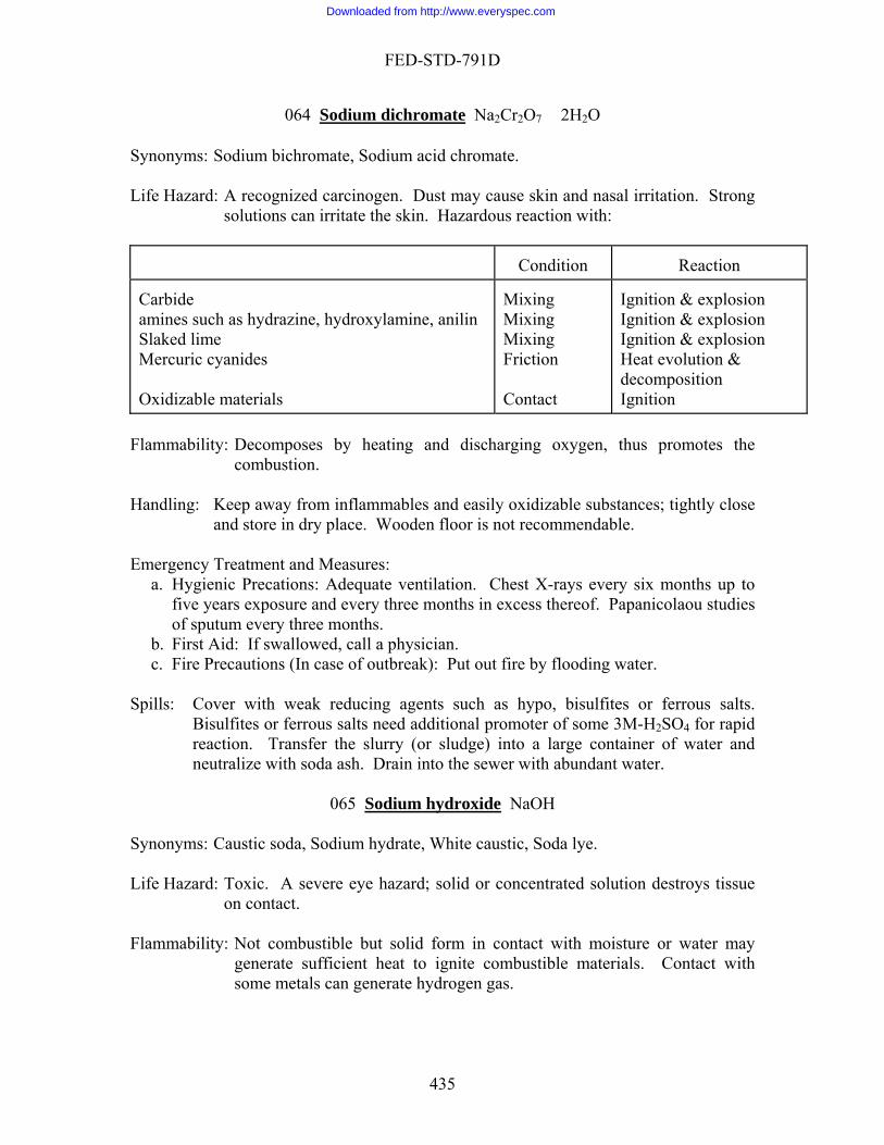
FED-STD-791D
064 Sodium dichromate Na2Cr2O7 � 2H2O
m acid chromate. Lif ized carcinogen. Dust may cause skin and nasal irritation. Strong
ous reaction with:
Condition
Reaction
Synonyms: Sodium bichromate, Sodiu
e Hazard: A recognsolutions can irritate the skin. Hazard
Carbide
Mixing Mixing Friction Contact
Ignition & explosion Ignition & explosion Ignition & explosion Heat evolution & decomposition Ignition
Mixing
amines such as hydrazine, hydroxylamine, anilinSlaked lime Mercuric cyanides Oxidizable materials
Flammability: Decomposes by heating and discharging oxygen, thus promotes the
combustion. Handling: Keep away from inflamma
and store in dry place. Wobles and easily oxidizable substances; tightly close oden floor is not recommendable.
a. Hygienic Precations: Adequate ventilation. Chest X-rays every six months up to ars exposure and every three months in excess thereof. Papanicolaou studies
pills us salts.
Bisulfites or ferrous of some 3M-H2SO4 for rapid reaction. Transfer t arge container of water and
sewer with abundant water.
Sodium hydroxide
Emergency Treatment and Measures:
five yeof sputum every three months.
b. First Aid: If swallowed, call a physician. c. Fire Precautions (In case of outbreak): Put out fire by flooding water.
: Cover with weak reducing agents such as hypo, bisulfites or ferroSsalts need additional promoter he slurry (or sludge) into a l
neutralize with soda ash. Drain into the
065 NaOH
oda, Sodium hydrate, White caustic, Soda lye.
entrated solution destroys tissue
Synonyms: Caustic s Life Hazard: Toxic. A severe eye hazard; solid or conc
on contact. Flammability: Not combustible but solid form in contact with moisture or water may
generate sufficient heat to ignite combustible materials. Contact with some metals can generate hydrogen gas.
435
Downloaded from http://www.everyspec.com

FED-STD-791D
Handling: Protect ag dry place. Protect against moisture and water. Separate from acids, metals, explosives, organic
ical goggles or full face shield, mechanical filter respirator, rubber gloves, aprons and boots.
Emergency Ta. Hygienic Precautions: Personal cleanliness. b. First Aid: Irrigate eyes with water. Wash cont eas f body p
and water. Treat skin burns as usual. If swallowed, call a physician. Precautions (In case of outbreak): Flood w r, using
S
ove with a broom in a la ket. r th dilute acid. Drain into a sewer with sufficien
e with HCl. Wipe with m . Drain
066 Sodium Sulfate
ainst physical damage of container. Store in
peroxides and easily ignitible materials. Wear chem
reatment and Measures:
aminated ar o with soa
c. Fire ith wate care not to splatter or splash this material.
pills: a. For solid: Collect and rem rge buc Dilute with wate
and neutralize wib. For solution: Neutraliz
t water. op or use water vacuum
into the sewer with sufficient water.
Na2SO4
highly toxic SOx when heated to decomposition.
Fla Ha
m
c. Fir
pills:
067
Synonyms: Life Hazards: Is an irritant. Can emit
mmability: Not Flammable.
ndling: Is a hygroscopic material.
E ergency Treatments and Measures: a. Hygienic Precautions: N/A b. First Aid: Ingestion, treatment is symptomatic and supportive, call a physician.
e Precautions (In case of outbreak): N/A
Wash down the drain with excess water. S
Sodium Thiosulfate Na S 0 � 52 2 3 H20
Handling:
ynonyms: Hyposodium subsulfite. S
Life Hazards: Low toxicity; used as food additive up to 0.l9. Flammability:
436
Downloaded from http://www.everyspec.com
FED-STD-791D
Emergency Treatment and Measures: nic Precautions. id.
recautions (In case of outbreak).
a. Hygieb. First Ac. Fire P
Spills:
068 Sulfuric acid H2SO4 Sy
ife Hazard: Contact with the body tissue results in rapid tissue destruction, causing severe burns. Threshold limit value of fumes or mist, 1 mg/m3 moderate
es. Flamm eactive and capable of igniting finely divided
combustible materials on contact. Reacts violently with water and organic materials with y hazardous in contact with many materials. Attacks and corrodes many metals by releasing hydrogen.
r. Separate from carbides, chlorates, fulminates, nitrates, picrates, powdered
ible materials. Wear rubber gloves, chemical goggles, rubber boots and chemical cartridge respirator.
mergency Treatment and Measures: te ventilation. Preclude from exposure those
iseases. ap
o not induce vomiting. c. Fire Precautions (In case of outbreak): Fire involving small amount of
itable dry chemical. Use water on combustibles burning in vicinity of this material but use care as water applied directly to this ac ttering.
te or an equal mixture of soda ash and slaked lime. After mixing, add water if necessary to form a slurry.
069 Sulfurous Acid
nonyms: Oil of vitriol, Dipping acid, Battery Acid, Fertilizer Acid.
L
fire hazard, by chemical reaction; a powerful oxidizer; can ignite upon contact with combustibles. When heated, it emits highly toxic fum
ability: Not flammable but highly r
evolution of heat. Extremel
Handling: Protect containers against physical damage and prevent contacts with wate
metals and combust
E
a. Hygienic Precautions: Adequaindividuals with pulmonary d
b. First Aid: Irrigate eyes with water. Wash contaminated areas of body with soand water. If swallowed, call a physician. D
combustibles may be smothered with su
id results in evolution of heat and causes spla Spills: Cover with sodium carbona
H2SO3
ynonyms: N/A
ife Hazard: Highly toxic by ingestion and inhalation; strong irritant to tissue.
S L
437
Downloaded from http://www.everyspec.com
FED-STD-791D
Flammability: N/A Ha self-contained breathing apparatus, eye goggles, rubber gloves, and
Treatment and Measures:
First Aid: If swallowed, call a
ndling: Wearrubber apron.
Emergency
physician. Spills: N/A
070 Tannic acid C76H52O46 Synonyms: G
ife Hazard: Moderately toxic by ingestion and inhalation. Combustible. Suspected
Flammability: Handling: Avoid skin contact and inhalation.
First Aid:
pills: Absorb on paper. Burn in a hood.
allotannic acid, Tannin, Glycerite.
Lcarcinogen.
Flash point 200°C, autoignition temperature 200°C.
Emergency Treatment and Measures: N/A
If swallowed, call a physician.
S
071 Teflon Sy Lif
Flamm
a. Hygienic Precautions: Nb. First Aid: N/A
tions (In case of outbreak): N/A
nonyms: Polytetra fluoroethylene.
e Hazards: When heated to above 400 C, it decomposes to yield highly toxic fumes of fluorides.
ability: N/A Handling: N/A
Emergency Treatment and Measures: /A
c. Fire Precau Spills: Bury in a landfill well away from streams, rivers, or wells.
438
Downloaded from http://www.everyspec.com

FED-STD-791D
072 Tetrachloroethylene Cl2C=CCl2
ene.
udgement may occur at vapor exposures from 300 ppm to 1000 ppm. Dizziness, drowsiness, loss of consciousness and
asing levels of exposure. When involved in fire, tetrachloroethylene emits highly toxic and irritating fumes of chlorides, a suspected carcinogen.
Flammability: The compound or may decompose at high temperature such as open flame, red-heated materials, with evolution of
carbon monoxide, phosgene.
Do not store in ill-ventilated cellars and hollow places owing to high vapor density. Wear safety goggles, gas mask, rubber gloves. Adequate
a. Hygienic Precautions: Examine liver and kidneys periodically. Preclude from es of heart, liver, kidneys and lungs.
b. First Aid: Irrigate eyes with water. Wash contaminated areas of body with soap a physician. Administer oxygen for
oxygen-shortage.
pills: Absorb on paper and evaporate on a glass dish in hood. Burn the paper. The compound should be redistilled and reused.
Ethyl Lead
Synonyms: Perchloroethylene. Ethylene tetrachloride, Nema, Carbon dichloride,
Tetracap, Percl Life Hazard: Incoordination and impaired j
even death can occur at incre
has no flash point. Vap
poisonous gases such as chlorine, Handling: Store in a closed container in a cool place. Protect against direct sunlight.
ventilation. Emergency Treatment and Measures:
exposure those individuals with diseas
and water. If swallowed, call
S
073 Tetra Pb(C2H5)4
ife Hazards: Powerful poison and a solvent for fatty materials. Suspected carcinogen.
lammability: Flash point (85°C), Decomposes above 110°C. Violently explodes when ed to more than l70°C.
d to sunlight or allowed to evaporate. Separate
Em
a. Hygienic Precautions: Avoid skin contact. : wash immediately
with kerosene or similar petroleum distillate followed by soap and water.
Synonyms: Lead tetraethyl, TEL.
L F
heat Handling: Decomposes when expose
from halogenated compounds or oxidzing agents.
ergency Treatments and Measures:
b. First Aid: Ingestion: induce vomiting, call a physician Skin
439
Downloaded from http://www.everyspec.com
FED-STD-791D
c. Fire Precautions (i ry chemicals, or carbon dioxide fire extinguisher.
Spills: Absorb the spills with paper towels or like materials. Place in a hood to evaporate. Dispose by burning the towel.
n case of outbreak): Use water, foam, d
074 Toluene C6H5Cl
oluol, Methylbenzene, Phenylmethane, Methacide. Synonyms: T
ife Hazard: A recognized carcinogen. Eye and respiratory irritant. Extreme inhalation
lito
andling: Protect containers against physical damage. Outdoors or detached or isolated
door storage should be in a standard flammable
Emer
a. ns: Physical examinations of exposed personnel annually \with special attention to eyes and nervous system, and including complete blood count
dis
and water. An expo mediately to fresh air and kept warm and quiet. If breathing has stopped, artificial respiration should be
ot induce vomiting, call a physician. Eyes; flush with water. Skin: wash with soap and water.
chemical or foam fire extinguishers.
Spills: Spills h is then placed in an iron pan to evaporate it in a hood. Then burn the paper down.
Lof vapors may cause death by paralysis of the respiratory center. Threshold
mit value, 200 parts per million. Dangerous, when heated, it emits highly xic fumes; can react with oxidizing materials.
Flammability: Flash point 4.4°C (closed cup); ignition temperature 536°C; flammable
limits 1.4-6.7%. Vapors may travel considerable distance to a source of ignition and flash back.
Hstorage is preferable. Inliquid storage room. Wear chemical goggles, chemical cartridge respirator or self-contained breathing apparatus and impermeable rubber gloves.
gency Treatment and Measures: Hygienic Precautio
and studies of liver function. Preclude from exposure those individuals with eases of central nervous system and liver.
b. First Aid: Irrigate eyes with water. Wash contaminated areas of body with soap sed person should be removed im
commenced. Ingestion: do n
c. Fire Precautons (In case of outbreak): Use water spray, carbon dioxide, dry
are absorbed on paper whic
075 1,1,1-Trichloroethane CH3 C C13
ene, Ethylidyne-chloride. Lif
s and
Synonyms: Methylchloroform, Chloroth
e Hazard: Incoordination and impaired judgement may occur at vapor exposures from 500 ppm - 1000 ppm. Dizziness, drowsiness, loss of consciousnes
440
Downloaded from http://www.everyspec.com
FED-STD-791D
even death can occur at increasing levels of exposure. When involved in fire, 1,1,1-trichloroethane emits highly toxic and irritating fumes.
b
andling & Storage: Do not store in aluminum containers. Wear safety goggles and rubber glo
a. Hygienic Precautions: Physical examinations of exposed personnel annually,
individb. First A
and wa renaline. Ingestion: have victim drink water and induce vomiting, call a physician.
fire extin
pills: Absorb on paper. Evaporate on a glass dish in hood. Burn the paper in hood.
Flamma ility: Autoignition temperature 500°C, flammable limits in air 7-l8%.
Hves.
Emergency Treatment and Measures:
including studies of liver and kidney function. Preclude from exposure those uals with diseases of liver and kidneys. id: Irrigate eyes with water. Wash contaminated areas of body with soap ter. Inhalation: oxygen, if necessary. No Ad
c. Fire Precautions (in case of outbreak): Use dry chemical, foam, or carbon dioxide guisger.
S Cl
| 076 1,1,2-Trichloro-1,2,2-trifluoroethane CF-CF2-Cl
| Cl
Sy Life H Fla Hand Emer
b. has occured, flush area with warm water. If swallowed, call a physician.
Spills: reused.
nonyms: Trifluorotrichloroethane, Freon-113, Freon TF.
azard: Tolerance, 1000 ppm in air, poisonous gases may be produced in fire.
mmability: Not flammable.
ling: Wear safety glasses, working gloves.
gency Treatment and Measures: a. Hygienic Precautions: Wear rubber gloves and apron. Adequate ventilation.
First Aid: Skin contact: if frostbite
The compound should be redistilled and
077 Valeric Acid CH3(CH2)3 COOH
Synonyms: Pentanic acid. Life Hazard: A toxic material.
441
Downloaded from http://www.everyspec.com

FED-STD-791D
Flammability
andling: A corrosive material.
mergency Treatment and Measures:
b. First Aid: N/A c. Fire Precaution (In case of outbreak): Use alcohol foam, carbon dioxide or dry
Spills
: Flashpoint (88°C)
H E
a. Hygienic Precaution: N/A
chemical fire extinguishers.
: Absorb on paper, then burn in a hood.
078 Xylene C6H4(CH3)2
yms: Xylol Synon Life H ause headache and dizziness. Liquid irritates eyes and skin. If
taken into lungs, causes severe coughing, distress and rapidly developing ,
headache, and coma; can be fatal. Kidney and liver damage can occur. Flammability: Handling: Keep vapors away fr
b. First Aid: Inhalation: remove to fresh air, administer artifical respiration and a doctor. Ingestion: Do not induce vomiting, call a
doctor. Eyes contact: flush with water for l5 min. Skin contact: wipe off and wash
c. Fire Precaution (In case of outbreak): Use foam, carbon dioxide, or dry chemical
Sp
079 Barium Carbonate
azards: Vapors c
pulmonary edema. If ingested, causes nausea, vomiting, cramps
Flash point (29°-46°C), autoignition temperature (469°-528°C).
om open flames. Emergency Treatments and Measures:
a. Hygienic Precautions: Adequate ventilation, rubber gloves.
oxygen if necessary, call
with soap and water.
fire extinguisher.
ills: Absorb on paper, then burn in a hood.
BaCO3
ynonyms: N/A
ife Hazard: N/A
lammability: N/A
Handling: N/A
S
L F
442
Downloaded from http://www.everyspec.com

FED-STD-791D
Emergency Treatment and Measures: a. Hygienic Precautions: N/A
c. Fire Precautions (In case of outbreak): N/A
Sp
b. First Aid: N/A
ills: N/A
080 Chromium Trioxide CrO3
ynonyms: N/A
ife Hazard: N/A
lammability: N/A
andling: N/A
Emergency Trea. Hygienicb. First Aidc. Fire Precautions (In case of outbreak): N/A
pills: N/A
081 Nickelous Chloride
S L
F H
atment and Measures: Precautions: N/A : N/A
S
NiCl2
ynonyms: N/A Lif Flamm Ha
mergency Treatment and Measures:
b. First Aid: N/A c. Fire Precautions (In ca
082 Silver Nitrate
S
e Hazard: N/A
ability: N/A
ndling: N/A
Ea. Hygienic Precautions: N/A
se of outbreak): N/A Spills: N/A
AgNO3 Synonyms: N/A Life Hazard: N/A
443
Downloaded from http://www.everyspec.com
FED-STD-791D
Flammability: N/A Ha
mergency Treatment and Measures: recautions: N/A
b. First Aid: N/A c. Fire Precautions (In ca
ndling: N/A
Ea. Hygienic P
se of outbreak): N/A Spills: N/A
444
Downloaded from http://www.everyspec.com

FED-STD-791D
APPENDIX A AUGUST 24, 2006
CITED IN EACH TEST METHOD ME ATERIALS
LIST OF MATERIALS
THOD NAME OF THE TEST M
103.6 Color of gasoline 1. gasoline (reference) 202.1 Cloud intensity at low
temperature 1.Methanol- glycerol 2.barium Chloride 3. Sulfuric acid 4.Sodium hydroxide 5. Distilled water
203.1 Pour stability of lubricating oils 1. engine crankcase oil 313.3 Penetration of lubricating greases
after prolonged working 1. grease to be tested
335.3 Gear wear 1.Dry cleaning solvent (MIL-PRF-680B, Type 1) 2.Petroleum ether(O-E-751) 3.Di-2 ethylhexyl sebscate, commercial grade 4.Test gear set brass and steel
350.2 Evaporation loss of lubricating greases and oils (high temperature)
1. 1,1-Trichloroethane, Technical, inhibited (Methyl Chloroform) ASTM D 4126 2. Tissue Facial
352.1 Effect of evaporation on flammability
1.Pipe cleaner
353.1 Evaporation 1. None 361.4 Stroking properties of hydraulic
brake fluids 1.Ethyl alcohol (ACS) 2 Crocus cloth 3.Wheel cylinder assemblies 4. Master cylinder assembly 5. Rubber cups 6.Wheel cylinder pistons 7. Master cylinder pistons
500.1 Induction system deposit(ISD) tendencies of motor gasoline
1. n-Hexane, ACS reagent grade 2. Toluene, ACS reagent grade 3. Acetone, ACS reagent grade
550.1 Emulsification tendencies of petroleum fuels by multiple contact extractions
1.Cleaning solution,concentrated sulfuric acid saturated with technical grade potassium di-chromate 2. Distilled or deionized water
445
Downloaded from http://www.everyspec.com
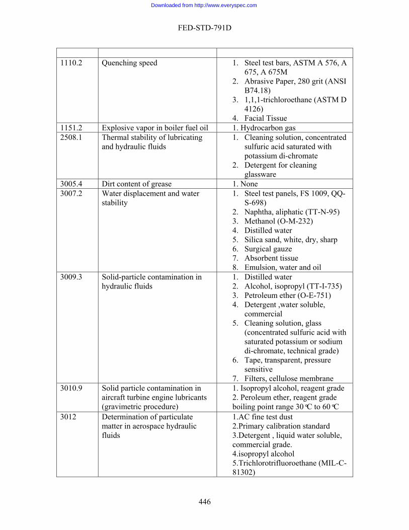
FED-STD-791D
1110.2 Quenching speed 1. Steel test bars, ASTM A 576, A
675, A 675M 2. Abrasive Paper, 280 grit (ANSI
3. 1,1,1-trichloroethane (ASTM D 4126)
issue
B74.18)
4. Facial T1151.2 Explosive vapor in boiler fuel oil 1. Hydrocarbon gas 2508.1 f lubricating n, concentrated
turated with i-chromate
t for cleaning
Thermal stability oand hydraulic fluids
1. Cleaning solutiosulfuric acid sapotassium d
2. Detergenglassware
3005.4 Dirt content of grease 1. None 3007.2 FS 1009, QQ-
2. Naphtha, aliphatic (TT-N-95)
ter arp
e
Water displacement and water stability
1. Steel test panels,S-698)
3. Methanol (O-M-232) 4. Distilled wa5. Silica sand, white, dry, sh6. Surgical gauze 7. Absorbent tissu8. Emulsion, water and oil
3009.3 5)
her (O-E-751) le,
5. Cleaning solution, glass
entrated sulfuric acid with or sodium
, technical grade)
lose membrane
Solid-particle contamination in hydraulic fluids
1. Distilled water 2. Alcohol, isopropyl (TT-I-733. Petroleum et4. Detergent ,water solub
commercial
(concsaturated potassiumdi-chromate
6. Tape, transparent, pressuresensitive
7. Filters, cellu3010.9 Solid particle contamination in
aircraft turbine engine lubricants nt grade
rade (gravimetric procedure)
1. Isopropyl alcohol, reage2. Peroleum ether, reagent gboiling point range 30°C to 60°C
3012 matter in aerospace hydraulic
trifluoroethane (MIL-C-
Determination of particulate
fluids
1.AC fine test dust 2.Primary calibration standard 3.Detergent , liquid water soluble,commercial grade. 4.isopropyl alcohol 5.Trichloro81302)
446
Downloaded from http://www.everyspec.com
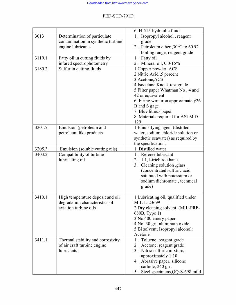
FED-STD-791D
6. H-515-hydraulic fluid 3013 Determination of particulate
contamination in synthetic turbine engine lubricants
nge, reagent grade
1. Isopropyl alcohol , reagent grade
2. Petroleum ether ,30°C to 60°C boiling ra
3110.1 Fatty oil in cutting fluids by infared spectrophotometry 2. l oil, 0.0-15%
1. Fatty oil Minera
3180.2 Sulfur in cutting fluids ACS ent
4.Is5.F . 4 and
6. Firing wire iron approximately26 age
8. Materials required for ASTM D
1.Copper powder, 2.Nitric Acid ,5 perc3.Acetone,ACS
ooctane,Knock test grade ilter paper Whatman No
42 or equivalent
B and S g7. Blue litmus paper
129 3201.7 Emulsion (petroleum and
petroleum like products lled
t ide solution or
1.Emulsifying agent (distiwa er, sodium chlorsynthetic seawater) as required bythe specification.
3205.3 Emulsion (soluble cutting oils) 1. Distilled water 3403.2 Compatibility of turbine
ane
r omate , technical
lubricating oil 1. Referee lubricant 2. 1,1,1-trichlroeth3. Cleaning solution ,glass
(concentrated sulfuric acid saturated with potassium osodium dichrgrade)
3410.1 High temperature deposit and oil degradation characteristics of aviation turbine oils
1.LMI
F-680B, Type 1)
ubricating oil, qualified under L-L-23699
2.Dry cleaning solvent, (MIL-PR
3.No.400 emery paper 4.No. 30 grit aluminum oxide 5.Bi solvent; Isopropyl alcohol: Acetone
3411.1 ity
nts
t grade
:10 ilicone
l specimens,QQ-S-698 mild
Thermal stability and corrosivof air craft turbine engine lubrica
1. Toluene, reagen2. Acetone, reagent grade 3. Nitric-sulfuric mixture,
approximately 14. Abrasive paper, s
carbide, 240 grit 5. Stee
447
Downloaded from http://www.everyspec.com
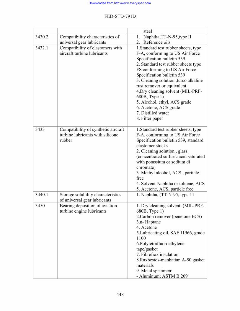
FED-STD-791D
steel 3430.2 of
2. nce oils Compatibility characteristics universal gear lubricants
1. Naphtha,TT-N-95,type II Refere
3432.1 lastomers with aircraft turbine lubricants F-A
bulletin 539 ets type
r Force 9
ion ,turco alkaline
S grade
Compatibility of e 1.Standard test rubber sheets, type , conforming to US Air Force
Specification2. Standard test rubber sheFS conforming to US AiSpecification bulletin 533. Cleaning solutrust remover or equivalent. 4.Dry cleaning solvent (MIL-PRF-680B, Type 1) 5. Alcohol, ethyl, ACS grade 6. Acetone, AC7. Distilled water 8. Filter paper
3433 Compatibility of synthetic turbine lubricants with si
aircraft licone
rubber
pe
n , glass acid saturated
di
3. Methyl alcohol, ACS , particle free4. S 5. Acetone, ACS, particle free
1.Standard test rubber sheets, tyF-A, conforming to US Air Force Specification bulletin 539, standardelastomer stocks 2. Cleaning solutio(concentrated sulfuric with potassium or sodiumchromate)
olvent-Naphtha or toluene, ACS
3440.1 Storage solubility characteristics . Naphtha, (TT-N-95, type 11 of universal gear lubricants
1
3450 nts
solvent, (MIL-PRF-
er (penetone ECS)
ade
8.R -50 gasket t
9. M
Bearing deposition of aviation turbine engine lubrica
1. Dry cleaning680B, Type 1) 2.Carbon remov3.n- Haptane 4. Acetone 5.Lubricating oil, SAE J1966, gr1100 6.Polytetrafluoroethylene tape/gasket 7. Fibrefrax insulation
axbestos-manhattan Ama erials
etal specimen: - Aluminum; ASTM B 209
448
Downloaded from http://www.everyspec.com

FED-STD-791D
-Ti ; 8Mn Annealed, 110ksi (758 MPa) yield strength-UNS R56080
l urity, grade A
tanium
-Si ver; 99.9 p
-Steel; AMS 5040 -Stainless steel; SAE AMS 5518 10. Glass wool fibre 11. 400 grit silicon carbide paper 12. 30 grit aluminum oxide
3452.2 Bearing compatibility of turbine oils
1. Naphtha; Aliphatic (TT-N-95), type11
3456.2 Channeling characteristics of lubricants
None
3457.2 Hydrolytic stability
r (O-E-751) roethane (methyl
1. Emery paper, 00 or finer 2. Litmus paper
the3. Petroleum e. 1,1,1-trichlo4
chloroform), stabilized (MIL-T-81533)
5. n-Hexane , technical grade 6. Sodium sulfate, anhydrous
(ACS) 7. Copper strip (ASTM B
133/ASTM B 272) 3458.1 Low temperature stability test for
oil None
3459.1 Low temperature stability
ic
1. Methyl alcohol-glycerin (technical grade), 1: 1 solution by volume
2. Turbidity standard prepared with barium chloride, sulfuracid, sodium hydroxide, and distilled water
3. Red dye ( National Erie B or equivalent) Bordeaux
3463.1 3463.1Stability of grease in hot
water (water immersion) 1. Distilled water
3465.1 Storage stability test of fluids and lubricants
ommercial
1. Aluminum foil, commercial grade
2. Scouring powder, cgrade
3. Distilled water
3467.1 Storage stability of lubricating 1. None
449
Downloaded from http://www.everyspec.com

FED-STD-791D
grease 3770.1 Homogenity and miscibility of
oils 1. Six reference oils
3480.1 Volatility of blended oils 1. test oils 3500.1 Monobasic acid components of
synthetic ester lubricants by gas chromatography
grade hyleneglycol adipate
, acid
85
e e de
nt grade rylic acid, reagent grade
rade
1.Potassium hydroxide, reagent grade 2. Ethyl alcohol, 95 percent 3. Distilled water . Hydrochloric acid , dilute4
5. Ethyl ether , reagent grade 6. Sodium sulfate, anhydrous,
t reagen7. Dietpolyester
to 80 mesh8.Gas chrom p, 60based washed or equivalent 9.Chloroform, reagent grade 10. Phosphoric acid, reagent grade ,
percent 11. Helium oil free 12. Butyric acid, reagent grade 13. Isovaleric acid, reagent grad14. valeric acid, reagent grad15. Caproic acid, reagent gra
ptylic acid, reage16. He17. cap18. pelargonic acid, reagent g19. Capric acid, reagent grade
3603.5 Swelling of synthetic rubbers
2. Aanh
1. Standard rubber test sheets, asrequired by the specification.
lcohol, ethyl or methyl, ydrous.
3. Filter paper 4. Distilled water
3604.2 Swelling of synthetic rubber by .S pe
n ,
m
l grade
.emery cloth No. 60
aircraft 1 tandard test rubber sheets, tyH or FA 2.Cleaning solutioglass(concentrated sulfuric acid saturated with potassium or sodiudichromate , technical grade) 3.Naphtha,technical grade 4.Toluene , technica.Alcohol, ethyl 5
63710.1 Molybdenum disulfide purity 1.Potassium chlorate
450
Downloaded from http://www.everyspec.com

FED-STD-791D
2.Nitric acid concentrated concentrated
4. Ammonium hydroxide, d
on onium acetate solution
lution, 20 g lead c acid
, 2mL glacial acetic
water nium nitrate solution,
3.Hydrochloric acid ,
concentrate5. Methyl orange indicator soluti6.AmmGlacial acetic acid 8. Lead acetate so
acetate,20mL glacial acitiand distilled water
9. Tannic acid indicator,0.05gtannic acidacid, and 48 mL distilled
10. Ammo30g ammonium nitrate and distilled water
3720.2 Molybdenum disulfide content of lubricating grease
ether (o-E-751
1. n-Hexane, ACS grade 2. Oleic acid , USP grade 3. Petrolium
3722.2 Molybdenum disulfide content of non soap thickened lubricating grease
Cs
or
or
xed
ith one part of sodium carbonate
carbonate, CP
1.Hexane, normal A2. Extraction thimble (double thickness 3.3 x 8.0 cm ) 3.Filter paper (Whatman No. 1 equivalent) 4. Filter paper (Whatman No. 40 equivalent 5.Eschka’s mixture-2 parts calcined(light) magnesia thoroughly miw6.Bromine water, saturated 7. Barium chloride 10 percent 8. sodium carbonate CP 9. Potassium
3816.1 Film thickness of dry solid film lubricants anodized in
trichloroethane (MIL-T-
1. Aluminum alloy test panel (ASTM B 209)accordance with MIL-T-81533
2. 1,1,1-81533)
4001.3 Corrosion protection by coating; Salt spray(fog)test
)
9282) on, ange
r ACS ne
cial
1. Sodium chloride(A-A-592822. Hydrochloric acid (A-A-59282) 3. Sodium hydroxide (A-A-54. Bromthymol blue soluti
indicator, 6.0 to 7.6 pH r5. Distilled wate6. 1,1,1- trichloroetha7. Cleaning tissue, fa
451
Downloaded from http://www.everyspec.com
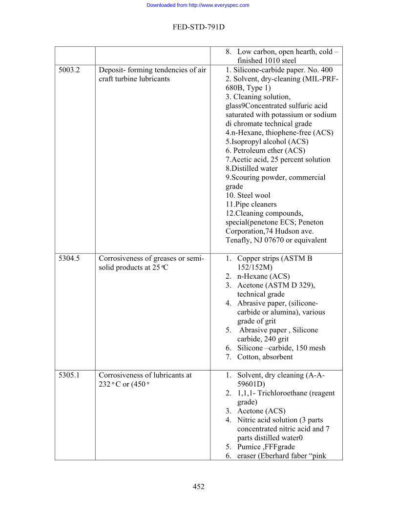
FED-STD-791D
8. Low carbon, open hearth, cold –finished 1010 steel
5003.2 Deposit- forming tendencies of air craft turbine lubricants
o. 400 -cleaning (MIL-PRF-
sulfuric acid
di c4.n-Hexane, thiophene-free (ACS)
6. P7.A
9.S gra
eneton
ivalent
1. Silicone-carbide paper. N2. Solvent, dry680B, Type 1) 3. Cleaning solution, glass9Concentratedsaturated with potassium or sodium
hromate technical grade
5.Isopropyl alcohol (ACS) etroleum ether (ACS) cetic acid, 25 percent solution
8.Distilled water couring powder, commercialde
10. Steel wool 11.Pipe cleaners 12.Cleaning compounds, special(penetone ECS; PCorporation,74 Hudson ave. Tenafly, NJ 07670 or equ
5304.5 Corrosiveness of greases or semi-solid products at 25°C
trips (ASTM B
e (ACS)
ous
cone
7.
1. Copper s152/152M)
2. n-Hexan3. Acetone (ASTM D 329),
technical grade 4. Abrasive paper, (silicone-
carbide or alumina), varigrade of grit
5. Abrasive paper , Silicarbide, 240 grit
6. Silicone –carbide, 150 meshCotton, absorbent
5305.1 Corrosiveness of lubricants at 232° C or (450° )
pink
1. Solvent, dry cleaning (A-A-59601D
2. 1,1,1- Trichloroethane (reagentgrade)
3. Acetone (ACS) 4. Nitric acid solution (3 parts
concentrated nitric acid and 7 parts distilled water0
5. Pumice ,FFFgrade 6. eraser (Eberhard faber “
452
Downloaded from http://www.everyspec.com

FED-STD-791D
pearl” No. 100 or equivalent Cleaning solution, g7. lass
romate, technical
(concentrated sulfuric acid saturated with potassium or sodium di chgrade
8. Distilled water 5306.5 Corrosiveness of emulsifiable
cutting fluids 25
rcial STM D
r
o copper strips (ASTM B electrolytic tough
led, half hard
21, ss
. Two cast iron strips (QQ-I-
9. ips (QQ-S-698), old rolled,
ard
1. Sodium hydroxide solution, containing approximatelypercent NaOH by weight
2. Normal hexane ,comme3. 1,1,1-trichloroethane (A
4126) 4. Distilled wate5. Cleaning tissue 6. Tw
152/152M),pitch, cold roltemper)
7. Two brass strips (ASTM B 1ASTM B 36, cartridge bracomposition 2 half hard temper)
8652,class 20, strip only) Two steel strphysical quality, chalf hard temper-CR half hNo. 2 tempers)
5308.7 Corrosiveness and oxidation stability of light oils (metal squares)
B 1522. Steel, carbon, mild (ASTM
brig,
. Magnesium alloy (SAE AMS
condition H24 or H26.
511lon or linen-,
tal squ7. n carbide,
de or grit e
1. Copper, electrolytic (ASTM/152M)
1008A/1008M, class 1, commercial ht finish
3. Aluminum alloy (ASTM B 209temper T-3 or T-4 44375, 4376, 4377, AZ 31B),
5. Anodes, Cadmium(A-A-26B)
6. Cord (cotton, nylight-weight, clean, for tying me
ares together) Abrasive paper ,(silico
or alumina) various gra8. Abrasive paper, silicon carbid
453
Downloaded from http://www.everyspec.com

FED-STD-791D
2400 mesh
10.11. 1,1,1-trichloroethane (ASTM D 41212. Laboratory filter paper
grit 9. Silicon-carbide grains, 15
Cotton, absorbent
6)
13. Naphtha, aromatic (TT-N-97)
5309.5 of greases (copper strip, 100° C
1.Cann
4. Fine silicon carbide or aluminum
arbide paper er
Corrosiveness opper strip , soft tempered , ealed
2. n-Hexane (ACS grade) 3. Acetone (ACS grade)
grit paper 5. 240 grit silicon- c6. 150 mesh silicon – carbide pap
5321.2 Corrosion of lead by lubricating oils
1.
2. l, copper , Electrolytic
3. ) 4.
6.
Test panel, Chemical-lead (ASTM B 29-55 or equal) Test pane(ASTM B 152/152M) Naphtha, petroleum (TT-N-97Acetone (ASTM D 329)
5. Steel wool Pads, Absorbent- cotton
5329.2 Corrosion Protection (Humidity Cabinet) 2.
3. E 11)
d from open-hearth, “ o. 4
nforming to QQ-S-
1. Naphtha, aliphatic (TT-N-95) Methyl alcohol (O-M-232) Silica sand, white, dry, sharp, (size IAW ASTM
4. Test panelsFS 1009 steel, fabricatekilled ‘’ type low carbon, N, soft –temper, cold rolled sheet or strip co698
5. Surgical gauze 5331.1 Corrosion protection of steel
against sulfurous acid – salt spray by solid film lubricants sulfurous
D 1141) t
1. Steel specimen, carbon steel conforming to fs 1010
2. Synthetic sea water acid test solution (formula ASTM
3. Aluminum oxide cloth 240 gri4. 1,1,1- trichloroethane (MIL-T-
81533) 5. Distilled water (ASTM D 1193,
type 111) 6. Sulfurous acid, ACS
454
Downloaded from http://www.everyspec.com

FED-STD-791D
5341 Fuel system icing inhibitor in hydrocarbon fuels (redox method)
ed ice
ard solution
dard 0.2000 N
complex)
n 1.1000N . Asolution of ate,
cid,
or, and water
1. Crush2. Ethylene glycol monomethyl
ether (EGME) stand3. Potassium di chromate solution,
stan4. Ferroin indicator (1,10
phenanthroline ferrous
5. Ferrous aluminum sulfate solutioferrous ammonium sulfconcentrated sulfuric apotassium dichromate, ferroin indicat
6. Sulfuric acid , concentrated 5414.4 Resistance of grease to fuel
2. 209,
1. Standard test fluid (ASTM D 471, type111) Aluminum strip (ASTM B tempers T-3 or T04 )
5415.1 Resistance of grease to water and a 1:1 water –ethanol solution 1693)
ter
1. Alcohol, ethyl, specially denatured, aircraft (A-A-5
2. Distilled wa6050.1 Nitrate-type ignition improvers in . A
e
ator
3.
diesel fuel 1. Saponification mixture 1N
solution of potassium hydroxidand n-butyl alcohol
2. Diphenylamine (1 percent) solution. A solution of diphenylamine (ACS indicgrade) and sulfuric acid Toluene (ACS Reagent grade)
6052.1 High temperature, high pressure spray ignition
1. Nitrogen gas
6053.1 Manifold ignition test 1. Steel wool 6508.2 Load carrying capacity of SAE J1966
, Type
3. WO-6
lubricating oils (Ryder gear machine)
1. Lubricating oil, 2. Flushing solvents: Stoddard
solvent (MIL-PRF-680B1 and petroleum ether (O-E-751) Test gear, FaFnir
4. o-rings, National No . 622710 5. Shaft seals
6517 High temperature gear load carrying capacity of lubricating oils
1. ng oil, MIL-PRF-7808,
Dry olvent (A-A-
lubricatiSAE J1966, grade 1100 cleaning s
59601D)
455
Downloaded from http://www.everyspec.com

FED-STD-791D
2. Petroleum ether (60-90) ° C
4.
ent
7. chromium trioxide
8.
9. 10.11.
3. Platers wax No.30 grit aluminum oxide
5. Purified crystalline nickelous chloride
6. Hydrochloric acid ,reaggrade Crystallinereagent grade Crystalline silver nitrate reagent grade Barium carbonate Nickel bar stock Lead sheet
12. Reference oil 7501 Low temperature torque test
method for lubricating greases 1.None
7502 Solvent cleaning power by soil test method 2. 0° C
1. Toluene CP at least 99% Thermometer ,range 5
10000 Material handling safety
precaution 1. None
456
Downloaded from http://www.everyspec.com
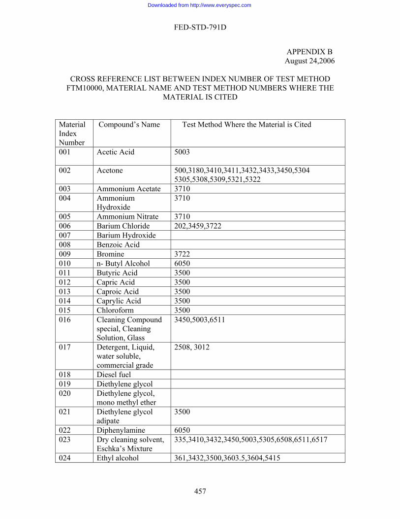
FED-STD-791D
APPENDIX B August 24,2006
CROSS REFERENCE LIST BETWEEN INDEXFTM10000, MATERIAL NAME AND TEST METHOD NUMBERS WHERE THE
MATERIAL IS CITED Material Index Number
Compound’s Name Test Method Whe is Cited
NUMBER OF TEST METHOD
re the Material
001 Acetic Acid
5003
002 Acetone 500,3180,3410,3411,3432,3433,3450,5304 5305,5308,5309,5321,5322
003 Ammonium Acetate 3710 004 A
Hmmonium 3710 ydroxide
005 A itrate 3710 mmonium N006 Barium Chloride 202,3459,3722 007 Barium Hydroxide 008 Benzoic d Aci009 Bromine 3722 010 n- Butyl Alcohol 6050 011 Butyric Acid 3500 012 Capric Acid 3500 013 Caproic Acid 3500 014 Caprylic Acid 3500 015 Chloroform 3500 016 Cleaning Compound
special, Cleaning Solution, Glass
3450,5003,6511
017 Detergent, Liquid, water soluble, commercial grade
2508, 3012
018 Diesel fuel 019 Diethylene glycol 020 Diethylene glycol,
mono methyl ether
021 Diethylene glycol adipate
3500
022 Diphenylamine 6050 023 Dry cleaning solvent,
Eschka’s Mixture 335,3410,3432,3450,5003,5305,6508,6511,6517
024 Ethyl alcohol 361,3432,3500,3603.5,3604,5415
457
Downloaded from http://www.everyspec.com

FED-STD-791D
025 Ethyl th 0,36 3.5 e er 350 0026 Ethylene glycol 027 Ethylene glycol 5341
monomethyl ether 02
sulfate, Freon-12 8 Ferrous ammonium 5341
029 Gasoline Glacial Acetic Acid
103
030 Glycerin 031 n-Haptane 3450 032 Heptylic acid 3500 033 n-Hexane 500,3457,3720,3722,5003,5304,5306,5309 034 Hydrochloric acid 3500,3710,40014001,6517 035 Isooctane 3180 036 Isopropyl alcohol 3009,3010, 3012,3013,3410,5003, 037 Kerosine 038 Lead acetate 3710 039 Magnesium oxide 040 Mercuric iodide 5327 041 Methyl alcohol
Methyl-Alcohol-Glycerine
202,3007,3433,3603.5,5329
042 Methyl ethyl ketone 043 Methyl orange 3710 044 Naphtha 3007,3013,3430,3433,3440,3452,3604,5308,5321,
5329 045 Neopentyl Polyol
Ester
046 Nitric acid Nitric-Sulfuric Acid Mixture
3180,3710,5305
047 N0 –Chromix Cleaning solution
048 3720 Oleic acid 049
ther 3500 Pelargonic acid,
Petroleum E050 1,10- phenanthroline 341 5051 Phenolphthalein 052 3500 Phosphoric acid 053 Potassium carbonate 722 3500,3054 Potassium chlorate 3710 055 Potassium
Dichromate 5341
056 Potassium hydroxide 6050 057 Potassium Hydrogen
458
Downloaded from http://www.everyspec.com
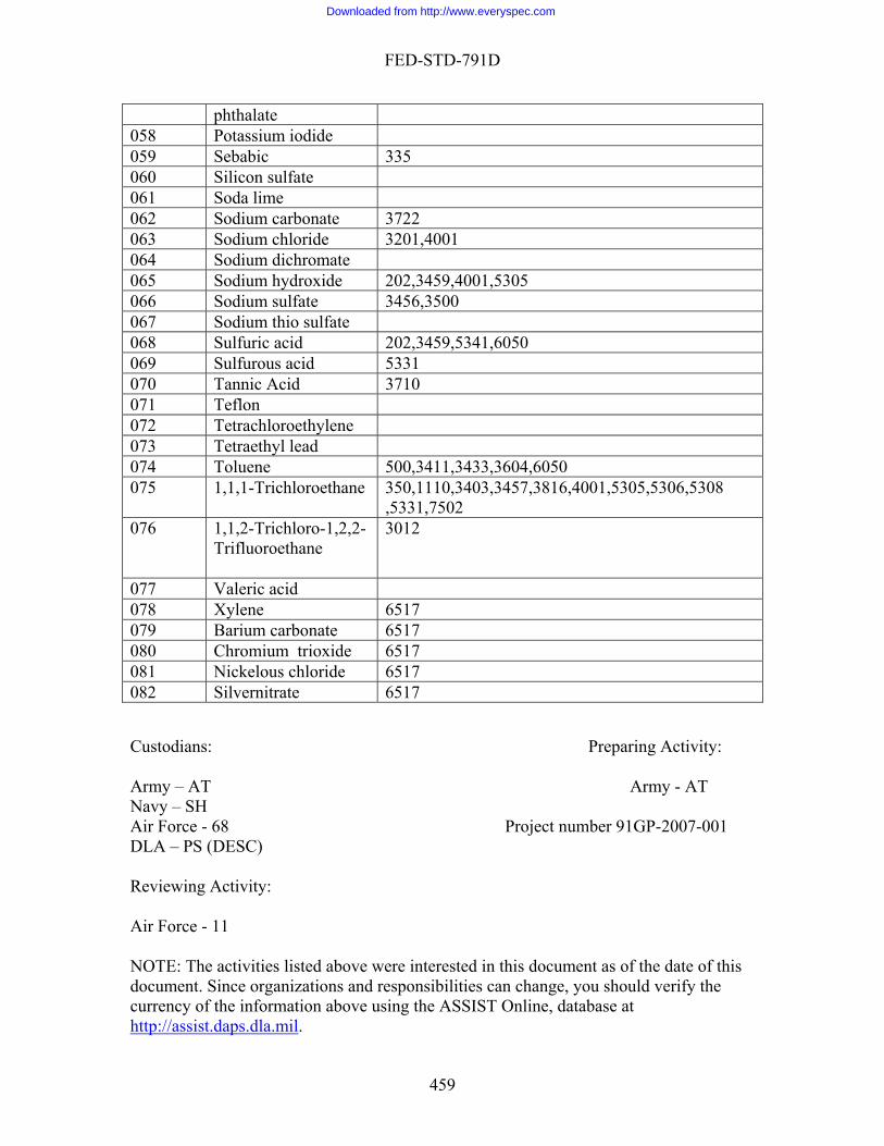
FED-STD-791D
phthalate 058 Potassium iodide 059 Sebabic 335 060 Silicon sulfate 061 Soda lime 062 3722 Sodium carbonate063 Sodium chloride ,4001 3201064 Sodium dichromate 065 Sodium hydroxide 02,3459,4001,5305 2066 Sodium sulfate 500 3456,3067 Sodium thio sulfate 068 Sulfuric acid 202,3459,5341,6050 069 Sulfurous acid 5331 070 Tannic Acid 3710 071 Teflon 072 Tetrachloroethylene 073 Tetraethyl lead 074 Toluene 500,3411,3433,3604,6050 075 1,1,1-Trichloroethane 10,3403,3457,3816,4001,5305,5306,5308 350,11
,5331,7502 076 1,1,2-Trichloro-1,2,2-
hane 3012
Trifluoroet
077 Valeric acid 078 Xylene 6517 079 Barium carbonate 6517 080 Chromium trioxide 517 6081 Nickelous chloride 6517 082 Silvernitrate 6517
dians: Preparing Activity:
– AT Army - AT – SH orce - Project number 91GP-2007-001 – PS (
wing
orce -
E: The d above were interested in this document as of the date of this ment. Since organizations and responsibilities can change, you should verify the ncy of us e ASSIST Online, database at /assist
Custo
Army NavyAir F 68 DLA DESC) Revie Activity: Air F 11 NOT activities listedocucurre the information above
.daps.dla.miling th
http:/ .
459
Downloaded from http://www.everyspec.com