metrology & measurement lab me-594 -...
TRANSCRIPT

Metrology & Measurement Lab
ME-594
Contacts:
Mail: [email protected]
Web: http://www.ajourneywithtime.weebly.com/

Metrology & Measurement Lab
ME-594, Credits: 1
At least 6 experiments to be conducted from the following :
1. Taking measurements using following instruments :
(i) Vernier height & depth gauge, (ii) Dial micrometer, (iii) Thread gauge, (iv) Radius gauge, (v) Filler gauge, (vi) Slip gauge.
2. Measurement of angle of a component using :
(i) Vernier bevel protractor, (ii) angle gauges , (iii) Sine-bar and slip gauges.
3. Checking / measuring parallelism, cylindricity and concentricity of components using dial indicator.
4. Measurement of a specific dimension for a lot of components, and prepare a histogram from the data obtained.
5. Measurement of surface finish by a Talysurf instrument.
6. Measurement of micro feature of a product (eg. Thread of a bolt or saw etc.) in a profile projector.
7. Determine natural cooling characteristics of a heated object by using a thermocouple.
8. Measurement of air velocity across an air duct using anemometer.
9. Fixing a strain gauge on a cantilevered flat section of steel. Then calibration of it as a force dynamometer using a Wheatstone bridge and loading arrangement.
(NB.: This experiment has to be done over two days– one day for fixing and second day for calibration).

Exp 06: Fixing a strain gauge on a cantilevered flat section of
steel. Then calibration of it as a force dynamometer using a
Wheatstone bridge and loading arrangement.
APPARATUS:
The elements of the sensor in this lab include: (a) the mechanical
system; (b) mechanical to electrical conversion (strain gauge);
(c) a data acquisition system (electronic)
THEORY & Procedure:
Observations Table:
Conclusions:

Sensor analysis
Step1: A cantilever beam as the part which senses deflection due to a load. On it strain gauges will be mounted.
Step 2: Note and record the strain gauge positions
Step3: knowing the information given to you, measure the appropriate parts of the cantilever beam. These will be needed in your calculation.
Step 4. calculate what you expect for deflection of the cantilever beam.

Cantilever Beam Preparation and Strain Gauging
Mounting and Testing the Cantilever Sensor
• Test the connections for continuity and resistance using the strain gauge test module.
• Clamp the cantilever bar to a table with the instrumented portion cantilevered off the edge.
• Connect the leads to the strain indicator, set the gauge factor, Sg, and zero the indicator.
• Calibrate your load cell by hanging different weights from the end and recording the strain indication.
Laying Strain Gauges :


Laying Strain Gauges :
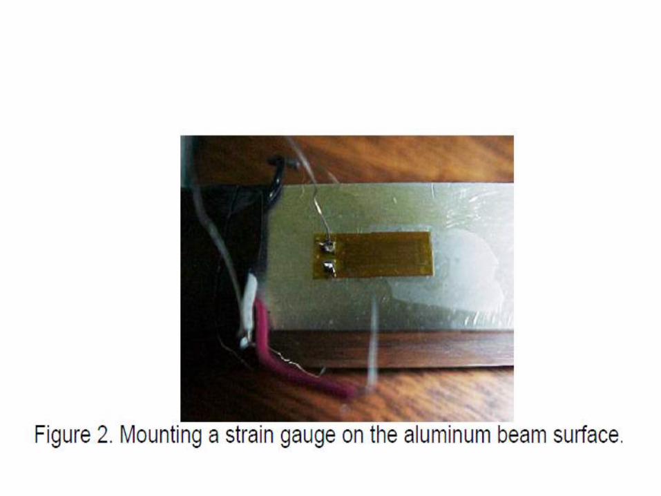
• Use emery paper to sand (roughen) the upper and lower surfaces of the spare cantilever beam near the mid point, l/2, to prepare for surface mounting the strain gauges. A rougher surface enables better fastening of the strain gauge adhesive (epoxy).
• Mount the strain gauges on the abraded sections, one on top and one on
the bottom of the beam. Make sure of two things: (1) to orient each gauge axis along the length of the beam, (2) mount the gauges so that one is directly above the other, this way, as the beam is bent, one gauge measures the tension on the outside of the bend, while the other gauge measures the compression on the inside.
• Solder lead wires to the solder tabs on the gauges for connection to the strain indicator


• A cantilever beam is a structure, which is fixed at one end. It is the basic
sensing element of this sensor. The end of the beam deflects ymax with
increasing load, P. P must be applied at the same point for each load
application. The length of the beam, l, must remain constant for the sensor.
E: modulus of elasticity of the beam; I: second area moment of inertia,
Cantilever beam can be used for measurement up to 10 kg of weight. One end of
the cantilever is fixed, while the other end is freeThe strain developed at the
fixed end is given by the expression: l = length of the beam
t = thickness of the cantilever
b = width of the beam
E = Young’s modulus of the material
The strain developed can be measured by fixing strain gages at the fixed end:
two on the top side of the beam, measuring tensile strain +ε and two on the
bottom measuring compressional strain – ε


Strain Gauge Factor (Sg) • The change in resistance observed in the strain gauge can be
related directly to the change in length of the gauge, which can
be converted to strain, ε.
Where ΔR: change in resistance (ohms) caused by stretching (fancy word for
elongation); Rg: resistance of the strain gauge (ohms); εx: the strain
(microstrain, μstrain) along the axis of alignment of the gauge; Sg: gauge
factor.

Wheatstone Bridge Sensor Configurations
All strain-gauge configurations are based on the concept of a Wheatstone bridge. A
Wheatstone bridge is a network of four resistive legs. One or more of these legs can
be active sensing elements.
The Wheatstone bridge is the electrical equivalent of two parallel voltage divider
circuits. R1 and R2 compose one voltage divider circuit, and R4 and R3 compose the
second voltage divider circuit. The output of a Wheatstone bridge is measured
between the middle nodes of the two voltage dividers.
A change in strain , changes the resistance of the sensing elements in the Wheatstone
bridge.
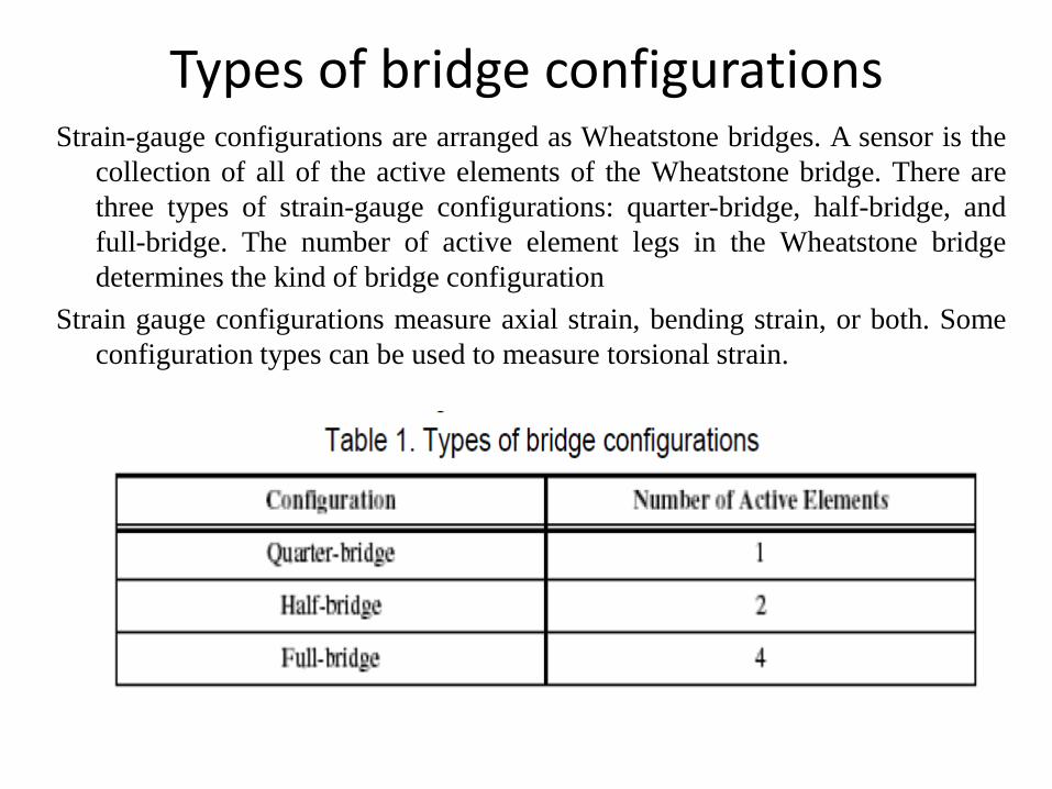
Types of bridge configurations Strain-gauge configurations are arranged as Wheatstone bridges. A sensor is the
collection of all of the active elements of the Wheatstone bridge. There are
three types of strain-gauge configurations: quarter-bridge, half-bridge, and
full-bridge. The number of active element legs in the Wheatstone bridge
determines the kind of bridge configuration
Strain gauge configurations measure axial strain, bending strain, or both. Some
configuration types can be used to measure torsional strain.

Quarter-Bridge “Type I”
A single active strain-gauge element is mounted in the principle direction of axial or bending strain.
A passive quarter-bridge completion resistor (dummy resistor) is required in addition to half-bridge completion.
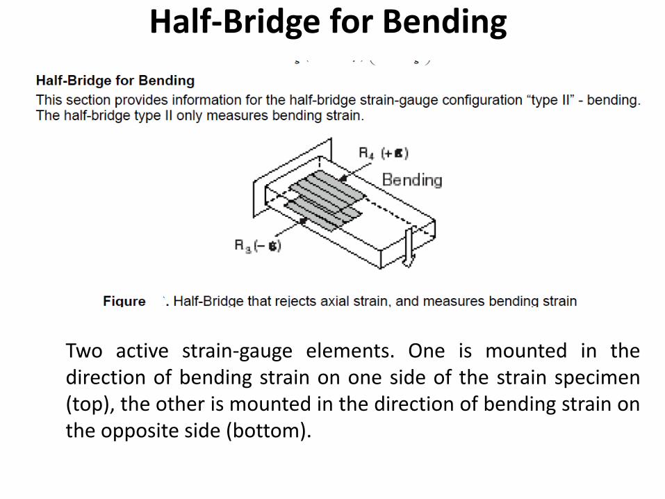
Half-Bridge for Bending
Two active strain-gauge elements. One is mounted in the direction of bending strain on one side of the strain specimen (top), the other is mounted in the direction of bending strain on the opposite side (bottom).