metso neles nd9000 valve controller via foundation ... · the metso valve manager software...
TRANSCRIPT
METSO Neles ND9000 Valve Controller via FOUNDATION Fieldbus to the PlantPAx Process Automation System
Application Technique

Important User Information Solid-state equipment has operational characteristics differing from those of electromechanical equipment. Safety Guidelines for the Application, Installation and Maintenance of Solid State Controls (publication SGI-1.1 available from your local Rockwell Automation sales office or online at http://www.rockwellautomation.com/literature/) describes some important differences between solid-state equipment and hard-wired electromechanical devices. Because of this difference, and also because of the wide variety of uses for solid-state equipment, all persons responsible for applying this equipment must satisfy themselves that each intended application of this equipment is acceptable.
In no event will Rockwell Automation, Inc. be responsible or liable for indirect or consequential damages resulting from the use or application of this equipment.
The examples and diagrams in this manual are included solely for illustrative purposes. Because of the many variables and requirements associated with any particular installation, Rockwell Automation, Inc. cannot assume responsibility or liability for actual use based on the examples and diagrams.
No patent liability is assumed by Rockwell Automation, Inc. with respect to use of information, circuits, equipment, or software described in this manual.
Reproduction of the contents of this manual, in whole or in part, without written permission of Rockwell Automation, Inc., is prohibited.
Throughout this manual, when necessary, we use notes to make you aware of safety considerations.
Allen-Bradley, Rockwell Software, Rockwell Automation, and TechConnect are trademarks of Rockwell Automation, Inc.
Trademarks not belonging to Rockwell Automation are property of their respective companies.
WARNING: Identifies information about practices or circumstances that can cause an explosion in a hazardous environment, which may lead to personal injury or death, property damage, or economic loss.
ATTENTION: Identifies information about practices or circumstances that can lead to personal injury or death, property damage, or economic loss. Attentions help you identify a hazard, avoid a hazard, and recognize the consequence.
SHOCK HAZARD: Labels may be on or inside the equipment, for example, a drive or motor, to alert people that dangerous voltage may be present.
BURN HAZARD: Labels may be on or inside the equipment, for example, a drive or motor, to alert people that surfaces may reach dangerous temperatures.
IMPORTANT Identifies information that is critical for successful application and understanding of the product.
2 Rockwell Automation Publication PROCES-AT021A-EN-P - September 2013

Introduction The purpose of this document is to provide a simple proven step by step guide to integrating and configuring the Metso Neles Valve controller into the Rockwell Automation PlantPAx process Automation System using the 3 process networks. These include HART, FOUNDATION Fieldbus and Profibus PA. This document is intended to provide a tested method to quickly connect to and communicate with the field device. It is not meant to show all of the methods nor is it intended to be a detailed document pertaining to all of the features, capabilities and application of the field devices.
To supply robust system solutions, Rockwell Automation pre-tests many third-party manufactured HART, FOUNDATION Fieldbus, and PROFIBUS PA field devices in the system test laboratory for compatibility with the Rockwell Automation PlantPAx process automation system. Each field device is connected to the PlantPAx system and is subjected to interoperability testing procedures similar to operating procedures in your plant. The results of each field test are recorded in a test report for integration planning purposes.
For this field device, an additional step provides an integration document and interoperability statement for each tested instrument. This integration document provides information on installation, configuration, startup, and operation of the integrated system. The interoperability statement is assurance that the field device meets PlantPAx system interoperability performance measures, as established by Rockwell Automation. Both the integration document and interoperability statement help reduce risk with ease of integration.
The overall purpose of this document is to provide you with proven solutions that combine field instrumentation with fieldbus networks, such as HART, FOUNDATION Fieldbus, and PROFIBUS PA networks, with asset management capabilities and Rockwell Automation’s system capabilities to provide a total engineered solution.
Through pre-engineered integration in support of increasing requirements for plant-wide control, the document offers the following benefits:
• Reduced integration costs throughout engineering, commissioning, and start-up
• Optimized plant availability and output• Ensured product quality and consistency• Optimized traceability to meet regulatory demands• Predictive maintenance through intelligent instruments
Rockwell Automation Publication PROCES-AT021A-EN-P - September 2013 3

For new construction, process improvements at an existing plant, or operating cost reductions, the benefits are:
• Reduces risk, reduces integration costs, and protects investment with pre-engineered interoperability. Both companies believe open systems and standardized interfaces bring maximum benefits.
• Advanced diagnostics with plant-wide control provides better visibility of plant health and easier access to instrument diagnostics, which ultimately leads to faster troubleshooting and improves decision-making.
• Collaborative lifecycle management leads to improvements in design, engineering, and startup and support of plants. This collaboration increases productivity, manages information about instrumentation assets, optimizes plant assets, and results in a complete lifecycle management solution.
Application Overview This document provides a step-by-step approach to integrating a Metso field device via FOUNDATION Fieldbus into a Rockwell Automation PlantPAx process automation system.
The ControlLogix platform provides a robust EtherNet/IP backbone for communication to process fieldbus networks.The PlantPAx architecture uses producer/consumer technology, allowing input information and output status to be shared by all ControlLogix controllers in the system. This integration document assumes you have a working knowledge of ControlLogix systems. For more details regarding the equipment and tasks described in this document see additional resources.
This integration document assumes you have a working knowledge of ControlLogix systems.
This integration document assumes you have a working knowledge of ControlLogix systems. For more details regarding the equipment and tasks described in this document go to the Rockwell Automation Literature library at www.rockwellautomation.com and www.rockwellautomation.com/knowledgebase
The AOP can be downloaded from Rockwell Hiprom at www.hiprom.com.
Section Describes
Application Overview Details about the field instrument and control system.
System Details Specifications on the required hardware and software components.
Installation How to install and connect the instrument, linking device and other components.
Configuration How to:• Configure the 1788-EN2FFR or 1788-CN2FFR linking device.• Configure the field device.
Visualization How to implement and configure a graphical display of device information.
4 Rockwell Automation Publication PROCES-AT021A-EN-P - September 2013

Device files can be downloaded from www.metso.com/valves
or from the FIELDBUS Foundation at www.fieldbus.org.
The following diagram is an example of a PlantPAx system used for testing. It is based on EtherNet/IP network backplane with I/O for HART and 1788-EN2PAR and EN2FFR Linking devices for FF and Profibus PA. The personal computer has the following software packages for programming and configuring the system and field components: RSLogix V20, RSLinx, FactoryTalk View and AssetCentre. Other tools are available from the device vendors such as hand held programmers and software packages.
Rockwell Automation Publication PROCES-AT021A-EN-P - September 2013 5

Device Information Intelligent Valve Controller, Series ND9000
Neles ND9000 is a top class intelligent valve controller designed to operate on any valve and actuator type in all industry areas. With unique performance features, it ensures maximum control accuracy in all operating conditions. The diagnostic capabilities provide the user with valuable information as a basis for predictive maintenance. For more details see ND9000 Installation, Maintenance and operators Instructions (7ND9071en.pdf ) (www.metsoautomation.com/ND9000).
• Enclosure options– ND9100: Anodized aluminum alloy and polymer composite– ND9200: Anodized aluminum alloy and tempered glass– ND9300: Full 316 stainless steel
• Communication options– ND9000H HART– ND9000F, FOUNDATION Fieldbus H1– ND9000P Profibus PA
6 Rockwell Automation Publication PROCES-AT021A-EN-P - September 2013

• Wide coverage of hazardous area approvals (Explosion/Flame proof, Intrinsically safe) – ATEX, IECEx, cCSAus, Inmetro, GOST R
• Single device for double and single-acting actuators, as well as linear and rotary valves
• Simple and fast commissioning (only 4 parameters needed: signal, rotating direction, actuator type, fail safe action)
• 3 types of spool valves for different actuator sizes– Small actuators < 1 dm3 = 2 mm spool valve ≥ 5 Nm3/h / 3 scfm– Medium actuators 1 dm3 - 3 dm3 = 3 mm spool valve ≥ 12 Nm3/h / 7
scfm– Large actuators > 3 dm3 = 6 mm spool valve ≥ 38 Nm3/h / 22 scfm
• The adaptive control algorithm together with the intelligent nozzle / flapper system ensures best control results even under changing process and environmental conditions.– Dead band ≤ 0.1% / hysteresis < 0.5% (according to IEC61514
measured with a diaphragm actuator at moderate constant-load in ambient temperature).
• By continuous monitoring of the supply and actuator pressure– leaks in the control system can be identified and compensated– best control results will be achieved even with external instrumentation
components (volume booster)• Valve specific functions (dead angle, cut-offs and valve characterization)
integrated.• Local user interface enables easy usage of the device
– Parameterization and calibration– Measurements: input signal, valve position, temperature, supply
pressure, actuator pressure difference– All warnings, alarm messages as clear text messages in English, German,
French• Extremely high vibration resistance• Continuous self-monitoring, as well as online, counter and lifecycle
diagnosis enables– rapid detection of faulty components– accurate assessment of the specific valve performance – statement about negative process and environmental influences– assessment of the performance of the superior controller
• All diagnostic data are stored in the device over the entire operating period (up to 25 years)
• The event log stores up to 8000 events (alerts, alarms, notes)• Performance view• Supports FDT/DTM technology
Rockwell Automation Publication PROCES-AT021A-EN-P - September 2013 7

• Advanced offline-tests according IEC61514 / ISA 75.25-2000– Multipoint step response test– Hysteresis test– Valve analysis test– Dead band test
The Metso Valve Manager software graphically displays indexes of the valve, actuator and positioner, as well as indexes of control performance and the application environment. Report will show explanations of the status of each component and guidelines for recommended actions.
Figure 1 - The Performance View of the Metso Valve Manager
8 Rockwell Automation Publication PROCES-AT021A-EN-P - September 2013

Figure 2 - Example Diagnostics Trend on the Device
Figure 3 - Multipoint step response test
Rockwell Automation Publication PROCES-AT021A-EN-P - September 2013 9
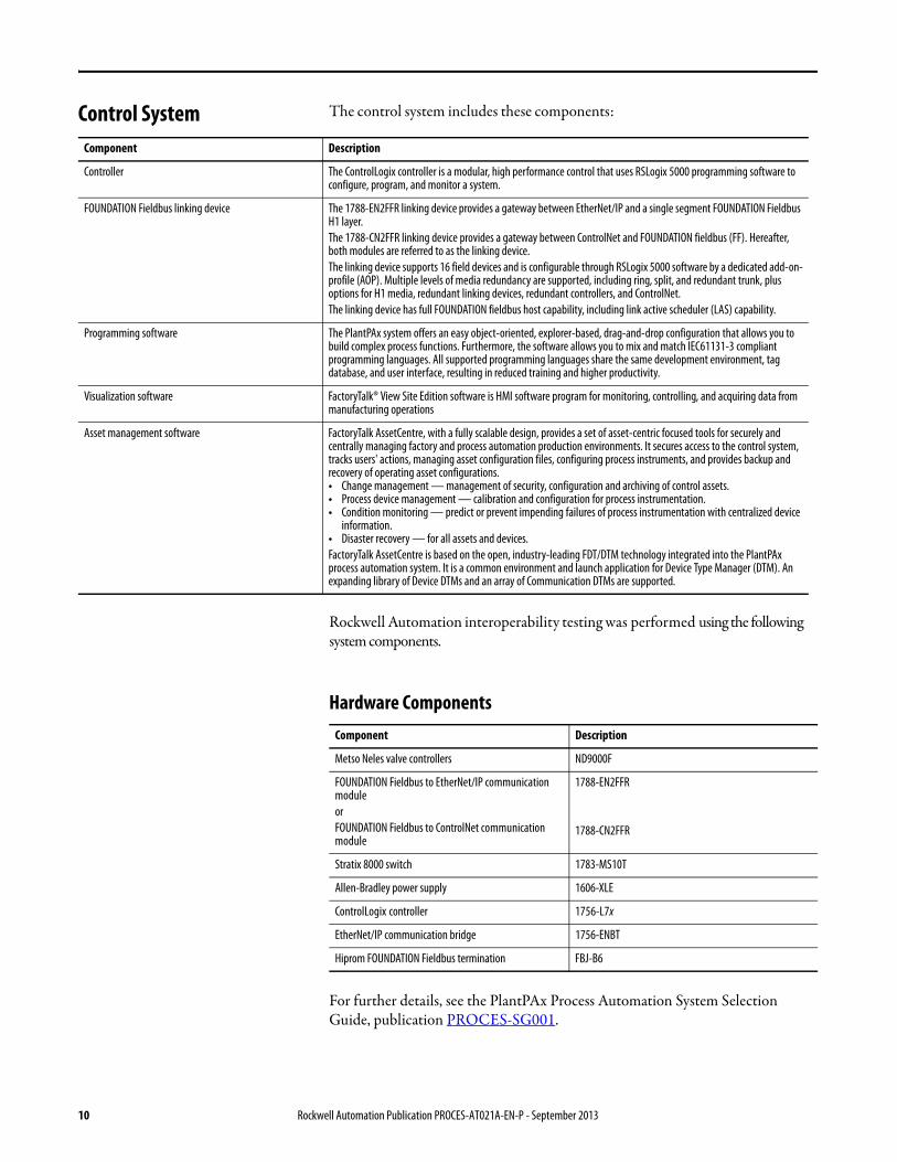
Control System The control system includes these components:
Rockwell Automation interoperability testing was performed using the following system components.
Hardware Components
For further details, see the PlantPAx Process Automation System Selection Guide, publication PROCES-SG001.
Component Description
Controller The ControlLogix controller is a modular, high performance control that uses RSLogix 5000 programming software to configure, program, and monitor a system.
FOUNDATION Fieldbus linking device The 1788-EN2FFR linking device provides a gateway between EtherNet/IP and a single segment FOUNDATION Fieldbus H1 layer.The 1788-CN2FFR linking device provides a gateway between ControlNet and FOUNDATION fieldbus (FF). Hereafter, both modules are referred to as the linking device.The linking device supports 16 field devices and is configurable through RSLogix 5000 software by a dedicated add-on-profile (AOP). Multiple levels of media redundancy are supported, including ring, split, and redundant trunk, plus options for H1 media, redundant linking devices, redundant controllers, and ControlNet.The linking device has full FOUNDATION fieldbus host capability, including link active scheduler (LAS) capability.
Programming software The PlantPAx system offers an easy object-oriented, explorer-based, drag-and-drop configuration that allows you to build complex process functions. Furthermore, the software allows you to mix and match IEC61131-3 compliant programming languages. All supported programming languages share the same development environment, tag database, and user interface, resulting in reduced training and higher productivity.
Visualization software FactoryTalk® View Site Edition software is HMI software program for monitoring, controlling, and acquiring data from manufacturing operations
Asset management software FactoryTalk AssetCentre, with a fully scalable design, provides a set of asset-centric focused tools for securely and centrally managing factory and process automation production environments. It secures access to the control system, tracks users' actions, managing asset configuration files, configuring process instruments, and provides backup and recovery of operating asset configurations.• Change management — management of security, configuration and archiving of control assets.• Process device management — calibration and configuration for process instrumentation.• Condition monitoring — predict or prevent impending failures of process instrumentation with centralized device
information.• Disaster recovery — for all assets and devices. FactoryTalk AssetCentre is based on the open, industry-leading FDT/DTM technology integrated into the PlantPAx process automation system. It is a common environment and launch application for Device Type Manager (DTM). An expanding library of Device DTMs and an array of Communication DTMs are supported.
Component Description
Metso Neles valve controllers ND9000F
FOUNDATION Fieldbus to EtherNet/IP communication moduleor FOUNDATION Fieldbus to ControlNet communication module
1788-EN2FFR
1788-CN2FFR
Stratix 8000 switch 1783-MS10T
Allen-Bradley power supply 1606-XLE
ControlLogix controller 1756-L7x
EtherNet/IP communication bridge 1756-ENBT
Hiprom FOUNDATION Fieldbus termination FBJ-B6
10 Rockwell Automation Publication PROCES-AT021A-EN-P - September 2013

Software Components
For specifications of the engineering workstation (EWS) and operator workstation (OWS), see the Integrated Architecture for Process Control System Recommendations Reference Manual, publication PROCES-RM001.
Connect a ND9000F Foundation FIELDBUS Valve Controller
The ND9000F is powered by the FOUNDATION fieldbus network (IEC 61158-2). The same bus cable is used also for the fieldbus communication. The bus cable is led through a:
• M20 x 1.5 cable gland, or• 1/2 NPT cable gland
Connect the conductors to the terminal strip as shown below.
Figure 4 - ND9000F Terminals
Component Catalog Number
RSLogix 5000 Enterprise Series programming software, Professional editionIncludes:• RSLinx Classic software
9324-RLD700NXENE
FactoryTalk View Site Edition (SE) software (optional) 9701-VWSXXXXXENE
FactoryTalk AssetCentre server 9515-ASTSRVRENE
FactoryTalk AssetCentre process device configuration 9515-ASTPRDCFENE
FieldCare Standard Asset Management software (optional)
—
Rockwell Automation Publication PROCES-AT021A-EN-P - September 2013 11
Assembly Related Parameter Settings
The configuration parameters shall be defined based on valve assembly. Parameters can be set via device DTM or via LUI (local user interface). For details see ND9000 Installation, Maintenance and operators Instructions (7ND9071en.pdf ) (www.metsoautomation.com/ND9000).
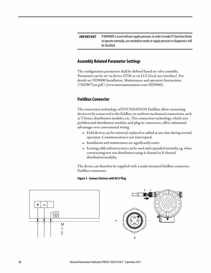
Fieldbus Connector
The connection technology of FOUNDATION Fieldbus allows measuring devices to be connected to the fieldbus via uniform mechanical connections, such as T-boxes, distribution modules, etc. This connection technology, which uses prefabricated distribution modules and plug-in connectors, offers substantial advantages over conventional wiring.
• Field devices can be removed, replaced or added at any time during normal operation. Communication is not interrupted.
• Installation and maintenance are significantly easier.• Existing cable infrastructures can be used and expanded instantly, e.g. when
constructing new star distributors using 4-channel or 8-channel distribution modules.
The device can therefore be supplied with a ready-mounted fieldbus connector. Fieldbus connectors
Figure 5 - Connect Devices with M12 Plug
IMPORTANT If ND9000F is used without supply pressure, in order to make FF function blocks to operate normally, use simulation mode or supply pressure or diagnostics will be disabled.
12 Rockwell Automation Publication PROCES-AT021A-EN-P - September 2013
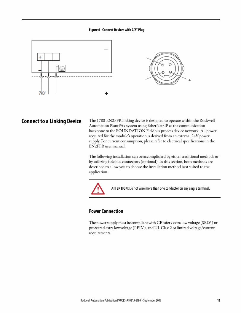
Figure 6 - Connect Devices with 7/8” Plug
Connect to a Linking Device The 1788-EN2FFR linking device is designed to operate within the Rockwell Automation PlantPAx system using EtherNet/IP as the communication backbone to the FOUNDATION Fieldbus process device network. All power required for the module’s operation is derived from an external 24V power supply. For current consumption, please refer to electrical specifications in the EN2FFR user manual.
The following installation can be accomplished by either traditional methods or by utilizing fieldbus connectors (optional). In this section, both methods are described to allow you to choose the installation method best suited to the application.
Power Connection
The power supply must be compliant with CE safety extra low voltage (SELV ) or protected extra low voltage (PELV ), and UL Class 2 or limited voltage/current requirements.
ATTENTION: Do not wire more than one conductor on any single terminal.
Rockwell Automation Publication PROCES-AT021A-EN-P - September 2013 13

We recommend a 24-32V DC power supply for the linking device to operate correctly. No additional power supplies or power conditioners are required. The power supply connection is described here.
Do not use additional power supplies or power with the 1788-EN2FFR and 1788-CN2FFR inking devices.
H1 Network Connections
The H1 network must be connected via the H1 terminal on the linking device. The H1 network connection and pin-out is described here.
Pin Description
Right/Top (red) FF +
Middle (green) FF -
Left/Bottom Shield
14 Rockwell Automation Publication PROCES-AT021A-EN-P - September 2013

The H1 Segment is split between two physical ports, A and B.
Shielding
Ground the linking device shield connection to a clean earth connection. Connect the shield to the H1 media so that connectivity runs through all junction boxes, but is not connected to the field device shield or grounded at the device.
Do not attach the H1 media shield to the field device. Tape the media shield back to avoid accidental contact with other conductors or ground.
Rockwell Automation Publication PROCES-AT021A-EN-P - September 2013 15

Set the Linking Device Network Address
The hardware switches are located under the front cover of the linking device. Use the Page button to toggle between different diagnostics on the display.
ControlNet Connections
Two BNC connectors on the base of the 1788-CN2FFR linking device provide connections for single or dual ControlNet media.
The ControlNet connections are described here.
16 Rockwell Automation Publication PROCES-AT021A-EN-P - September 2013
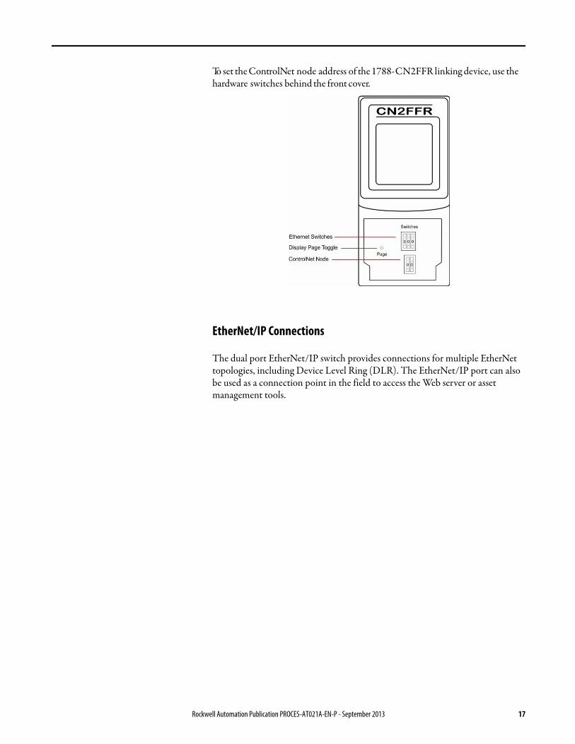
To set the ControlNet node address of the 1788-CN2FFR linking device, use the hardware switches behind the front cover.
EtherNet/IP Connections
The dual port EtherNet/IP switch provides connections for multiple EtherNet topologies, including Device Level Ring (DLR). The EtherNet/IP port can also be used as a connection point in the field to access the Web server or asset management tools.
Rockwell Automation Publication PROCES-AT021A-EN-P - September 2013 17
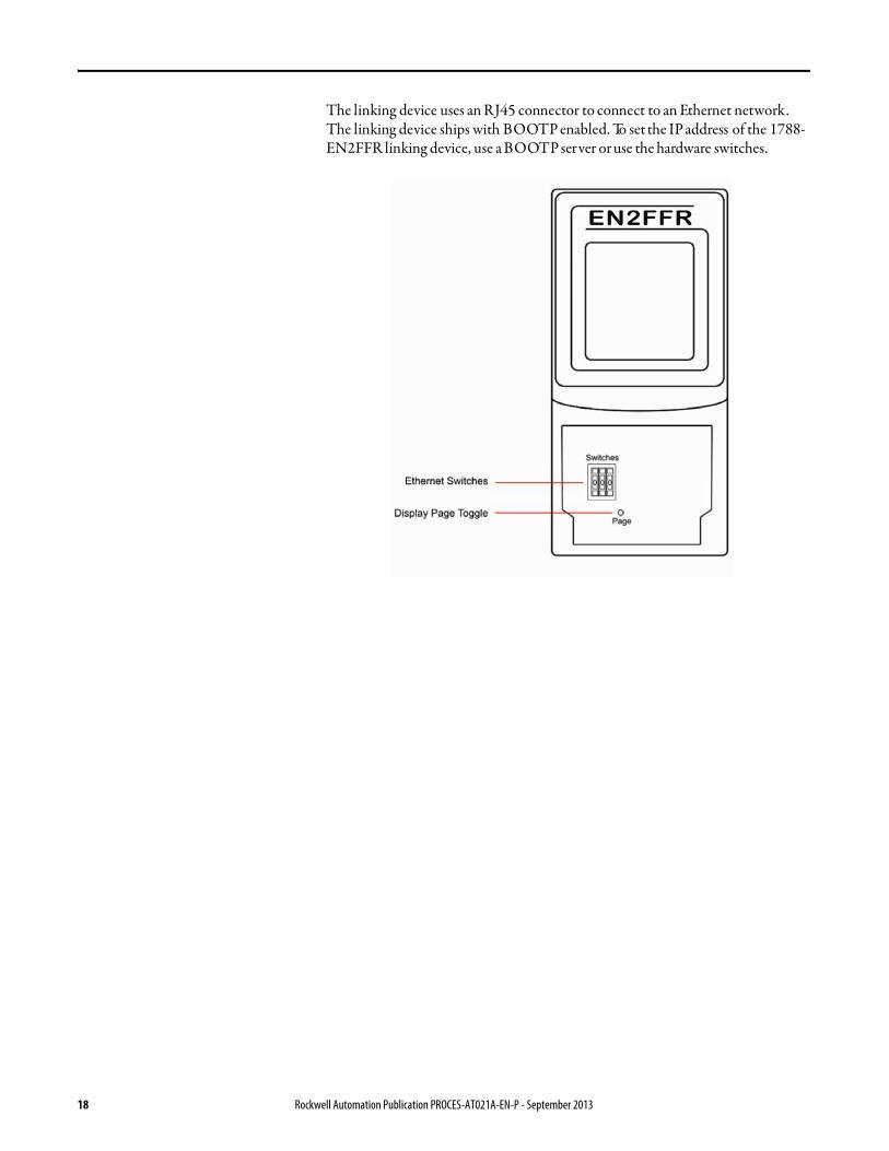
The linking device uses an RJ45 connector to connect to an Ethernet network. The linking device ships with BOOTP enabled. To set the IP address of the 1788-EN2FFR linking device, use a BOOTP server or use the hardware switches.
18 Rockwell Automation Publication PROCES-AT021A-EN-P - September 2013

Power down the linking device before changing the Ethernet switch settings. The IP address is set during power up.
Ethernet Switch Description
To set the IP address of the linking device to the 192.168.1.xxx sub net, set the switches to the required last three digits.In this example, the linking device will start up with IP address: 192.168.1.123.
To set the IP address of the linking device via a BOOTP server, set the switches to888 (factory default setting).Power up the linking device and set the IP address using any BOOTP server.Once the new IP address has been set, power down the linking device, return the switches to 000, and power up the linking device.
Normal setting after setting IP address with BOOTP.The 000 setting disables BOOTP and holds the IP address.
The linking device has the option to run the firmware that it was originally shipped with.If the power was cycled while upgrading the firmware, the linking device may not start up because the firmware was corrupted.Set the switches to 777 to set the linking device into Safe mode and upgrade the firmware again.
Rockwell Automation Publication PROCES-AT021A-EN-P - September 2013 19
Install the Add On Profile (AOP)
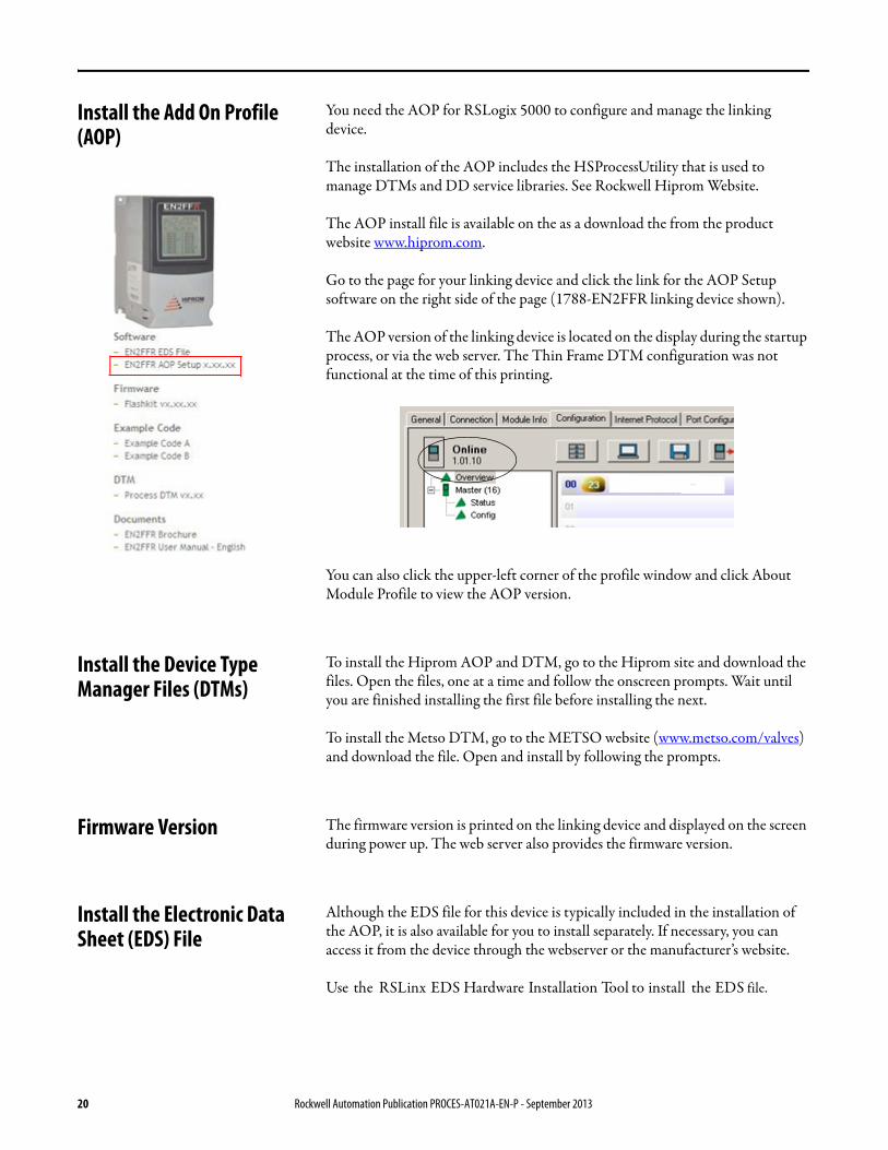
You need the AOP for RSLogix 5000 to configure and manage the linking device.
The installation of the AOP includes the HSProcessUtility that is used to manage DTMs and DD service libraries. See Rockwell Hiprom Website.
The AOP install file is available on the as a download the from the product website www.hiprom.com.
Go to the page for your linking device and click the link for the AOP Setup software on the right side of the page (1788-EN2FFR linking device shown).
The AOP version of the linking device is located on the display during the startup process, or via the web server. The Thin Frame DTM configuration was not functional at the time of this printing.
You can also click the upper-left corner of the profile window and click About Module Profile to view the AOP version.
Install the Device Type Manager Files (DTMs)
To install the Hiprom AOP and DTM, go to the Hiprom site and download the files. Open the files, one at a time and follow the onscreen prompts. Wait until you are finished installing the first file before installing the next.
To install the Metso DTM, go to the METSO website (www.metso.com/valves) and download the file. Open and install by following the prompts.
Firmware Version The firmware version is printed on the linking device and displayed on the screen during power up. The web server also provides the firmware version.
Install the Electronic Data Sheet (EDS) File
Although the EDS file for this device is typically included in the installation of the AOP, it is also available for you to install separately. If necessary, you can access it from the device through the webserver or the manufacturer’s website.
Use the RSLinx EDS Hardware Installation Tool to install the EDS file.
20 Rockwell Automation Publication PROCES-AT021A-EN-P - September 2013

Additional Information If the ND9000F is used without supply pressure, in order to make FF function blocks to operate normally, use simulation mode or supply pressure or diagnostics will be disabled.
The simulation can be enabled with the switch (DIP2) located on the circuit board, The simulation switch is OFF as the default setting. A0 block simulation is thus disabled. The simulation can be enabled with the switch (DIP2) located on the circuit board.
Figure 7 - ND9000F DIP Switches
For Profibus PA and FOUNDATION Fieldbus valves it is necessary to add some logic to the controller project. See the end of this document for details on setting up the valve positioner.
Also, When using the EN2FFR it is necessary to initialize the CAS_IN parameter. This is because the linking device operates as a pass through to the CLX therefore the normal handshaking that takes place between the cascaded function blocks is not available. This handshaking set up and logic is described at the end of this document.
Rockwell Automation Publication PROCES-AT021A-EN-P - September 2013 21

Configure via RSLogix 5000 Software
The steps necessary to setup and configure the EN2FFR and Field Device in RSLogix 5000 are presented on the following pages.
In the RSLogix 5000 project, ensure that the Ethernet Module(s) and communication is established before proceeding with installation of the EN2FFR and Field Device.
Use RSWho Active to verify the recognized devices and communications, as shown below.
The controller, bridge, and linking devices must be added to the I/O tree of the ControlLogix controller in RSLogix 5000 software before you can configure the devices.
For this example, use I/O configuration utility to select module and Add IP address for the 1756-EN2T/ENBT to 192.168.1.111 and 192.168.1.124 for the Linking Device. Your addressing may be different.
1. Open RSLogix 5000 and choose File > New.
22 Rockwell Automation Publication PROCES-AT021A-EN-P - September 2013

The New Controller window appears.
2. Enter the controller information and click OK.
The controller is now in the I/O configuration tree.
3. Right click the 1756 Backplane and choose New Module.
Rockwell Automation Publication PROCES-AT021A-EN-P - September 2013 23

4. Select the module 1756-EN2T module and click Create.
5. Enter the IP address (192.168.1.111 in this example) and any other configuration information and click OK.
24 Rockwell Automation Publication PROCES-AT021A-EN-P - September 2013

The 1756-EN2T module is now in the I/O configuration tree.
6. Right click on the EtherNet symbol and choose New Module.
7. Select the 1788-EN2FFR linking device and click create.
Rockwell Automation Publication PROCES-AT021A-EN-P - September 2013 25
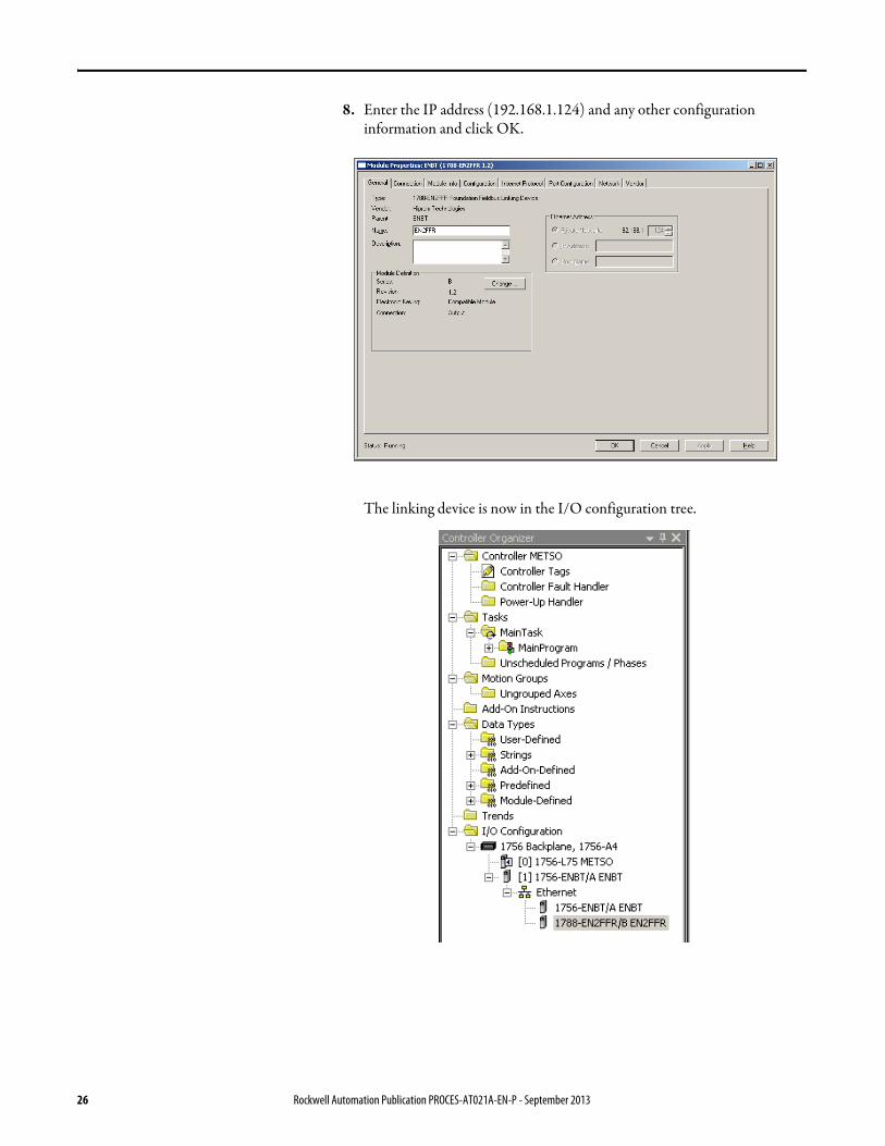
8. Enter the IP address (192.168.1.124) and any other configuration information and click OK.
The linking device is now in the I/O configuration tree.
26 Rockwell Automation Publication PROCES-AT021A-EN-P - September 2013
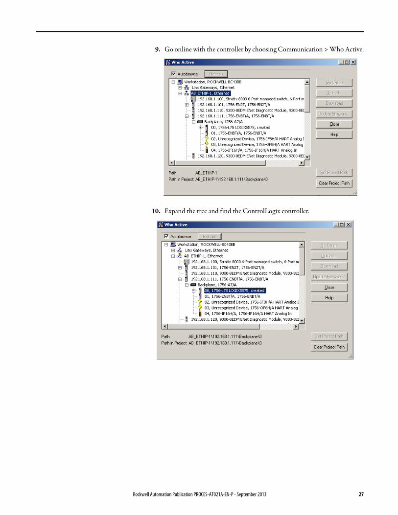
9. Go online with the controller by choosing Communication > Who Active.
10. Expand the tree and find the ControlLogix controller.
Rockwell Automation Publication PROCES-AT021A-EN-P - September 2013 27

11. Click Download.
12. Click Yes.
After the modules are added to the I/O configuration tree, you can open module properties by right-clicking the module and choosing Properties.
13. On the I/O tree, right click on the 1788-EN2FFR and choose Properties.
28 Rockwell Automation Publication PROCES-AT021A-EN-P - September 2013

14. On the Configuration tab, choose Master > Config.
15. Verify the online status in the upper left corner of the window.
Device description files are normally installed when you install the add-on profile. The following steps are only necessary if you need to download the DD (Device Description) file. If not, proceed with the next section
Rockwell Automation Publication PROCES-AT021A-EN-P - September 2013 29
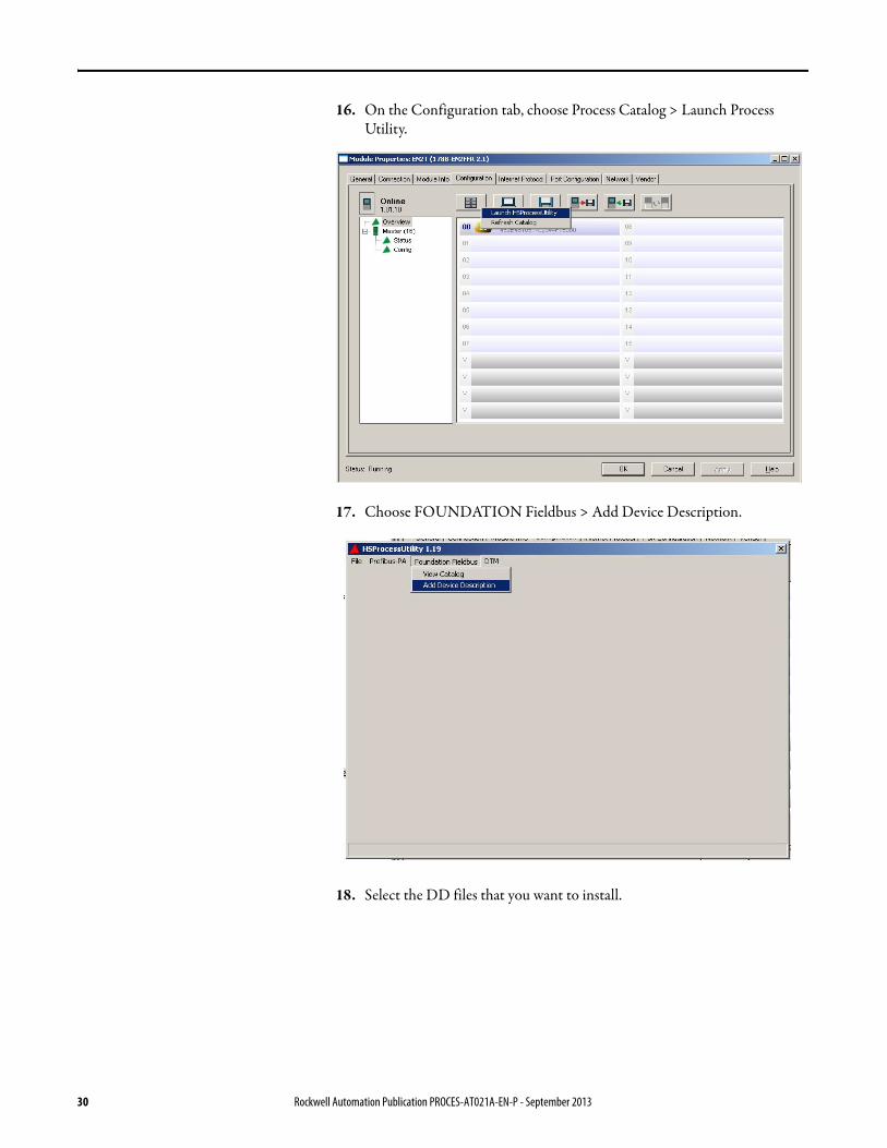
16. On the Configuration tab, choose Process Catalog > Launch Process Utility.
17. Choose FOUNDATION Fieldbus > Add Device Description.
18. Select the DD files that you want to install.
30 Rockwell Automation Publication PROCES-AT021A-EN-P - September 2013

Configure the ND9000 Valve Controller in RSLogix 5000 Software
The following steps let you configure, download, and verify available data for the field device.
It is necessary to add some logic and configure the strategy as described at the end of this document.
1. Right click on the device and choose Auto Configure Online.
2. Click the double green arrows in the left column to go online.
Rockwell Automation Publication PROCES-AT021A-EN-P - September 2013 31

3. Click Yes.
4. Click the large green arrow in the left column to download the configuration
You should see a progress bar.
32 Rockwell Automation Publication PROCES-AT021A-EN-P - September 2013

5. When the download is complete, click OK.
6. Right-click the Resource Block and choose Parameters to verify the device configuration and revision information.
Rockwell Automation Publication PROCES-AT021A-EN-P - September 2013 33
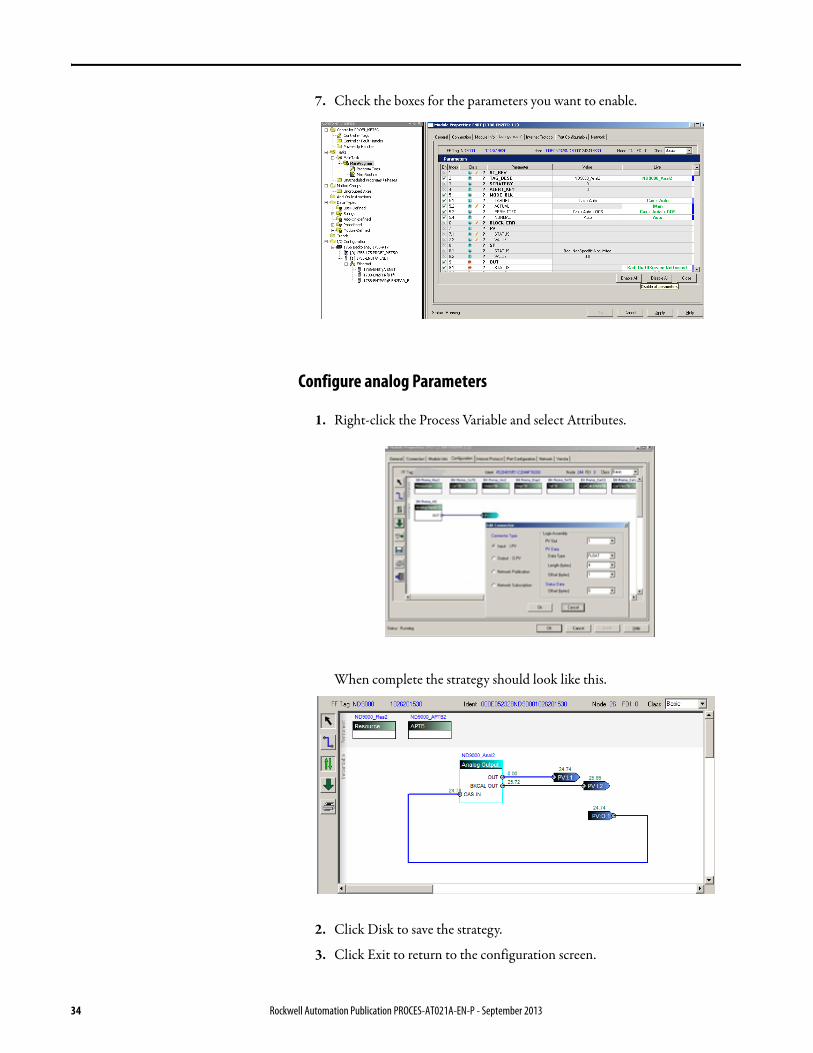
7. Check the boxes for the parameters you want to enable.
Configure analog Parameters
1. Right-click the Process Variable and select Attributes.
When complete the strategy should look like this.
2. Click Disk to save the strategy.
3. Click Exit to return to the configuration screen.
34 Rockwell Automation Publication PROCES-AT021A-EN-P - September 2013

4. Expand the device tree.
5. Click on the attributes below the device.
The screen shows the available data about the device.
6. Click OK.
Alternate Configuration Using the Thin Frame
In most cases, DTM files are included with the installation of the AOP and can be used in the Thin Frame included in RSLogix 5000 software or with a FDT Frame (such as with AssetCentre or FieldCare software). There may be an instance where the user may need to install or re-install one or more DTMs.
Rockwell Automation Publication PROCES-AT021A-EN-P - September 2013 35
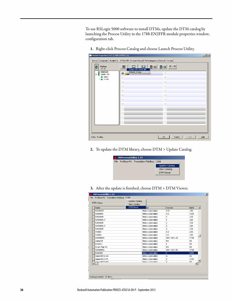
To use RSLogix 5000 software to install DTMs, update the DTM catalog by launching the Process Utility in the 1788-EN2FFR module properties window, configuration tab.
1. Right-click Process Catalog and choose Launch Process Utility.
2. To update the DTM library, choose DTM > Update Catalog.
3. After the update is finished, choose DTM > DTM Viewer.
36 Rockwell Automation Publication PROCES-AT021A-EN-P - September 2013

There might be multiple DTMs for the same device with different revisions. Select the correct revision for your device.
4. Select the DTM and click Launch DTM.
You can also choose Advance from the 1788-EN2FRR properties configuration tab.
5. To use the DTM, click Online.
Rockwell Automation Publication PROCES-AT021A-EN-P - September 2013 37

After the DTM goes online with the device, the following screen appears.
6. Save the project.
Verify Operation in RSLogix 5000 Software
Each 1788-EN2FFR consumes a total of 4 connections from the ControlLogix controller, regardless of the number of field devices. Thus the input and output image of each 1788-EN2FFR is divided into four sections A…D. The first connection has the FF Master Data.
To monitor online data, do the following.
1. Make sure the following logic has been added to the controller per the routine in appendix.
38 Rockwell Automation Publication PROCES-AT021A-EN-P - September 2013
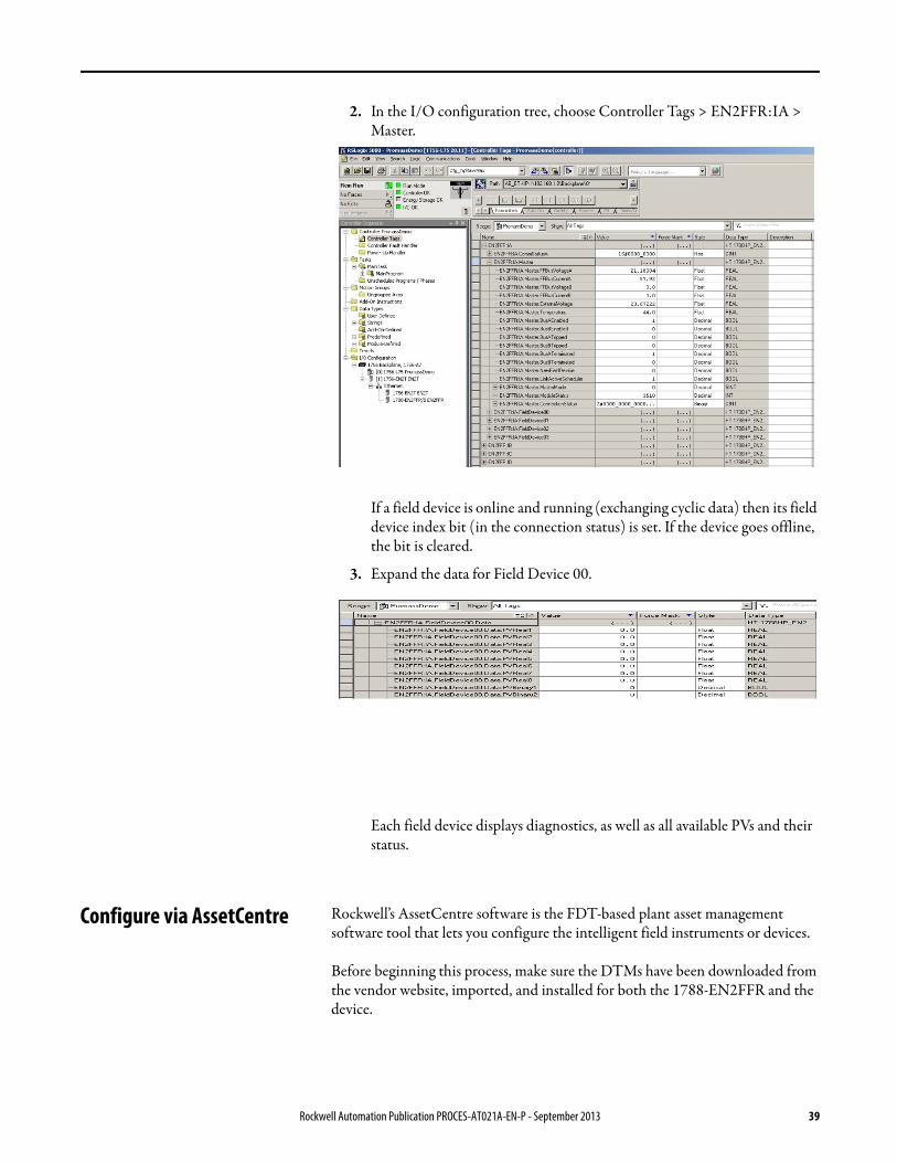
2. In the I/O configuration tree, choose Controller Tags > EN2FFR:IA > Master.
If a field device is online and running (exchanging cyclic data) then its field device index bit (in the connection status) is set. If the device goes offline, the bit is cleared.
3. Expand the data for Field Device 00.
Each field device displays diagnostics, as well as all available PVs and their status.
Configure via AssetCentre Rockwell’s AssetCentre software is the FDT-based plant asset management software tool that lets you configure the intelligent field instruments or devices.
Before beginning this process, make sure the DTMs have been downloaded from the vendor website, imported, and installed for both the 1788-EN2FFR and the device.
Rockwell Automation Publication PROCES-AT021A-EN-P - September 2013 39

1. Launch AssetCentre software and open a new project.
2. Choose Tools > DTM Catalog to update the DTM catalog.
3. Click Scan Now to verify that the DTMs you installed exist in the catalog.
4. Close the DTM catalog.
40 Rockwell Automation Publication PROCES-AT021A-EN-P - September 2013
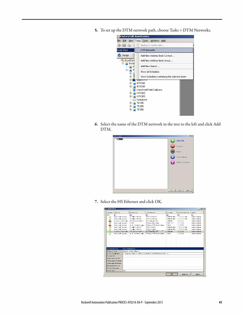
5. To set up the DTM network path, choose Tasks > DTM Networks.
6. Select the name of the DTM network in the tree to the left and click Add DTM.
7. Select the HS Ethernet and click OK.
Rockwell Automation Publication PROCES-AT021A-EN-P - September 2013 41

8. Select the HS network in the tree and click Add DTM.
9. Select the 1756- ENBT or network device DTM and click on it to view the device DTM information on the bottom of the screen.
10. Click OK.
A 1756-ENBT or other Ethernet module may not be necessary but is shown as an example.
42 Rockwell Automation Publication PROCES-AT021A-EN-P - September 2013

11. Enter the IP Address (111 for this example) and Scan rate.
12. Click Enter to accept the entries.
13. Click Next.
14. Select the next network device and click Add DTM.
Rockwell Automation Publication PROCES-AT021A-EN-P - September 2013 43
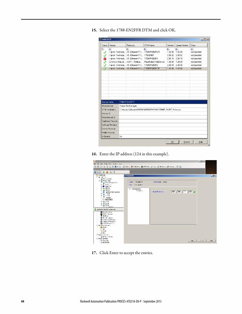
15. Select the 1788-EN2FFR DTM and click OK.
16. Enter the IP address (124 in this example).
17. Click Enter to accept the entries.
44 Rockwell Automation Publication PROCES-AT021A-EN-P - September 2013
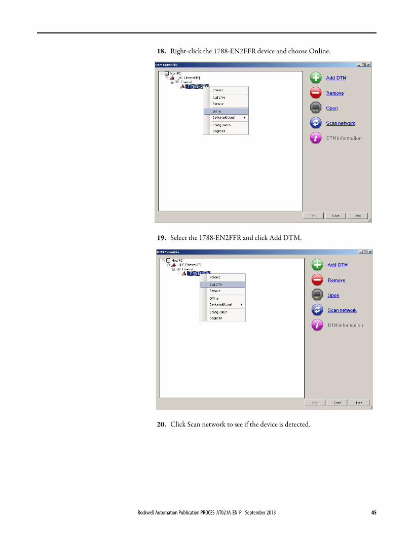
18. Right-click the 1788-EN2FFR device and choose Online.
19. Select the 1788-EN2FFR and click Add DTM.
20. Click Scan network to see if the device is detected.
Rockwell Automation Publication PROCES-AT021A-EN-P - September 2013 45

21. Select the correct DTM and click OK.
22. Enter the node address (24 in this example).
23. Click Enter to accept the address.
24. Click Next.
46 Rockwell Automation Publication PROCES-AT021A-EN-P - September 2013

25. Right-click the devices in the tree to verify online status.
26. Select the Device and click Open.
27. Verify the device is connected by looking at the bottom left corner of the screen.
28. Click Next.
Use the tree on the left of the DTM frame to navigate to different properties of the device, make changes, or view data.
Rockwell Automation Publication PROCES-AT021A-EN-P - September 2013 47
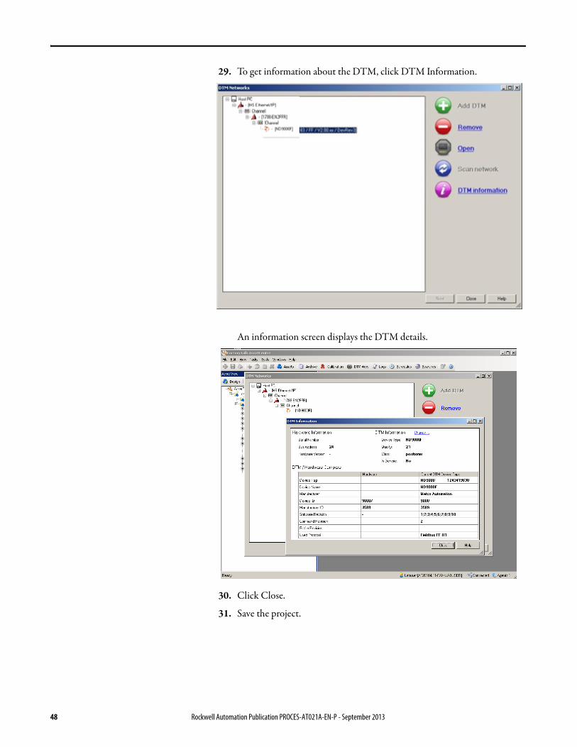
29. To get information about the DTM, click DTM Information.
An information screen displays the DTM details.
30. Click Close.
31. Save the project.
48 Rockwell Automation Publication PROCES-AT021A-EN-P - September 2013

Verify DTM Installation and Operation.
1. Click Design to enter design mode.
2. Choose Process Area > New.
3. From the Process Area Tree in the Asset Type to Add window, click Instrument and then click OK.
Rockwell Automation Publication PROCES-AT021A-EN-P - September 2013 49

4. Enter a device name (Metso in this example) and click OK.
5. Right-click the newly-named device and choose Properties.
50 Rockwell Automation Publication PROCES-AT021A-EN-P - September 2013

6. Choose DTM Addressing Info and click the Grey Box (…) on the right side of the screen.
7. Select the device and click OK.
Rockwell Automation Publication PROCES-AT021A-EN-P - September 2013 51

8. Click OK.
9. Right-click the instrument and choose DTM View.
52 Rockwell Automation Publication PROCES-AT021A-EN-P - September 2013
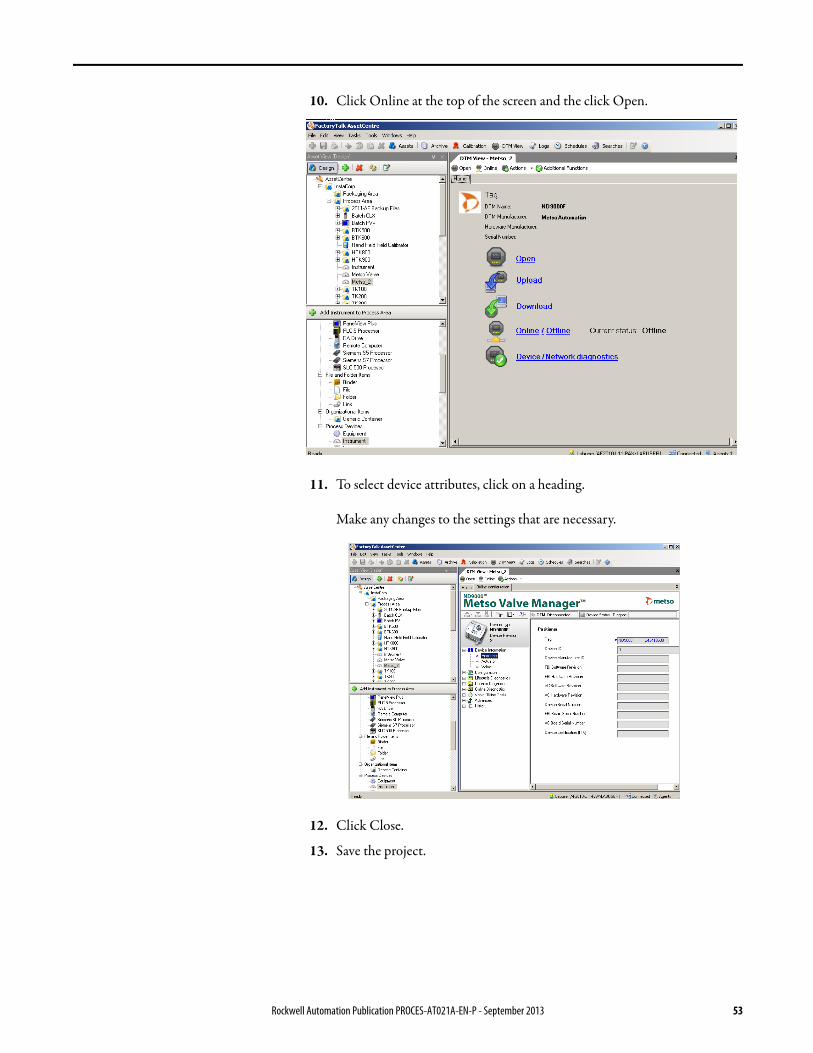
10. Click Online at the top of the screen and the click Open.
11. To select device attributes, click on a heading.
Make any changes to the settings that are necessary.
12. Click Close.
13. Save the project.
Rockwell Automation Publication PROCES-AT021A-EN-P - September 2013 53

Initialization of CAS_IN Parameter with the 1788-EN2FFR/CN2FFR Linking Device
This initialization of the CAS_IN parameter is based on the following strategy.
The linking device operates as a pass through to the ControlLogix platform, so the normal handshaking that takes place between cascaded function blocks is not available. Use the CAS_IN parameters to provide this handshaking in the ladder program of the processor.
The initialization process must account for two conditions:• The Not Invited status that results after a download or mode change in the
processor.• The Initialize Request that results from a mode change in the function
block.
There maybe other conditions that must be accounted for depending on the application.
54 Rockwell Automation Publication PROCES-AT021A-EN-P - September 2013

Manual Initialization
Manual initialization of the analog output function block.• The status and values that are returned from the analog output function
block BKCAL_OUT parameter are passed to the ControlLogix data table through the PV:I:2 connector.
• The status and values (SP) are sent to the AO FB CAS_IN parameter through the PV:O:1 connector.
1. Check the permitted states of the MODE parameter.
Rockwell Automation Publication PROCES-AT021A-EN-P - September 2013 55

2. Add CAS mode must to the PERMITTED parameters.
3. Click OK.
4. Set the MODE TARGET to Cas/Auto.
56 Rockwell Automation Publication PROCES-AT021A-EN-P - September 2013

The MODE will not go to Cas/Auto is because the CAS_IN parameter shows Bad status and the BKCAL_IN parameter shows the error NotInvited.
The NotInvited status occurs because the CAS_IN parameter has not been set to CAS mode so that initialization can take place.
5. Set the value to 1 for GoodCascade and NotLimited.
Rockwell Automation Publication PROCES-AT021A-EN-P - September 2013 57
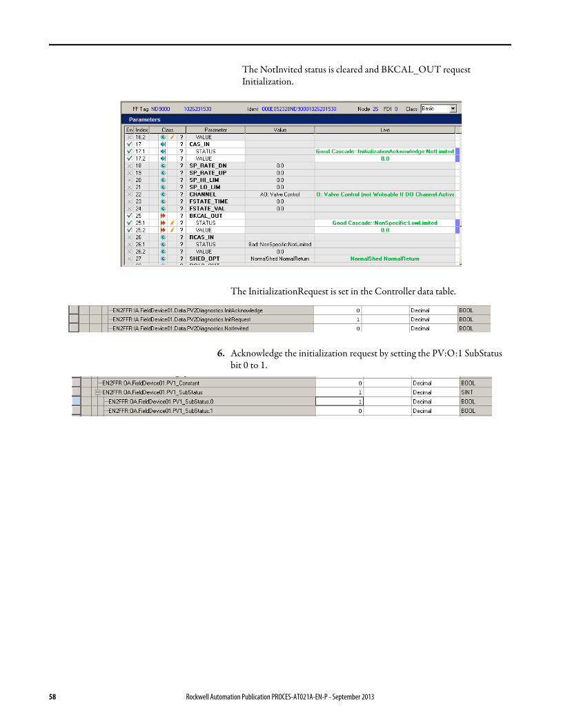
The NotInvited status is cleared and BKCAL_OUT request Initialization.
The InitializationRequest is set in the Controller data table.
6. Acknowledge the initialization request by setting the PV:O:1 SubStatus bit 0 to 1.
58 Rockwell Automation Publication PROCES-AT021A-EN-P - September 2013
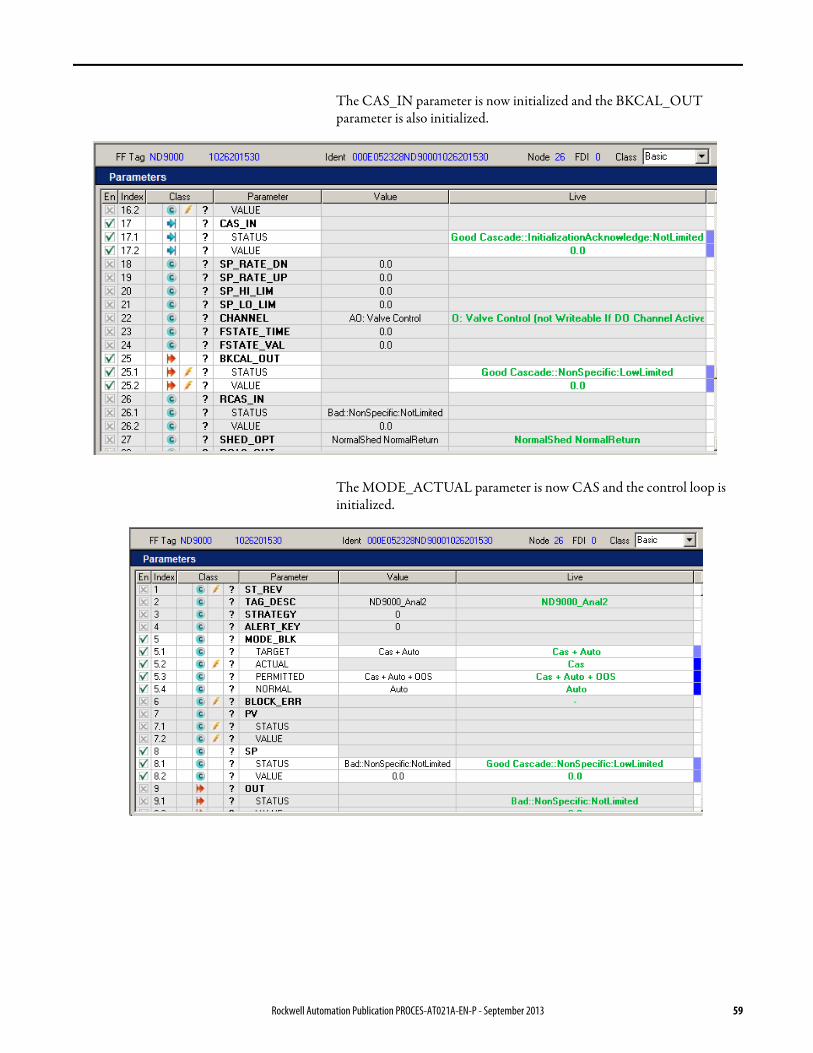
The CAS_IN parameter is now initialized and the BKCAL_OUT parameter is also initialized.
The MODE_ACTUAL parameter is now CAS and the control loop is initialized.
Rockwell Automation Publication PROCES-AT021A-EN-P - September 2013 59

7. To verify that the control loop is initialized, change the value of the PV:O:1 and observe whether the SP parameter value changes.
Programmatic Initialization
1. Verify that BKCAL_OUT is reporting cascade mode
IFEN2FFR:IA.FieldDevice01.Data.PV2_GoodCascade =1 ANDEN2FFR:IA.FieldDevice01.Data.PV2_NotLimited = 1THEN
2. Test NotInvited condition
IF EN2FFR:IA.FieldDevice01.Data.PV2Diagnostics.NotInvited = 1THENSet EN2FFR:OA.FieldDevice01.PV1_GoodCascade = 1Set EN2FFR:OA.FieldDevice01.PV1_NotLimited = 1
60 Rockwell Automation Publication PROCES-AT021A-EN-P - September 2013

3. Verify NotInvited condition cleared and IniTRequest
IF EN2FFR:IA.FieldDevice01.Data.PV2Diagnostics.NotInvited = 0ANDEN2FFR:IA.FieldDevice01.Data.PV2Diagnostics.InitRequest = 1THENSet EN2FFR:OA.FieldDevice01.PV1_SubStatus.0 = 1
4. Verify Initialized state.
IF EN2FFR:IA.FieldDevice01.Data.PV2Diagnostics.GoodCasade_NonSpecific = 1THENSet EN2FFR:OA.FieldDevice01.PV1_SubStatus.0 = 0END
Rockwell Automation Publication PROCES-AT021A-EN-P - September 2013 61

Publication PROCES-AT021A-EN-P - September 2013
Rockwell Automation Support
Rockwell Automation provides technical information on the Web to assist you in using its products. At http://www.rockwellautomation.com/support, you can find technical manuals, technical and application notes, sample code and links to software service packs, and a MySupport feature that you can customize to make the best use of these tools. You can also visit our Knowledgebase at http://www.rockwellautomation.com/knowledgebase for FAQs, technical information, support chat and forums, software updates, and to sign up for product notification updates.
For an additional level of technical phone support for installation, configuration, and troubleshooting, we offer TechConnectSM support programs. For more information, contact your local distributor or Rockwell Automation representative, or visit http://www.rockwellautomation.com/support/.
Installation Assistance
If you experience a problem within the first 24 hours of installation, review the information that is contained in this manual. You can contact Customer Support for initial help in getting your product up and running.
New Product Satisfaction Return
Rockwell Automation tests all of its products to help ensure that they are fully operational when shipped from the manufacturing facility. However, if your product is not functioning and needs to be returned, follow these procedures.
Documentation Feedback
Your comments will help us serve your documentation needs better. If you have any suggestions on how to improve this document, complete this form, publication RA-DU002, available at http://www.rockwellautomation.com/literature/.
United States or Canada 1.440.646.3434
Outside United States or Canada Use the Worldwide Locator at http://www.rockwellautomation.com/rockwellautomation/support/overview.page, or contact your local Rockwell Automation representative.
United States Contact your distributor. You must provide a Customer Support case number (call the phone number above to obtain one) to your distributor to complete the return process.
Outside United States Please contact your local Rockwell Automation representative for the return procedure.
Rockwell Otomasyon Ticaret A.Ş., Kar Plaza İş Merkezi E Blok Kat:6 34752 İçerenköy, İstanbul, Tel: +90 (216) 5698400
Copyright © 2013 Rockwell Automation, Inc. All rights reserved. Printed in the U.S.A.