metso neles nd9000 valve controller via hart to the...
TRANSCRIPT

METSO Neles ND9000 Valve Controller via HART to the PlantPAx Process Automation System
Application Technique

Important User Information Solid-state equipment has operational characteristics differing from those of electromechanical equipment. Safety Guidelines for the Application, Installation and Maintenance of Solid State Controls (publication SGI-1.1 available from your local Rockwell Automation sales office or online at http://www.rockwellautomation.com/literature/) describes some important differences between solid-state equipment and hard-wired electromechanical devices. Because of this difference, and also because of the wide variety of uses for solid-state equipment, all persons responsible for applying this equipment must satisfy themselves that each intended application of this equipment is acceptable.
In no event will Rockwell Automation, Inc. be responsible or liable for indirect or consequential damages resulting from the use or application of this equipment.
The examples and diagrams in this manual are included solely for illustrative purposes. Because of the many variables and requirements associated with any particular installation, Rockwell Automation, Inc. cannot assume responsibility or liability for actual use based on the examples and diagrams.
No patent liability is assumed by Rockwell Automation, Inc. with respect to use of information, circuits, equipment, or software described in this manual.
Reproduction of the contents of this manual, in whole or in part, without written permission of Rockwell Automation, Inc., is prohibited.
Throughout this manual, when necessary, we use notes to make you aware of safety considerations.
Allen-Bradley, Rockwell Software, Rockwell Automation, and TechConnect are trademarks of Rockwell Automation, Inc.
Trademarks not belonging to Rockwell Automation are property of their respective companies.
WARNING: Identifies information about practices or circumstances that can cause an explosion in a hazardous environment, which may lead to personal injury or death, property damage, or economic loss.
ATTENTION: Identifies information about practices or circumstances that can lead to personal injury or death, property damage, or economic loss. Attentions help you identify a hazard, avoid a hazard, and recognize the consequence.
SHOCK HAZARD: Labels may be on or inside the equipment, for example, a drive or motor, to alert people that dangerous voltage may be present.
BURN HAZARD: Labels may be on or inside the equipment, for example, a drive or motor, to alert people that surfaces may reach dangerous temperatures.
IMPORTANT Identifies information that is critical for successful application and understanding of the product.
8 Rockwell Automation Publication PROCES-AT020A-EN-P - September 2013

Introduction The purpose of this document is to provide a simple proven step by step guide to integrating and configuring the Metso Neles Valve controller into the Rockwell Automation PlantPAx process Automation System using the 3 process networks. These include HART, FOUNDATION Fieldbus and Profibus PA. This document is intended to provide a tested method to quickly connect to and communicate with the field device. I t is not meant to show all of the methods nor is it intended to be a detailed document pertaining to all of the features, capabilities and application of the field devices.
To supply robust system solutions, Rockwell Automation pre-tests many third-party manufactured HART, FOUNDATION Fieldbus, and PROFIBUS PA field devices in the system test laboratory for compatibility with the Rockwell Automation PlantPAx process automation system. Each field device is connected to the PlantPAx system and is subjected to interoperability testing procedures similar to operating procedures in your plant. The results of each field test are recorded in a test report for integration planning purposes.
For this field device, an additional step provides an “Integration Document” and “Interoperability Statement” for each tested instrument. The Integration Document provides information on installation, configuration, startup, and operation of the integrated system. The Interoperability Statement is assurance that the field device meets PlantPAx system interoperability performance measures, as established by Rockwell Automation . Both the Integration Document and Interoperability Statement help reduce risk with ease of integration.
The overall purpose of this document is to provide you with proven solutions that combine field instrumentation with fieldbus networks, such as HART, FOUNDATION Fieldbus, and PROFIBUS PA networks, with asset management capabilities and Rockwell Automation’s system capabilities to provide a total engineered solution.
Through pre-engineered integration in support of increasing requirements for plant-wide control, the document offers the following benefits:
• Reduced integration costs throughout engineering, commissioning, and start-up
• Optimized plant availability and output• Ensured product quality and consistency• Optimized traceability to meet regulatory demands• Predictive maintenance through intelligent instruments
Rockwell Automation Publication PROCES-AT020A-EN-P - September 2013 9

For new construction, process improvements at an existing plant, or operating cost reductions, the benefits are:
• Reduces risk, reduces integration costs, and protects investment with pre-engineered interoperability. Both companies believe open systems and standardized interfaces bring maximum benefits.
• Advanced diagnostics with plant-wide control provides better visibility of plant health and easier access to instrument diagnostics, which ultimately leads to faster troubleshooting and improves decision-making.
• Collaborative lifecycle management leads to improvements in design, engineering, and startup and support of plants. This collaboration increases productivity, manages information about instrumentation assets, optimizes plant assets, and results in a complete lifecycle management solution.
Application Overview This document provides a step-by-step approach to integrating a Metso Neles valve controller using HART into the PlantPAx Automation System.
The ControlLogix platform provides a full range of input and output modules to span a wide variety of applications. The ControlLogix architecture uses producer/consumer technology, allowing input information and output status to be shared by all ControlLogix controllers in the system.
This integration document assumes you have a working knowledge of ControlLogix systems.
Section Describes
Application overview Details about the field device and control system
Example system Specifications on the required hardware and software components
Installation How to install and connect the field device, linking device and other components
Configuration How to:• Configure the HART I/O• Configure the measurement instrument
Visualization How to implement and configure a graphical display of device information
10 Rockwell Automation Publication PROCES-AT020A-EN-P - September 2013
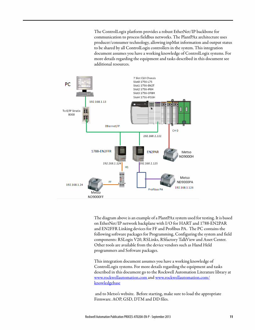
The ControlLogix platform provides a robust EtherNet/IP backbone for communication to process fieldbus networks. The PlantPAx architecture uses producer/consumer technology, allowing inpMut information and output status to be shared by all ControlLogix controllers in the system. This integration document assumes you have a working knowledge of ControlLogix systems. For more details regarding the equipment and tasks described in this document see additional resources.
The diagram above is an example of a PlantPAx system used for testing. It is based on EtherNet/IP network backplane with I/O for HART and 1788-EN2PAR and EN2FFR Linking devices for FF and Profibus PA. The PC contains the following software packages for Programming, Configuring the system and field components: RSLogix V20, RSLinks, RSfactory TalkView and Asset Center. Other tools are available from the device vendors such as Hand Held programmers and Software packages.
This integration document assumes you have a working knowledge of ControlLogix systems. For more details regarding the equipment and tasks described in this document go to the Rockwell Automation Literature library at www.rockwellautomation.com and www.rockwellautomation.com/knowledgebase
and to Metso’s website. Before starting, make sure to load the appropriate Firmware. AOP, GSD, DTM and DD files.
Rockwell Automation Publication PROCES-AT020A-EN-P - September 2013 11

The AOP can be downloaded from Rockwell Hiprom at www.hiprom.com.
Device files can be downloaded from www.metso.com/valves.
Device Information Intelligent Valve Controller, Series ND9000
Neles ND9000 is a top class intelligent valve controller designed to operate on any valve and actuator type in all industry areas. With unique performance features, it ensures maximum control accuracy in all operating conditions. The diagnostic capabilities provide the user with valuable information as a basis for predictive maintenance. For more details see ND9000 Installation, Maintenance and operators Instructions (7ND9071en.pdf ) (www.metsoautomation.com/ND9000).
• Enclosure options– ND9100: Anodized aluminum alloy and polymer composite– ND9200: Anodized aluminum alloy and tempered glass– ND9300: Full 316 stainless steel– Communication options– ND9000H HART– ND9000F, – FOUNDATION Fieldbus H1– ND9000P Profibus PA
• Wide coverage of hazardous area approvals (Explosion/Flame proof, Intrinsically safe) – ATEX, IECEx, cCSAus, Inmetro, GOST R
• Single device for double and single-acting actuators, as well as linear and rotary valves
• Simple and fast commissioning (only 4 parameters needed: signal, rotating direction, actuator type, fail safe action)
• 3 types of spool valves for different actuator sizes– Small actuators < 1 dm3 = 2 mm spool valve ≥ 5 Nm3/h / 3 scfm– Medium actuators 1 dm3 - 3 dm3 = 3 mm spool valve ≥ 12 Nm3/h / 7
scfm– Large actuators > 3 dm3 = 6 mm spool valve ≥ 38 Nm3/h / 22 scfm
• The adaptive control algorithm together with the intelligent nozzle / flapper system ensures best control results even under changing process and environmental conditions.– Dead band ≤ 0.1% / hysteresis < 0.5% (according to IEC61514
measured with a diaphragm actuator at moderate constant-load in ambient temperature).
• By continuous monitoring of the supply and actuator pressure– leaks in the control system can be identified and compensated– best control results will be achieved even with external instrumentation
components (volume booster)
12 Rockwell Automation Publication PROCES-AT020A-EN-P - September 2013

• Valve specific functions (dead angle, cut-offs and valve characterization) integrated.
• Local user interface enables easy usage of the device– Parameterization and calibration– Measurements: input signal, valve position, temperature, supply
pressure, actuator pressure difference– All warnings, alarm messages as clear text messages in English, German,
French• Extremely high vibration resistance• Continuous self-monitoring, as well as online, counter and lifecycle
diagnosis enables– rapid detection of faulty components– accurate assessment of the specific valve performance – statement about negative process and environmental influences– assessment of the performance of the superior controller
• All diagnostic data are stored in the device over the entire operating period (up to 25 years)
• The event log stores up to 8000 events (alerts, alarms, notes)• Performance view• Supports FDT/DTM technology• Advanced Offline-Tests according IEC61514 / ISA 75.25-2000
– Multipoint step response test– Hysteresis test– Valve analysis test– Dead band test
The Performance View of the Metso Valve Manager graphically displays indexes of the valve, actuator and positioner, as well as indexes of control performance and the application environment. Report will show explanations of the status of each component and guidelines for recommended actions.
Rockwell Automation Publication PROCES-AT020A-EN-P - September 2013 13

Figure 1 - Performance View
Figure 2 - Example Diagnostics Trend
14 Rockwell Automation Publication PROCES-AT020A-EN-P - September 2013

Figure 3 - Multipoint Step Response Test
Control System The control system includes these components:
Hardware Components
For further details, see the PlantPAx Process Automation System Selection Guide, publication PROCES-SG001.
Component Description
Controller The ControlLogix controller is a modular, high performance control that uses RSLogix 5000 programming software to configure, program, and monitor a system.
HART interface The PlantPAx system has a number of HART interface I/O options including the 1756- OF8H, Flex 1794, Compact, 1769 and point 1734 options. For this configuration the 1756-OF8H was used though any of the above HART options mentioned above are feasible.
Programming software PlantPAx is an easy object-oriented, explorer-based, drag-and-drop configuration that allows you to build complex process functions. Furthermore, the software allows you to mix and match IEC61131-3 compliant programming languages. All supported programming languages share the same development environment, tag database, and user interface, resulting in reduced training and higher productivity.
Visualization software FactoryTalk® View Site Edition software is HMI software program for monitoring, controlling, and acquiring data from manufacturing operations throughout an enterprise. A generic display provides a graphical representation via faceplates of the field instrument.
Component Description
Metso Neles valve controllers ND9000H
1756-OF8H I/O module HART output module
Allen-Bradley EtherNet/IP Bridge 1756-L75 ControlLogix controller with a 1756-EN2T module
Rockwell Automation Publication PROCES-AT020A-EN-P - September 2013 15

Software Components
For specifications of the engineering workstation (EWS) and operator workstation (OWS), see the Integrated Architecture for Process Control System Recommendations Reference Manual, publication PROCES-RM001.
Installation and Wiring The following sections provide instructions on how to connect the HART (ND9000H) valve controller to a DCS system.
Connect a ND9000H HART Valve Controller
The ND9000H is powered by a standard 4–20 mA current loop that also functions as a carrier to the HART communication.
The input signal cable is led through a• M20 x 1.5 cable gland, or• 1/2 NPT cable gland
Connect the conductors to the terminal strip as shown below. It is recommended that the earthing of the input cable shield be carried out from the DCS end only. The position transmitter is connected to 2-pole terminal PT as shown below. The position transmitter needs an external power supply.
Component Catalog Number
RSLogix 5000 Enterprise Series programming software, Professional editionIncludes:• RSLinx Classic software• RSLinx Enterprise software
9324-RLD700NXENE
FactoryTalk View Site Edition (SE) software (optional) 9701-VWSXXXXXENE
FactoryTalk AssetCentre server 9515-ASTSRVRENE
FactoryTalk AssetCentre process device configuration 9515-ASTPRDCFENE
FieldCare Standard Asset Management software (optional)
—
16 Rockwell Automation Publication PROCES-AT020A-EN-P - September 2013

Figure 4 - ND9000H Terminals
Connect a ND9000F Foundation FIELDBUS and a ND9000P Profibus PA Valve Controllers
The ND9000F is powered by FOUNDATION fieldbus (IEC 61158-2). The ND9000P is powered by Profibus PA (IEC 61158-2). The same bus cable is used also for the fieldbus communication. The bus cable is led through a
• M20 x 1.5 cable gland, or• 1/2 NPT cable gland
Connect the conductors to the terminal strip as shown in below.
Rockwell Automation Publication PROCES-AT020A-EN-P - September 2013 17

Figure 5 - ND9000F and ND9000P Terminals
If ND9000F is used without supply pressure to make FF function blocks to operate normally shall simulation mode used or supply pressure diagnostics shall be disabled.
Assembly Related Parameter Settings
The configuration parameters shall be defined based on valve assembly. Parameters can be set via device DTM or via LUI (local user interface). For details see ND9000 Installation, Maintenance and operators Instructions (7ND9071en.pdf ) (www.metsoautomation.com/ND9000).
Fieldbus Connector
The connection technology of FOUNDATION Fieldbus allows measuring devices to be connected to the fieldbus via uniform mechanical connections, such as T-boxes, distribution modules, etc. This connection technology, which uses prefabricated distribution modules and plug-in connectors, offers substantial advantages over conventional wiring.
• Field devices can be removed, replaced or added at any time during normal operation. Communication is not interrupted.
• Installation and maintenance are significantly easier.• Existing cable infrastructures can be used and expanded instantly, e.g.
when constructing new star distributors using 4-channel or 8-channel distribution modules.
18 Rockwell Automation Publication PROCES-AT020A-EN-P - September 2013

Connect a 2-wire Field Instrument to the HART Input Module
HART communication is active only with current inputs. Connect a 2-wire field instrument to any channel of the 1756- output module in a 2-wire configuration for current input. This figure shows a 2-wire field instrument connected to channel 4. For the example we used channel 0.
Figure 6 - 1756-OF8H Wiring Diagram
Voltage outputs use the terminal block pins VOUT and RTN. Current outputs use the terminal block pins IOUT and RTN.
Rockwell Automation Publication PROCES-AT020A-EN-P - September 2013 19

Connect a HART Handheld Device (optional)
Connect the Field Xpert device by one of these methods:• • Connection across load resistor.
• Connection across RN221N (Ex version).
Turn power on to both the handheld device and the modem to establish the Bluetooth connection.
20 Rockwell Automation Publication PROCES-AT020A-EN-P - September 2013

Configure the HART Module via RSLogix 5000 Software
1. Use the RSWHO Active utility to verify the active devices as shown below.
2. In RSLogix 5000 software, create a new project.
3. In the I/O Configuration tree, right click, New Module.
4. Select the controller and enter the configuration information.
5. Click OK.
Rockwell Automation Publication PROCES-AT020A-EN-P - September 2013 21

6. Right-click the controller backplane and choose New Module.
7. Select the 1756-OF8H module.
22 Rockwell Automation Publication PROCES-AT020A-EN-P - September 2013
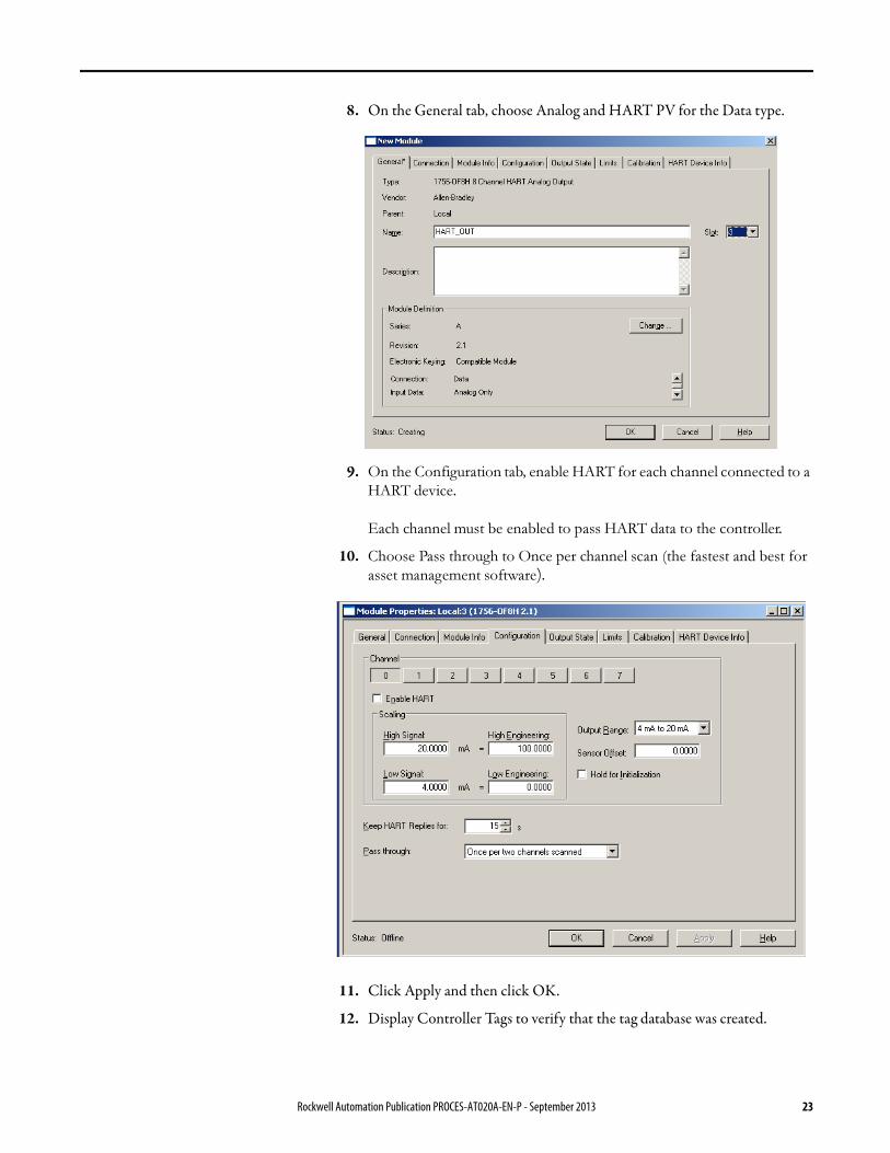
8. On the General tab, choose Analog and HART PV for the Data type.
9. On the Configuration tab, enable HART for each channel connected to a
HART device.
Each channel must be enabled to pass HART data to the controller.
10. Choose Pass through to Once per channel scan (the fastest and best for
asset management software).
11. Click Apply and then click OK.
12. Display Controller Tags to verify that the tag database was created.
Rockwell Automation Publication PROCES-AT020A-EN-P - September 2013 23
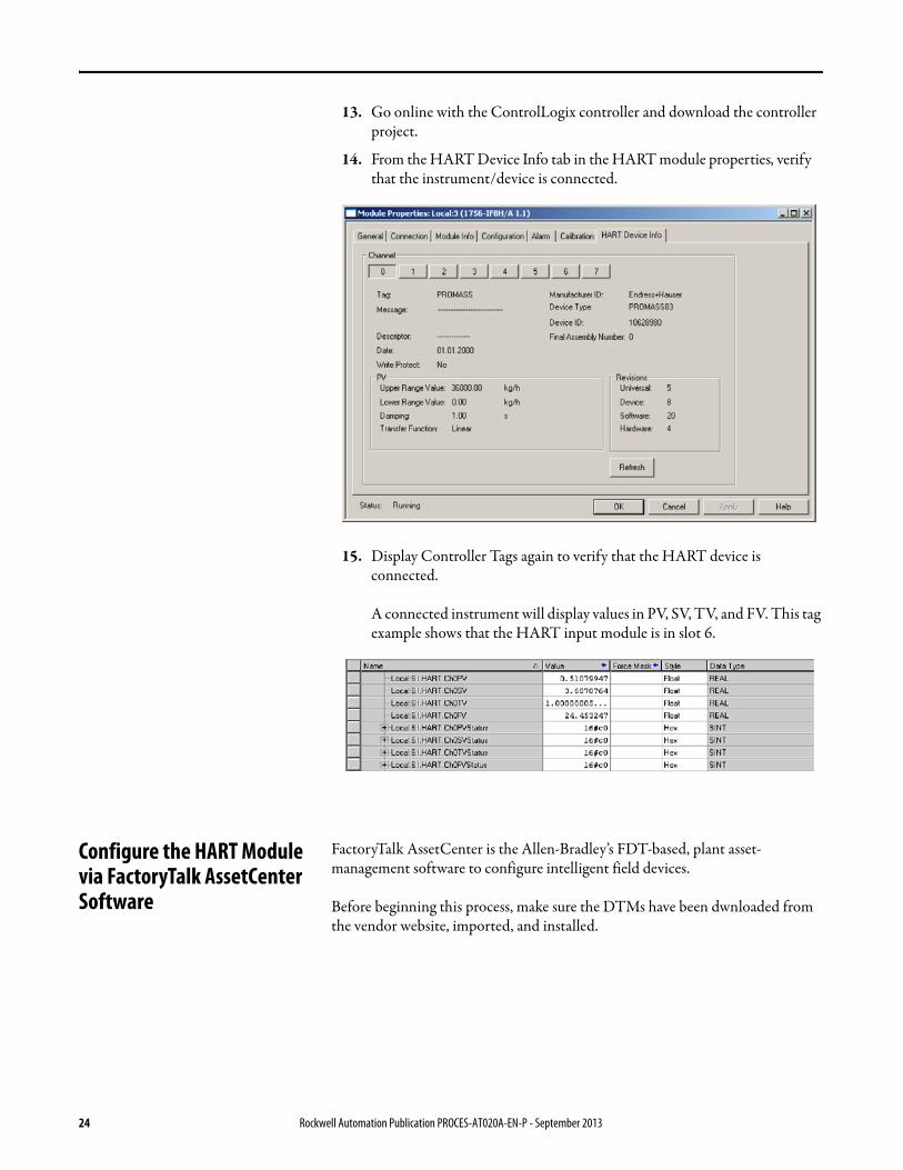
13. Go online with the ControlLogix controller and download the controller project.
14. From the HART Device Info tab in the HART module properties, verify that the instrument/device is connected.
15. Display Controller Tags again to verify that the HART device is connected.
A connected instrument will display values in PV, SV, TV, and FV. This tag example shows that the HART input module is in slot 6.
Configure the HART Module via FactoryTalk AssetCenter Software
FactoryTalk AssetCenter is the Allen-Bradley’s FDT-based, plant asset-management software to configure intelligent field devices.
Before beginning this process, make sure the DTMs have been dwnloaded from the vendor website, imported, and installed.
24 Rockwell Automation Publication PROCES-AT020A-EN-P - September 2013

1. After installing the appropriate DTM files, start AssetCenter software and open a new project.
2. To update the DTM catalog, choose Tools > DTM Catalog.
3. To verify that the DTMs are installed, click Scan Now.
4. Close the DTM catalog.
Rockwell Automation Publication PROCES-AT020A-EN-P - September 2013 25

5. To configure the DTM network paths, choose Tasks > DTM Networks.
6. Select the name of the DTM network on the tree to the left and then click Add DTM.
26 Rockwell Automation Publication PROCES-AT020A-EN-P - September 2013

7. Select the chassis and click OK.
The tree looks like this.
8. Select the chassis and click Add DTM.
Rockwell Automation Publication PROCES-AT020A-EN-P - September 2013 27

9. Select the module and click OK.
The module should now be added to the tree.
10. Select the module and click Add DTM.
11. Enter the slot number and other configuration data.
28 Rockwell Automation Publication PROCES-AT020A-EN-P - September 2013

12. Press Enter to accept the data.
Rockwell Automation Publication PROCES-AT020A-EN-P - September 2013 29

The tree should look like this.
13. Select the module and click Add DTM.
14. Choose the correct channel and click OK.
30 Rockwell Automation Publication PROCES-AT020A-EN-P - September 2013

15. Choose the appropriate device and revision and click OK.
Use the native DTM even though the example shows the iDTM.
The tree should look like this.
Rockwell Automation Publication PROCES-AT020A-EN-P - September 2013 31

16. CLick DTM Information.
17. Click Design.
18. Choose Process Area > New.
32 Rockwell Automation Publication PROCES-AT020A-EN-P - September 2013

19. Choose the instrument.
20. Enter the name of the device.
In this example, the name is Metso9000Hart_3.
21. Click OK.
Rockwell Automation Publication PROCES-AT020A-EN-P - September 2013 33

22. Right-click on the name of the device and choose Properties.
23. Click DTM Addressing Info.
24. Click the key on the right hand side of the screen.
34 Rockwell Automation Publication PROCES-AT020A-EN-P - September 2013

25. Select the device.
26. Click OK
27. Click OK.
Rockwell Automation Publication PROCES-AT020A-EN-P - September 2013 35

28. Select the device and ch oose DTM View.
36 Rockwell Automation Publication PROCES-AT020A-EN-P - September 2013
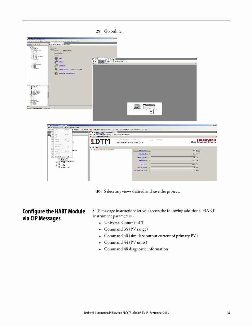
29. Go online.
30. Select any views desired and save the project.
Configure the HART Module via CIP Messages
CIP message instructions let you access the following additional HART instrument parameters:
• Universal Command 3• Command 35 (PV range)• Command 40 (simulate output current of primary PV)• Command 44 (PV units)• Command 48 diagnostic information
Rockwell Automation Publication PROCES-AT020A-EN-P - September 2013 37

Diagnostic Messages: Command 48 provides information about an instrument when an instrument's transmitter or sensor is not running properly. Command 48 produces a byte and bit based output that can be translated into specific error codes that can help maintenance personnel determine more specific details about abnormal conditions with HART instruments.
Performance Considerations Keep in mind these considerations when integrating HART instruments:• The HART communication protocol has a relatively slow baud rate at
1200/2400 bits per second.• The 1756-IF8H HART module executes one HART command per
instrument at a time. Analog (4-20ma) data are delivered from all channels simultaneously.
• The time of execution for Universal Command 3 is estimated from 200…600 ms, but varies based on the complexity and response time of the instrument.
• Upload and download time of instrument parameters to and from FieldCare software can take several minutes depending on the instrument.
38 Rockwell Automation Publication PROCES-AT020A-EN-P - September 2013

Notes:
Rockwell Automation Publication PROCES-AT020A-EN-P - September 2013 39

Publication PROCES-AT020A-EN-P - September 2013
Rockwell Automation Support
Rockwell Automation provides technical information on the Web to assist you in using its products. At http://www.rockwellautomation.com/support, you can find technical manuals, technical and application notes, sample code and links to software service packs, and a MySupport feature that you can customize to make the best use of these tools. You can also visit our Knowledgebase at http://www.rockwellautomation.com/knowledgebase for FAQs, technical information, support chat and forums, software updates, and to sign up for product notification updates.
For an additional level of technical phone support for installation, configuration, and troubleshooting, we offer TechConnectSM support programs. For more information, contact your local distributor or Rockwell Automation representative, or visit http://www.rockwellautomation.com/support/.
Installation Assistance
If you experience a problem within the first 24 hours of installation, review the information that is contained in this manual. You can contact Customer Support for initial help in getting your product up and running.
New Product Satisfaction Return
Rockwell Automation tests all of its products to help ensure that they are fully operational when shipped from the manufacturing facility. However, if your product is not functioning and needs to be returned, follow these procedures.
Documentation Feedback
Your comments will help us serve your documentation needs better. If you have any suggestions on how to improve this document, complete this form, publication RA-DU002, available at http://www.rockwellautomation.com/literature/.
United States or Canada 1.440.646.3434
Outside United States or Canada Use the Worldwide Locator at http://www.rockwellautomation.com/rockwellautomation/support/overview.page, or contact your local Rockwell Automation representative.
United States Contact your distributor. You must provide a Customer Support case number (call the phone number above to obtain one) to your distributor to complete the return process.
Outside United States Please contact your local Rockwell Automation representative for the return procedure.
Rockwell Otomasyon Ticaret A.Ş., Kar Plaza İş Merkezi E Blok Kat:6 34752 İçerenköy, İstanbul, Tel: +90 (216) 5698400
Copyright © 2013 Rockwell Automation, Inc. All rights reserved. Printed in the U.S.A.