mh800 hydraulic servo system
TRANSCRIPT

MH800 Hydraulic Servo System
Perfect combination of servo and solution
http://
Scan, landing INVT mobile website
Product introductionMH800 series of electro-hydraulic servo system is designed base on study of
injection molding machine and hydraulic mechanical technological process, which is
type of upgraded series high performance hydraulic servo system. With advanced
High performance vector control, its easily implement lean extraordinary quality of
high efficiency, energy conservation and environmental protection; Abundant power
and communication interface, easily to realize more centralized intelligent control
devices network and smart automation production line. This type of hydraulic servo
system combines with Environmental performance of super stability and tolerance,
to achieve the perfect combination of machine and the environment...
1
Product Introduction......................................................... 2
Hydraulic Equipment Dedicated Solutions.......................... 3
Servo Drive Performance Specification Table................... 4
Product Description Servo Drives...................................... 5
Servo Drive Installation Size............................................. 6
Servo Motor Product Description...................................... 7
Drive Terminal Layout.......................................................10
Drive Standard Wiring Diagram........................................11
Single Pump Control System.............................................12
System Selection...............................................................17
Hydraulic Servo Configuration Tables................................18
Product application..........................................................19
Sales Network..................................................................20
MH800 Hydraulic Servo System

Product introductionMH800 series of electro-hydraulic servo system is designed base on study of
injection molding machine and hydraulic mechanical technological process, which is
type of upgraded series high performance hydraulic servo system. With advanced
High performance vector control, its easily implement lean extraordinary quality of
high efficiency, energy conservation and environmental protection; Abundant power
and communication interface, easily to realize more centralized intelligent control
devices network and smart automation production line. This type of hydraulic servo
system combines with Environmental performance of super stability and tolerance,
to achieve the perfect combination of machine and the environment...
2

Hydraulic equipment dedicated solutions
3
1
2
3
4
56
7
8
9
Meeting the demand of environment protection which focuses on low noise and weakening electromagnetic interference in the application sites for the customers.
Adapt to worse grid, temperature ,humidity and dust with a better performance of anti-tripping and improved the reliability.
Monitor the temperature change of the motor and drive all the way, real-time adjustment system overload limiter, guarantee the safe and stable operation of motor and drive, extending the service life of the system.
Product’s power from 4.4 kW to 75 kW, meet small vertical injection molding machine, injection molding machine, die-casting machine, hydraulic machine, bottle blowing machine, aluminum extrusion machine, cutting plate bending machine, etc., to meet the requirements of hydraulic equipment industry.
Using fuzzy control principle to achieve smooth conversion between flow and pressure control modes, at the flow control and pressure control mode frequent conversion system.
Simple gain adjustment and gain switching function, support the four groups gain setting, IO input, communication or internal variables to gain switch, to adapt to the process of the process requirements.
Through pressure release speed and pressure torque setting, cooperate to dump, real-time pump locked-rotor check and reset function, realizes the minimum amount of reverse pressure control, prolong the service life of pump.
Have a lot of communication interface, support the MODbus, CANopen, EtherCAT bus communication protocol, etc. Can be achieved by networking mold protection, energy management, remote monitoring, etc.
Through arbitrary distribution parameters, 6 switch input and four switch output function. With LED panel or external HMI to modify, easy to operate.
MH800 Hydraulic Servo System

Hydraulic equipment dedicated solutions
4
Servo drive performance specification table
MH800 hydraulic servo series
Specification Instruction
Ba
sic spe
cificatio
ns
Control mode Three-phase full wave rectifier and IGBT PWM control sine wave current drive mode
Max. output frequency 400 Hz
Motor position sensor Rotating transformer, resolution 4096 / rev
working condition
Use/storage temperature
-20 ~ +55 (≥45 derating use)/ -20 ~ +85
Humidity ≤95%RH (Shall not be dew)
Air Indoor (not sun), no corrosive gas, flammable gas, oil and gas, no dust
Altitude ≤2000m
Protection grade IP20
Cooling way Forced air cooling
Digital signal
Input6 inputs: ①servo enable(S-ON)②alarm clearance(ALM-RST)
③4extemal control interface(I1,I2,I3,I4,)
Output4 outputs: ①alarm output(ALM)②ready(S-RDY)③control output
1 relay output:Double displacement pump displacement output switch control(O1)
Analog signal
Input 3 inputs 10 bit A/D (AIN1,AIN2,AIN3)
Output2 Outputs 10bit D/A (ANOUT1,ANOUT2) Can through the LED panel or external HMI set internal parameters of the output
Power output Provide benchmark 15 v power supply
Communi-cation
CAN And PC computer communication, to set parameters and drive control, command, given parameters, and other functions.(using RS485 communication function, the LED display panel and the external HMI) cannot be usedRS485
LED display panel and the keyboard
6 bit LED display,4 functional keys
External HMIExternal HMI communicate with driver though RS485, realize the parameter setting, driver control, given command, and the parameter saving functions
Co
ntro
l pe
rform
an
ce
Control mode Through the parameter is set to choose one of two modes: (1) process control (2) speed control
Control input The hydraulic control command input: can be set to the analog input, CAN communication, or RS485 communicationSpeed command input: the CAN communication or RS485 communication
Parallel multi-pump control Can control 16 pump, three works mode (multi-pump, compound, multi-mode)
Pressure control precision ±1bar
Flow control accuracy ±0.5%FS
Pressure control step response ≤100ms ,The flow of a given>70%(screw pump)
Step response speed when the flow control
≤ 50ms, Feedback pressure is less than 10 bar
Flow correction function According to the feature of various kinds of pump to output flow pressure correction
Speed command input RS485,CAN
Speed control precision ±0.5%
Torque response time ≤2ms
Overload capacity
MH800-4R4-33,MH800-5R5-33,MH800-7R5-33,MH800-018-33,MH800-030-33,MH800-037-33, MH800-045-33,MH800-055-33 141% rated current for 5 minutes, MH800-011-33,MH800-015-33,MH800-025-33,MH800-075-33,130% rated current for 5 minutes, the maximum output current for 30 seconds.
Pro
tectio
n
fun
ction
Hardware errorOver-current. Dc overvoltage. Dc undervoltage. Braking resistor damage. Module overtem-perature. Pressure sensor fault. Positive and negative to speeding. Brake overload, etc
Software error Software failures, re-enter, etc
Alarm record memory Can store 5 alarm record

5
Product description servo drives
Drive Model: SV-MH800- 4R4-33-S00 5R5-33-S00 7R5-33-S00 011-33-S00 015-33-S00
Apply to motor capacity 4.4(kW) 5.5(kW) 7.5(kW) 11(kW) 15(kW)
Rated output current 13A 18A 22A 26A 30A
Rated input current 18A 24A 28A 32A 37A
Maximum current output 25A 35A 46A 53A 64A
Mains input AC380V(-15%)~440V(+10%) 47Hz~63Hz
Net weight 6.5kg 7.0kg 9kg 9.5kg 9.5kg
Braking resistor 40Ω 500W 15Ω500W
Drive Model: SV-MH800- 018-33-S00 025-33-S00 030-33-S00 037-33-S00 045-33-S00
Apply to motor capacity 18(kW) 25(kW) 30(kW) 37(kW) 45(kW)
Rated output current 38A 50A 64A 80A 99A
Rated input current 47A 60A 75A 94A 109A
Maximum current output 95A 113A 141A 190A 255A
Mains input AC380V(-15%)~440V(+10%) 47Hz~63Hz
Net weight 11.5kg 11.5kg 30kg 32kg 51kg
Braking resistor 15Ω 500W 10Ω 2000W 5Ω 4000W
Drive Model: SV-MH800- 055-33-S00 075-33-S00
Apply to motor capacity 55(kW) 75(kW)
Rated output current 123A 156A
Rated input current 135A 166A
Maximum current output 283A 318A
Mains input AC380V(-15%)~440V(+10%) 47Hz~63Hz
Net weight 52 Kg 67Kg
Braking resistor 5Ω 4000W 15Ω 4000W,
The brake unit: DBU100H - 060-4
Naming rules
SV-MH800-5R5-33-S 00
Symbol Product type
SV Servo products
Symbol Power level
MH800 Electric hydraulic products
Symbol Power level
4R4 4.4kW
011 11kW
Symbol Voltage input type
33 Three phase 380v
32 Three phase 220v
22 Single-phase 220v
Symbol Spreading code
00 Common type
01 ChenHsong special type
02 Beston special type
Symbol Communication type
S Standard form
N EtherCat main line
MH800 Hydraulic Servo System

6
Servo drive installation size
Drive ModelBoundary dimension Installation dimensions Install the
aperture(mm)H1 (mm) W (mm) D (mm) A (mm) B (mm)
SV-MH800-4R4-33-S-00 332 170 208 151 301 M5(φ6)
SV-MH800-5R5-33-S-00
SV-MH800-7R5-33-S-00
342 230 208 210 311 M5(φ6) SV-MH800-011-33-S-00
SV-MH800-015-33-S-00
SV-MH800-018-33-S-00 407 255 245 237 384 M6(φ7)
SV-MH800-025-33-S-00
SV-MH800-030-33-S-00 555 270 325 130 540 M6(φ7)
SV-MH800-037-33-S-00
SV-MH800-045-33-S-00 554 338 329 200 535 M8(φ9.5)
SV-MH800-055-33-S-00
SV-MH800-075-33-S-00 680 325 365 200 661 M8(φ9.5)
4.4kW-25kW
30kW-75kW
7
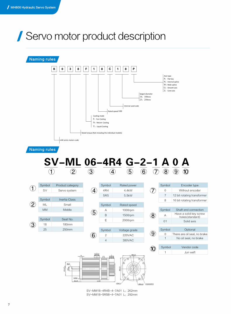
Servo motor product description
SV-MM18-4R4B-4-7A01 L:262mm
SV-MM18-5R5B-4-7A01 L:292mm
SV-ML 06-4R4 G-2-1 A 0 A
Symbol Product category
SV Servo system
Symbol Inertia Class
ML Small
MM Middle
Symbol Seat No.
18 180mm
25 250mm Symbol Voltage grade
2 220VAC
4 380VAC
Symbol Encoder type
0 Without encoder
7 12 bit rotating transformer
8 16 bit rotating transformer
Symbol Rated power
4R4 4.4kW
5R5 5.5kW
Symbol Shaft end connection
AHave a solid key screw
holes(standard)
01 Solid axis
Symbol Optional
0 There are oil seal, no brake
1 No oil seal, no brake
Symbol Vendor code
1 Jun weft
Symbol Rated speed
A 1000rpm
B 1500rpm
E 2000rpm
⑨
⑨
⑩
⑩
⑦
⑦
⑧
⑧
Naming rules
Naming rules
Axis typeP: Flat keyN: Internal splineW: Male splineG: Smooth axisZ: Cone axis
Spigot diameter18:180mm25:250mm
Internal used code
Rated speed/100
Cooling mode
F: Fan Cooling
N: Nature Cooling
Y: Liquid Cooling
Rated torque (Not including the individual models)
mM series motors code
K 0 3 8 F 1 8 C 1 8 P
MH800 Hydraulic Servo System
8
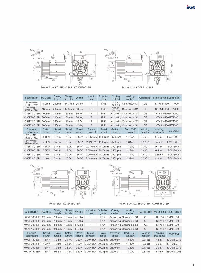
Model Size: K038F18C18P / K036F20C18P Model Size: K058F18C18P
Servo motor product description
Specification PCD sizeCasinglength
Flangediameter
WeightInsulation
classProtection
gradeCooling method
Working method
Certification Motor temperature sensor
SV-MM18-4R4B-4-7A01 180mm 262mm 114.3mm 25.5kg F IP65 Natural
cooling Continuous S1 CE KTY84-130/PT1000
SV-MM18-5R5B-4-7A01 180mm 292mm 114.3mm 30.5kg F IP65 Natural
cooling Continuous S1 CE KTY84-130/PT1000
K038F18C18P 200mm 210mm 180mm 36.2kg F IP54 Air cooling Continuous S1 CE KTY84-130/PT1000
K036F20C18P 200mm 210mm 180mm 36.3kg F IP54 Air cooling Continuous S1 CE KTY84-130/PT1000
K058F18C18P 200mm 245mm 180mm 42.7kg F IP54 Air cooling Continuous S1 CE KTY84-130/PT1000
K060F18C18P 200mm 245mm 180mm 42.6kg F IP54 Air cooling Continuous S1 CE KTY84-130/PT1000
Electrical parameters
Rated power
Rated torque
Rated current
Rated voltage
Torque constant
Rated speed
Maximum speed
Back-EMFconstant
Windingresistor
Windinginductance
EMC/EMI
SV-MM18-4R4B-4-7A01
4.4kW 27Nm 10A 380V 2.7 Nm/A 1500rpm 2500rpm 1.72v/s 0.792Ω 4.83mH IEC61800-3
SV-MM18-5R5B-4-7A01
5.5kW 35Nm 12A 380V 2.9Nm/A 1500rpm 2500rpm 1.81v/s 0.620Ω 4mH IEC61800-3
K038F18C18P 7.5kW 38Nm 12.9A 367V 2.97Nm/A 1800rpm 2500rpm 1.72v/s 0.700Ω 9.3mH IEC61800-3
K036F20C18P 7.5kW 36Nm 17.6A 367V 2.05Nm/A 2000rpm 2500rpm 1.19v/s 0.480Ω 6.5mH IEC61800-3
K058F18C18P 11kW 58Nm 20.0A 367V 2.90Nm/A 1800rpm 2500rpm 1.72v/s 0.410Ω 5.88mH IEC61800-3
K060F18C18P 11kW 58Nm 26.6A 367V 2.18Nm/A 1800rpm 2500rpm 1.31v/s 0.290Ω 4.8mH IEC61800-3
Model Size: K072F18C18P Model Size: K078F20C18P / K091F15C18P
Specification PCD sizeCasinglength
Flangediameter
WeightInsulation
classProtection
gradeCooling method
Working method
Certification Motor temperature sensor
K072F18C18P 200mm 280mm 180mm 49.5kg F IP54 Air cooling Continuous S1 CE KTY84-130/PT1000
K072F20C18P 200mm 280mm 180mm 48.1kg F IP54 Air cooling Continuous S1 CE KTY84-130/PT1000
K078F20C18P 200mm 315mm 180mm 56.9kg F IP54 Air cooling Continuous S1 CE KTY84-130/PT1000
K091F15C18P 200mm 315mm 180mm 56.6kg F IP54 Air cooling Continuous S1 CE KTY84-130/PT1000
Electrical parameters
Rated power
Rated torque
Rated current
Rated voltage
Torque constant
Rated speed
Maximum speed
Back-EMFconstant
Windingresistor
Windinginductance
EMC/EMI
K072F18C18P 13kW 72Nm 26.7A 367V 2.70Nm/A 1800rpm 2500rpm 1.61v/s 0.310Ω 4.8mH IEC61800-3
K072F20C18P 15kW 72Nm 32.0A 367V 2.25Nm/A 2000rpm 2500rpm 1.44v/s 0.260Ω 3.9mH IEC61800-3
K078F20C18P 15kW 72Nm 32.0A 367V 2.25Nm/A 2000rpm 2500rpm 1.34v/s 0.170Ω 2.9mH IEC61800-3
K091F15C18P 15kW 91Nm 30.3A 367V 3.00Nm/A 1500rpm 2200rpm 1.80v/s 0.310Ω 5.0mH IEC61800-3

9
Model Size: K187F18C25P Model Size: K235F20C25P
Specification PCD sizeCasinglength
Flangediameter
WeightInsulation
classProtection
gradeCooling method
Working method
Certification Motor temperature sensor
K187F18C25P 263mm 380mm 250mm 115.1kg F IP54 Air cooling Continuous S1 CE KTY84-130/PT1000
K208F15C25P 263mm 380mm 250mm 115.3kg F IP54 Air cooling Continuous S1 CE KTY84-130/PT1000
K235F20C25P 263mm 460mm 250mm 144.1kg F IP54 Air cooling Continuous S1 CE KTY84-130/PT1000
K290F18C25P 263mm 510mm 250mm 156kg F IP54 Air cooling Continuous S1 CE KTY84-130/PT1000
K341F18C25P 263mm 577mm 250mm 196kg F IP54 Air cooling Continuous S1 CE KTY84-130/PT1000
Electrical parameters
Rated power
Rated torque
Rated current
Rated voltage
Torque constant
Rated speed
Maximum speed
Back-EMFconstant
Windingresistor
Windinginductance
EMC/EMI
K187F18C25P 35kW 187Nm 74.6A 367V 2.58Nm/A 1800rpm 2500rpm 1.59v/s 0.078Ω 2.3mH IEC61800-3
K208F15C25P 27kW 172Nm 58.1A 367V 3.30Nm/A 1500rpm 2000rpm 1.96v/s 0.120Ω 3.2mH IEC61800-3
K235F20C25P 50kW 235Nm 113.0A 367V 2.30Nm/A 2000rpm 2500rpm 1.40v/s 0.050Ω 1.1mH IEC61800-3
K290F18C25P 55kW 290 Nm 114A 380V 2.55Nm/A 1800rpm 2500rpm 1.47v/s 0.031Ω 1.16 mH IEC61800-3
K341F18C25P 61kW 341.6Nm 155.3A 380V 2.20Nm/A 1800rpm 2500rpm 1.34v/s 0.025Ω 1.17mH IEC61800-3
Model Size: K105F20C18P / K111F15C18P Model Size: K132F18C18P
Specification PCD sizeCasinglength
Flangediameter
WeightInsulation
classProtection
gradeCooling method
Working method
Certification Motor temperature sensor
K105F20C18P 200mm 350mm 180mm 63.6kg F IP54 Air cooling Continuous S1 CE KTY84-130/PT1000
K111F15C18P 200mm 350mm 180mm 63.4kg F IP54 Air cooling Continuous S1 CE KTY84-130/PT1000
K132F18C18P 200mm 420mm 180mm 76.6kg F IP54 Air cooling Continuous S1 CE KTY84-130/PT1000
K130F22C18P 200mm 420mm 180mm 76.6kg F IP54 Air cooling Continuous S1 CE KTY84-130/PT1000
Electrical parameters
Rated power
Rated torque
Rated current
Rated voltage
Torque constant
Rated speed
Maximum speed
Back-EMFconstant
Windingresistor
Windinginductance
EMC/EMI
K105F20C18P 22kW 105Nm 45.0A 367V 2.50Nm/A 2000rpm 2500rpm 1.44v/s 0.170Ω 2.8mH IEC61800-3
K111F15C18P 18kW 111Nm 32.8A 367V 3.50Nm/A 1500rpm 2200rpm 2.10v/s 0.290Ω 5.7mH IEC61800-3
K132F18C18P 25kW 132Nm 48.6A 367V 3.00Nm/A 1800rpm 2500rpm 1.76v/s 0.160Ω 2.9mH IEC61800-3
K130F22C18P 25.8kW 112Nm 54.0A 367V 2.40Nm/A 2200rpm 2500rpm 1.42v/s 0.120Ω 2.0mH IEC61800-3
MH800 Hydraulic Servo System

10
Drive terminal layout
CN6
LED displayOperation panel
CN3 port: CAN/485 communication
CN1A port: the I/O output
CN1B port: HMI interface
CN2 port: The encoder interface
CN5 port: the I/O controlJ9 switch: the choice of pressure sensor type

11
Note 1: in the wiring diagram, the digital input signal using the system controller power to drive, CN5 connector’24V power from the external. The power
of the pressure sensor can also be used drive internal power supply. By jumper J1 to 15 v, connect the + 15 v and + 24 v, through the jumper J2 to 15 v,
connect the AGND and GND24V.Drives the factory default J1 and J2 jumper to 15 v side, using drive pressure sensor power supply.
Note 2: the power of the drive pressure sensor is 15 v, to accept the pressure signal is 0 ~ 10 v or 1-5 v voltage signal; You can set the J9 on the circuit
board control.
Note 3: to prevent undesired signal impacting on the drives, it is suggested that all analog signal drives lines and 3-phase input lines of the motor
adopted the shielded cables , with the shielding layer grounded.
Note 4: the encoder lines and communication lines must use twisted-pair shielded cable, shielding layer to ground. Communication line head and
tail should be matching with terminal resistance. The driver CAN communication signal connector has built-in 10 k Ω terminal resistance.485
communication signal connector has a built-in 1 k Ω terminal resistance.
Note 5: prevent jamming signals affect motor temperature sampling, it is recommended to use twisted-pair cable. The driver support two temperature
sensor temperature sampling, KTY84 and Pt1000, by setting the motor temperature sensor parameter selection support type of temperature sensor.
Drive standard wiring diagram
VW
U
R2R1
RST
(+)
PB
Servo driver
Servo motor
Three-phase AC power input
380V
RST
PE
Braking unit or braking resistor
22
21
Cos-Cos+Sin-Sin+
Cos-Cos+Sin-Sin+
R1R2
T2T1
VW
U
Temperature detection signal
Motor three-phase inputAOUT2
AOUT1
AGND
S-ONGND24V
ALM-RST
AIN2+AIN1+
Flow of instructions
Pressure of instructions
Analog output 1Analog output 2
Driver enable
Shunt/confluence of choice
I2
I3
Alarm reset
I4
PID choice 0
PID choice 1
I1Melt the signal
+24V
O2-
O1+O1-
Pressure for output
Wobble-plate output
Double displacement plunger pump
AIN3+Pressure feedback output
AGND+15V
Mains input
PE
Pressure sensor
CAN1HCAN1LCAN1H
CN5
8
42
1
7
3
56
20109
11
12
19
13
O2+
14
1
6
4
7
3
2
1
4
3
CN6
CN2
9
CN3
CAN1L
3
4
10
11
System controller
S-RDY-ALM+ALM-
S-RDY+Servo ready output
Alarm output
15
181716
T2T1
CN1A
CAN2HCAN2LCAN2H
CAN2L
5
6
12
13
485B485A 1
2
485B485A
9
8
7PE
485-+5VAGND
485+7
5
4
2
External HMI
CN1B
14
Common line
Common line
PE
Encoder signal
PE
Fan power input
AC220V
Note 1
Note 1
Note 3
Note 3
Note 3
Note 3
Note 4
Note 4
Note 4
Note 5
MH800 Hydraulic Servo System

12
Single pump control system
Single pump control system
Multiple pump system
Single pump servo system
Driver+Motor+Pump+Parts Power supply
Speed feedbackPressure
Machineoil loop
Oil tankfeedback
P0-10V
Q0-10V
Othersignals
Motor
Servo system
cable
INVT offer complete servo electro-hydraulic combination products:
1. 4.4 ~ 75 kW of electro-hydraulic servo system can completely satisfy the amount of under 500 t injection
molding machine;
2. Can drive the oil pump 16 ~ 160 ml/r, satisfy the system flow of 32 ~ 320 L/min.
PC computer
Oil duct confluence
CAN bus for communication between the controller
Maximum support 16 sets of pump work together,the system flow rate can reach 4000 l/min
Reasonable distribution of the master/slave pump work
13
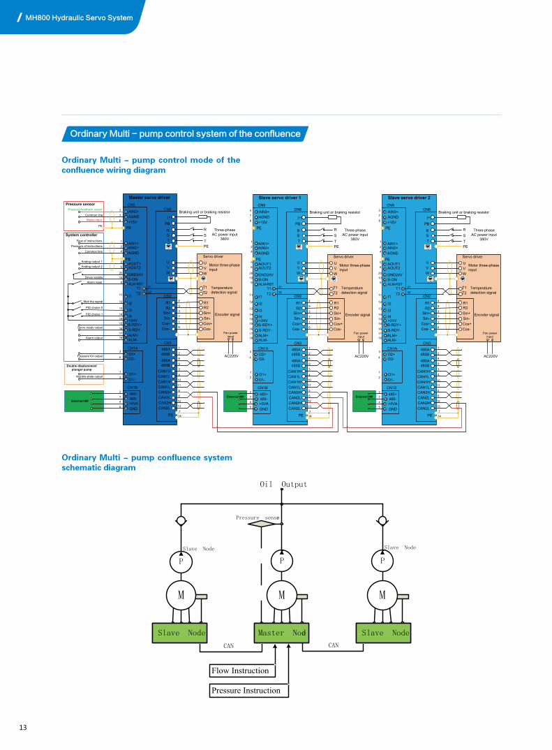
Ordinary Multi - pump control system of the confluence
Ordinary Multi - pump control mode of the confluence wiring diagram
Ordinary Multi - pump confluence system schematic diagram
Slave Node
M
P
Follow Unit
M
Master Node
M
Pressure sensor
PP
Flow Instruction
Pressure Instruction
CAN CAN
Oil Output
Slave Node Slave Node
Master NodeSlave Node Slave Node
VW
U
R2R1
RST
(+)
PB
Master servo driver
Servo driver
Three-phase AC power input
380V
RST
PE
Braking unit or braking resistor
22
21
Cos-Cos+Sin-Sin+
Cos-Cos+Sin-Sin+
R1R2
T2T1
VW
U
Temperature detection signal
Motor three-phase inputAOUT2
AOUT1
AGND
S-ONGND24V
ALM-RST
AIN2+AIN1+
Flow of instructions
Pressure of instructions
Analog output 1Analog output 2
Driver enable
I2
I3
Alarm reset
I4
PID choice 0
PID choice 1
I1Melt the signal
+24V
O2-
O1+O1-
Pressure for output
Wobble-plate output
Double displacement plunger pump
AIN3+Pressure feedback output
AGND+15V
Mains input
PE
Pressure sensor
CAN1HCAN1LCAN1H
CN5
8
42
1
7
3
56
20109
11
12
19
13
O2+
14
1
6
4
7
3
2
1
4
3
CN6
CN2
9
CN3
CAN1L
3
4
10
11
System controller
S-RDY-ALM+ALM-
S-RDY+Servo ready output
Alarm output
15
181716
T2T1
CN1A
CAN2HCAN2LCAN2H
CAN2L
5
6
12
13
485B485A 1
2
485B485A
9
8
7PE
485-+5VAGND
485+7
5
4
2
External HMI
CN1B
14
Common line
Common line
PE
Encoder signal
PE
Fan power input
AC220V
VW
U
R2R1
RST
(+)
PB
Slave servo driver 1
Servo driver
Three-phase AC power input
380V
RST
PE
Braking unit or braking resistor
22
21
Cos-Cos+Sin-Sin+
Cos-Cos+Sin-Sin+
R1R2
T2T1
VW
U
Temperature detection signal
Motor three-phase inputAOUT2
AOUT1
AGND
S-ONGND24V
ALM-RST
AIN2+AIN1+
I2
I3I4
I1
+24V
O2-
O1+O1-
AIN3+AGND+15V
PE
CAN1HCAN1LCAN1H
CN5
8
42
1
7
3
56
20109
11
12
19
13
O2+
14
1
6
4
7
3
2
1
4
3
CN6
CN2
9
CN3
CAN1L
3
4
10
11
S-RDY-ALM+ALM-
S-RDY+15
181716
T2T1
CN1A
CAN2HCAN2LCAN2H
CAN2L
5
6
12
13
485B485A 1
2
485B485A
9
8
7PE
485-+5VAGND
485+7
5
4
2CN1B
14
Encoder signal
PE
Fan power input
AC220V
External HMI
VW
U
R2R1
RST
(+)
PB
Slave servo driver 2
Servo driver
Three-phase AC power input
380V
RST
PE
Braking unit or braking resistor
22
21
Cos-Cos+Sin-Sin+
Cos-Cos+Sin-Sin+
R1R2
T2T1
VW
U
Temperature detection signal
Motor three-phase inputAOUT2
AOUT1
AGND
S-ONGND24V
ALM-RST
AIN2+AIN1+
I2
I3I4
I1
+24V
O2-
O1+O1-
AIN3+AGND+15V
PE
CAN1HCAN1LCAN1H
CN5
8
42
1
7
3
56
20109
11
12
19
13
O2+
14
1
6
4
7
3
2
1
4
3
CN6
CN2
9
CN3
CAN1L
3
4
1011
S-RDY-ALM+ALM-
S-RDY+15
181716
T2T1
CN1A
CAN2HCAN2LCAN2H
CAN2L
5
6
12
13
485B485A 1
2
485B485A
9
8
7PE
485-+5VAGND
485+7
5
4
2CN1B
14
Encoder signal
PE
Fan power input
AC220V
External HMI
MH800 Hydraulic Servo System

14
The compound mode and multi-mode control system of the confluence
The compound mode and multi-mode control mode of the confluence wiring diagram
Composite pattern control system diagram
Slave Node
M
P
Slave Node
M
Master Node
M
Pressure sensor
PP
Flow Instruction 1
Pressure Instruction 1
CAN CAN
Oil Output 1
Pressure sensor Pressure sensor
Flow Instruction 2
Pressure Instruction 2
Flow Instruction 3
Pressure Instruction 3
Oil Output 2 Oil Output 3
VW
U
R2R1
RST
(+)
PB
Slave servo driver 1
Servo driver
Three-phase AC power input
380V
RST
PE
Braking unit or braking resistor
22
21
Cos-Cos+Sin-Sin+
Cos-Cos+Sin-Sin+
R1R2
T2T1
VW
U
Temperature detection signal
Motor three-phase inputAOUT2
AOUT1
AGND
S-ONGND24V
ALM-RST
AIN2+AIN1+
Flow of instructions
Pressure of instructions
Analog output 1Analog output 2
Driver enable
Shunt/confluence of choice
I2
I3
Alarm reset
I4
PID choice 0
PID choice 1
I1Melt the signal
+24V
O2-
O1+O1-
Pressure for output
Wobble-plate output
Double displacement plunger pump
AIN3+Pressure feedback output
AGND+15V
Mains input
PE
Pressure sensor CN5
8
42
1
7
3
56
20109
11
12
19
13
O2+
14
1
6
4
7
3
2
1
4
3
CN6
CN2
9
System controller
S-RDY-ALM+ALM-
S-RDY+Servo ready output
Alarm output
15
181716
T2T1
CN1A
485-+5VAGND
485+7
5
4
2
External HMI
CN1B
Common line
Common line
PE
Encoder signal
PE
Fan power input
AC220V
VW
U
R2R1
RST
(+)
PB
Slave servo driver 2
Servo driver
Three-phase AC power input
380V
RST
PE
Braking unit or braking resistor
22
21
Cos-Cos+Sin-Sin+
Cos-Cos+Sin-Sin+
R1R2
T2T1
VW
U
Temperature detection signal
Motor three-phase inputAOUT2
AOUT1
AGND
S-ONGND24V
ALM-RST
AIN2+AIN1+
Flow of instructions
Pressure of instructions
Analog output 1Analog output 2
Driver enable
Shunt/confluence of choice
I2
I3
Alarm reset
I4
PID choice 0
PID choice 1
I1Melt the signal
+24V
O2-
O1+O1-
Pressure for output
Wobble-plate output
Double displacement plunger pump
AIN3+Pressure feedback output
AGND+15V
Mains input
PE
Pressure sensor CN5
8
42
1
7
3
56
20109
11
12
19
13
O2+
14
1
6
4
7
3
2
1
4
3
CN6
CN2
9
System controller
S-RDY-ALM+ALM-
S-RDY+Servo ready output
Alarm output
15
181716
T2T1
CN1A
485-+5VAGND
485+7
5
4
2
External HMI
CN1B
Common line
Common line
PE
Encoder signal
PE
Fan power input
AC220V
VW
U
R2R1
RST
(+)
PB
Master servo driver
Servo driver
Three-phase AC power input
380V
RST
PE
Braking unit or braking resistor
22
21
Cos-Cos+Sin-Sin+
Cos-Cos+Sin-Sin+
R1R2
T2T1
VW
U
Temperature detection signal
Motor three-phase inputAOUT2
AOUT1
AGND
S-ONGND24V
ALM-RST
AIN2+AIN1+
Driver enable
Shunt/confluence of choice
I2
I3
Alarm reset
I4
PID choice 0
PID choice 1
I1Melt the signal
+24V
O2-
O1+O1-
Pressure for output
Wobble-plate output
Double displacement plunger pump
AIN3+
AGND+15V
PE
Pressure sensorCN5
8
42
1
7
3
56
20109
11
12
19
13
O2+
14
1
6
4
7
3
2
1
4
3
CN6
CN2
9
S-RDY-ALM+ALM-
S-RDY+Servo ready output
Alarm output
15
181716
T2T1
CN1A
485-+5VAGND
485+7
5
4
2
External HMI
CN1B
PE
Encoder signal
PE
Fan power input
AC220V
CAN1HCAN1LCAN1H
CN3
CAN1L
3
4
10
11
CAN2HCAN2LCAN2H
CAN2L
5
6
12
13
485B485A 1
2
485B485A
9
8
7PE 14
CAN1HCAN1LCAN1H
CN3
CAN1L
3
4
10
11
CAN2HCAN2LCAN2H
CAN2L
5
6
12
13
485B485A 1
2
485B485A
9
8
7PE 14
CAN1HCAN1LCAN1H
CN3
CAN1L
3
4
10
11
CAN2HCAN2LCAN2H
CAN2L
5
6
12
13
485B485A 1
2
485B485A
9
8
7PE 14
Flow of instructions
Pressure of instructions
Analog output 1
Analog output 2
Pressure feedback output
Mains input
System controller
Common line
Common line

15
Multi-mode control system diagram
Multi-mode control system diagram
Slave Node
M
P
Independent units
M
Master Node
M
Pressure sensor
PP
Flow Instruction 1
Pressure Instruction 1
CAN CAN
Oil Output 1
Pressure sensor Pressure sensor
Flow Instruction 2
Pressure Instruction 2
Flow Instruction 3
Pressure Instruction 3
Oil Output 2 Oil Output 3
Slave Node
M
P
Slave Node
M
P
Slave NodeSlave Node Master Node
Control Unit Follow Unit Control Unit Follow Unit Independent units
AIN1 AIN2AOUT2 AOUT1 S_RDYI7 AIN1 AIN2AOUT2 AOUT1 S_RDYI7
Slave Node Master Node Slave Node
PT PT PT
CAN
CAN CAN
P2
Q2
C/D
S/ON
P1
Q1
C/D
S/ON
P3
Q3
C/D
S/ONS/ONS/ON
PT: Pressure Sensor
Q1-3: Flower Instruction
P1-3: Pressure Instruction
C/D:Confluence/shunt signal
S/ON: Drive enable
I7: Digital Input7 AIN1 AIN2: Instruction input
AOUT1 AOUT2: Analog Output S_RDY: Servo is ready
MH800 Hydraulic Servo System

KINWAY
System flow(L/min)
System pressure(MPa)
Pump series: HG Sunny pump
QT Sumitomo pump
Oil pump type:1 Single pump
2 Double pump
16
Hydraulic servo configuration tables
The naming rules of hydraulic configuration
Hydraulic servo standard configuration table
KT-110-18-HG-1
MH800 HYDRAULIC SERVO SYSTEM
Injection molding machine Servo Retrofit configuration set
System type System flow(L/min) System pressure (bar) Pump model Servo motor model Servo driver model
KT-017-25-HG-1 17 250bar HG0-08 MM18-2R7B-4-7A0 MH800-4R4-33
KT-022-25-HG-1 22 250bar HG0-10 MM18-3R0B-4-7A0 MH800-4R4-33
KT-028-25-HG-1 28 250bar HG0-13 MM18-4R4B-4-7A0 MH800-5R5-33
KT-035-18-HG-1 35 175bar HG0-16 MM18-4R4B-4-7A0 MH800-4R4-33
KT-035-25-HG-1 35 250bar HG0-16 MM18-5R5B-4-7A0 MH800-5R5-33
KT-044-18-HG-1 44 175bar HG0-20 MM18-5R5B-4-7A0 MH800-5R5-33
KT-044-25-HG-1 44 250bar HG0-20 MM18-7R5B-4-7A0 MH800-7R5-33
KT-055-18-HG-1 55 175bar HG1-25 K036F20C18P MH800-7R5-33
KT-055-25-HG-1 55 250bar HG1-25 K060F18C18P MH800-011-33
KT-070-18-HG-1 70 175bar HG1-32-01 K060F18C18P MH800-011-33
KT-088-18-HG-1 88 175bar HG1-40-01 K072F18C18P MH800-015-33
KT-110-18-HG-1 110 175bar HG1-50-01 K078F20C18P MH800-018-33
KT-132-16-HG-1 132 160bar HG1-63-01 K105F20C18P MH800-018-33
KT-132-18-HG-1 132 175bar HG1-63-01 K132F18C18P MH800-018-33
KT-160-16-HG-1 160 160bar HG2-80-01 K132F18C18P MH800-025-33
KT-160-18-HG-1 160 175bar HG2-80-01 K132F18C18P MH800-030-33
KT-200-14-HG-1 200 140bar HG2-100-01 K208F15C25P MH800-030-33
KT-200-16-HG-1 200 160bar HG2-100-01 K187F18C25P MH800-037-33
KT-200-18-HG-1 200 175bar HG2-100-01 K235F20C25P MH800-037-33
KT-250-14-HG-1 250 140bar HG2-125-01 K235F20C25P MH800-037-33
KT-250-18-HG-1 250 175bar HG2-125-01 K235F20C25P MH800-045-33
KT-300-14-HG-1 300 140bar HG2-160-01 K235F20C25P MH800-045-33
KT-300-16-HG-1 300 160bar HG2-160-01 K290F18C25P MH800-055-33
KT-300-18-HG-1 300 175bar HG2-160-01 K341F18C25P MH800-055-33
17 34
rev/minin
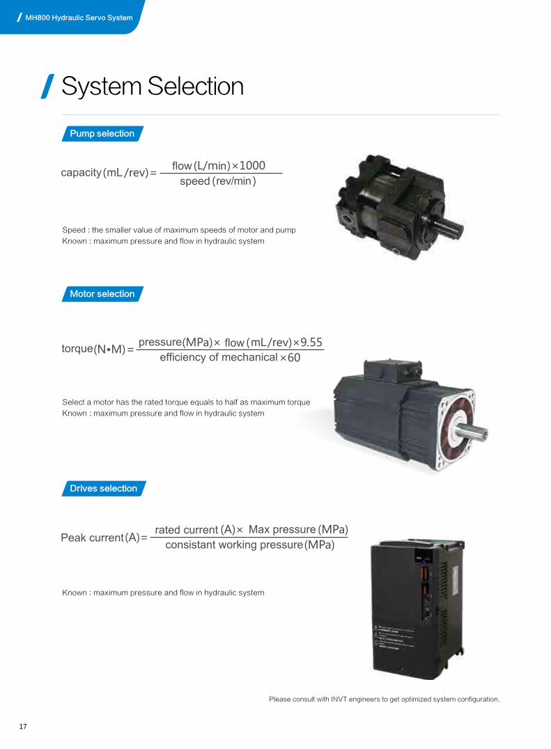
Speed : the smaller value of maximum speeds of motor and pump
Known : maximum pressure and flow in hydraulic system
Select a motor has the rated torque equals to half as maximum torque
Known : maximum pressure and flow in hydraulic system
Known : maximum pressure and flow in hydraulic system
Please consult with INVT engineers to get optimized system configuration.
Pump selection
Motor selection
Drives selection
System Selection
MH800 Hydraulic Servo System

18
Servo Hydraulic system energy-saving rate is determined by Dwell &Cooling time in the molding cycle. Normally the power consumption rate is between 20%~80%.
Hydraulic servo configuration tables
34
rev/minin
Please consult with INVT engineers to get optimized system configuration.

1519
Injection molding machine
Die casting machine
Product application
MH800 Hydraulic Servo System
1620
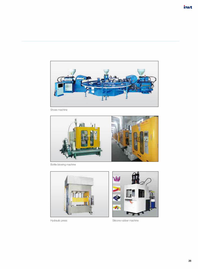
Shoes machine
Bottle blowing machine
Hydraulic press Silicone rubber machine

21
MH800 Hydraulic Servo System

22

MH800 Hydraulic Servo System
Perfect combination of servo and solution
http://
Scan, landing INVT mobile website