mi 291 chapter 3 (reverse engineering)(1)
TRANSCRIPT
Chapter 3 Reverse Engineering
Definition: Reverse Engineering
Reverse engineering is opposite to forward engineering. Works with existing product to create CAD model and modify or reproduce
the design aspect of the product. Can also be defined as duplicating an existing product by capturing its
physical dimensions. Reverse engineering is also defined as the process of obtaining a geometric
CAD model from 3-D points acquired by scanning/digitizing existing parts/products.
Reverse engineering helps in redesigning a component for better
maintainability and also to reproduce a system without access to its design documents.
Introduction
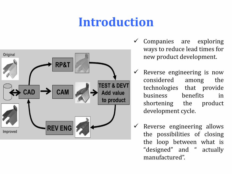
Companies are exploring ways to reduce lead times for new product development.
Reverse engineering is now
considered among the technologies that provide business benefits in shortening the product development cycle.
Reverse engineering allows
the possibilities of closing the loop between what is “designed” and “ actually manufactured”.
What is Reverse Engineering ?
Engineering is the process of designing, manufacturing, assembling and maintaining products & systems.
Forward engineering : is the traditional process of moving from logical designs to the manufactured and assembled systems. In some situations, may be product are available without any technical details e.g. drawing, bills of material or without engineering data.
Reverse engineering : process of duplicating an existing part, subassembly, or product, without drawings, documentation is known as reverse engineering.
Reverse Engineering a Solution
As products become more organic in shape designing in CAD becomes more challenging without any guarantee that the CAD design will replicate the sculpted model exactly.
Reverse engineering can be considered as an optimal solution to the above problem.
The physical model is the source of information for the CAD in the reverse engineering.
Reverse engineering also helps in compressing the product development lead time.

The process is also referred as physical to digital process. Example: injection molding companies explore ways to reduce the design
development time of tool and die. Reverse engineering helps in transferring a physical product or clay mock
up in digital form. Digital form can be easily remodeled and exported for rapid prototyping or rapid manufacturing.
Why Use Reverse Engineering ?
The original manufacturer no longer exists, but a customer needs the product, e.g. , aircraft spares required typically after an aircraft has been in service for several years.
The original manufacturer of a product no longer produces the
product, e.g. , the original product has become obsolete. The original product design documentation has been lost or
never existed. Creating data to refurbish or manufacture a part for which there
are no CAD data, or for which the data have become obsolete or lost.
Inspection and/or Quality Control–Comparing a fabricated part
to its CAD description or to a standard item.
Cont……
Some bad features of a product need to be eliminated e.g. , excessive wear might indicate where a product should be improved.
Strengthening the good features of a product based on long-term usage.
Analyzing the good and bad features of competitors’ products.
Exploring new avenues to improve product performance and features.
Creating 3-D data from a model or sculpture for animation in games and movies.
Cont…… Creating 3-D data from an individual, model or sculpture to
create, scale, or reproduce artwork.
Architectural and construction documentation and measurement.
Fitting clothing or footwear to individuals and determining the anthropometry of a population.
Generating data to create dental or surgical prosthetics, tissue engineered body parts, or for surgical planning.
Documentation and reproduction.
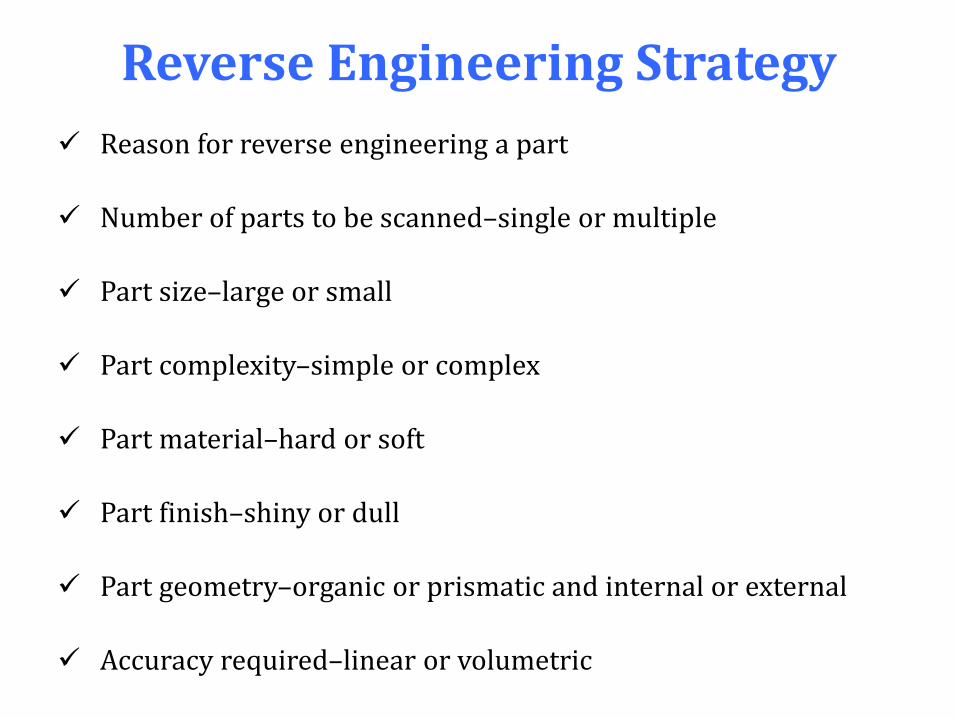
Reverse Engineering Strategy
Reason for reverse engineering a part
Number of parts to be scanned–single or multiple
Part size–large or small
Part complexity–simple or complex
Part material–hard or soft
Part finish–shiny or dull
Part geometry–organic or prismatic and internal or external
Accuracy required–linear or volumetric
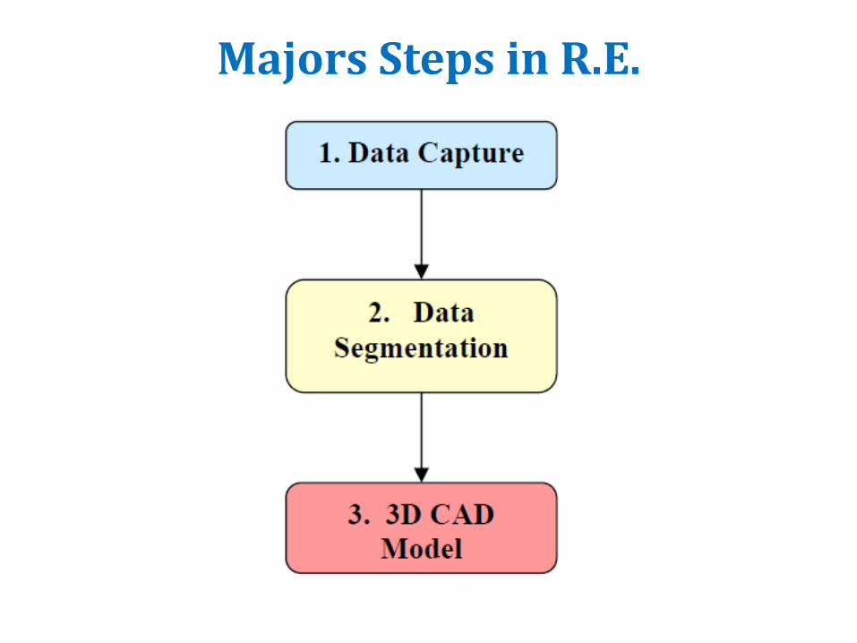
Majors Steps in R.E.
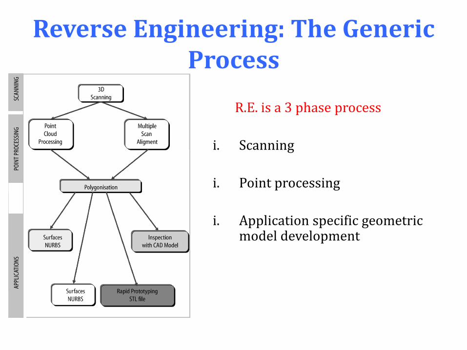
Reverse Engineering: The Generic Process
R.E. is a 3 phase process
i. Scanning
i. Point processing
i. Application specific geometric model development

Scanning Phase Selection of correct scanner. Preparing the part to be scanned. Scanning to capture geometric details e.g. steps, slots, pockets
and holes. 3D scanners for scanning part geometry, producing clouds of
points to define surface profile. Two types of scanners.
i. Contact ii. Non-contact
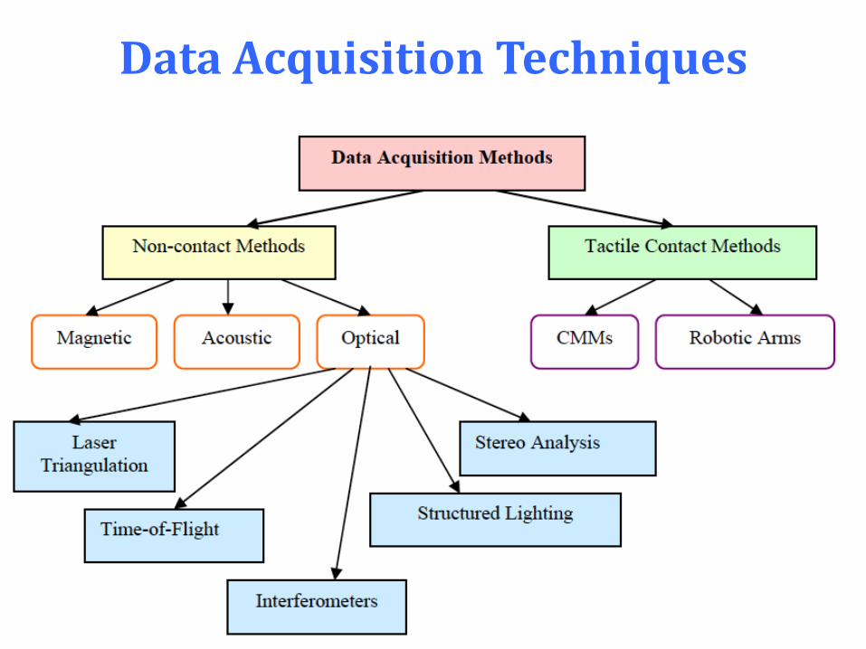
Data Acquisition Techniques

Contact Scanner
Contact probes automatically follow contours of a physical surface.
Probe devices are based on CMM technologies, tolerance range 0.01-0.02mm
Speed of scanning is function of size of part, generally slow for large parts.
Tactile device probes must deflect to register a point, a degree of contact pressure is required.
Restrictions with contact pressure limits the use of this technology for soft materials.
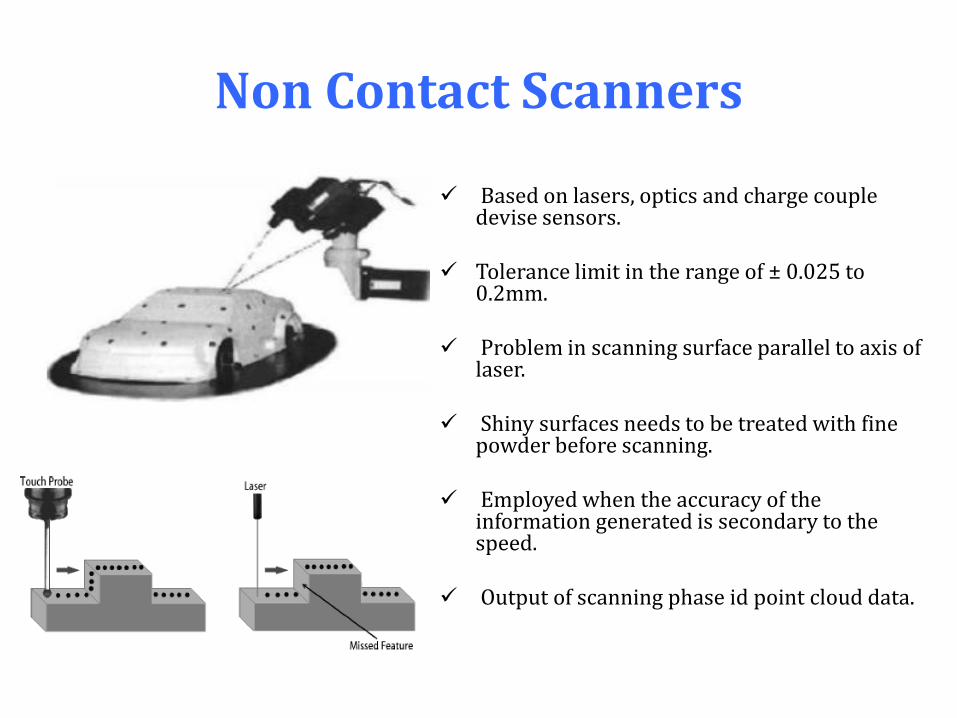
Non Contact Scanners
Based on lasers, optics and charge couple devise sensors.
Tolerance limit in the range of ± 0.025 to
0.2mm. Problem in scanning surface parallel to axis of
laser. Shiny surfaces needs to be treated with fine
powder before scanning. Employed when the accuracy of the
information generated is secondary to the speed.
Output of scanning phase id point cloud data.

Laser Triangulation
Location & angles between light source & photo sensing devices to configure position coordinates.
Light is focused at a predefined
angle on the surface. Photosensitive device captures the
reflected light & using geometric triangulation the coordinates of surface is recorded.
Light source and photosensitive
device is normally mounted on moving platform to enable multiple scans.
Accuracy of scan depends on the
resolution of the photosensitive device & the distance between the surface & scanner.
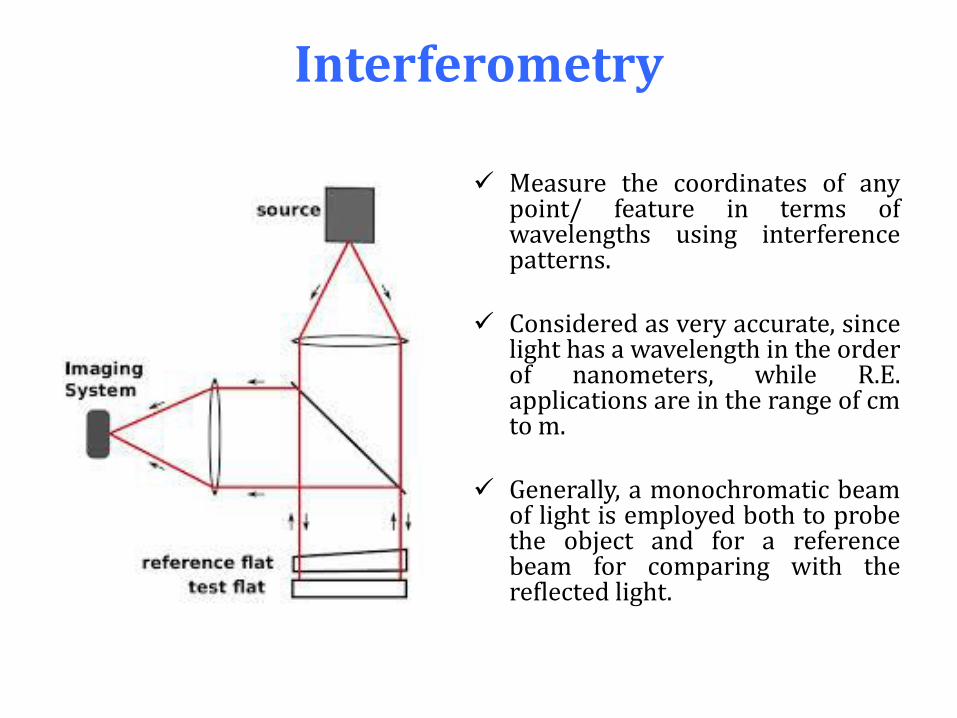
Interferometry
Measure the coordinates of any point/ feature in terms of wavelengths using interference patterns.
Considered as very accurate, since
light has a wavelength in the order of nanometers, while R.E. applications are in the range of cm to m.
Generally, a monochromatic beam
of light is employed both to probe the object and for a reference beam for comparing with the reflected light.
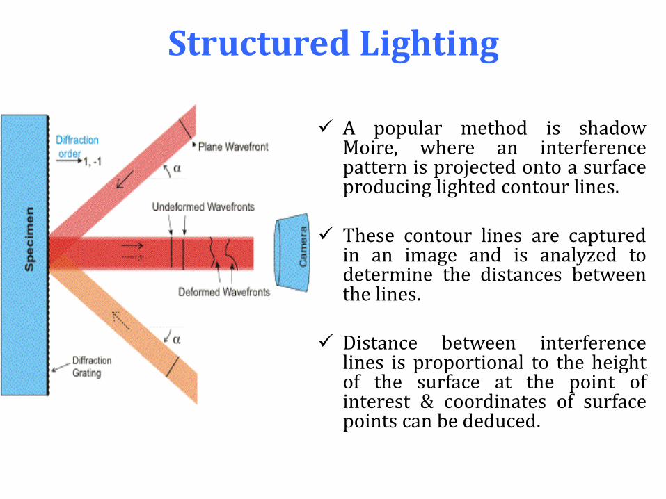
Structured Lighting
A popular method is shadow Moire, where an interference pattern is projected onto a surface producing lighted contour lines.
These contour lines are captured
in an image and is analyzed to determine the distances between the lines.
Distance between interference
lines is proportional to the height of the surface at the point of interest & coordinates of surface points can be deduced.
Stereo Image Analysis Relative locations of landmarks in multiple images are related to
position coordinates of points of interest. Method is similar structured lighting method. Image frames are analyzed to determine coordinate data. Analysis does not rely on projected patterns, but, stereo pairs are used
to infer information to determine coordinates. Referred as passive method, as no structured light is employed. Correlation of image pairs & landmarks with the help of images is
considered as a complex procedure hence active methods have preference.

Other Methods ACOUSTIC Sound is reflected from a surface. Essentially the same as time of flight Distance between surface & source is measured with known speed of
sound.
MAGNETIC FIELD Involves sensing the strength of magnetic field source. Magnetic touch probes are employed of sensing the location and
orientation of a stylus within the field.
HYBRID Combination of contact & non-contact systems.
Non Contact Scanners: Advantages
No physical contact.
Fast digitizing of substantial volumes.
Good accuracy and resolution for common applications.
Ability to detect colors.
Ability to scan highly detailed objects, where mechanical touch probes may be too large to accomplish the task.

Non-Contact Scanning : Challenges
Calibration
Accuracy
Accessibility
Occlusion
Fixture (placement)
Multiple views
Noise and incomplete data
Statistical distributions of parts
Surface finish
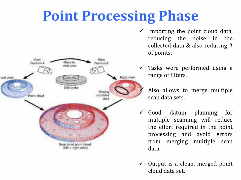
Point Processing Phase Importing the point cloud data,
reducing the noise in the collected data & also reducing # of points.
Tasks were performed using a range of filters.
Also allows to merge multiple scan data sets.
Good datum planning for multiple scanning will reduce the effort required in the point processing and avoid errors from merging multiple scan data.
Output is a clean, merged point cloud data set.
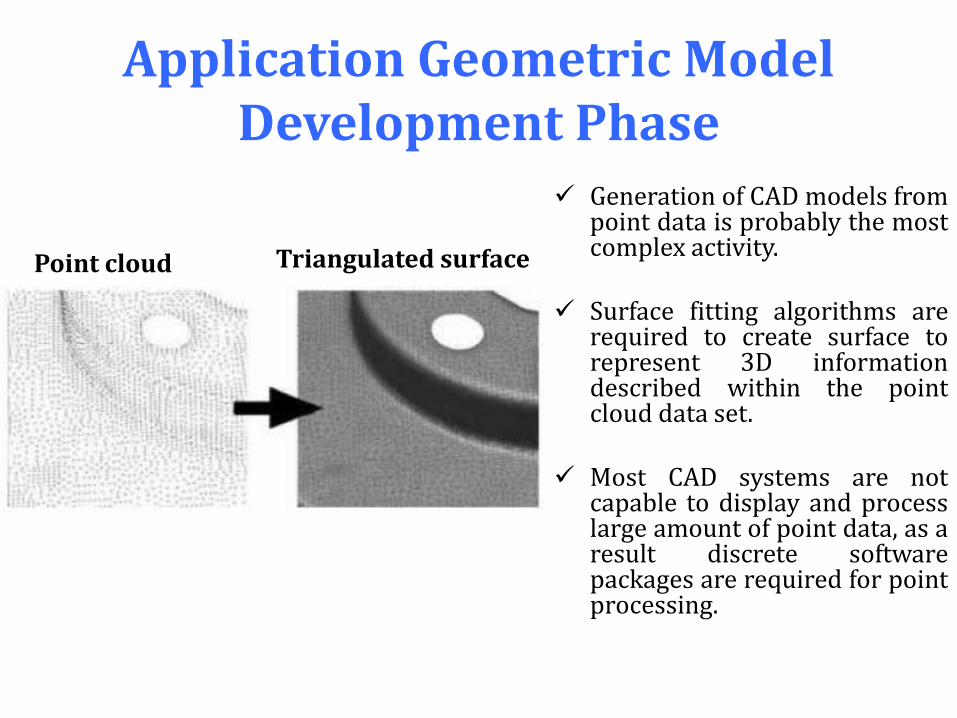
Application Geometric Model Development Phase
Generation of CAD models from point data is probably the most complex activity.
Surface fitting algorithms are
required to create surface to represent 3D information described within the point cloud data set.
Most CAD systems are not
capable to display and process large amount of point data, as a result discrete software packages are required for point processing.
Point cloud Triangulated surface
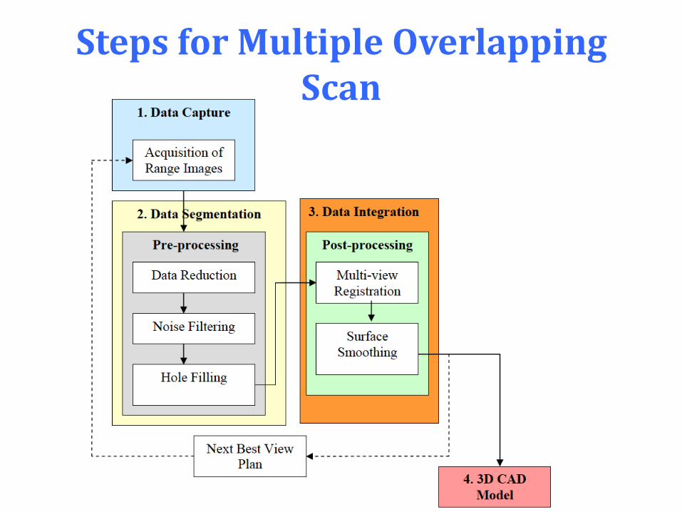
Steps for Multiple Overlapping Scan
Is Project Suitable for R.E. ? How will the team perform the investigation? What constraints have to be dealt with in analyzing the artifact? What plan will best unravel the artifact’s function and design
features? What types of plots or graphical displays will best communicate
discoveries about the object’s function? How was it manufactured? What is the consumer population? Are design improvements possible? What kind of an ad or commercial will be suited for the object?
Reverse Engineering: Applications
Frisbee Aluminum can Wind-up toy robot Disposable camera Stapler Climbing rope Coffee maker Thermos
Ski binding
Water gun
Lighter
Match
Bicycle light system
Audio speakers
Shock absorber

Aluminum Can : Procedure
i. Measured dimensions
ii. weight
iii. flow
iv. rates (wide mouth, narrow mouth),
v. force (required to open)
vi. load (to deform and to explode).
vii. The deformation force defines the critical axial buckling load.
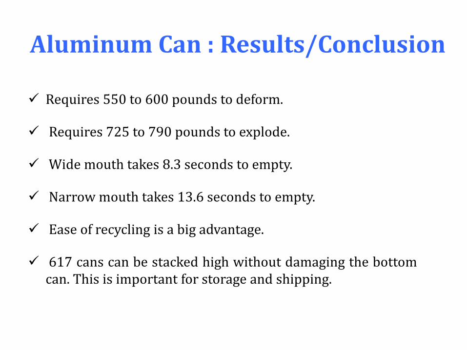
Aluminum Can : Results/Conclusion
Requires 550 to 600 pounds to deform.
Requires 725 to 790 pounds to explode.
Wide mouth takes 8.3 seconds to empty.
Narrow mouth takes 13.6 seconds to empty.
Ease of recycling is a big advantage.
617 cans can be stacked high without damaging the bottom can. This is important for storage and shipping.
The Match : Procedure
i. Studied history.
i. Measured the burn time of matches of different lengths as a function of angle.
i. The critical angle to hold a match in the wind (a fan was used).
i. The striking force and match angle (an air track was used).
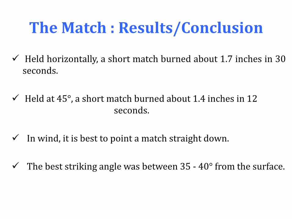
The Match : Results/Conclusion
Held horizontally, a short match burned about 1.7 inches in 30 seconds.
Held at 45°, a short match burned about 1.4 inches in 12 seconds.
In wind, it is best to point a match straight down.
The best striking angle was between 35 - 40° from the surface.
The Toaster : Procedure
i. Dissected object.
i. measured dimensions.
i. Measured temperature and time at each setting.
i. Measured electrical resistance.
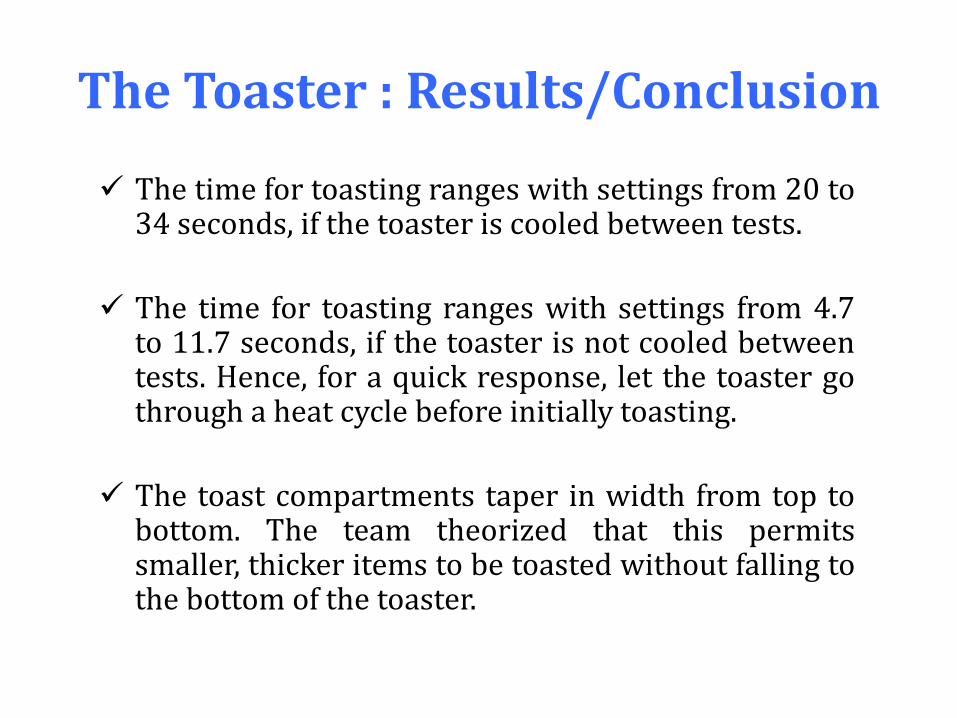
The Toaster : Results/Conclusion
The time for toasting ranges with settings from 20 to 34 seconds, if the toaster is cooled between tests.
The time for toasting ranges with settings from 4.7 to 11.7 seconds, if the toaster is not cooled between tests. Hence, for a quick response, let the toaster go through a heat cycle before initially toasting.
The toast compartments taper in width from top to bottom. The team theorized that this permits smaller, thicker items to be toasted without falling to the bottom of the toaster.
R.E. : Project Report Background:
Describe what need the device fulfills. Give a brief history of the
design. Include any accompanying literature as an appendix.
Project Goals:
List the goals for performing the reverse-engineering study; i.e.,
what will be learned from the study?
Test and Analysis Procedures:
Describe the procedures used to address the above goals. How was
the device and its components evaluated? Document test data
obtained.
Dissection Details:
Describe (using drawings, photos and/or video where appropriate)
the key components and how they function.
Results:
Describe what was learned about this device’s design and
functionality. Provide suggestions for changes that would improve its
function or make it more cost effective to produce. Provide
suggestions for any changes that would make it “greener” or more
universally available.
Marketing:
Include either an advertisement (in print) or a video or radio
commercial, marketing this artifact to an identified target group of
potential customers.