microsoft hyper v recommended practices for hitachi compute blade 2000 and hus
DESCRIPTION
hdsTRANSCRIPT
Recommended Practices
Microsoft Hyper-V Recommended Practices for Hitachi Compute Blade 2000 and Hitachi Unified Storage
Apr
By
Rick Andersenil 19, 2012
Feedback
Hitachi Data Systems welcomes your feedback. Please share your thoughts by sending an email message to [email protected]. Be sure to include the title of this white paper in your email message.
Table of Contents
Solution Components ......................................................................................................2Hitachi Unified Storage .........................................................................................2Hitachi Compute Blade 2000 .................................................................................2Hitachi Dynamic Link Manager .............................................................................2Hitachi Dynamic Provisioning ................................................................................3Hitachi Storage Navigator Modular 2 ....................................................................3Hitachi Performance Monitor .................................................................................4Microsoft Hyper-V .................................................................................................4
Storage Configuration Best Practices ............................................................................5
Redundancy ..........................................................................................................7Zone Configuration ...............................................................................................7Storage Host Group Configuration ........................................................................8
Hyper-V Storage Deployment Options .........................................................................12
Disk Type.............................................................................................................12Disk Interface.......................................................................................................14
Hyper-V Storage Provisioning.......................................................................................15
I/O Redirection.....................................................................................................17Dedicated VHD Deployment................................................................................18Shared VHD Deployment ....................................................................................19Pass-through Disk Deployment ..........................................................................21Cluster Shared Volume Deployment ...................................................................23
iSCSI Storage Deployment ............................................................................................25
Direct Connection ................................................................................................25Dual Connection ..................................................................................................27
Storage Sizing ................................................................................................................30
Selecting Child Partition Storage .........................................................................30Determine the LU Size ........................................................................................31Number of Virtual Machines per VHD LU or CSV LU..........................................32
Hyper-V Protection Strategies.......................................................................................34
Backups ...............................................................................................................34Protection for Cluster Shared Volumes ...............................................................35Storage Replication .............................................................................................37Hyper-V Quick Migration and Live Migration .......................................................37Hitachi Storage Cluster........................................................................................38Performance Monitoring ......................................................................................39

1
1
Microsoft Hyper-V Recommended Practices for Hitachi Compute Blade 2000 and Hitachi Unified StorageRecommended Practices
Hitachi Unified Storage offer robust storage solutions that reduce setup and management costs and eliminate performance bottlenecks when using Hyper-V in Microsoft Windows Server 2008 environments. This is accomplished using the following:
Advanced point-to-point SAS-based architecture for concurrent back-end I/O capacity
Symmetric active-active front-end architecture that dynamically spreads I/O workloads across resources and allows I/O through any path
Virtualization achieves several important objectives:
Increased return on investment by eliminating underutilization of hardware and reducing administration overhead
Decreased total cost of operation by reducing data center space and energy usage
Improved operational efficiencies by increasing availability and performance of critical applications and simplifying deployment and migration of those applications
Improved responsiveness to the constantly changing business climate
Become more environmentally friendly.
While virtualization offers many benefits, it also brings risks. Improper deployment of storage and applications can have catastrophic consequences due to the highly consolidated nature of virtualized environments. Mitigate these risks by adopting a new way of thinking about storage infrastructure and application deployment.
This paper is intended for use by IT administrators who plan storage for a Hyper-V deployment. It provides guidance on how to configure the Hyper-V environment and Hitachi Unified Storage to achieve the best performance, scalability, and availability.

2
2
Solution ComponentsThese are the key components described in this recommended practices paper.
Hitachi Unified Storage Hitachi Unified Storage is a midrange storage platform for all data. It helps businesses meet their service level agreements for availability, performance, and data protection.
The performance of Hitachi Unified Storage is reliable, scalable, and available for block and file data. It is simple to manage, optimized for critical business applications, and more efficient.
Use Unified Storage for a lower investment in storage. Deploy this storage, which grows to meet expanding requirements and service level agreements, for critical business applications. Simplify your operations with integrated set-up and management for a quicker time to value.
Unified Storage enables extensive cost savings through file and block consolidation to build a cloud infrastructure at your own pace to deliver your services.
Hitachi Compute Blade 2000Hitachi Compute Blade 2000 is an enterprise-class blade server platform. It features the following:
A balanced system architecture that eliminates bottlenecks in performance and throughput
Configuration flexibility
Eco-friendly power-saving capabilities
Fast server failure recovery using a N+1 cold standby design that allows replacing failed servers within minutes
For more information, see Hitachi Compute Blade Family on the Hitachi Data Systems website.
Hitachi Dynamic Link Manager Hitachi Dynamic Link Manager, used for SAN multipathing, is configured using its round-robin multipathing policy. This policy automatically selects a path by rotating through all available paths. The round-robin multipathing policy balances the load across all available paths, optimizing IOPS and response time.
For more information, see Hitachi Dynamic Link Manager on the Hitachi Data Systems website.

3
3
Hitachi Dynamic ProvisioningOn Hitachi storage devices, Hitachi Dynamic Provisioning provides wide striping and thin provisioning functionalities.
Using Hitachi Dynamic Provisioning is like using a host-based logical volume manager (LVM), but without incurring host processing overhead. It provides one or more wide-striping pools across many RAID groups. Each pool has one or more dynamic provisioning virtual volumes (DP-VOLs) of a logical size you specify of up to 60TB created against it without allocating any physical space initially.
Deploying Hitachi Dynamic Provisioning avoids the routine issue of hot spots that occur on logical devices (LDEVs). These occur within individual RAID groups when the host workload exceeds the IOPS or throughput capacity of that RAID group. This distributes the host workload across many RAID groups, which provides a smoothing effect that dramatically reduces hot spots.
When used with Hitachi Unified Storage, Hitachi Dynamic Provisioning has the benefit of thin provisioning. Physical space assignment from the pool to the DP-VOL happens as needed using 1 GB chunks, up to the logical size specified for each DP-VOL. There can be a dynamic expansion or reduction of pool capacity without disruption or downtime. You can rebalance an expanded pool across the current and newly added RAID groups for an even striping of the data and the workload.
For more information, see the Hitachi Dynamic Provisioning datasheet and Hitachi Dynamic Provisioning on the Hitachi Data Systems website.
Hitachi Storage Navigator Modular 2 Hitachi Storage Navigator Modular 2 enables essential management and optimization of storage system functions. Using Java agents, Storage Navigator Modular 2 runs on most browsers. A command line interface is available.
Use Storage Navigator Modular 2 for the following:
RAID-level configurations
LUN creation and expansion
Online microcode updates and other system maintenance functions
Performance metrics
For more information, see Hitachi Storage Navigator Modular 2 on the Hitachi Data Systems website.
4
4
Hitachi Performance MonitorHitachi Performance Monitor is a controller-based software application, available through Hitachi Storage Navigator Modular 2. This monitors the performance of RAID groups, logical units, and other elements of the storage system. It also tracks utilization rates of resources, such as hard disk drives and processors. Information displays graphically in a Performance Monitor window.
Microsoft Hyper-V Microsoft Hyper-V is a hypervisor-based virtualization technology integrated into Microsoft Windows Server 2008 x64. Hyper-V allows you to run multiple operating systems on a single physical server. Enabling the Hyper-V role in Windows Server 2008 provides the following functions:
Hypervisor
Parent and child partitions
Integration services
Emulated and synthetic devices
Microsoft Windows HypervisorThe Microsoft Windows Hypervisor is a thin software layer that allows multiple operating systems to run simultaneously on a single physical server. It is the core component of Hyper-V. The Windows Hypervisor creates and manages partitions that allow for isolated execution environments. The Windows Hypervisor runs directly on top of the hardware platform, with the operating systems running on top.
Parent and Child PartitionsTo run multiple virtual machines with isolated execution environments on a physical server, Hyper-V technology uses a logical entity called a partition. A partition is where the operating system and its applications execute. Hyper-V defines two kinds of partitions, parent and child.
Parent PartitionEach Hyper-V installation consists of one parent partition. This is a virtual machine with special or privileged access. Sometimes a parent partition is called a host partition.
The parent partition is the only virtual machine with direct access to hardware resources. The other virtual machines, called child partitions, access the device through the parent partition.
Child PartitionHyper-V executes a guest operating system. Its associated applications operate in a virtual machine, or child partition. Sometimes a child partition is called a guest partition.

5
5
Integration ServicesIntegration services are a combination of services that are installed on the guest operating system that improve performance while running under Hyper-V:
Enlightened I/O
Integration components
The version of the guest operating system that was deployed determines which of these two services can be installed on the guest operating system.
Enlightened I/OEnlightened I/O allows virtual devices in a child partition to use host resources better. The VSC drivers in these partitions communicate directly with virtualization service providers directly over the VMBus for storage, networking, and graphics subsystems access. This makes the communication more efficient. However, this requires the guest operating system to support Enlightened I/O.
Integration ComponentsIntegration components (ICs) are sets of drivers and services that enable guest operating systems to use synthetic devices. This creates a more consistent child partition performance. By default, guest operating systems only support emulated devices. Emulated devices normally require more overhead in the hypervisor to perform the emulation and do not utilize the high-speed VMBus architecture. By installing integration components on the supported guest operating system, you can enable the guest to utilize the high-speed VMBus and utilize synthetic SCSI devices to reduce CPU and I/O overhead.
Recommendation — For maximum virtual machine performance, verify the installation of Integration Services within all child operating systems.
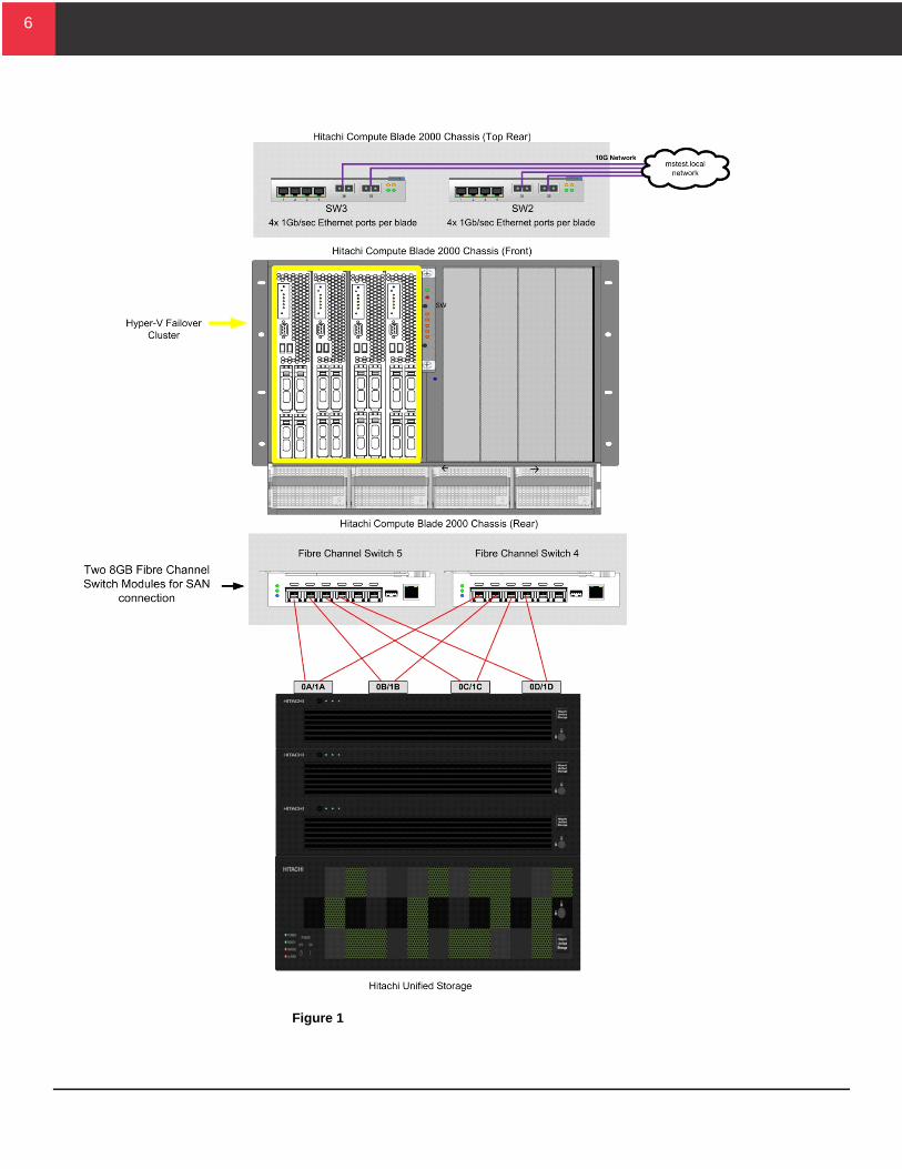
Storage Configuration Best PracticesThese are the best practices to optimize your Hitachi Unified Storage infrastructure for performance, scalability, availability, and ease of management. Figure 1 shows the SAN topology of a Microsoft Hyper-V infrastructure that uses Hitachi Unified Storage with Hitachi Compute Blade 2000.
6
6
Figure 1

7
7
Redundancy A scalable, highly available, and easy-to-manage storage infrastructure requires redundancy at every level.
To take advantage of multipathing support, each Hyper-V host needs redundant paths. This provides protection against HBA hardware failures and Fibre Channel link failures.
Figure 1 shows that when one path is down from a hardware or link failure, another host path still provides access to the storage resources. When connecting Hyper-V hosts in this fashion to a Hitachi Unified Storage system, hosts can use the round robin multipathing algorithm to distribute the I/O load across all available paths.
Hitachi Data Systems recommends a minimum of two HBA ports for redundancy.
Recommendation — Hitachi recommends the use of Hitachi Dynamic Link Manager for path failover and failback for Hyper-V environments. Use the round-robin multipathing policy to take advantage of the Hitachi Unified Storage symmetric active-active front-end ports.
Zone Configuration Zoning divides the physical fabric into logical subsets for enhanced security and data segregation. Incorrect zoning can lead to LU presentation issues to Hyper-V hosts, inconsistent paths, and other problems.
Two types of zones are available, as follows:
Port — This uses a specific physical port on the Fibre Channel switch. Port zones provide better security and can be easier to troubleshoot than WWN zones. This has advantages in a smaller static environment. The disadvantage is the HBA of the Hyper-V host must be connected always to the specified port. Moving an HBA connection results in loss of connectivity and requires rezoning.
WWN — This uses name servers to map the WWN of an HBA to the WWN of a target port. The HBA of the Hyper-V host can be connected to any port on the switch, providing greater flexibility. This has advantages in a larger dynamic environment. The disadvantages are the reduced security and additional complexity when troubleshooting.
Hitachi Data Systems recommends using single initiator zones. These have one initiator (HBA port) with one or more targets in a single zone.
8
8
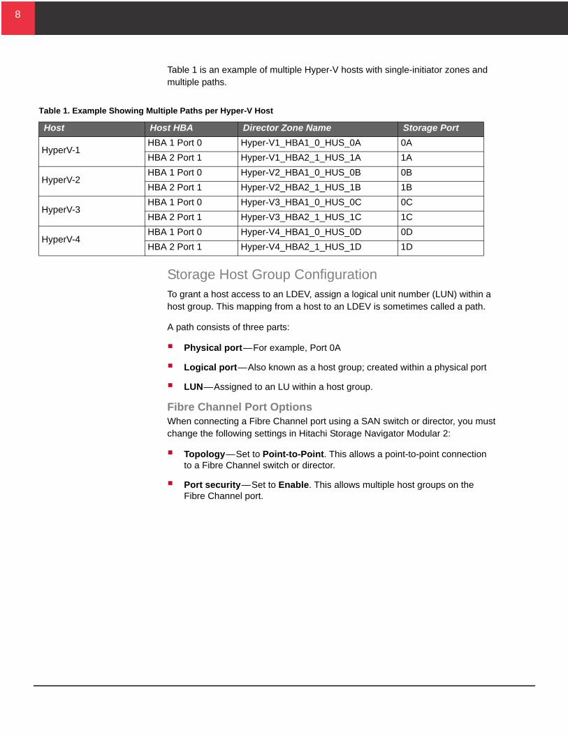
Table 1 is an example of multiple Hyper-V hosts with single-initiator zones and multiple paths.
Table 1. Example Showing Multiple Paths per Hyper-V Host
Host Host HBA Director Zone Name Storage Port
HyperV-1 HBA 1 Port 0 Hyper-V1_HBA1_0_HUS_0A 0A
HBA 2 Port 1 Hyper-V1_HBA2_1_HUS_1A 1A
HyperV-2HBA 1 Port 0 Hyper-V2_HBA1_0_HUS_0B 0B
HBA 2 Port 1 Hyper-V2_HBA2_1_HUS_1B 1B
HyperV-3 HBA 1 Port 0 Hyper-V3_HBA1_0_HUS_0C 0C
HBA 2 Port 1 Hyper-V3_HBA2_1_HUS_1C 1C
HyperV-4HBA 1 Port 0 Hyper-V4_HBA1_0_HUS_0D 0D
HBA 2 Port 1 Hyper-V4_HBA2_1_HUS_1D 1D
Storage Host Group ConfigurationTo grant a host access to an LDEV, assign a logical unit number (LUN) within a host group. This mapping from a host to an LDEV is sometimes called a path.
A path consists of three parts:
Physical port — For example, Port 0A
Logical port — Also known as a host group; created within a physical port
LUN — Assigned to an LU within a host group.
Fibre Channel Port Options When connecting a Fibre Channel port using a SAN switch or director, you must change the following settings in Hitachi Storage Navigator Modular 2:
Topology — Set to Point-to-Point. This allows a point-to-point connection to a Fibre Channel switch or director.
Port security — Set to Enable. This allows multiple host groups on the Fibre Channel port.

9
9
Figure 2 shows the topology settings using Hitachi Storage Navigator Modular 2.
Figure 2
Figure 3 shows the port security setting in Hitachi Storage Navigator Modular 2.
Figure 3
10
10
Recommendation — Hitachi Data Systems recommends applying the same configuration settings to a port in controller 0 to the port in controller 1 in the same location. For example, if you create a host group for a host on Port 0A, also create a host group with the same settings for that host on Port 1A.
Host Group ConsiderationsThese are considerations for defining host groups in a standalone host configuration or a Hyper-V Failover cluster configuration.
One Host Group per Hyper-V Host, Standalone Host Configuration When deploying Hyper-V hosts in a standalone configuration, the WWN of each host can be in its own host group. This approach provides granular control over LUN presentation to Hyper-V hosts.
This is the recommended practice for SAN boot environments, because Hyper-V hosts do not have access to the boot LUNS of other Hyper-V hosts.
However, in a cluster environment, this approach can be an administration challenge. Keeping track of which Hyper-V hosts are in a cluster can be difficult. When multiple Hyper-V hosts need to access the same LDEV for clustering purposes, the LDEV must be added to each host group.
This operation is prone to error, leading to confusion. If you have numerous Hyper-V hosts, this approach can be tedious.
One Host Group per Cluster, Cluster Host Configuration Hyper-V features such as quick migration, live migration, and highly available virtual machines require shared storage across the Hyper-V hosts. Many of these features require presenting the same LUNs to all Hyper-V hosts participating in these cluster functions.
When using Hyper-V hosts with these features, create host groups with clustering in mind. Place all of the WWNs for the clustered Hyper-V hosts in a single host group. This makes sure that when adding LUs to the host group, all Hyper-V hosts see the same LUNs. This creates consistency with LUN presentation across all hosts.

11
11
Host Group Options On Hitachi Unified Storage, create host groups using Hitachi Storage Navigator Modular 2. The host mode is set for the host operating system.
On the Options tab, click Windows from the Platform list for all host groups. See Figure 4 for the host mode setting for Hyper-V environments.
Figure 4
12
12
Hyper-V Storage Deployment OptionsHyper-V storage deployment planning requires considering the following two key factors:
Disk Type
Disk Interface
Disk TypeThe Hyper-V parent partition can present the following two disk types to guest operating systems:
Virtual hard disks (VHD)
Pass-through disks
Virtual Hard DisksThe virtual machine sees a virtual hard disk (VHD) as its own hard disk and uses it to perform storage functions.
A virtual hard disk is a file that exists on a formatted disk on a Hyper-V host with a .vhd extension. The formatted disk that has the VHD file can be SAN attached or local to the Hyper-V server. Each VHD has a maximum capacity of 2 TB.
There are three types of VHD disks available for presentation to the host, as follows:
Fixed VHD — The size of the VHD is fixed. The LU is fully allocated at the time the VHD is defined.
Normally this allows for better performance than dynamic or differencing VHDs. This is the result of less fragmentation, since the VHD is pre-allocated. In addition, the file system of the host partition does not incur the overhead required to extend the VHD file, since all the blocks have been pre-allocated.
A fixed VHD has the potential for wasted or unused disk space. Also, consider that after the VHD is full, any further write operation will fail even though additional free storage might exist somewhere else on the storage system.
Dynamic VHD — The VHD is expanded by Hyper-V, as needed.
Dynamic VHDs occupy less storage as compared to fixed VHDs, but at the cost of slower throughput. The size that the disk can expand to is set at creation. The writes fail when the VHD is fully expanded.
This dynamic feature only applies to expanding the VHD. The VHD does not decrease in size automatically when removing data. However, dynamic VHDs can be compacted to free any unused space using the Hyper-V virtual hard disk manager.

13
13
Differencing VHD — The VHD involves the parent and a child disk.
The parent VHD disk contains the baseline disk image. This has the guest operating systems and, most likely, an application and the data associated with that application.
After configuring the VHD parent disk for the guest, a differencing disk is assigned as part of the VHD as a child to that partition. As the guest operating system executes, it stores any write operations on the child disk.
Differencing VHDs are good for test environments. However, performance can degrade because the majority of I/O must access the parent VHD disk as well as the differencing disk.
Recommendation — Because dynamic and differencing VHDs have more overhead, the recommended practice is to use fixed VHDs in most circumstances. For heavy application workloads, such as Microsoft Exchange or a SQL database, create multiple fixed VHDs and isolate applications files, such as database and logs, on their own VHDs.
Pass-through DisksA Hyper-V pass-through disk is a physical disk or LU that is mapped or presented directly to the guest operating system. Hyper-V pass-through disks normally provide better performance than VHD disks.
After a pass-through disk is visible to the host partition but offline, you can make it available to the virtual machine partition using Hyper-V Manager. Pass-through disks have the following characteristics:
Must be in the offline state from the Hyper-V host perspective, except in the case of clustered or highly available virtual machines
Presented as a raw disk to the parent partition
Cannot be dynamically expanded
Does not allow the capability to take snapshots or utilize differencing disks
Recommendation — Pass-through disks are best suited for large datasets (larger than 500 GB) and situations with extreme I/O requirements. Hitachi Data Systems recommends the use of pass-through disks for virtual machines when virtual disks require more than 2 TB of storage.

14
14
Disk InterfaceMicrosoft Hyper-V supports IDE and SCSI controllers for VHD and pass-through disks. The type of controller you select is the disk interface that the guest operating system sees. The disk interface is completely independent of the physical storage system.
Table 2 summarizes disk interface considerations and restrictions.
Table 2. Disk Interface Considerations and Restrictions
Disk Interface Considerations Restrictions
IDE
All virtual machine partitions must boot from an IDE device
None
A maximum of four IDE devices are available for each virtual machine.
A maximum of one device per IDE controller for a maximum of four devices per virtual machine
Virtual DVD drives can only be created as an IDE device
None
SCSI
Best choice for all volumes based on I/O performance
None
Requires that Integrations services be installed on the virtual machine
Guest operating system specific
Can define a maximum of four SCSI controllers per virtual machine
A maximum of 64 devices per SCSI controller for a maximum of 256 devices per virtual machine
Recommendation — For best overall performance, use SCSI devices to present disks to the virtual machines.

15
15
Hyper-V Storage ProvisioningMicrosoft Hyper-V supports the use of the following types of storage:
Attached directly to the server (DAS)
Shared storage using Fibre Channel and iSCSI
To scale the Hyper-V environment, Microsoft highly recommends the use of external shared storage. Advanced features of Microsoft Hyper-V, such as quick migration and live migration, require the use of shared storage.
Microsoft Hyper-V supports three different volume types when provisioning LUNs to a Hyper-V host or a Hyper-V failover cluster. These three types are:
Standard Volumes — A standard volume is a physical disk that is connected and dedicated to the Hyper-V host parent partition. A standard volume can be provisioned from either DAS or provisioned as a LUN on Hitachi Unified Storage.
Standard Cluster Volumes — A standard cluster volume is a physical disk connected to multiple Hyper-V hosts that have been configured as a Windows Hyper-V failover cluster. In this configuration, only one Hyper-V host within the cluster has read/write access to the volume and owns that volume.
You may only create a standard cluster volume on shared storage to which all nodes in the failover cluster are connected.
When deploying standard cluster volumes, Microsoft recommends a one-to-one mapping of virtual machines to LUNs. If multiple virtual machines are present on a single standard cluster volume, the virtual machines cannot migrate the individual virtual machines quickly. Instead, the virtual machines are migrated as a group. This means a temporary outage for all virtual machines allocated on a standard cluster volume.
Cluster Shared Volumes — A cluster shared volume (CSV) is a physical disk connected to a Hyper-V failover cluster and shared between the nodes in the cluster. A CSV is a distributed access file system that is optimized for Hyper-V. It uses NTFS.
CSVs enable all nodes in the cluster to access CSV volumes or LUNs concurrently.
You may only create a CSV on shared storage to which all nodes in the failover cluster are connected.

16
16
When using CSVs with Microsoft Windows Server 2008 R2, Hyper-V provides the following advantages in a failover cluster:
Simplify storage management. CSV volumes require fewer LUs to host the same number of virtual machines.
Eliminate the drive letter restriction. CSV volumes do not require a drive letter.
Provide individual failover of virtual machines. This is true even when multiple virtual machines share the same LU.
Remember these storage planning considerations when using CSV volumes in a Hyper-V failover cluster:
Use hardware-based storage replication copies at the LU level. The replicated CSV LU likely contains VHDs from multiple virtual machines. If you are using the replicated CSV in a high availability or disaster recovery solution to support quick migration or live migration, all virtual machines in the CSV LU are migrated.
To provide for ease of management and scalability, deploy CSVs using Hitachi Dynamic Provisioning on Hitachi Unified Storage. Typically, CSV LUs contain multiple VHD files for the virtual machines. The LUs deployed are typically larger than LUs deployed on standard Windows volumes. This makes using pools created with Hitachi Dynamic Provisioning a good choice. As the demand for additional virtual machines grows, you can add additional capacity and I/O processing power dynamically to the environment.
Understand the workloads of individual virtual machines when hosting them on a CSV LU. Verify that the dynamic provisioning pool on Hitachi Unified Storage that hosts the CSV LU can support the aggregate workload of all virtual machines that are contained within the CSV LU.
The failover cluster console enables a standard LUN as a CSV. The Hyper-V node where the LUN was first enabled as a CSV becomes the owner node or coordinator node.
All nodes in the failover cluster can concurrently access the CSV. However, the following is true:
CSV non-owner nodes must send all metadata changes to the owner node to perform the updates. Metadata updates are changes to the properties or size of a file on the CSV.
All other direct I/O operations can be performed on the CSV by any node in the cluster.
Figure 5 shows that Virtual Machine 2 has direct I/O access over a Fibre Channel network to its VHD on the CSV, even though Cluster Node A owns the CSV volume. Metadata updates are sent over the network to Cluster Node A.

17
17
Figure 5
I/O RedirectionCSV provides improved fault tolerance with dynamic I/O redirection. This allows storage and network I/O to be redirected within the failover cluster based on available connections. This allows communication to continue to CSV volumes in the event of a Fibre Channel path failure. It routes the I/O over the network to a server that still has a fibre connection to the shared CSV.
When storage I/O is redirected over the network, performance of the Hyper-V cluster nodes and virtual machines may be affected. This is true especially when the bandwidth of the IP network is less that the bandwidth of the failed path.
To minimize the chance of I/O redirection, follow these recommended practices:
Implement Hitachi Dynamic Link Manager or Microsoft MPIO on all nodes in the cluster. This lowers the chances of I/O redirection occurring.
Dedicate a separate, physical 1 GB network adapter only for CSV traffic. If the environment consists of servers with large memory sizes (64 GB or larger), a large number of CSVs, or extensive use of live migration, consider the use of 10 GB network adapters for CSV traffic.
18
18
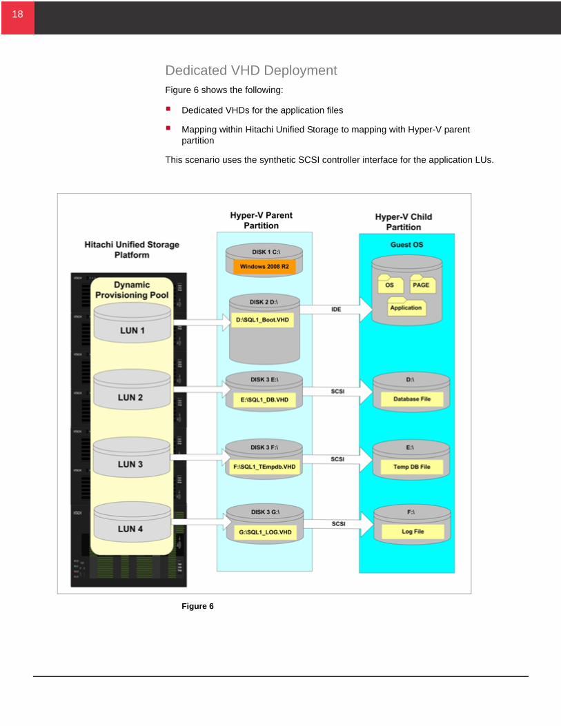
Dedicated VHD DeploymentFigure 6 shows the following:
Dedicated VHDs for the application files
Mapping within Hitachi Unified Storage to mapping with Hyper-V parent partition
This scenario uses the synthetic SCSI controller interface for the application LUs.
Figure 6

19
19
Key Considerations For better performance and easier management of child partitions,
assign a single set of LUs.
To enable quick migration or live migration of a single child partition, deploy dedicated VHDs.
To enable moving multiple child partitions together using quick migration or live migration, deploy shared VHDs.
To achieve good performance for heavy I/O applications, deploy dedicated VHDs.
Shared VHD DeploymentThis scenario utilizes a shared VHD disk hosting multiple child partitions.
Figure 7 shows Hitachi Unified Storage hosting the following:
Microsoft Exchange and SQL Server child partitions sharing a VHD disk
Microsoft SharePoint and Microsoft BizTalk child partitions sharing a VHD disk

20
20
Figure 7

21
21
Key Considerations Understand individual child partition workloads when hosting them
on a single shared VHD. It is critical to verify that the dynamic provisioning pool on Hitachi Unified Storage that hosts the VHD LU supports the aggregate workloads of the child partitions.
If using quick migration or live migration to move a child partition, all child partitions hosted within a shared VHD move together. This is true whether the outage is due to automated recovery from a problem with the child partition or because of a planned outage.
Pass-through Disk Deployment This scenario uses pass-through disks instead of VHD disks. This still requires a dedicated VHD LU to host virtual machine configuration files. Do not share this VHD LU with other child partitions on the Hyper-V host.
Figure 8 shows the following:
Virtual machine configuration files, guest OS binaries, the page file and SQL Server application libraries are placed on the VHD LU
Application files are deployed as pass-through disks

22
22
Figure 8

23
23
Key considerations For higher throughput, deploy pass-through disks. This normally
happens because pass-through disks involve only the file system of the guest partition. Microsoft states that, with Hyper-V R2, there is 5 percent performance improvement using pass-through disks versus VHD disks.
To achieve an easier migration path, deploy pass-through disks. This can provide an easier migration path because the LUs used by a physical machine on a SAN with pass-through disks can be moved easily to a Hyper-V environment. This scenario is appropriate especially for partially virtualized environments.
To support multi-terabyte LUs, deploy pass-through disks. This supports multi-terabyte LUs because pass-through disks are not limited in size.
Cluster Shared Volume DeploymentCluster shared volumes (CSVs) provide the most flexibility for deploying virtual machines in a failover cluster configuration. With CSV, a few large LUs, each with a CSV, can be created for many or all virtual machines and their associated configuration files.
This method of storage allocation reduces wasted disk space. The virtual machines share a larger capacity pool.
Figure 9 shows presenting multiple CSVs to the Hyper-V parent partition, which is a Hyper-V failover cluster node. The CSVs host multiple virtual machines with their associated operating systems and application files.

24
24
Figure 9
Key Considerations Live migration with CSVs provides a performance advantage over
standard cluster volumes. Standard cluster volumes have to be unmounted and remounted as part of the live migration process. Live migration with CSVs reduces the brown-out period at the end of the live migration.
With deployment of CSVs, Microsoft no longer restricts or recommends deployment of one virtual machine per LUN.

25
25
iSCSI Storage DeploymentThe Hyper-V architecture offers two methods for deploying iSCSI storage disks to the child partition on Hitachi Unified Storage:
Direct connection
Dual connection
Configure iSCSI ports to the Hyper-V host to access LUs on Hitachi Unified Storage.
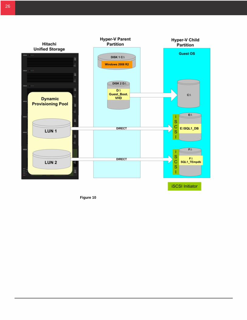
Direct ConnectionOne iSCSI deployment method is a direct connection to Hitachi Unified Storage from the child partition. The child partition must do the following:
Support the Microsoft iSCSI software initiator
Have the correct device driver
Figure 10 shows a direct connection configuration. The child partition boots from the VHD on the Hyper-V parent partition. The storage system has no external LU to contain the configuration files, OS binaries or application libraries.
26
26
Figure 10

27
27
Key Considerations For increased availability due to dynamic addition of LUs to the child
partition, use the direct connection configuration.
For simpler physical to virtual conversions, use the iSCSI direct connection configuration. Do this when reconfiguration of the iSCSI initiator and targets is not required.
Use dedicated NICs for iSCSI traffic. Do not share the iSCSI traffic with other network traffic. Dedicated NICs provide greater performance and throughput. Other network traffic does not interfere with the storage traffic on the iSCSI NICs.
For easier movement of child partitions between Hyper-V hosts, use the direct connection configuration. Do this when no changes are required to the Hitachi Unified Storage system.
The direct connection configuration does not support snapshots using Microsoft® Volume Shadow Copy Service hardware provider for Hitachi Storage (VSS).
Dual ConnectionAnother iSCSI deployment option is to connect the child partition to the Hyper-V parent partition and the child partition. Implementing this combination of connections provides more flexibility for configuring iSCSI connections to meet the storage needs of the child partition.
Figure 11 shows the dual connection deployment option.

28
28
Figure 11
Key Considerations For better network performance, when a child partition with iSCSI-
attached storage is executing in the parent partition, use the dual connection configuration. The NIC in the parent partition communicates directly with the iSCSI storage system. In addition, this leverages jumbo frame support on the physical NIC in the Hyper-V parent partition.
For better server performance from a reduced CPU load, leverage TCP offload engine (TOE) NICs and TCP offload cards, if possible.
Use dedicated NICs for iSCSI traffic. Do not share iSCSI traffic with other network traffic. Dedicated NICs provide greater performance and throughput. Other network traffic does not interfere with the storage traffic on the iSCSI NICs.
To present multiple LUs to the child partition over a single iSCSI interface, use the dual connection configuration.

29
29
The dual connection configuration does not support dynamic addition of disks to the child partition.

30
30
Storage Sizing Capacity and performance of storage cannot be considered independently. Performance and capacity always depend on each other. That is why it is very difficult or impossible in real-life scenarios to provide recommended practices for the best LU size, the number of child partition that can run on a single VHD, and so on, without knowing capacity and performance requirements. Consider these factors when planning storage provisioning for a Hyper-V environment.
Selecting Child Partition StorageSelect the type of storage deployed for the guest operating system correctly that is to be virtualized under Hyper-V. Consider whether VHD, CSV, or pass-through disks are appropriate. The following questions can help you make this determination:
Is the child partition’s I/O workload heavy, medium, or light?
If the child partition has a light workload, you might be able to place all the storage requirements on one VHD LU.
If the child partition is hosting an application such as Microsoft SQL Server or Microsoft Exchange, allocate files that are accessed heavily, such as log and database files, to individual VHD LUs.
Attach each individual LU to its own synthetic controller.
What is the maximum size LU required to support the child partition?
If the maximum LU is greater that 2040 GB, do one of the following:
Split the data
Utilize CSVs or pass-through disks.
This is because the VHD LU size limitation of 2040 GB.

31
31
Determine the LU Size When determining the right LU size, consider the factors listed in Table 3. These factors are especially important from a storage system perspective. Always consider the following:
Capacity of the individual child partition
Performance requirements, including basic virtual disk requirements, virtual machine page space, and spare capacity for virtual machine snapshots
Table 3. LU Sizing Factors
Factor Comment
Guest base operating system size
The guest operating resides on the boot device of the child partition.
Guest page file Size Recommended size is 1.5 times the amount of RAM allocated to the child partition.
Virtual machine files Define the size as the memory size of the child partition plus 200 MB.
Application data required by the guest machine
This is the storage required by the application files such as database and logs.
Modular volume migration Smaller LUs can be migrated using Hitachi Modular Storage Migration to a broader range of possible target RAID groups.
Data replication Using more, but smaller LUs, offers better flexibility and granularity when doing replication for the following situations:
Within a storage system using Hitachi ShadowImage® Replication or Hitachi Copy-on-Write Snapshot
Across storage systems using Hitachi TrueCopy® or Hitachi TrueCopy® Extended Distance

32
32
Number of Virtual Machines per VHD LU or CSV LUWhen using Hitachi Dynamic Provisioning for hosting guest virtual machines, a dynamic provisioning pool hosts the guest virtual machine VHD LUs. As the requirement for the number of guest virtual machines increases, you can add additional capacity to the dynamic provisioning pools dynamically.
Adding additional RAID groups to the dynamic provisioning pool does the following:
Increases the storage capacity available for deploying guest virtual machines
Provides additional I/O processing capabilities resulting from to the increased number of spindles in the pool
LUs from Hitachi Unified Storage are allocated to the Hyper-V hosts. They are formatted as volumes in which virtual hard disks or VHDs can be created.
The VHDs are presented to the Microsoft Windows 2008 operating system, partitioned, and used as containers to house the virtual machine operating system and paging files. Based on the I/O and capacity requirements of the virtual machine, application files can exist within this VHD or they can be placed on separate VHD LUs based on application I/O and capacity requirements.
If a virtual machine hosts an application with a large number of LUs or very performance-sensitive LUs such as Exchange or SQL databases, Hitachi Data Systems recommends using separate VHDs or pass-through disks.
If you decide to run multiple virtual machines on a single VHD LU, remember that the number of child partitions that can run simultaneously on a VHD LU depends on the aggregated capacity and performance requirements of the virtual machines.
Because all LUs on a particular dynamic provisioning pool share the performance and capacity offered by the pool, Hitachi Data Systems recommends dedicating dynamic provisioning pools to a Hyper-V host or a group of Hyper-V hosts (for example, a Hype-V failover cluster). Do not assign LUs from the same RAID group or dynamic provisioning pool to other non-Hyper-V hosts. This prevents the Hyper-V I/O from affecting or being affected by other applications and LUs on the same dynamic provisioning pool. In addition, it makes management simpler.

33
33
Follow these recommended practices:
Create and dedicate dynamic provisioning pools to your Hyper-V hosts.
Always present LUs with the same host LUN (H-LUN) if they are shared with multiple Hyper-V hosts. H-LUNs are the logical host LU within the Hitachi Unified Storage that it tied to the physical LU on the storage system. In a failover cluster, each all H-LUN nodes in the cluster must point to the same physical LU.
Create VHDs on the LUs as needed.
Monitor and measure the capacity and performance usage of the dynamic provisioning pool with Hitachi Tuning Manager and Hitachi Performance Manager.
Monitoring and measuring the capacity and performance usage of the RAID group or dynamic provisioning pool results in one the following cases:
If all of the capacity offered by the dynamic provisioning pool is used but performance of the pool is still good, add RAID groups to gain more capacity.
If all of the performance offered by the dynamic provisioning pool is used but capacity is still available, do not use the remaining capacity by creating more LUs. This leads to even more competition on the pool and affects the overall performance for the virtual machines residing on this dynamic provisioning pool.
In this case, leave the capacity unused and add more RAID groups and, as a result, more performance resources. In a real environment, it is not possible to use 100 percent of capacity and performance of a dynamic provisioning pool. However, the usage ratio can be optimized by actively monitoring the systems and moving data to the appropriate storage tier as needed using Hitachi Modular Volume Migration or Hitachi Tiered Storage Manager. An automated solution using these applications from Hitachi Storage Command Suite helps to reduce the administrative overhead and optimize storage utilization.

34
34
Hyper-V Protection StrategiesA successful Hyper-V deployment requires careful consideration of protection strategies for backups, disaster recovery, and quick migration.
BackupsRegularly scheduled backups of the Hyper-V servers and the data that resides on the child partitions under Hyper-V are an important part of any Hyper-V protection plan. With Hyper-V, the backup and protection process involves the Hyper-V parent partition and the child partitions that execute under Hyper-V, along with the applications that reside within the child partition.
When protecting child partitions, you have the following two protection strategies are available:
Create application-aware backups of each child partition, as if they are hosted on individual physical servers
Backup the parent partition at a point in time, which then creates a backup of the child partitions that were executing on the parent partition.
When backing up the parent partition, keep the state of the physical server in mind. For example, if a backup of the parent partition is created while two child partitions are executing applications, the backup is a point-in-time copy of the parent and the child partitions.
Any applications that are executing in the child partitions are unaware that a backup occurred. This means that applications such as Microsoft Exchange or SQL Server cannot freeze writes to the databases, set the appropriate application checkpoints, or flush the transaction logs.
Recommended practice is to perform application-aware backups in the child partitions.

35
35
Protection for Cluster Shared VolumesA standard CSV deployment places the VHDs for the virtual machines on a CSV with the virtual machines distributed across all the nodes in the cluster. Each virtual machine has direct I/O access to its respective VHD on the CSV.
Figure 12 shows Virtual Machine 2 has direct I/O access over a Fibre Channel network to its VHD on the CSV, even though Cluster Node A owns the CSV volume.
Figure 12

36
36
When you initiate a backup for Virtual Machine 2 with Data Protection Manager 2010 (DPM), CSV ownership moves to Cluster Node B. This causes routing all Fibre Channel I/O for VM1 over the network through the CSV filter on Node B. This affects the performance of Virtual Machine 1 because now all I/O is redirected over the network, as shown in Figure 13.
Figure 13
Recommendation — To reduce the negative performance effect of redirected I/O on Virtual Machine 1, use Microsoft® Volume Shadow Copy Service hardware provider for Hitachi Storage (VSS). This allows the CSV to resume direct I/O as soon as the hardware snapshot is taken. Use of VSS shortens the duration of the redirected I/O to approximately two minutes in most cases.
If you use the software provider instead of the hardware provider to create backups, the CSV is in redirected I/O mode for all the virtual machines on the CSV for the duration of the backup. This backup duration depends on the size of the VHD being backed up. The time can be significant. During the duration of redirected I/O mode, the performance of other virtual machines on the CSV is reduced.

37
37
Storage ReplicationAnother important part of your protection strategy is storage replication. Hitachi Unified Storage has built-in storage replication features, such as Hitachi ShadowImage® Replication and Hitachi Copy-on-Write Snapshot. These can provide rapid recovery and backup in a Hyper-V environment.
When placing more and more child partitions on a physical Hyper-V server, the resources within the Hyper-V server might become constrained. This affects the backup window. By using solutions such as ShadowImage Replication on Hitachi Unified Storage, backups can created with little effect on the Hyper-V host.
These ShadowImage Replication copies can be backed up to tape or disk. This means that child partitions hosted by Hyper-V can be recovered very quickly.
Hyper-V Quick Migration and Live MigrationHyper-V quick migration provides a solution for planned and unplanned downtime. Planned downtime allows for the quick movement of virtualized workloads to service the underlying physical hardware. This is the most common scenario when considering the use of quick migration or live migration.
Quick migration requires the use of failover clustering. The storage must be shared between the physical Hyper-V nodes. For a planned migration, quick migration does the following:
Saves the state of a running child partition (memory of original server to the disk and shared storage)
Moves the storage connectivity from one physical server to another
Restores the partition to the second server (the disk and shared storage to memory on the new server)
Live migration also requires the use of failover clustering. For a planned migration, live migration copies the memory contents of the child partition being migrated. It results in no outage to the child partition. Live migration does not have to move the storage connectivity for the virtual machine, resulting in much faster migration times.

38
38
Consider the following when configuring disks for quick and live migration:
VHD Disks
The recommended practice is to use one child partition per LU.
The ability exists to provision more than one child partition per LU. However, remember all child partitions on the VHD LU failover as a unit.
CSV Disks
When hosting multiple child partitions on a CSV LU, quick migration allows the movement of a single child partition. This removes the restriction of one child partition per LU.
Pass-through Disks
This requires storing the virtual machine configuration file on a separate LU from the LUs that host the data files. Normally this is a VHD LU that is presented to the Hyper-V parent partition.
Do not allow any other child partitions to share the virtual machine configuration file or VHD LU. Sharing the virtual machine configuration file or VHD LU among child partitions can lead to corruption of data.
This alleviates possible issue of the 26-drive letter limitation for a child partition with a large number of LUs. Pass-through disks do not require a drive letter because they are offline to the parent.
Hitachi Storage ClusterIntegrating Hyper-V with Hitachi Unified Storage replication solutions provides high availability for disaster recovery scenarios. Leverage quick migration or live migration in Hyper-V to allow for the planned and unplanned recovery of child partitions under Hyper-V.
Disaster recovery solutions consist of remote LU replication between two sites. The automated failover of child partition resources to the secondary site happens in the event that the main site goes down or is otherwise unavailable.
Hitachi Storage Cluster for Microsoft® Hyper-V™ and the storage system controllers handle data replication and control. This has little effect on the applications running in the child partition. It is fully automated. The use of consistency groups and time-stamped writes verifies database integrity.
Child partitions run as clusters resources within the Hyper-V cluster. If a node within the cluster that is hosting the child partition fails, the child partition automatically fails over to an available node. The child partitions can be moved quickly between cluster nodes. This allows for planned and unplanned outages. Storage Cluster automatically brings the replicated LUs and the child partition online.

39
39
Figure 14 shows how multiple child partitions and their associated applications can be made highly available using Storage Cluster.
Figure 14
Performance MonitoringA complete, end-to-end picture of your Hyper-V Server environment and continual monitoring of capacity and performance are key components of a sound Hyper-V management strategy.
The principles of analyzing the performance of a guest partition installed under Hyper-V are the same as analyzing the performance of an operating system installed on a physical machine. Use tools such as Hitachi Performance Monitor and Microsoft Windows Performance Monitor (PerfMon) to monitor the following:
Servers
Operating systems
Child partition application instances
Databases
Database applications
Storage and IP networks
Hitachi Unified Storage

40
40
While PerfMon provides good overall I/O information about the Hyper-V parent and the guests under the Hyper-V parent, it cannot identify all possible bottlenecks in an environment.
For a better overall understanding of the I/O profile of a Hyper-V parent and its guest partitions, also monitor the performance of the storage system with Hitachi Performance Monitor. Combining data from these two performance-monitoring tools provides a more complete picture of the Hyper-V environment.
PerfMon is monitors each server and cannot provide a holistic view of the storage system. For a complete view, use PerfMon to monitor all servers that are sharing a RAID group.
Hitachi Performance MonitorHitachi Performance Monitor is a controller-based software application, enabled through Hitachi Storage Navigator Modular 2 software.
You can measure utilization rates of disk subsystem resources, such as load on disks and ports, with Hitachi Performance Monitor. When a problem such as slow response occurs in a host, use Hitachi Performance Monitor feature to determine quickly if the disk subsystem is the source of the problem.
Performance Monitor watches the performance of RAID groups, logical units and other elements of the disk subsystem. It tracks utilization rates of resources, such as hard disk drives and processors.
It displays information using line graphs in the Performance Monitor window. You can save the information in comma-separated value (.csv) files.
Hitachi Tuning Manager Hitachi Tuning Manager enables you to proactively monitor, manage, and plan the performance and capacity for the Hitachi modular storage that is attached to your Hyper-V servers.
Tuning Manager consolidates statistical performance data from the entire storage path. This includes collecting performance and capacity data from the following to provide a complete performance picture:
Operating system
Switch ports
Storage ports on the storage system
RAID groups
LUs
It provides historical, current, and forecast views of these metrics.
For more information about Hitachi Tuning Manager software, see the Hitachi Data Systems support portal.

41
41
Windows Performance MonitorPerfmon is a Microsoft Windows-based application that allows you to monitor the performance of a system using counters or graphs, in logs or as alerts on the local or remote host.
The best indicator of disk performance on a Hyper-V parent operating system is obtained by using the \Logical Disk(*)\Avg. sec/Read and \Logical Disk(*)\Avg. sec/Write performance monitor counters. These performance monitor counters measure the latency time that read and write operations take to respond to the operating system. In general, average disk latency response times greater than 20 msec on a disk are cause for concern.
While it is possible to collect Perfmon counters from each virtual machine running on a Hyper-V host, using this method is very tedious. A better method is to collect Hyper-V counters on the host, such as those in the Hyper-V Virtual Storage Device category, to avoid having to compile results from multiple virtual machines.
Also collect data from the Cluster Shared Volumes category to determine usage and performance of CSV LUNS. Compare the counter from the Hyper-V Virtual Storage Device and Cluster Shared Volumes categories with the Logical Disk category of the Hyper-V host to see the difference between the virtual machines and what the host actually sends to disk.
For more information about monitoring Hyper-V related counters, see Measuring Performance on Hyper-V on TechNet.
For More Information
Hitachi Data Systems Global Services offers experienced storage consultants, proven methodologies and a comprehensive services portfolio to assist you in implementing Hitachi products and solutions in your environment. For more information, see the Hitachi Data Systems Global Services website.Live and recorded product demonstrations are available for many Hitachi products. To schedule a live demonstration, contact a sales representative. To view a recorded demonstration, see the Hitachi Data Systems Corporate Resources website. Click the Product Demos tab for a list of available recorded demonstrations.
Hitachi Data Systems Academy provides best-in-class training on Hitachi products, technology, solutions and certifications. Hitachi Data Systems Academy delivers on-demand web-based training (WBT), classroom-based instructor-led training (ILT) and virtual instructor-led training (vILT) courses. For more information, see the Hitachi Data Systems Services: Education website.
For more information about Hitachi products and services, contact your sales representative or channel partner or visit the Hitachi Data Systems website.

Corporate Headquarters750 Central Expressway, Santa Clara, California 95050-2627 USAwww.HDS.com
Regional Contact InformationAmericas: +1 408 970 1000 or [email protected], Middle East and Africa: +44 (0) 1753 618000 or [email protected] Asia-Pacific: +852 3189 7900 or [email protected] is a registered trademark of Hitachi, Ltd., in the United States and other countries. Hitachi Data Systems is a registered trademark and service mark of Hitachi, Ltd., in the United States and other countries. All other trademarks, service marks, and company names in this document or website are properties of their respective owners.
Notice: This document is for informational purposes only, and does not set forth any warranty, expressed or implied, concerning any equipment or service offered or to be offered by Hitachi Data Systems Corporation.
© Hitachi Data Systems Corporation 2012. All Rights Reserved. AS-137-00 April 2012