mindstorm - diva portalhh.diva-portal.org/smash/get/diva2:421137/fulltext01.pdf · designed for the...
TRANSCRIPT

Technical report, June 2011
MINDSTORM
Bachelor’s Thesis in Computer Engineering
Jiang Chun hui & Mao Yu jiao
School of Information Science, Computer and Electrical Engineering
Halmstad University

MINDSTORM
Bachelor Thesis in
Computer Engineering
School of Information Science, Electrical Engineering
Halmstad University
Box 823, S-301 18 Halmstad, Sweden
June 2011

I
Acknowledgement First of all we really appreciate the great help from our supervisor Tommy
Salomonsson. He not only gives us the professional advice on the project but also gives us confidence and courage to overcome difficulties. With his help we have enthusiasm to finish the project.
Furthermore we are grateful to Professor Ulf Holmberg. He spends his spare time to help us develop the central controller in part of the project which helps us get better result.
And also thanks to Kenneth Nilsson who guides us during the whole process. Finally we won’t forget the support from our families.

II
Preface
Group: Jiang Chun hui & Mao Yu jiao
University: Halmstad University, Sweden
Degree Program: Computer Science and Engineering
Title of Thesis: Mindstorm
Academic Supervisor: Tommy Salomonsson

III
Abstract Since the mindstorm kit is widely used by students and beginners, demand of a
commercial-free integrated embedded working environment turns up. With its help the limitation on working place and complexity of programming can be reduced. The aim of this project is to use a combination of commercial-free softwares as an embedded working environment. The environment can deal with the mindstorm kit applications directly. In order to show the successful generation of the commercial-free software's project an inverted pendulum is set up. Open source firmware of NXT-G is used to provide basic interface for invoking the functions in NXT master brick. Accelerometer is working as the sensor. The main dynamic controller falls on the PD controller to keep inverted pendulum in vertical and static state. As a result the inverted pendulum programmed in this working environment can keep balance for a couple of seconds.

IV
Contents Acknowledgement....................................................................................................................... I
Preface ........................................................................................................................................... II
Abstract........................................................................................................................................III
Contents .......................................................................................................................................IV
List of figures ..............................................................................................................................V
1. INTRODUCTION..................................................................................................................1
1.1 Background ..................................................................................................1 1.2 Thesis objective ............................................................................................1 1.3 Related works ...............................................................................................1
2. METHOD .................................................................................................................................3
2.1 Eclipse integrated development environment and the tools for AT91SAM7S cross development..........................................................................3
2.1.1 Eclipse and the tools ...............................................................................3 2.1.2 Create the binary file...............................................................................3 2.1.3 File transmission .....................................................................................4 2.1.4 Debugging...............................................................................................4
2.2 Operating system ..........................................................................................5 2.3 I2C Protocol..................................................................................................6 2.4 Accelerometer...............................................................................................7 2.5 Filter ..............................................................................................................9 2.6 PID controller.............................................................................................10
2.6.1 PID controller........................................................................................10 2.6.2 PID controller with filter.......................................................................12
2.7 Build the model ..........................................................................................13 3. SOLUTION...........................................................................................................................15
3.1 Generate Eclipse project ...........................................................................15 3.1.1 Solder the physical media for J-TAG interface.....................................15 3.1.2 Merge,Compile and link all the files into binary file............................16
3.2 Keep Balance ..............................................................................................17 3.2.1 Control the motor..................................................................................17 3.2.2 Screen....................................................................................................18 3.2.3 Read sensor value .................................................................................19 3.2.4 Get tilt angle..........................................................................................21 3.2.5 Application of PID controller formula..................................................21 3.2.6 NXT-G project ......................................................................................25 3.2.7 RobotC project ......................................................................................27
4. Result & Discussion ............................................................................................................28
5. Conclusion .............................................................................................................................30
Reference ....................................................................................................................................31
Formula list................................................................................................................................32
Table List ....................................................................................................................................33
Appendix: Makefile source data .........................................................................................33

V
List of figures Figure 1: Flow chart of the GNU Make utility Figure 2: Working mechanism of Eclipse targeting the hardware J-TAG pins through OpenOCD and GDB Figure 3: Sample I2C Implementation. Figure 4: I2C Communication Protocol Figure 5: The gravity acceleration components' generating. Figure 6: Diagram of the PID controller in this project Figure 7: Working mechanism of parameter N in a low pass filter Figure 8: Structural representation of the lateral section. Figure 9: ARM J-TAG interface Figure 10: J17 pin on the board Figure 11: Wires for the J-TAG connector Figure 12: Put digit Figure 13: Screen Display Figure 14: NXT-G working environment Figure 15: RobotC working environment Figure 16: Balance of the inverted pendulum

1
1. INTRODUCTION
1.1 Background
Since the application of robots is used in more and more fields, robots gradually come into ordinary people’s eye. Among those products Lego Mindstorm education robot kit is popular among classes and homes. Halmstad University wants to introduce the mindstorm kit to the course Autonomous Mechatronical System. Though some people prefer to programme the robots with the graphic user interface working environment provided by the Lego Company called “NXT-G”, due to the limitation of graphic manipulation and module-processing speed, some operations are hard to implement or become more time-consuming. These drawbacks can be overcome with mainstream embedded programming software. In addition the request of the programming language in the course is ANSI C. However this change may cause the high payment for the software or accessories designed for the mindstorm kit. In this way students or self learners will not have a flexible choice for the working place. Thus it is better to find an embedded system working environment with standard programming language C which can be set up directly to work with mindstorm kit. The idea falls on the Eclipse open source software and the J-TAG connector arm-usb-tiny, a low cost arm-usb J-TAG.
1.2 Thesis objective
The thesis objective is to set up the Eclipse software together with yagarto tool package as the embedded working environment. The working environment can work directly with the mindstorm kit.
Depending on this environment a demonstrator – an inverted pendulum is built to
show the usability of this environment. Through this project an estimate on the performances of this working environment is listed out.
1.3 Related works
Since the Lego Company released the uncompiled source code of the NXT-G’s operating system, some groups of people started to change and compile the codes to

2
create projects of the mindstorm robots even the software for programming mindstorm kits. They created the customized operating system working for specific software in order to simplify the procedures of programming, in the meanwhile, preserve the high performance of the codes. Here goes some of the sophisticated projects: � RobotC
It is programming-language based on C. The firmware for RobotC has been modified and optimized by their group. It raises the speed of running programs and compresses the application files [1]. RobotC requires this firmware downloaded from the RobotC working environment in order to run. It is commercial. � leJOS NXJ
LeJOS NXJ is an open source project which uses custom firmware developed by the leJOS team. It is language based on Java [2]. � nxtOSEK
This project works with Eclipse partly and also it uses programming language C. Nevertheless it needs customized firmware and some auxiliary programs to set up the function for compiling and communication [3].

3
2. METHOD
2.1 Eclipse integrated development environment and the tools for
AT91SAM7S cross development
2.1.1 Eclipse and the tools
There are two processors in the mindstorm master brick. Most work is dealed with the Atmel 32-bit ARM sam7-S256. Another co processor is Atmel 8-bit AVR processor [4]. The AVR processor assists the ARM processor. It helps with the power management creating PWM output signals for three motors and performing A/D conversion for the input ports. ARM processor is the one that controls most devices and the data communication between them. To establish the connection between the pc and the ARM processor J-TAG interface is one choice which is used directly for chip testing and debugging. To work with an ANSI C language project programmers have a wide range of choices of software. Among these ones Eclipse comes up for its complete integrated development environment, different choices of powerful plugins, open source community and not-for-profit. Another essential tool is the J-TAG connector which provides the physical communication. Other important auxiliary program tools are provided by the integrated ARM tool chain package called Yagarto. It includes Binutils, Newlib, GCC compiler and the GDB debugger [5]. The set of all those makes an embedded programming and debugging environment with clear and simple interface.
2.1.2 Create the binary file
Binary file is a kind of file containing information in a format only certain processor knows [6]. The information in it is gathered from essential c files and assembly files to which have already been inserted the targeting memory address by the linker files. So the binary file contains machine language instructions to be executed by the processor.
In Eclipse all the procedures above can be done with the help of the GNU tool
chain for ARM in the yagarto package and done by just clicking one button in Eclipse user interface after configuration. Eclipse uses the “GNU Make utility” to organize and automatically do those. “Make” function follows instructions in the makefile
4
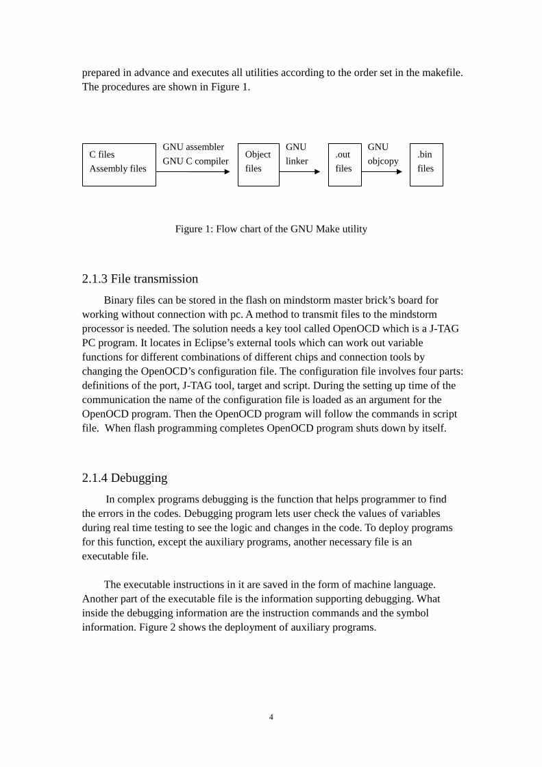
prepared in advance and executes all utilities according to the order set in the makefile. The procedures are shown in Figure 1.
Figure 1: Flow chart of the GNU Make utility
2.1.3 File transmission
Binary files can be stored in the flash on mindstorm master brick’s board for working without connection with pc. A method to transmit files to the mindstorm processor is needed. The solution needs a key tool called OpenOCD which is a J-TAG PC program. It locates in Eclipse’s external tools which can work out variable functions for different combinations of different chips and connection tools by changing the OpenOCD’s configuration file. The configuration file involves four parts: definitions of the port, J-TAG tool, target and script. During the setting up time of the communication the name of the configuration file is loaded as an argument for the OpenOCD program. Then the OpenOCD program will follow the commands in script file. When flash programming completes OpenOCD program shuts down by itself.
2.1.4 Debugging
In complex programs debugging is the function that helps programmer to find the errors in the codes. Debugging program lets user check the values of variables during real time testing to see the logic and changes in the code. To deploy programs for this function, except the auxiliary programs, another necessary file is an executable file. The executable instructions in it are saved in the form of machine language.
Another part of the executable file is the information supporting debugging. What inside the debugging information are the instruction commands and the symbol information. Figure 2 shows the deployment of auxiliary programs.
GNU C compiler
GNU assembler Object
files
C files
Assembly files
.out
files
.bin
files
GNU
linker
GNU
objcopy

5
Figure 2: Working mechanism of eclipse targeting the hardware J-tag pins through OpenOCD and GDB
At this phrase another program joins in the group to assist the debugging event.
It is arm-elf-gdb.exe. The arm-elf-gdb is a source level debugger for ARM targets [7]. It accesses to the executable file during the debugging to find and confirm the variables’ information. When starting the function by pressing the Eclipse’s user interface button, Eclipse communicates to arm-elf-gdb.exe through GDB/MI protocol. GDB gets the signal and then delivers a debugging command to OpenOCD program.
The OpenOCD program's interface on the other side is set as a TCP port. Since
OpenOCD is the receiver of the debugging, working as a server, it operates continuously waiting for commands and must be turned on before GDB which lately works as a client side. After OpenOCD program gets the debugging commands it turns it into the protocol designed for ARM J-TAG through a TCP port. Until this step, the command information can be directly transmitted by a USB port to J-TAG pins on the NXT master brick. The whole connection is established. The required value reverses back to Eclipse and shows on the screen.
2.2 Operating system
Operating system [8] is the set of programs which control other programs on a certain machine. It deals with the control and allocation of memory and the priority of system resources as well. It is responsible for file management and input data from the peripherals.
It takes maximum use of existing resources to meet different requirement. Operating system has five forms: multiuser, multiprocessing, multitasking, multithreading and real-time operating systems.
Real-time operating system is the kind of system which can accept and handle the external events or data in certain time. The result of this processing can control the

6
processing procedure or give a quick response within time. It is particular in timely response and high reliability.
To some extent most general purpose operating systems have the characteristics
of real-time systems. They are designed to process and respond to input instantly. In addition operation systems are flexible which means they are versatile.
Lego Company has released the uncompiled firmware for mindstorm as open
source [9]. It is the source code for NXT-G operating system. It separates functions by devices and schedules them in a sequence. It is not a standard real-time operating system but it also performs the characteristics of a real-time operating system which reacts to the consistent input of information without delay from peripherals.
It offers basic function for devices such as button, sound, motor and so on. It also
provides some functions for setting up the communication with digital sensor devices and it supports USB port or transmission through Bluetooth.
Those all are designed for the NXT-G software. To take advantage of the existing datas and the characteristics of the operating system, also due to its flexibility, derivable c files are picked out for the Eclipse project. Especially some functions concerned with the communication protocol.
2.3 I2C Protocol
I2C connects two wires to start communication of data on the I2C bus. It sends information serially using one line for data (SDA) and one for clock (SCL) [10].
Figure 3: Sample I2C Implementation.
The central idea of the I2C bus communication protocol is that the master device sets the SCL clock line to communicate with a specific slave device so that it can send information to these specific slave devices. The slaves respond to the master. The device on I2C bus is either master or slave and only the master device can drive the SCL line to initiate the transmission. That is to say only the master can control the communication process, the slave device has no right to do that over the I2C bus.

7
SDA is the data line which is used in transmitting data by master while SCL is
the clock line. When SCL equals to one, which means it reaches the start condition. When it equals to one again it represents the transmission is terminated. Only the signal on SCL line is high can the SDA line change. In other words, SDA line must keep stable and cannot be changed until SCL line changes back to high again. SCL is the way to synchronize all transmission of data over the I2C bus. Only the master device can send the start and stop bits which can be seen as a unique signal. The implementation of I2C is in Figure 3.
Figure 4: I2C Communication Protocol
The master sends the first command to the slave address, just like sending a start
signal to initiate the communication and calling the target slave devices that it prepares to issue serial data later on. However the rest of bits which are not the matching address will ignore this start signal and wait for the next. Except the effect of the first byte of the command is to initiate the matching slave address, the rest of the communication process between the master and the slave is to transmit and receive data. The condition is either transmitting or receive. It can be judged through the communication state. As a transmitter, the master sends 8-bits of data to the slave and the receiver responds with a 1-bit acknowledgement.
When this read/write bit gets a feedback as zero, the process can be judged as a write command. After that the slave device responds with an acknowledgement signal. If the feedback of this bit is one, it represents the whole process of the communication should be terminated. It informs the target slave a stop signal to represent that everything is done now. The whole communication process is shown in Figure 4.
2.4 Accelerometer
An accelerometer [11] is a digital sensor. It can get the acceleration value from certain directions. The value includes both the dynamite acceleration and static acceleration. The gravity acceleration is a typical static acceleration detected in vertical direction. A tilt angle can be measured by the right-angled triangle which is composed of two gravity acceleration components and the gravity because the acceleration of gravity is always the same constant as 9.8m/s. When the model tilts to a forward or backward angle, the current value can be obtained instantly through the
8
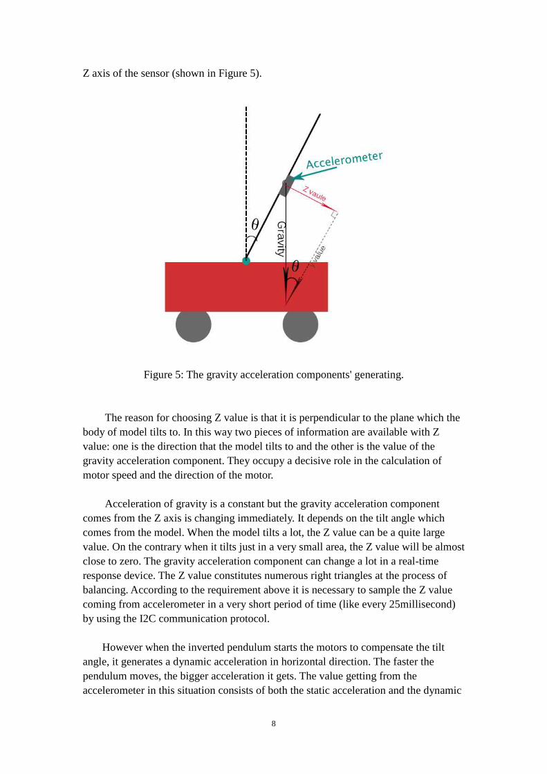
Z axis of the sensor (shown in Figure 5).
Figure 5: The gravity acceleration components' generating.
The reason for choosing Z value is that it is perpendicular to the plane which the
body of model tilts to. In this way two pieces of information are available with Z value: one is the direction that the model tilts to and the other is the value of the gravity acceleration component. They occupy a decisive role in the calculation of motor speed and the direction of the motor.
Acceleration of gravity is a constant but the gravity acceleration component
comes from the Z axis is changing immediately. It depends on the tilt angle which comes from the model. When the model tilts a lot, the Z value can be a quite large value. On the contrary when it tilts just in a very small area, the Z value will be almost close to zero. The gravity acceleration component can change a lot in a real-time response device. The Z value constitutes numerous right triangles at the process of balancing. According to the requirement above it is necessary to sample the Z value coming from accelerometer in a very short period of time (like every 25millisecond) by using the I2C communication protocol. However when the inverted pendulum starts the motors to compensate the tilt angle, it generates a dynamic acceleration in horizontal direction. The faster the pendulum moves, the bigger acceleration it gets. The value getting from the accelerometer in this situation consists of both the static acceleration and the dynamic

9
acceleration. The value used to calculate the tilt angle is affected by the dynamic acceleration which means the accelerometer gets a lot of noise. Therefore the data coming out from the accelerometer must be filtered otherwise the controller will not work.
2.5 Filter
In most cases of signal processing or applied mathematics, the existence of filter is really essential. It helps to reduce the noises or disturbance from the outside system. It plays a big role in optimizing the data object and minimizing errors in the functions. Filters can be set either before the sampling data handled or later in the structure of controller formula. The former one, to some extent, seems to recreate the trend of the data to meet the requirement while the later one makes the current output value generated from the current input data, a certain number of the former input datas and the former output values. Averaging filter [12] is the typical case of the first kind of filters. This filter saves certain number of signal datas and calculates them in average to get a new one and then outputs the newer. Though it is a common filter used in smooth the signal data, it has a big disadvantage of phase lag which may cause big lag during the response time of the system.
(1)
� Y[n] is the output signal � X[n] are the input signals � b0~bp are the coefficients
b0~bp are the coefficients deciding how much influence each sample value does to the current output value. They can be set equally or unequally to fit into different situations.
IIR filter (infinite impulse response) [13] works as the second kind of filters. It reaches an output value by the manipulation with the current input values, input and output values in last periods.
(2)
10
� Y[n] is the output � X[n] are the input signals � b0~bp are the feedforward filter coefficients � a1~aq are the feedback filter coefficients � Q is the feedback filter order
This kind of filter uses less order than averaging filter and it needs less storage units. It is more efficient.
2.6 PID controller
2.6.1 PID controller
PID controller is a control loop with feedback mechanism. It is widely used in industrial control system. P, I, D represent proportion, integration and differential. The controller uses the definition of "error" to represent the difference between the measured variable and the target setvalue. The controller compensates the error during the loop.
P, I, D work as three separate constant parameters in the controller. By tuning the
three parameters in the controller, the system gives different performance to meet the specific requirement. The response of the controller is either overshoots the setvalue or different levels of system oscillation.
During the tuning if proportional factor is too small, accordingly inadequate
regulation, the output of the system changes slowly and requires more adjusting time. If the scale factor is too large which means too big intensity of the control, it will result in beyond regulation causing back and forth oscillation. Increasing the P scale factor makes the system response quickly. Meanwhile the speed of regulation becomes fast which can reduce the static error. In reverse situation the P scale factor increases the oscillation of the system, longer regulation time, deterioration of dynamic performance and even makes the control loop system unstable.
With simple proportional control it is impossible to make the perfect regulation and completely eliminate the error. It needs help from other scale factors.
Lag is one of the reasons causing the instability of the control loop. Since the
differential term can “detect” the trend of the errors’ change, this ability can offset the lag. Appropriate differential scale factor can reduce the overshoots and increase the stability of the system. Effect of the differential term is proportional to the differential time. The greater the differential is, the stronger the differential effect. The disadvantage of a differential term is that the differential control is noise-sensitive

11
which reduces the ability of anti-disturbance. Thus filter is added to this part. The original PID controller is a continuous time system. But now PID control
algorithm is realized by the computer program so the continuous time signal read from the sensor must be sampled and quantized into digital in order to enter the computer's memory and register. This is called the discrete-time form of a PID controller. It is designed for this situation. In this way the PID controller is periodically executed and the implementation cycle is called a sampling period.
Sampling period is another parameter in some transformation of PID controller. The smaller the sampling period, the more samples can reflect changes in analog mode. However if the sample period is too small, the work of the CPU will increase and the difference between two samples will be really small which leads the derivative part of PID controller’s output to be close to zero.
The method is applied in the keeping balance part. The following flowchart shows the controller working in the system.
Figure 6: Diagram of the PID controller in this project
As is shown in Figure 6, Vset is the desired value. The difference between it and
the current sensor value which is called Vsensor is the Verror in the Figure. Verror goes through the PID controller and is calculated in the formula to reach a control value for the system. When the regulation is done by certain devices, the sensor reads the value again to check the current state and the feedback goes into the control loop. The ceaseless loop is doing all the time until the program stops.

12
In our case, Vset is set to zero to symbolize the inverted pendulum’s position
which is vertical. Because the value of one axis from accelerometer is zero when it is put in vertical position to the ground. The difference between it and the current accelerometer value goes through the PD controller to reach a control value for the motor.
2.6.2 PID controller with filter
When dealing with the signals with great noise in it, a low pass filter can be implanted directly into the PID controller [14] formula. It works directly in the derivative term by means of the differential transformation. Here goes the formula:
(3)
� Kp is proportional gain � Td is derivative time � E(t) is the error value calculated by the system � D(t) is derivative gain in discrete-time form � N is the variable controlling the scale of frequency
Figure 7: Working mechanism of parameter N in a low pass filter
“A” is the amplification of the signal. It can be seen from Figure 7. The parameter N here is in a dominant place which decides the range of the frequency to

13
pass this filter. It limits the output of the signal when the frequency increases. The smaller the parameter, the less high frequency is able to get through the filter. Once there is less high frequency data calculated in the formula above, less numerical mutation turns up in the input value of the PID controller which indicates that the filter works.
2.7 Build the model
Referring to balance the robot, how to build the inverted pendulum model is of paramount importance. Model structure for balancing plays a decisive role in almost. The height, weight and the position of the sensor are the factors which can have a great impact on the balance of inverted pendulum. After referring to successful examples, we decide to build an inverted pendulum model to keep its balance.
An inverted pendulum [15] is a model which has its pivot point below its mass. It is often implemented with the pivot point mounted on mechanical vehicles which can move at the horizontal direction.
Figure 8: Structural representation of the lateral section.
The reason for choosing an inverted pendulum structure is that it has a series of
advantages such as flexible movement, automatic control, simple operation, wide range of uses, suitable for small space to run and so on.
The pivot point of this model (in Figure 8) is located in the middle of the plane of the wheel axis. The mindstorm brick is put at the top position because most of the

14
weight comes from it due to the six batteries which hold a significant weight compared with other parts. In this way the structure of the model can be guaranteed that the center of gravity is higher than the model's pivot point.
The model should be built up the higher the better because the higher one allows
the controller to response in a longer time. It also gives the motors enough time to react better. However the higher structure implies that the range-of-motion should be increased in order to overcome its falling by the self-gravity factor. So the requirements of motor efficiency should be enhanced to guarantee the faster movement. But in this project, the range of the tilt angle is restrained within a small area. Therefore this kind of structure design is more good than harm.
Another decisive factor of the balancing is the position of the accelerometer. The motors generate the dynamic acceleration during the process of moving the inverted pendulum. In this view putting the accelerometer near the center of gravity can minimize the influence of the dynamic acceleration as much as possible.
The inverted pendulum is unstable in static or non-control state. However control theory can be applied to the inverted pendulum which makes it stable at an equilibrium position. The control theory goes to the PID controller.

15
3.... SOLUTION
3.1 Generate Eclipse project
3.1.1 Solder the physical media for J-TAG interface
In the ARM processor, one can directly control the internal bus, I / O port and other information by ARM J-TAG and in this way to download files and realize the online real time debugging. To enable the J-TAG communication, physical media must be set up first between the mindstorm master brick board and the interface of the J-TAG connector. The pins of different function should be in correspondence. The reference electronic schematic can be found from the Lego Mindstorm official website.
Figure 9: ARM J-TAG interface Figure 10: J17 pin on the board
The sequence of J-TAG - PIN on the board: 1-8 vcc 3.3v ; 3-7 PU10k ; 5-5 TDI ; 7-2 TMS ; 9、11-1 TCK ; 13-3 TDO ; 15-4 RESET ; 4-6 GND ;

16
Figure 11: Wires for the J-TAG connector
3.1.2 Merge, compile and link all the files into binary file
A binary file containing the instructions in machine language needs to be generated. In order to evoke the potential functions that the mindstorm has, codes of the interfaces of the devices and auxiliary tools on the master brick should be assembled to provide the basic functions. The way to gather information is in reference from the mindstorm official operating system code.
The open source operating system files of the NXT-G is organized in several
levels. The higher level presents the functions named unambiguous for direct call while the lower level focuses on implementing the functions. The lowest level plays a role in dealing with the hardware part, registers, signals and etc. All the concerned c files and assembly files are picked as source files to be transformed into the final binary file. After the binary file is generated successfully, the modified makefile containing the instruction of download works in the Eclipse to download the modified operating system files to the mindstorm board. The size of the binary file is 256KB and it takes 33 seconds for downloading.
The soldering part is hidden in the brick. The wires for the J-TAG connector is put through a hole on the master brick in order not to be destroyed by dragging or moving.

17
3.2 Keep Balance
3.2.1 Control the motor
As an inverted pendulum the part lower than the center gravity is driven by the motors acting like a pendulum.
Servo motors [16] provide inverted pendulum with capability of movement.
There is a built-in rotation sensor in each servo motor which lets user to control the movement of it. The function of the rotation sensor measures motor rotations by degrees or adequate rotations.
One system call, dOutputSetMode, simply initiates one motor. Choose the number of the motors and set the parameter as "BRAKE"[17].
The code as follows: dOutputSetMode(MOTOR_A,BRAKE); dOutputSetMode(MOTOR_B,BRAKE);
The second system call dOutputEnableRegulation means setting the second motor belonging to the previous motor because two motors should be used simultaneously.
The code as follows: dOutputEnableRegulation(MOTOR_B,REGSTATE_SYNCHRONE); /*set B belongs to A*/
The function dOutputSyncMotorPosition maintains the second motor in a synchronized way with the motor set first. One can control the two motors simultaneously by using this system call. The order of the two parameters like (MOTOR_A,MOTOR_B) means MOTOR_B subordinates to MOTOR_A in this command. The code as follows: dOutputSyncMotorPosition(MOTOR_A,MOTOR_B);
After the two motors are synchronized in control, another system call dOutputSetSpeed is used to set the speed for two motors. The parameter MOTOR_RUN_STATE_RUNNING means the motor runs indefinitely.
The code as follows: dOutputSetSpeed (0,MOTOR_RUN_STATE_RUNNING,speed,0);
18
dOutputSetSpeed (1,MOTOR_RUN_STATE_RUNNING,speed,0);
The parameter "speed" in this statement is not a certain value. The PID controller determines how much the speed is needed at that time.
3.2.2 Screen
For the sake of modifying the controller values, the user can create a function to show some key values on the screen. It provides a convenient platform for user to examine quickly what happens during a real-time embedded system.
One system call cDisplaySetPixel has two parameters which specifies the location of the abscissa and ordinate of the pixel and shows the pixel on the screen. Another system call cDisplayClrPixel is almost the same principle as the cDisplaySetPixel command. It clears the pixel in the position where you want. This is used as a method cleaning the specified position.
Here creates a function called “putdigit” which is composed of a primary
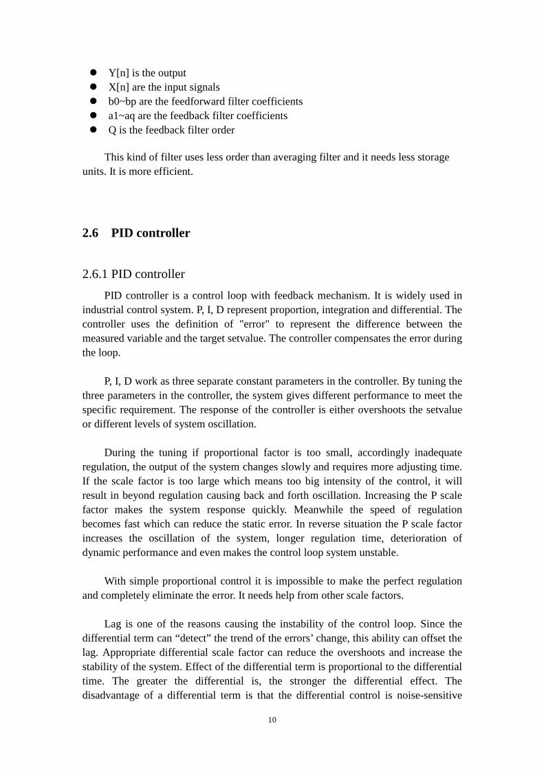
function provided by the NXT-G operating system. It directly shows digit 0-9 in the required places. In order to keep the value shown on the screen through the whole testing period, the function should be put in the main loop to be executed every 1ms. Each digit consists of a 6*8 pixel matrix as shown in the Figure 12. Using "putdigit" function can let users print out the digit at the place they want. The code below shows the way to print the digit one on screen. The rest of the digits are printed in the same way.
putdigit(int x){ switch (x) { case 1:{ cDisplaySetPixel(2,0); cDisplaySetPixel(2,1); cDisplaySetPixel(2,2); cDisplaySetPixel(2,3); cDisplaySetPixel(2,4); cDisplaySetPixel(2,5); cDisplaySetPixel(2,6); break; } Figure 12: Put digit ...
19
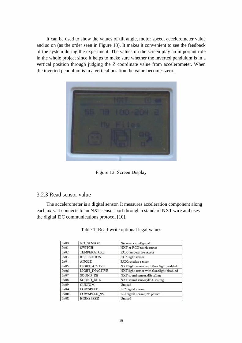
It can be used to show the values of tilt angle, motor speed, accelerometer value
and so on (as the order seen in Figure 13). It makes it convenient to see the feedback of the system during the experiment. The values on the screen play an important role in the whole project since it helps to make sure whether the inverted pendulum is in a vertical position through judging the Z coordinate value from accelerometer. When the inverted pendulum is in a vertical position the value becomes zero.
Figure 13: Screen Display
3.2.3 Read sensor value
The accelerometer is a digital sensor. It measures acceleration component along each axis. It connects to an NXT sensor port through a standard NXT wire and uses the digital I2C communications protocol [10].
Table 1: Read-write optional legal values

20
According to the table above, it is important to choose the correct sensor type for an input port. The type of sensor should be chosen as LOWSPEED here because the accelerometer must use the digital I2C communication protocol.
After this statement takes effect, you can start the next step to read sensor value: if (Port==3) /*the number of the accelerometer's port is set as No.4 and the start number of the port is 0 in the system call*/ IOMapInput.Inputs[Port].SensorType=10; /*choose the sensor type as LOWSPEED*/
All sensors that use I2C communication are named digital sensors because they involve an external micro-controller that deals with the sampling of the physical environment. Every port of this kind for digital sensors can be used in either input or output and they all transmit binary data over the I2C bus.
The NXT-G firmware offers three system calls to communicate over the I2C bus. Before the digital sensor port can be used by users, it must be configured to the I2C communication protocol by using the three system calls and wait for the configuration done.
A system call named CommLSCheckStatus provides an easy way to check that the previous data transmission with an I2C device was successful or not. If the feedback is error 32 that means the previous communication attempt is still in a suspended state. So the only thing you can do is waiting. If the feedback is a negative number then there must be some errors which should be checked again.
The system call named CommLSWrite performs an effect of initiating the I2C communication between the master and the slave. The master device sends commands to an I2C slave by using this system call. When it is called, the number of bytes should be specified the status for the slave's response. If the user specifies the status as zero that means he gives a command to the slave device and expect no reply. If the feedback is a positive number, the NXT transmits the command and waits for the slave to respond. The parameter of this call includes port number, length of buffer, input buffer name and the length of reply buffer. The information in the input buffer contains an I2C address and an internal address in the sensor for communication. It is necessary to create an array to store those buffer values. The length of buffer is 8 bytes. Use this statement to let the master transmit data to the slave: do{status=cCmdLSWrite(3,2, pBuf, 8);} while(status=0); /*no special action is required*/

21
The last system call is CommLSRead which is simply used to retrieve the previous information from the output buffer. As the following code shows: do{status=cCmdLSRead(3, 8, pOutBuf);} while(status=0); /*no special action is required*/ The output buffer is a firmware internal buffer and it always contains the slave's response. We transfer the internal buffer to a local variable before using. The user can get the three axes values of the accelerometer successfully after using the three system calls. These values are all in binary form so they should be converted to decimal form by manual operation.
3.2.4 Get tilt angle
After using the I2C communication protocol to get the Z value from the accelerometer, a mathematical way should be used to measure the tilt angle by using the gravity acceleration together with the Z value, the component of the gravity acceleration.
Since the two gravity acceleration components and the gravity constitute a right-angled triangle, the Z value can be seen as a right-angle edge. Obviously, using an inverse circular trigonometric function "arcsin" is a way to calculate the accurate degree of the tilt angle and even get the direction.
According to the theorem if x is a really small value like 5 degree, the value of the sin x can be recognized as proximately equal to x. These values are both the radian values. The deviation can be ignored in the low-precision experiment on account of the accidental error in the experiment operation is larger than it. But this theorem just takes effect when the degree is very small. The deviation becomes larger when the degree is a larger value. As we simplify the calculation of the tilt angle, the code is shown below: angle=(double)zval/(double)206; /*206 is the default value of the gravity in accelerometer scale*/ angle=angle*180/M_PI;/*convert a radian value into a degree value*/
3.2.5 Application of PID controller formula
To create a system controller, the first thing is to decide which parameters in the PID are suitable for the case. In this balancing project, P & D are used. I is used to get rid of the static error which represents the difference between the output value with

22
the set value when the system gets the stable state. It is not essential for this case because it is a dynamite system and the static error is not fatal. However this object may contain the lag situation and the inverted pendulum has a part with large inertia. So D value must be used to make the inverted pendulum stable. Except those values, the sampling period of the controller is also an important parameter. To control the time gap we get samples from the accelerometer, timer function is created to support. A function named dTimerRead which can count the time tick when the system is turned on is selected for the timer function.
int SampleTime(){ if(dTimerRead()>=(tichcounter+sampletime)){ tickcounter=tickcounter+sampletime; return 1; } else return 0; } This function is executed every 1 ms. Tick counter is implemented in the system and increases every 1 ms. Variable tickcounter starts together with the operating system. When it reaches the set time, the function accumulates the sample time as a reset of timer. When the P,D parameters are chosen to be used in the controller the formula should be changed from the standard continue-time form into discrete-time form. The discrete-time form is the one transformed by mathematical ways which derivatied from the standard PD controller. That is done to give optimized performance. U(n)=Kp*E(n)+Kd*[E(n)-E(n-1)]/ ⊿n (4)
� Kp is proportional gain � Kd is gain of the derivative term � U(n) is output control value � E(n) is the error � n is the ordinal number of sampling period Then the low pass filter is directly added to the deferential part.
(5)
� Kp is proportional gain
23
� Td is derivative time � E(n) is the error value calculated by the system � D(n) is derivative gain in discrete-time form � N is the variable controlling the scale of frequency � n is the ordinal number of sampling period
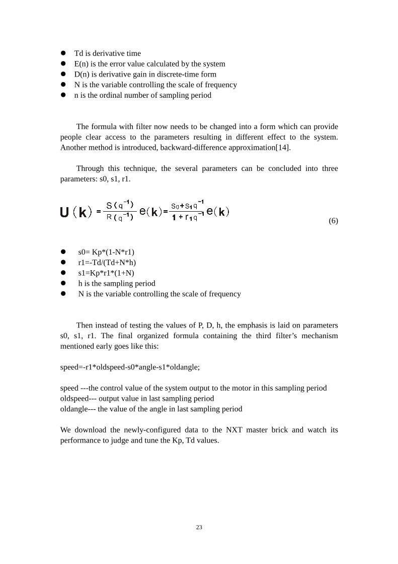
The formula with filter now needs to be changed into a form which can provide people clear access to the parameters resulting in different effect to the system. Another method is introduced, backward-difference approximation[14].
Through this technique, the several parameters can be concluded into three parameters: s0, s1, r1.
(6)
� s0= Kp*(1-N*r1) � r1=-Td/(Td+N*h) � s1=Kp*r1*(1+N) � h is the sampling period � N is the variable controlling the scale of frequency
Then instead of testing the values of P, D, h, the emphasis is laid on parameters s0, s1, r1. The final organized formula containing the third filter’s mechanism mentioned early goes like this: speed=-r1*oldspeed-s0*angle-s1*oldangle; speed ---the control value of the system output to the motor in this sampling period oldspeed--- output value in last sampling period oldangle--- the value of the angle in last sampling period We download the newly-configured data to the NXT master brick and watch its performance to judge and tune the Kp, Td values.

24
Table 2: Result of testing with parameter Kp, Td
N
Sampling
Period(ms) Kp Td maintain time behavior
8 13 30 0.007 /
amplitude of vibration is big,
no shaking
8 13 35 0.01 /
amplitude of vibration is big,
a little shaking
8 13 30 0.005 1
amplitude of vibration gets smaller,
little shaking
8 13 30 0.003 1 almost same
8 13 27 0.002 1 almost same
8 13 23 0.003 1.5 almost same
8 13 23 0.0015 almost same
8 13 23 0.0007 2 almost same
8 13 23 0.0004 2.5 almost same
8 13 23 0.0002 2 almost same
8 13 20 0.0004 almost same
8 13 20 0.0007 1.5 almost same
8 13 23 0.0005 2 almost same
8 13 23 0.0003 2 almost same
At first, the Td value is set to zero and Kp is the value that controls the system behavior. The value assumed first is sixty percent of the motors’ max power ability. With only the Kp value, the pendulum is not able to keep balance. This procedure is just to check the approximate minimum of the Kp that can drive the motor to compensate the tilt angle before pendulum falls down. By part of the table, Kp value shows the tendency of decrease. After this step, next thing is to find a suitable Td value. This value should be increased little by little and judged through pendulum’s tendency of vibration. The good pair of values can let the pendulum vibrate in a small range of angle and the speed of motor decreases during the compensation time. When the pendulum reaches the vertical position, it stops. The system cannot make sure that the testing gives out a good pair of values. So after getting the rough values for the Kp, Td, N and h, formula is changed into another way for better range of tuning. This is called the “zero-pole form”.
U(k)=p * U(k-1)-K*[y(k)-z* y(k-1)] (7) � K=K0*(1-p)/(1-z)

25
For now, p, z and K0 are calculated on basis of the rough but relatively good pair of PD values. Delicate tuning is to change the p, z values in range 0<p<z<1 to perfect the values.
Table 3:Result of testing with parameter p, z p z k0 maintain time behavior
0.5 0.6 20 2
0.5 0.9 20 a little shake
0.5 0.5 20
0.5 0.8 20 a little shake
0.1 0.2 20 1.5
0.2 0.3 20 2
0.3 0.4 20 2.5
0.4 0.5 20
0.3 0.5 20 3
0.3 0.6 20 shaking
0.3 0.5 18 not quickly enough to response
0.3 0.5 23 similar to k0=20
0.3 0.5 28 3
0.3 0.5 35 a little shake
0.3 0.5 25 3.5
Once it is in balance state, suddenly the data with noise from the accelerometer will destroy the system. So for now, the pendulum can keep balance for approximate 5 seconds.
3.2.6 NXT-g project
Together with the mindstorm kit, Lego Company also provides the edition of the NXT-G software. To compare the project working in different working environments, NXT-G project is set up exactly as the one in Eclipse.
26
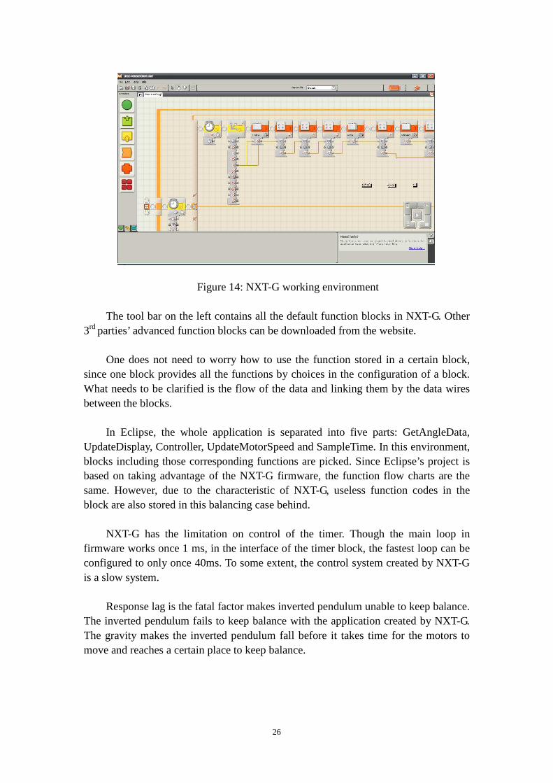
Figure 14: NXT-G working environment
The tool bar on the left contains all the default function blocks in NXT-G. Other
3rd parties’ advanced function blocks can be downloaded from the website. One does not need to worry how to use the function stored in a certain block,
since one block provides all the functions by choices in the configuration of a block. What needs to be clarified is the flow of the data and linking them by the data wires between the blocks.
In Eclipse, the whole application is separated into five parts: GetAngleData,
UpdateDisplay, Controller, UpdateMotorSpeed and SampleTime. In this environment, blocks including those corresponding functions are picked. Since Eclipse’s project is based on taking advantage of the NXT-G firmware, the function flow charts are the same. However, due to the characteristic of NXT-G, useless function codes in the block are also stored in this balancing case behind.
NXT-G has the limitation on control of the timer. Though the main loop in
firmware works once 1 ms, in the interface of the timer block, the fastest loop can be configured to only once 40ms. To some extent, the control system created by NXT-G is a slow system.
Response lag is the fatal factor makes inverted pendulum unable to keep balance.
The inverted pendulum fails to keep balance with the application created by NXT-G. The gravity makes the inverted pendulum fall before it takes time for the motors to move and reaches a certain place to keep balance.

27
3.2.7 RobotC project
Figure 15: RobotC working environment
RobotC is a C-based programming language with a simple development
environment [1]. It supports several different robotics platforms including Lego mindstorm NXT.
RobotC has almost the same way to programme applications as Eclipse because they both use C language to programme. So the structure of the code is similar to Eclipse except the system call. RobotC improves the system calls inside the NXT-G and also adds some own functions to let users do the implementation more convenient and effective.
RobotC firmware does not need to be downloaded separately because when you download the software, the firmware has already existed in your source file. You can also get the software specification from RobotC homepage and download it directly.
The interfaces for using external devices are different from Eclipse. If one wants to use the accelerometer under Eclipse environment, he calls the matching functions for setting up communication or initialization. However one just needs to download the module of the accelerometer as a ".h" file and imports it before implementing accelerometer under the RobotC environment.
RobotC also supports debugging. This factor makes it become a nice workplace for Lego mindstorm kits.

28
4. Result & Discussion This project has been implemented to help let Mindstorm kits be directly programmed in the Eclipse embedded working environment. Furthermore, to show the successful connection, an inverted pendulum is made to work as a demonstrator. With a modified makefile, the commercial free software Eclipse can provide people an integrated working environment which uses the standard programming language. After installing the driver of J-TAG connector, one can download the newly compiled binary file to the NXT master brick and start the function. With the help of NXT-G open source firmware, functions are implemented in a clear and systematic way. Besides this project, there are other working environments particularly designed to handle the mindstorm kit. In order to give an estimate of this Eclipse working environment, here listed some results of the comparison. From the perspective of basic property:
Table 4: Comparison of three working environment in basic property
Eclipse NXT-G RobotC
Software size(with auxiliary tool) 365.3MB 327MB 15MB
Payment N Y Y
Way of transmission JTAG USB USB
Auxiliary tool configuration Y N N
Suited People C programmer not limited C programmer
Those three working environment aims at different crowd. The NXT-G and
RobotC need little configuration on software and are more easily to get started. But commercial-free Eclipse seems more suitable for students or learners to dig into the working mechanism behind and learn more about the hardware. From the perspective of practicability:
Table 5: Comparison of three working environment in practicability
Eclipse NXT-G RobotC
Configuration Difficulty Mid Low Low
Download Speed (for this project) 33 seconds 7 seconds 2 seconds
Standard Debugging N(for now) N Y
Allowable sampling period 1ms 40ms 1ms
Degree of Freedom High Mid High
Expansibility(new interface compatibility) High Mid High

29
NXT-G and RobotC are perfect software for mindstorm kit so that they are easy to use and can transmit the applications very fast. Eclipse is not so orientedly modified that it performs not as well as the other two. But it has the potential ability to work better with more effective and accurate configuration and powerful auxiliary tools. Degree of freedom means how unrestrictedly one can implement he logic or the structure in the application. Since NXT-G has prearranged blocks, users must work following the sequence or procedure limited by the blocks. In other words, Eclipse and RobotC can realize the programmers’ thoughts. Expansibility means the compatibility when the mindstorm has new technology. Eclipse and RobotC are better than NXT-G because they use hardware from the lowest level of operating system directly and when new technology appears, the changes can be handled by calling different lowest level functions. However NXT-G must wait for some 3rd party to provide the new blocks as interface.
The demonstrator, inverted pendulum, has been implemented in the Eclipse working environment. Controlled by the PID controller and getting feedback from the accelerometer sensor, the inverted pendulum can stand for approximate five seconds. When the system is in a stable state, the inverted pendulum will tilt in a very small range of angle. The motor then starts to compensate the error to keep balance.
Figure 16: Balance of the inverted pendulum

30
5. Conclusion
The main point of this project is to constitute an embedded working environment which can directly handle the mindstorm kits providing user a feasible and convenient way to work with the mindstorm kits. The most challenging part is modifying the makefile in the Eclipse which supports the foundation of the whole project. The flaw in this working environment is still troublesome that it cannot perform the standard real time debugging. Though an auxiliary function putdigit is created to obliquely perform debugging function, further modification of the makefile should be made to improve the Eclipse working environment. Making an inverted pendulum is a good demonstrator to show the perfect combination of constructing the hardware, manipulating software and logic of programming. After getting control of the motor, accelerometer and screen, the central control algorithm PID controller needs lots of mathematical calculation and repeated site testing. Judging the inverted pendulum’s performance, it still needs more accurate feedback from accelerometer after the motor gets the control value. With some other instrument such as gyroscope, the pendulum can resist to noise disturbance much better. What’s more, a regulated power supply may be another good suggestion to the pendulum since the six alkaline batteries will have wear and tear during the testing process. As is mentioned above, the project is successful but still needs improvement. Together with the project moving on, students experienced the process of searching related information, learning and analyzing information and applying the academic knowledge to practical situations.

31
Reference [1] ROBOTC.net Home of the Best Programming Language for Educational
Robotics[Internet].[cited 2011 April 26]. Available from: http://www.robotc.net/
[2] LeJOS, Java for Lego Mindstorms[Internet].[cited 2011 April 26]. Available from: http://lejos.sourceforge.net/
[3] nxtOSEK project[Internet].[cited 2011 April 27]. Available from: http://lejos-osek.sourceforge.net/
[4] Description of AVR processor NXT Hardware Developer Kit.pdf [Internet].[cited 2011 April 28]. Available from:http://mindstorms.lego.com/en-us/support/files/default.aspx
[5] YAGARTO-Yet another GNU ARM tool chain[Internet].[cited 2011 April 30]. Available from:http://www.yagarto.de/
[6] Definition of binary file[Internet].[cited 2011 April 30]. Available from: http://www.kb.iu.edu/data/afrw.html
[7] James P. Lynch & Grand Island,Using Open Source Tools for AT91SAM7 Cross Development[Internet].[cited 2011 May 1]. Available from: http://www.olimex.com/dev/arm-usb-ocd.html
[8] Classification of Operating System[Internet].[cited 2011 May 1]. Available from: http://www.wisegeek.com/what-is-an-operating-system.htm
[9] Open Source firmware of NXT-G[Internet].[cited 2011 May 3]. Available from: http://www.iar.com/website1/1.0.1.0/1518/LEGO%20Open%20Source%20License%20Agreement%201.0.pdf
[10] I2C Protocol[Internet].[cited 2011 May 3]. Available from: http://www.robot-electronics.co.uk/
[11] NXT Acceleration / Tilt Sensor (NAC1040)[Internet].[cited 2011 May 5]. Available from: http://www.hitechnic.com/cgi-bin/commerce.cgi?preadd=action&key=NAC1040
[12] Averaging filter[Internet].[cited 2011 May 6]. Available from: http://lorien.ncl.ac.uk/ming/filter/filave.htm
[13] Infinite Impulse Response (IIR) Filters[Internet].[cited 2011 May 8].Available from:http://idlastro.gsfc.nasa.gov/idl_html_help/Infinite_Impulse_Response_%28IIR%29_Filters.html
[14] Karl J. Astrom, Tore H. Hagglund PID Controllers: Theory, Design and Tuning, ISBN, 1-55617-516-7(1995)
[15] Inverted pendulum[Internet].[cited 2011 May 8].Available from: http://www.biomechanika.lt/index.php?option=com_content&view=article&id=2&Itemid=2&lang=lt
[16] Servo Motor[Internet].[cited 2011 May 11].Available from: http://www.tiim.info/the_nxt_project/web/background_research.php
[17] Module Mindstorm.Motor[Internet].[cited 2011 May 11].Available from:

32
http://ocaml-mindstorm.forge.ocamlcore.org/doc/Mindstorm.Motor.html
Formula list
(1) The averaging filter, DEALING WITH MEASUREMENT NOISE[Internet].
[cited 2011 April 26]. URL: http://lorien.ncl.ac.uk/ming/filter/filave.htm
(2) IIR filter, Elena Punskaya, Design of IIR Filters.[Internet]. [cited 2011 April 26]. URL:http://www-sigproc.eng.cam.ac.uk/~op205/3F3_6_Design_of_IIR_Filters.pdf
(3) Karl J. Astrom, Tore H. Hagglund, The differential term of PID controller implemented in discrete time form with a low pass filter, PID Controllers: Theory, Design and Tuning, ISBN, 1-55617-516-7(1995)
(4) Discrete time form of PD controller, Finn Haugen, Discretization of simulator, filter, and PID controller. [Internet].2009
URL: http://home.hit.no/~hansha/documents/control/theory/discretization.pdf (5) DirivativeAction, Karl J. Astrom,Tore H. Hagglund, PID Controllers:
Theory,Design and Tuning, ISBN, 1-55617-516-7(1995) (6) Discrete-time PD controller form based on backward-difference approximation,
Karl J. Astrom, Tore H. Hagglund, PID Controllers: Theory, Design and Tuning, ISBN, 1-55617-516-7(1995)
(7) PD controller in zero-pole form

33
Table List
Table 1 Read-write optional legal values Table 2 Result of testing with parameter Kp,Td Table 3 Result of testing with parameter p,z Table 4 Comparison of three working environment in basic property Table 5 Comparison of three working environment in practicability

34
Appendix: Makefile source data # nxtgcc.sf.net # Makefile origin: WinArm #Retail #LEGODOWNLOADDIR = "C:\Programmer\LEGO Software Test\LEGO MINDSTORMS NXT\engine\Firmware" #Edu #LEGODOWNLOADDIR = "C:\Programmer\LEGO Software\LEGO MINDSTORMS Edu NXT\engine\Firmware" #Current (this has to match your machine) LEGODOWNLOADDIR = "C:\Program Files\LEGO Software\LEGO MINDSTORMS NXT\engine\Firmware" #Fantom and GDB (it is the Eclipse project relative position and does not need to be changed) GDBDOWNLOADDIR = "../../../../NXTGCCFANTOM" FIRMWARENAME = LEGO-MINDSTORMS-NXT-Firmware-v1.05.rfw #FIRMWARENAME = "C:\Programmer\LEGO Software Test\LEGO MINDSTORMS NXT\engine\Firmware\LEGO MINDSTORMS NXT Firmware v1.28 beta6.rfw" NEWSTARTOFUSERFLASH = 0x136C00L #Override it in d_loader.h with -DSTARTOFUSERFLASH = $(NEWSTARTOFUSERFLASH) OLDSTARTOFUSERFLASH = 0x124600L #0x12E000L # MCU name and submodel MCU = arm7tdmi SUBMDL = AT91SAM7S256 #SUBMDL = AT91SAM7S512 USE_THUMB_MODE = YES #USE_THUMB_MODE = NO ## Create ROM-Image (final) RUN_MODE=ROM_RUN ## Create RAM-Image (debugging) ##( not used: example does not fit in AT91SAM7S64 RAM ) #RUN_MODE=RAM_RUN ## Exception-Vector placement only supported for "ROM_RUN" ## (placement settings ignored when using "RAM_RUN") ## - Exception vectors in ROM:

35
#VECTOR_LOCATION=VECTORS_IN_ROM ## - Exception vectors in RAM: VECTOR_LOCATION=VECTORS_IN_RAM SRCDIR = UTILSDIR="C:\DocumentsandSettings\yujmao10\Desktop\NXTGCCECLIPSE.0.0.13\NXTGCCECLIPSE\workspace\NXTGCC\LEGO-MINDSTORMS-NXT-Firmware-Open-Source\AT91SAM7S256\nxtgcc\utils" # Target file name (without extension). # comment this out if you do not have the source TARGET = m_sched #TARGET = $(SRCDIR)/nxtgcc # and uncomment this and read the test in main.c #TARGET = main # List C source files here. (C dependencies are automatically generated.) # use file-extension c for "c-only"-files SRC = $(TARGET).c #SRC = m_sched.c #SRC += dbgu.c #SRC += syscalls.c #SRC += swi_handler_user.c #SRC += rprintf.c SRC += Cstartup_SAM7.c SRC += syscalls.c # comment this out if you do not have the source SRC += c_button.c c_display.c c_comm.c c_input.c c_ioctrl.c c_loader.c c_lowspeed.c SRC += c_output.c c_sound.c d_bt.c d_button.c d_display.c d_hispeed.c d_input.c d_sound.c d_timer.c c_ui.c #SRC2 = $(SRCDIR)/c_cmd.c $(SRCDIR)/d_output.c $(SRCDIR)/d_loader.c $(SRCDIR)/d_lowspeed.c $(SRCDIR)/d_ioctrl.c $(SRCDIR)/d_usb.c SRC += c_cmd.c d_output.c d_loader.c d_lowspeed.c d_ioctrl.c d_usb.c # List C source files here which must be compiled in ARM-Mode. # use file-extension c for "c-only"-files SRCARM = nxtdebug.c # List Assembler source files here. ASRC = # List Assembler source files here which must be assembled in ARM-Mode.. ASRCARM = Cstartup.S

36
#ASRCARM += common/swi_handler.S #1.05 binsert section #files BINSERTFILE1 = $(UTILSDIR)/$(FIRMWARENAME) BINSERTADDRESS1SRC = $(OLDSTARTOFUSERFLASH) BINSERTADDRESS1TRG = $(NEWSTARTOFUSERFLASH) BINSERTLENGTH1 = 25104 #filehandles BINSERTFILE2 = $(UTILSDIR)/$(FIRMWARENAME) BINSERTADDRESS2 = 0x3FF00 BINSERTLENGTH2 = 56 #file version BINSERTFILE3 = $(UTILSDIR)/$(FIRMWARENAME) BINSERTADDRESS3 = 0x3FFFC BINSERTLENGTH3 = 4 #There is a make file for binsert in the utils directory (if you for example use Cygwin). BINSERT = $(UTILSDIR)/binsert.exe ## Output format. (can be ihex or binary) ## (binary i.e. for openocd and SAM-BA, hex i.e. for lpc21isp and uVision) #FORMAT = ihex FORMAT = binary # Optimization level, can be [0, 1, 2, 3, s]. # 0 = turn off optimization. s = optimize for size. # (Note: 3 is not always the best optimization level. See avr-libc FAQ.) #OPT = 1 #rup: s is good OPT = s # Debugging format. # Native formats for AVR-GCC's -g are stabs [default], or dwarf-2. # AVR (extended) COFF requires stabs, plus an avr-objcopy run. #DEBUG = stabs DEBUG = dwarf-2 # List any extra directories to look for include files here. # Each directory must be seperated by a space. EXTRAINCDIRS =

37
# List any extra directories to look for library files here. # Each directory must be seperated by a space. #EXTRA_LIBDIRS = ../arm7_efsl_0_2_4 EXTRA_LIBDIRS = ## Using the Atmel AT91_lib produces warning with ## the default warning-levels. ## yes - disable these warnings; no - keep default settings AT91LIBNOWARN = yes #AT91LIBNOWARN = no # Compiler flag to set the C Standard level. # c89 - "ANSI" C # gnu89 - c89 plus GCC extensions # c99 - ISO C99 standard (not yet fully implemented) # gnu99 - c99 plus GCC extensions CSTANDARD = -std=gnu99 # Place -D or -U options for C here CDEFS = -D$(RUN_MODE) CDEFS += -DSAM7S256 -DPROTOTYPE_PCB_4 -D__ICCARM__ -DNEW_MENU CDEFS += -DSTARTOFUSERFLASH=$(NEWSTARTOFUSERFLASH) #This is defined in d_loader.h # Place -I options here CINCS = # Place -D or -U options for ASM here ADEFS = -D$(RUN_MODE) ifdef VECTOR_LOCATION CDEFS += -D$(VECTOR_LOCATION) ADEFS += -D$(VECTOR_LOCATION) endif # Compiler flags. ifeq ($(USE_THUMB_MODE),YES) THUMB = -mthumb THUMB_IW = -mthumb-interwork else THUMB = THUMB_IW =

38
endif # -g*: generate debugging information # -O*: optimization level # -f...: tuning, see GCC manual and avr-libc documentation # -Wall...: warning level # -Wa,...: tell GCC to pass this to the assembler. # -adhlns...: create assembler listing # # Flags for C and C++ (arm-elf-gcc/arm-elf-g++) #CFLAGS = -g$(DEBUG) CFLAGS = CFLAGS += $(CDEFS) $(CINCS) CFLAGS += -O$(OPT) #Enable the following line to see warnings #CFLAGS += -Wall # or enable the following the line to hide all warnings CFLAGS += -w #CFLAGS += -Wcast-align -Wimplicit #CFLAGS += -Wpointer-arith -Wswitch #CFLAGS += -Wredundant-decls -Wreturn-type -Wshadow -Wunused #CFLAGS += -Wa,-adhlns=$(subst $(suffix $<),.lst,$<) CFLAGS += $(patsubst %,-I%,$(EXTRAINCDIRS)) #CFLAGS += -fpack-struct #increases code size too much (using __attribute__((__packed__)) in module.h CFLAGS2 = -ffunction-sections -fdata-sections -ffreestanding # flags only for C CONLYFLAGS += -Wnested-externs CONLYFLAGS += $(CSTANDARD) ifneq ($(AT91LIBNOWARN),yes) #AT91-lib warnings with: CFLAGS += -Wcast-qual CONLYFLAGS += -Wmissing-prototypes CONLYFLAGS += -Wstrict-prototypes CONLYFLAGS += -Wmissing-declarations endif # Assembler flags. # -Wa,...: tell GCC to pass this to the assembler. # -ahlns: create listing # -g$(DEBUG): have the assembler create line number information ASFLAGS = $(ADEFS) -Wa,-adhlns=$(<:.S=.lst),--g$(DEBUG)

39
#Additional libraries. # Extra libraries # Each library-name must be seperated by a space. # To add libxyz.a, libabc.a and libefsl.a: # EXTRA_LIBS = xyz abc efsl #EXTRA_LIBS = efsl EXTRA_LIBS = #Support for newlibc-lpc (file: libnewlibc-lpc.a) #NEWLIBLPC = -lnewlib-lpc MATH_LIB = -lm # Linker flags. # -Wl,...: tell GCC to pass this to linker. # -Map: create map file # --cref: add cross reference to map file LDFLAGS = -nostartfiles -Wl,-Map=$(TARGET).map,--cref,--gc-sections LDFLAGS += -lc #LDFLAGS += -s LDFLAGS += $(NEWLIBLPC) $(MATH_LIB) LDFLAGS += -lc -lgcc LDFLAGS += $(CPLUSPLUS_LIB) LDFLAGS += $(patsubst %,-L%,$(EXTRA_LIBDIRS)) LDFLAGS += $(patsubst %,-l%,$(EXTRA_LIBS)) # Set Linker-Script Depending On Selected Memory and Controller ifeq ($(RUN_MODE),RAM_RUN) LDFLAGS +=-T$(SUBMDL)-RAM.ld else LDFLAGS +=-T$(SUBMDL)-ROM.ld #AT91SAM7S256-ROM.ld is used as default endif #This is an environment variable set in the Eclipse launch config ifdef ECLIPSE_HOME #@echo eclipse_home is $(ECLIPSE_HOME) ARMELFGCCLOC = ."$(ECLIPSE_HOME)armelfgcc/bin/" #MSYSLOC = ."$(ECLIPSE_HOME)msys/1.0/bin/" MSYSLOC = "C:\Documents and Settings\yujmao10\Desktop\NXTGCCECLIPSE.0.0.13\NXTGCCECLIPSE\eclipse\msys\1.0\bin\"
40
endif # Define programs and commands. SHELL = $(MSYSLOC)sh #Codesurgery #ARMCHAIN = none-eabi #Others ARMCHAIN = elf CC = $(ARMELFGCCLOC)arm-$(ARMCHAIN)-gcc CPP = $(ARMELFGCCLOC)arm-$(ARMCHAIN)-g++ OBJCOPY = $(ARMELFGCCLOC)arm-$(ARMCHAIN)-objcopy OBJDUMP = $(ARMELFGCCLOC)arm-$(ARMCHAIN)-objdump SIZE = $(ARMELFGCCLOC)arm-$(ARMCHAIN)-size NM = $(ARMELFGCCLOC)arm-$(ARMCHAIN)-nm REMOVE = $(MSYSLOC)rm -f COPY = $(MSYSLOC)cp MOVE = $(MSYSLOC)mv LIST = $(MSYSLOC)ls # Define Messages # English MSG_ERRORS_NONE = Errors: none MSG_BEGIN = "-------- begin (mode: $(RUN_MODE)) --------" MSG_END = -------- end -------- MSG_SIZE_BEFORE = Size before: MSG_SIZE_AFTER = Size after: MSG_FLASH = Creating load file for Flash: MSG_EXTENDED_LISTING = Creating Extended Listing: MSG_SYMBOL_TABLE = Creating Symbol Table: MSG_LINKING = Linking: MSG_COMPILING = Compiling C: MSG_COMPILING_ARM = "Compiling C (ARM-only):" MSG_COMPILINGCPP = Compiling C++: MSG_COMPILINGCPP_ARM = "Compiling C++ (ARM-only):" MSG_ASSEMBLING = Assembling: MSG_ASSEMBLING_ARM = "Assembling (ARM-only):" MSG_CLEANING = Cleaning project: MSG_FORMATERROR = Can not handle output-format MSG_LPC21_RESETREMINDER = You may have to bring the target in bootloader-mode now.

41
# Define all object files. COBJ = $(SRC:.c=.o) COBJ2 = $(SRC2:.c=.o) AOBJ = $(ASRC:.S=.o) COBJARM = $(SRCARM:.c=.o) AOBJARM = $(ASRCARM:.S=.o) CPPOBJ = $(CPPSRC:.cpp=.o) CPPOBJARM = $(CPPSRCARM:.cpp=.o) # Define all listing files. LST = $(ASRC:.S=.lst) $(ASRCARM:.S=.lst) $(SRC:.c=.lst) $(SRC2:.c=.lst) $(SRCARM:.c=.lst) LST += $(CPPSRC:.cpp=.lst) $(CPPSRCARM:.cpp=.lst) # Compiler flags to generate dependency files. ### GENDEPFLAGS = -Wp,-M,-MP,-MT,$(*F).o,-MF,.dep/$(@F).d GENDEPFLAGS = -MD -MP -MF dep/$(@F).d # Combine all necessary flags and optional flags. # Add target processor to flags. ALL_CFLAGS = -mcpu=$(MCU) $(THUMB_IW) -I. $(CFLAGS) $(GENDEPFLAGS) ALL_ASFLAGS = -mcpu=$(MCU) $(THUMB_IW) -I. -x assembler-with-cpp $(ASFLAGS) # Default target. all: begin gccversion sizebefore build sizeafter finished end #all: build finished end ifeq ($(FORMAT),ihex) build: elf hex lss sym hex: $(TARGET).hex IMGEXT=hex else ifeq ($(FORMAT),binary) build: elf bin lss sym bin: $(TARGET).bin IMGEXT=bin else $(error "$(MSG_FORMATERROR) $(FORMAT)") endif endif elf: $(TARGET).elf

42
lss: $(TARGET).lss sym: $(TARGET).sym # Eye candy. begin: @echo @echo $(MSG_BEGIN) finished: @echo $(MSG_ERRORS_NONE) end: @echo $(MSG_END) @echo # Display size of file. HEXSIZE = $(SIZE) --target=$(FORMAT) $(TARGET).hex ELFSIZE = $(SIZE) -A $(TARGET).elf sizebefore: @echo 1 echo $(MSG_SIZE_BEFORE) @echo 2 @echo $(ELFSIZE) @echo 3 @if [ -f $(TARGET).elf ]; then echo; echo $(MSG_SIZE_BEFORE); $(ELFSIZE); echo; fi @echo bye sizeafter: @if [ -f $(TARGET).elf ]; then echo; echo $(MSG_SIZE_AFTER); $(ELFSIZE); echo; fi # Display compiler version information. gccversion : @$(CC) --version @echo eclipse_home is $(ECLIPSE_HOME) # Create final output file (.hex) from ELF output file. %.hex: %.elf @echo objcopy to bin @echo $(MSG_FLASH) $@ $(OBJCOPY) -O $(FORMAT) $< $@ %.out: %.elf

43
@echo objcopy to bin @echo $(MSG_FLASH) $@ $(OBJCOPY) -O $(FORMAT) $< $@ # Create final output file (.bin) from ELF output file. %.bin: %.elf @echo @echo $(MSG_FLASH) $@ #gap fill with 0xFF makes the handle table unhappy (0x00 is "free") # $(OBJCOPY) --pad-to=0x140000 --gap-fill 0x00 -O $(FORMAT) $< $@ $(OBJCOPY) --pad-to=0x140000 -O $(FORMAT) $< $@ #It is possible to omit the next two lines if you don't want to get the firmware files inserted #$(BINSERT) $(BINSERTFILE1) $(BINSERTADDRESS1SRC) $(BINSERTLENGTH1) $@ $(BINSERTADDRESS1TRG) #$(BINSERT) $(BINSERTFILE2) $(BINSERTADDRESS2) $(BINSERTLENGTH2) $@ $(BINSERTADDRESS2) $(BINSERT) $(BINSERTFILE3) $(BINSERTADDRESS3) $(BINSERTLENGTH3) $@ $(BINSERTADDRESS3) # $(MOVE) $@ nxtgcc.rfw #Enable this line to copy the firmware to the "LEGO Software\LEGO MINDSTORMS Edu NXT\engine\Firmware" location #Remember to correct the LEGODOWNLOADDIR location first (at the top of this file # or you will get a build script error right here...:-) # $(COPY) nxtgcc.rfw $(LEGODOWNLOADDIR) # $(COPY) nxtgcc.rfw $(GDBDOWNLOADDIR) # $(COPY) $< $(GDBDOWNLOADDIR)/nxtgcc.elf # $(COPY) $< $(GDBDOWNLOADDIR)/nxtgcc.elf # $(LIST) -al *.rfw # Create extended listing file from ELF output file. # testing: option -C %.lss: %.elf @echo @echo $(MSG_EXTENDED_LISTING) $@ $(OBJDUMP) -h -S -C $< > $@ # Create a symbol table from ELF output file. %.sym: %.elf @echo @echo $(MSG_SYMBOL_TABLE) $@ $(NM) -n $< > $@

44
# Link: create ELF output file from object files. .SECONDARY : $(TARGET).elf .PRECIOUS : $(AOBJARM) $(AOBJ) $(COBJARM) $(COBJ) $(COBJ2) $(CPPOBJ) $(CPPOBJARM) %.elf: $(AOBJARM) $(AOBJ) $(COBJARM) $(COBJ) $(COBJ2) $(CPPOBJ) $(CPPOBJARM) @echo $(MSG_LINKING) $@ $(CC) $(THUMB) $(ALL_CFLAGS) $(AOBJARM) $(AOBJ) $(COBJARM) $(COBJ) $(COBJ2) $(CPPOBJ) $(CPPOBJARM) --output $@ $(LDFLAGS) # $(CPP) $(THUMB) $(ALL_CFLAGS) $(AOBJARM) $(AOBJ) $(COBJARM) $(COBJ) $(CPPOBJ) $(CPPOBJARM) --output main.out $(LDFLAGS) # Compile: create object files from C source files. ARM/Thumb $(COBJ) : %.o : %.c @echo @echo $(MSG_COMPILING) $< $(CC) -c $(THUMB) $(ALL_CFLAGS) $(CFLAGS2) $(CONLYFLAGS) $< -o $@ # Compile: create object files from C source files. ARM/Thumb $(COBJ2) : %.o : %.c @echo @echo Higg mem: $(MSG_COMPILING) $< $(CC) -c $(THUMB) $(ALL_CFLAGS) $(CONLYFLAGS) $< -o $@ $(OBJCOPY) --rename-section .text=.text2 $@ # Compile: create object files from C source files. ARM-only $(COBJARM) : %.o : %.c @echo @echo $(MSG_COMPILING_ARM) $< $(CC) -c $(ALL_CFLAGS) $(CONLYFLAGS) $< -o $@ # Compile: create object files from C++ source files. ARM/Thumb $(CPPOBJ) : %.o : %.cpp @echo @echo $(MSG_COMPILINGCPP) $< $(CPP) -c $(THUMB) $(ALL_CFLAGS) $(CPPFLAGS) $< -o $@ # Compile: create object files from C++ source files. ARM-only $(CPPOBJARM) : %.o : %.cpp @echo @echo $(MSG_COMPILINGCPP_ARM) $< $(CPP) -c $(ALL_CFLAGS) $(CPPFLAGS) $< -o $@ # Compile: create assembler files from C source files. ARM/Thumb

45
## does not work - TODO - hints welcome ##$(COBJ) : %.s : %.c ## $(CC) $(THUMB) -S $(ALL_CFLAGS) $< -o $@ # Assemble: create object files from assembler source files. ARM/Thumb $(AOBJ) : %.o : %.S @echo @echo $(MSG_ASSEMBLING) $< $(CC) -c $(THUMB) $(ALL_ASFLAGS) $< -o $@ # Assemble: create object files from assembler source files. ARM-only $(AOBJARM) : %.o : %.S @echo @echo $(MSG_ASSEMBLING_ARM) $< $(CC) -c $(ALL_ASFLAGS) $< -o $@ # Target: clean project. clean: begin clean_list finished end clean_list : @echo @echo $(MSG_CLEANING) $(REMOVE) dep/* $(REMOVE) $(TARGET).hex $(REMOVE) $(TARGET).bin $(REMOVE) $(TARGET).rfw $(REMOVE) $(TARGET).obj $(REMOVE) $(TARGET).elf $(REMOVE) $(TARGET).map $(REMOVE) $(TARGET).obj $(REMOVE) $(TARGET).a90 $(REMOVE) $(TARGET).sym $(REMOVE) $(TARGET).lnk $(REMOVE) $(TARGET).lss $(REMOVE) $(COBJ) $(REMOVE) $(COBJ2) $(REMOVE) $(CPPOBJ) $(REMOVE) $(AOBJ) $(REMOVE) $(COBJARM) $(REMOVE) $(CPPOBJARM) $(REMOVE) $(AOBJARM) $(REMOVE) $(LST) $(REMOVE) $(SRC:.c=.s) $(REMOVE) $(SRC":.c=.s) $(REMOVE) $(SRC:.c=.d) $(REMOVE) $(SRC":.c=.d) $(REMOVE) $(SRCARM:.c=.s) $(REMOVE) $(SRCARM:.c=.d)
46
$(REMOVE) $(CPPSRC:.cpp=.s) $(REMOVE) $(CPPSRC:.cpp=.d) $(REMOVE) $(CPPSRCARM:.cpp=.s) $(REMOVE) $(CPPSRCARM:.cpp=.d) # Include the dependency files. #-include $(shell mkdir .dep 2>/dev/null) $(wildcard .dep/*) -include $(shell mkdir dep 2>/dev/null) $(wildcard dep/*) # Listing of phony targets. .PHONY : all begin finish end sizebefore sizeafter gccversion \ build elf hex bin lss sym clean clean_list #build elf hex bin lss sym clean clean_list program # *************************************************** ******************************************* # FLASH PROGRAMMING (using OpenOCD and Amontec JTAGKey) # # Alternate make target for flash programming only # # You must create a special Eclipse make target (program) to run this part of the makefile # (Project -> Create Make Target... then set the Target Name and Make Target to "program") # # OpenOCD is run in "batch" mode with a special configuration file and a script file containing # the flash commands. When flash programming completes, OpenOCD terminates. # # Note that the make file below creates the script file of flash commands "on the fly" # # Programmers: Martin Thomas, Joseph M Dupre, James P Lynch # *************************************************** ******************************************* # specify output filename here (must be *.bin file) FLASH_TARGET = m_sched.bin # specify the directory where openocd executable resides (openocd-ftd2xx.exe or openocd-pp.exe) OPENOCD_DIR = 'C:\Program Files\openocd-r717\bin\'

47
# specify OpenOCD executable (pp is for the wiggler, ftd2xx is for the USB debugger) #OPENOCD = $(OPENOCD_DIR)openocd-pp.exe OPENOCD = $(OPENOCD_DIR)openocd-ftd2xx.exe # specify OpenOCD configuration file (pick the one for your device) #OPENOCD_CFG = $(OPENOCD_DIR)at91sam7s256-wiggler-flash-program.cfg #OPENOCD_CFG = $(OPENOCD_DIR)at91sam7s256-jtagkey-flash-program.cfg OPENOCD_CFG = $()sam7_auto.cfg # specify the name and folder of the flash programming script file #OPENOCD_SCRIPT = c:\temp\temp.ocd # program the AT91SAM7S256 internal flash memory program: $(FLASH_TARGET) # @echo "Preparing OpenOCD script..." # @cmd /c 'echo wait_halt > $(OPENOCD_SCRIPT)' # @cmd /c 'echo armv4_5 core_state arm >> $(OPENOCD_SCRIPT)' # @cmd /c 'echo flash write 0 $(TARGET) 0x0 >> $(OPENOCD_SCRIPT)' # @cmd /c 'echo mww 0xfffffd08 0xa5000401 >> $(OPENOCD_SCRIPT)' # @cmd /c 'echo reset >> $(OPENOCD_SCRIPT)' # @cmd /c 'echo shutdown >> $(OPENOCD_SCRIPT)' @echo "Flash Programming with OpenOCD..." $(OPENOCD) -f $(OPENOCD_CFG) @echo "Flash Programming Finished."