miniball flexible frame
TRANSCRIPT

Miniball Flexible Frame
Author: Nigel Warr
Date: 6th March 2015.
Contents
1 Overview 2
2 Modifications 32.1 Modifications to the height . . . . . . . . . . . . . . . . . . . . . . . . . . . . . . . . . . . . . 32.2 Modifications to the winding mechanism . . . . . . . . . . . . . . . . . . . . . . . . . . . . . . 32.3 Bridging the trench for HIE-ISOLDE . . . . . . . . . . . . . . . . . . . . . . . . . . . . . . . . 3
3 Frame adjustment 3
4 Target-chamber bridge 5
5 Detector mounting 55.1 Mounting of detector support on frame . . . . . . . . . . . . . . . . . . . . . . . . . . . . . . . 55.2 Mounting of detector in support . . . . . . . . . . . . . . . . . . . . . . . . . . . . . . . . . . 6
6 The new detector ring mountings 7
7 Aligning the detector rings 7
8 Measuring the angles 88.1 Theta . . . . . . . . . . . . . . . . . . . . . . . . . . . . . . . . . . . . . . . . . . . . . . . . . 8
8.1.1 Example (September 2003) . . . . . . . . . . . . . . . . . . . . . . . . . . . . . . . . . 98.2 Phi . . . . . . . . . . . . . . . . . . . . . . . . . . . . . . . . . . . . . . . . . . . . . . . . . . . 9
8.2.1 Example (september 2003) . . . . . . . . . . . . . . . . . . . . . . . . . . . . . . . . . 108.3 Alpha . . . . . . . . . . . . . . . . . . . . . . . . . . . . . . . . . . . . . . . . . . . . . . . . . 10
8.3.1 Example (september 2003) . . . . . . . . . . . . . . . . . . . . . . . . . . . . . . . . . 138.4 Complete example - September 2003 . . . . . . . . . . . . . . . . . . . . . . . . . . . . . . . . 13
1
1 Overview
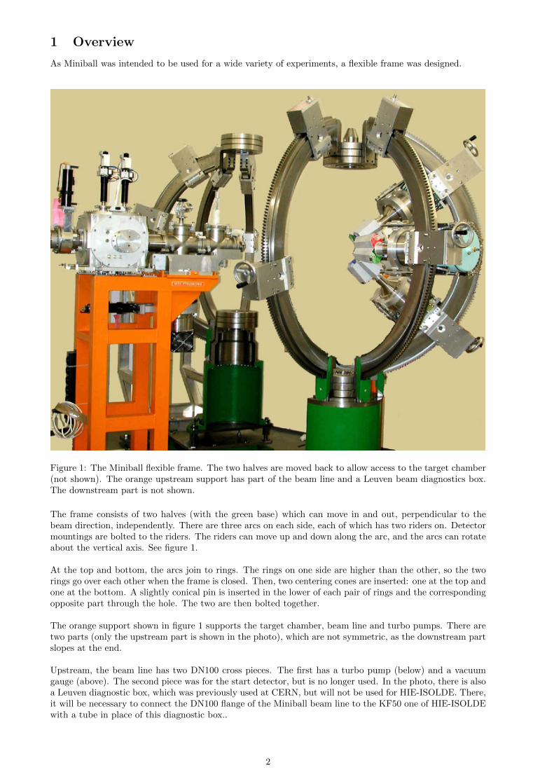
As Miniball was intended to be used for a wide variety of experiments, a flexible frame was designed.
Figure 1: The Miniball flexible frame. The two halves are moved back to allow access to the target chamber(not shown). The orange upstream support has part of the beam line and a Leuven beam diagnostics box.The downstream part is not shown.
The frame consists of two halves (with the green base) which can move in and out, perpendicular to thebeam direction, independently. There are three arcs on each side, each of which has two riders on. Detectormountings are bolted to the riders. The riders can move up and down along the arc, and the arcs can rotateabout the vertical axis. See figure 1.
At the top and bottom, the arcs join to rings. The rings on one side are higher than the other, so the tworings go over each other when the frame is closed. Then, two centering cones are inserted: one at the top andone at the bottom. A slightly conical pin is inserted in the lower of each pair of rings and the correspondingopposite part through the hole. The two are then bolted together.
The orange support shown in figure 1 supports the target chamber, beam line and turbo pumps. There aretwo parts (only the upstream part is shown in the photo), which are not symmetric, as the downstream partslopes at the end.
Upstream, the beam line has two DN100 cross pieces. The first has a turbo pump (below) and a vacuumgauge (above). The second piece was for the start detector, but is no longer used. In the photo, there is alsoa Leuven diagnostic box, which was previously used at CERN, but will not be used for HIE-ISOLDE. There,it will be necessary to connect the DN100 flange of the Miniball beam line to the KF50 one of HIE-ISOLDEwith a tube in place of this diagnostic box..
2
Downstream, there are also two DN100 cross pieces. The first was for the stop detector, but is no longerused. The second is for a turbo pump (below) and a vacuum gauge (above).
2 Modifications
2.1 Modifications to the height
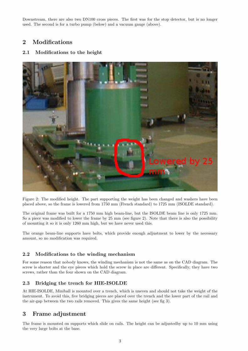
Figure 2: The modified height. The part supporting the weight has been changed and washers have beenplaced above, so the frame is lowered from 1750 mm (French standard) to 1725 mm (ISOLDE standard).
The original frame was built for a 1750 mm high beam-line, but the ISOLDE beam line is only 1725 mm.So a piece was modified to lower the frame by 25 mm (see figure 2). Note that there is also the possibilityof mounting it so it is only 1260 mm high, but we have never used this.
The orange beam-line supports have bolts, which provide enough adjustment to lower by the necessaryamount, so no modification was required.
2.2 Modifications to the winding mechanism
For some reason that nobody knows, the winding mechanism is not the same as on the CAD diagram. Thescrew is shorter and the eye pieces which hold the screw in place are different. Specifically, they have twoscrews, rather than the four shown on the CAD diagram.
2.3 Bridging the trench for HIE-ISOLDE
At HIE-ISOLDE, Miniball is mounted over a trench, which is uneven and should not take the weight of theinstrument. To avoid this, five bridging pieces are placed over the trench and the lower part of the rail andthe air-gap between the two rails removed. This gives the same height (see fig 3).
3 Frame adjustment
The frame is mounted on supports which slide on rails. The height can be adjustedby up to 10 mm usingthe very large bolts at the base.
3

Figure 3: The Miniball flexible frame with bridging over the cable trench for HIE-ISOLDE. The beam goesfrom right to left.
Figure 4: The adjustment of the frame
There is a centering pin marked 75 on the diagram on one side and a hole on the other side. When they arelined up, it is possible to slide a centering cone through the hole in the upper part so that it engages the pin
4

on the lower part. Note that the lower pin is missing in the photograph figure 1.
This same construction is repeated at the top (not shown on figure 4, but visible on the photograph figure 1).
Long screws with handles are used to move the two halves backwards and forwards.
4 Target-chamber bridge
Figure 5: The target-chamber bridge, showing the orange support frame and the bridge with the targetchamber. The beam goes from right to left.
Figure 5 shows the target chamber, the parts of the beam line connected to it and the orange supportstructure. In the original design the DN100 cross pieces of beam line nearest the target chamber were in-tended for the start/stop detectors. The other two are for the turbomolecular pumps and vacuum gauges.Note, however, that the start/stop detectors could not cope with the instantaneous rates and were never used.
Figure 6 shows the bolts, which have to be adjusted to aligne the beamline.
figure 7 shows how the bracket, which is part of the chamber (at the downstream end) sits on a rail. Theupstream end has guiding pins and is connected first. As there is a bellow at the downstream end, there issome flexibility. Once the upstream end is fixed, the bracket is bolted to the rail. During this procedure,the side plates of the target chamber must be attached. Once the bracket is fixed, they can be removed.
5 Detector mounting
5.1 Mounting of detector support on frame
The detector support assembly is mounted onto the rider by four bolts (10 mm diameter, 25 mm length, M6square cup) which go through the holes in the bracket and are screwed into the rider. They use the four innerpositions and there is no thread on the bracket at this point. See figure 8, where the bracket is shown in pink.
Additionally, this bracket has four screws for bolts (10 mm diameter, 20 mm length, M6 square cup) whichare used to align. They are screwed into the four outer positions of the bracket (there is a thread in the
5

Figure 6: The bolts for aligning the beamline. The pink part slides over the green part. The purple bolt isfor locking and the red ones for adjusting.
bracket there) and they do not go into the rider, but press against it. By having the fixing bolts loose, andtightening the alignment bolts, it is possible to align the detector.
Two rods are attached to the bracket, each with four bolts (5 mm diameter, 25 mm length, M5 square cup).
5.2 Mounting of detector in support
In order to mount the detector, one of its handles must be detached on the side closest to the arm on whichthe support is mounted. The other is used to hold the detector.
The detector ring is bolted onto the detector with four bolts (10 mm diameter, 15 mm length, M8 square cutand a specially short 7 mm head, so they fit properly). This innner ring has three pieces of teflon attachedto it. One around the outer edge, and one on each side where it will make contact with the front and backrings. You have to remove one of these in order to get the bolts in, which fix the ring to the detector. Thering fixed to the detector is shown in blue on figure 9. Note, that the back plate of the ring (green in figure9 has to be put in place, before the blue part is fixed to the detector, but it is not screwed down at thisstage. It can move about the preamplifier housing, but cannot come off.
The detector ring, with the detector attached, is inserted into the front ring (pink on figure 9 - note thatthe pink ring is part of the detector support mounted on the frame). Since the head of the detector is widerthan the hole, the neck of the detector is brought sideways through the slot in the ring. Once the detectorring is inserted into the front ring, a back ring is put in and screwed onto the front ring. In this way, thedetector ring (blue) is sandwiched between the front ring (pink) and the back ring (green).
The front ring and the brass braking rings are mounted onto the rods. They can slide up and down, butboth have screws to lock them into position. We always mount a brass ring on each rod for detectors whichare pointing downwards, but only one for those pointing upwards. The brass rings are much better brakesthan the ones built into the detector holder assembly and were added by Cologne as an afterthought.
6
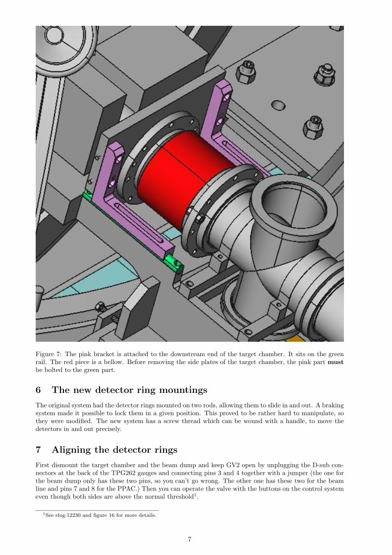
Figure 7: The pink bracket is attached to the downstream end of the target chamber. It sits on the greenrail. The red piece is a bellow. Before removing the side plates of the target chamber, the pink part mustbe bolted to the green part.
6 The new detector ring mountings
The original system had the detector rings mounted on two rods, allowing them to slide in and out. A brakingsystem made it possible to lock them in a given position. This proved to be rather hard to manipulate, sothey were modified. The new system has a screw thread which can be wound with a handle, to move thedetectors in and out precisely.
7 Aligning the detector rings
First dismount the target chamber and the beam dump and keep GV2 open by unplugging the D-sub con-nectors at the back of the TPG262 gauges and connecting pins 3 and 4 together with a jumper (the one forthe beam dump only has these two pins, so you can’t go wrong. The other one has these two for the beamline and pins 7 and 8 for the PPAC.) Then you can operate the valve with the buttons on the control systemeven though both sides are above the normal threshold1.
1See elog:12230 and figure 16 for more details.
7

Figure 8: The detector with its mounting. The pink bracket is mounted onto the rider. The bracket has 8holes: the outer four are threaded and are for alignment, while the inner four are not threaded and used tofix the bracket to the rider.The detector is mounted in the green ring.
To align the detector rings, first set up the theodolite and hang a plumb line, so that there is a clear referencepoint for the target position.
Then mount the special insert, which has the same diameter as a detector and a small hole in the middle.It is mounted in the same way as a detector into the holding rings. It is then possible to insert a rod with asharp tip through the hole.
Adjust the rod and the bolts until the pointed tip of the rod is exactly at the target position and then tightenit so it can’t move any more. To do this, remember there are four longer bolts (25 mm) in the middle fourholes to bolt the assembly to the rider and four shorter ones (20 mm) in the four corners which are used toadjust.
8 Measuring the angles
Three angles describe the orientation of the Miniball clusters. The polar angles θ and φ give the orientationof the central axis of the cluster with respect to the beam direction, while the rotation angle α gives theorientation of the capsules about the axis of the cluster.
8.1 Theta
θ is the angle of the detector in the horizontal plane with respect to the beam direction, such that θ = 0◦
corresponds to the beam direction and 0◦ ≤ θ < 180◦.
There is no easy way to read off the value of θ for the detector, but there is a scale on the frame to give theangle of the arm, θarm. Note, however, that for reasons best known to IRES (Strasbourg), they made thescale such that the beam direction is 90◦. The error reading the scale is typically about ±0.2◦.
The magnitude of the offset between the detector and the arm varies a bit depending on the alignment bolts.It is between about 18◦ and 25◦. It is nominally given as 17◦, but I think this is only the case if the boltsare screwed right down and then the detector axis isn’t lined up with the target position.
So there are two corrections which need to be made going from the value on the scale θarm to the angle ofthe detector, θ:
8

Figure 9: The blue ring is fixed to the detector after the green ring has been placed behind it, but not fixed.The pink ring is part of the holding structure. The blue part is inserted in the pink part and the green partis then screwed onto the pink part, so the blue part is held sandwiched between them. As its surfaces haveteflon rings, which are smooth, the blue part and the detector can rotate about the detector’s axis. Theneck of the detector fits through the slot in the pink ring.
• Add 90◦ to correct the beam direction to 0◦.
• Add or subtract the offset between the detector and the arm, as appropriate. Typically a mean valueof 21.5◦ (i.e. half way between 18 and 25◦) has been used.
• Add or subtract multiples of 180◦ to bring θ into the required range of 0 to 180◦.
8.1.1 Example (September 2003)
Read value for YELLOW cluster θarm = 24.7◦ (on scale)
Transformation to value needed for config-file: θ = 90◦ + 24.7◦ + 21.5◦ = 136.2◦
Explanation: - YELLOW cluster is in backward beam direction, so 90◦ have to be added to get the absolutevalue of theta and a further 21.5◦ for the offset between the detector and the arm.
8.2 Phi
φ is the angle around the beam axis in a vertical plane, with 0◦ ≤ φ < 360◦, such that zero degrees isvertically upwards and 180◦ is vertically downwards. Values below 180◦ are to the right with respect to thebeam and those above 180◦ are to the left.
The values are given by the scale on the arcs, but have to be transformed, because for some reason, theIRES group has made 0◦ horizontal and has no distinction between left and right. The error on the scale isabout ±0.2◦.
Furthermore, the old frame only had a scale on one side, so it was not possible to read the value for the φof the detector, if the detector was on the side where the scale was, as it made it impossible to see the scale.Instead, we measure at the bottom edge of the holding plate, which is 6.75◦ less than the detector possition.If we do this, we have to add the 6.75◦ to φ. Note that for the new frame, this isn’t necessary, because it
9

Brass braking ring
Rod
Bracket
Front ring
Detector ring
Rider
5 mm diameter, 25 mm length,
M5 square cup bolt
10 mm diameter, 20 mm length,
M6 square cup bolt
10 mm diameter, 25 mm length,
M6 square cup bolt
Figure 10: The detector mounting assembly. This is the old version with the braking rings and without thescrew to wind the detector in and out. The detector ring and bracket are, however, the same.
has a scale on each side.
φ range descriptionφ = 0◦ vertically upwards0 ◦ < φ 90◦ top rightφ = 90◦ horizontal to the right90◦ < φ < 180◦ bottom rightφ = 180◦ vertically downwards180 ◦ < φ 270◦ bottom leftφ = 270◦ horizontal to the left270 ◦ < φ 360◦ top left
Using this table and the value from the scale, it is possible to figure out what multiple of 90◦ to add orsubtract in order to get the correct angle.
8.2.1 Example (september 2003)
The yellow cluster was mounted in the top left qudrant, so we need a value of φ between 270◦ and 360◦.
Read value for the bottom edge of the holding plate for the YELLOW cluster: φplate = 27.8◦ (on scale)
Transformation to value needed for config-file: φ = 270◦ + 27.8◦ + 6.75◦ = 304.6◦
Explanation: - YELLOW was located in the quadrant “top left”, so a value of +270◦ has to be added toread value - the φ value was read at the lower side of the holding plate, and the φ range of this holding plateis 13.5◦, and the φ value of the cluster is in the middle, so 13.5◦ / 2 = 6.75◦ has to be added.
8.3 Alpha
α is the angle of rotation of the cryostat about its own axis with:
α = 0◦ (segment A3 pointing upwards)240◦ (segment B3 pointing upwards)
10

Figure 11: Technical diagram of assembly with detector
120◦ (segment C3 pointing upwards)
There is a scale on the detector ring which is fixed to the frame and a marker on the inner ring which isfixed to the detector. However, the scale is only a relative one, so it needs to be calibrated. To do this, weset the detector horizontally (φ = 90◦ or 270◦) in a well-defined orientation (i.e. 0◦, 120◦ or 240◦) using thespirit level and read off the value of the marker.
The folowing formula converts the read αrel angle of the markers to absolute α values:
α = αrel - [marker value - marker value at calibration],
Note, however, that the detector is intended to be considered from behind, but the scale is at the front. Thismeans that if we start, for example, with C3 pointing upwards at a scale mark of 211◦, which correspondsto α = 120◦ and we rotate 120◦ clockwise, as viewed from the front of the detector, the scale on the detectorholder increases to 311◦, but we rotate so that A3 is now pointing upwards, so α is now 0◦. In other words,
11

Figure 12: Technical diagram of ring mounting ring
Figure 13: The new detector mounting, with a threaded screw and a handle to wind the detector in and out.
an increasing scale value corresponds to a decreasing value of α. So we must always subtract.
12

Figure 14: Alignment: the tip of the brass “plumb” bob was aligned to the target position. The tip of themetal spike mounted in a detector ring was then aligned to this.
8.3.1 Example (september 2003)
Dirk Weißhaar mounted the YELLOW cluster with φ = 0◦ and set C3 pointing upwards using the spiritlevel. He recorded in the logbook (elog:211) that in this position, the scale marking was 211◦.
During the experiment, the scale marking for the YELLOW cluster was at 275◦.
Transformation to value needed for config-file: 120◦ - 275◦ + 211◦ = 56.0◦
Explanation: looking from the front of the detector, we have rotated clockwise from 211◦ to 275◦ (i.e. aclockwise rotation of +64◦) compared to Dirk’s calibration. In doing so, we are rotating from C3 upwardstowards A3 upwards, so α is rotating from 120◦ towards 0◦, which means that we have to subtract 64◦ fromthe calibration point of 120◦, giving us 56◦.
Important:i) there is a blue marker and an engraved notch on the scale which are exactly opposite to each other (+180deg.). So it has to be taken care at which marker the value is read.
ii) if the α value given by the above formula is < 0◦, then one can just add +360◦ to get a value 0◦ ≤ α< 360◦.
8.4 Complete example - September 2003
Read values from the MINIBALL hardware frame: (see elog:1435)
13

Figure 15: Alignment: View through the beam line (with the beam dump removed and GV2 open).
Cluster Number θarm φplate αblue αopposite POSYELLOW 12 24.7 27.8 275.0 - BLUGREEN 22 24.7 41.2 - 235.1 BLDBLUE 18 60.7 27.4 - 171.5 FLUORANGE 17 60.7 42.4 74.0 - FLDWHITE 14 58.8 26.2 124.0 - FRUBROWN 16 58.8 43.3 195.7 - FRDRED 13 22.3 27.9 - 293.9 BRUVIOLET 23 22.3 41.7 356.7 - BRD
θarm is the angle of the arm as read from the scale at the base of the frame.φplate is the angle of the lower edge of the detector mounting plate as read from the scale on the arc.αblue is the angle of the blue marker on the detector ring measured on the scale of the detector holder.αopposite is the angle of the marker opposite the blue marker on the detector ring measured on the scale ofthe detector holder.
POS means position in MB frame with respect to the beam direction:
B: backwards F: forwardsL: left R: rightU: up D: down
Transformed values for offline analysis:
14
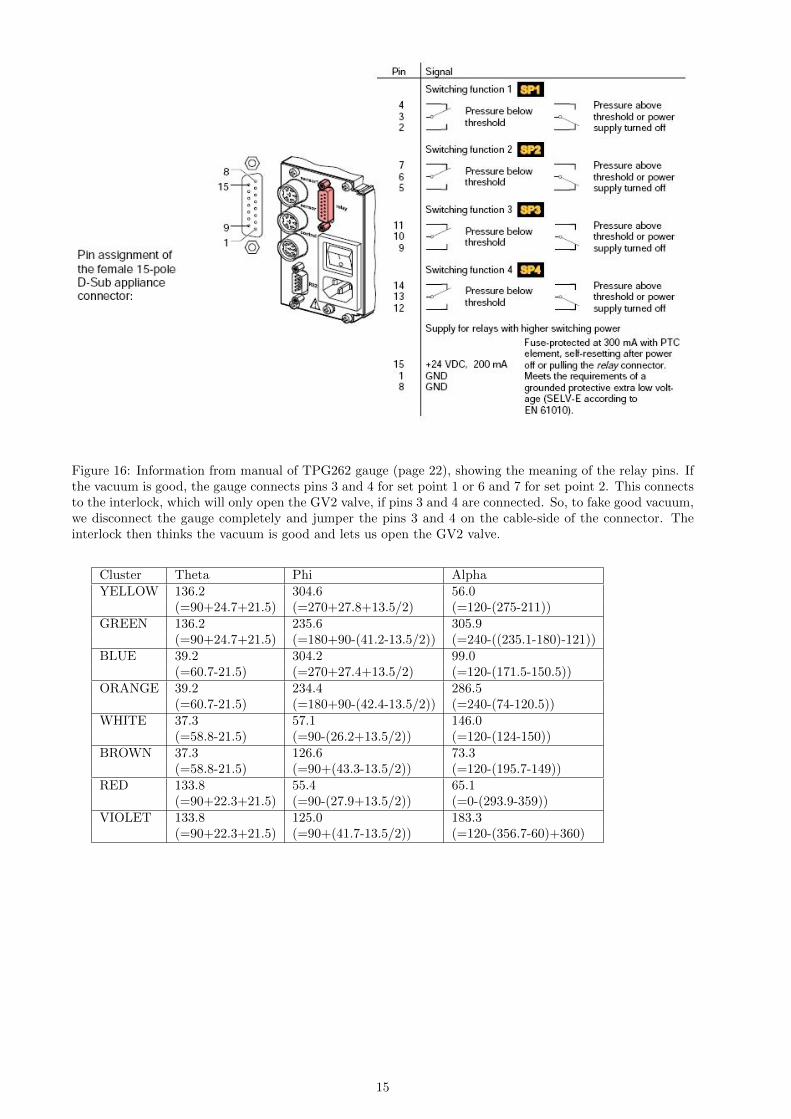
Figure 16: Information from manual of TPG262 gauge (page 22), showing the meaning of the relay pins. Ifthe vacuum is good, the gauge connects pins 3 and 4 for set point 1 or 6 and 7 for set point 2. This connectsto the interlock, which will only open the GV2 valve, if pins 3 and 4 are connected. So, to fake good vacuum,we disconnect the gauge completely and jumper the pins 3 and 4 on the cable-side of the connector. Theinterlock then thinks the vacuum is good and lets us open the GV2 valve.
Cluster Theta Phi AlphaYELLOW 136.2 304.6 56.0
(=90+24.7+21.5) (=270+27.8+13.5/2) (=120-(275-211))GREEN 136.2 235.6 305.9
(=90+24.7+21.5) (=180+90-(41.2-13.5/2)) (=240-((235.1-180)-121))BLUE 39.2 304.2 99.0
(=60.7-21.5) (=270+27.4+13.5/2) (=120-(171.5-150.5))ORANGE 39.2 234.4 286.5
(=60.7-21.5) (=180+90-(42.4-13.5/2)) (=240-(74-120.5))WHITE 37.3 57.1 146.0
(=58.8-21.5) (=90-(26.2+13.5/2)) (=120-(124-150))BROWN 37.3 126.6 73.3
(=58.8-21.5) (=90+(43.3-13.5/2)) (=120-(195.7-149))RED 133.8 55.4 65.1
(=90+22.3+21.5) (=90-(27.9+13.5/2)) (=0-(293.9-359))VIOLET 133.8 125.0 183.3
(=90+22.3+21.5) (=90+(41.7-13.5/2)) (=120-(356.7-60)+360)
15