minimally invasive tka profix™ distal cut first · laterally leaving a small amount of fat deep...
TRANSCRIPT
Surgical Technique INNOVATIONS IN MINIMALLY INVASIVEJOINT SURGERY
Minimally Invasive TKAPROFIX™ Distal Cut First

Femoral Sizing Guide7151-3311
Femoral Sizing Stylus7151-3346
Femoral Anterior Referencing Stylus7151-3313
Valgus Collet5° Valgus 0° Flex Collet 7151-33375° Valgus 4° Flex Collet (Right) 7151-33325° Valgus 4° Flex Collet (Left) 7151-3333
External Rotation PaddleLeft 7151-3342Right 7151-3343Neutral 7151-3344
Paddle Alignment Guide7151-3345
Minimally Invasive Instrument Tray7151-3361
Minimally Invasive Cutting Block Tray7151-3362
Valgus Alignment GuideRight 7151-3338Left 7151-3339
Distal Resection StylusLeft 7151-3328Right 7151-3329
Distal Resection Block7151-3340
Tibial Cutting Block (Left)4° 7151-3322 0° 7151-3324 7° 7151-3326
Tibial Cutting Block (Right)4° 7151-3323 0° 7151-3325 7° 7151-3327
Instruments
Femoral Cutting BlockSize 1 7151-3314Size 2 7151-3315Size 3 7151-3316Size 4 7151-3317
Size 5 7151-3318Size 6 7151-3319Size 7 7151-3320
Quick Release Handle7151-2460
1
Instruments . . . . . . . . . . . . . . . . . . . . . . . . . . . . . . . . . . . . . . . . . . IFC
Introduction . . . . . . . . . . . . . . . . . . . . . . . . . . . . . . . . . . . . . . . . . . . .2Leg PositionIncisionArthrotomyExposure
Femoral Preparation . . . . . . . . . . . . . . . . . . . . . . . . . . . . . . .3, 4, 5, 6SizingDistal Cutting Assembly and ResectionFemoral Resection – Anterior ReferencingFemoral Resection – Posterior Referencing
Tibial Preparation . . . . . . . . . . . . . . . . . . . . . . . . . . . . . . . . . . . . . 7, 8Intramedullary Tibial Alignment and Proximal Tibial ResectionExtramedullary Tibial Alignment and Proximal Tibial Resection
Tibial and Femoral Preparation . . . . . . . . . . . . . . . . . . . . . . . . . . . . 9
Knee Alignment Assessment . . . . . . . . . . . . . . . . . . . . . . . . . . . . 10
Patellar Preparation . . . . . . . . . . . . . . . . . . . . . . . . . . . . . . . . . . 11, 12Inset TechniqueOnset Technique
Posterior Stablized . . . . . . . . . . . . . . . . . . . . . . . . . . . . . . . . . . 13, 14
Implantation . . . . . . . . . . . . . . . . . . . . . . . . . . . . . . . . . . . . . . . .15, 16Tibial ImplantationFemoral ImplantationPatellar ImplantationClosure
Leo A. Whiteside, M.D. Missouri Bone & Joint CenterSt. Louis, MO
Nota Bene:The technique description herein is made available to the healthcare professional to illustrate the author’s suggested treatment for the uncomplicated procedure. In the final analysis, the preferred treatment is that which addresses the needs of the patient.

The suprapatellar pouch is identified, separatedfrom the underside of the tendon and preserved.
The distal extent of the vastus medialis (VMO) is identified and the orientation of the fibers is determined. An oblique cut is made to the VMOand the muscle fibers are then spread bluntly forapproximately 2cm (Figure 1).
ExposureWith the leg extended, the patella is retracted laterally. The fat pad is excised both medially andlaterally leaving a small amount of fat deep underthe patellar tendon. The patellar tendon proximal tothe tubercle is dissected from the tibia. At this point,release of the anterior horn of the lateral meniscuswill facilitate reflection of the mechanism to thelateral side. The anterior horn of the medialmeniscus is divided and dissection is carried around the proximal medial tibia usingelectrocautery and a box osteotome.
A thin bent Hohmann is placed into the lateral sideto hold the patella in a subluxed position while asecond Hohmann or a Z-retractor is placed alongthe medial border of the proximal tibia to protectthe medial collateral ligament (Figure 2).
Tip: Excessive tension on the retractors is notnecessary and can sometimes hamper the exposure.
The proximal soft tissue attachments extendingaround the proximal medial tibia are released in thestandard fashion. Finally, divide and excise theanterior cruciate ligament if present.
Tip: In patients with a tight extensor mechanism(usually larger, muscular patients or those withabundant patellar osteophytes), the patella is cut at this time (see page 11).
2
Introduction
Leg PositionAppropriate leg position is crucial when performingminimally invasive total knee arthroplasty. During the procedure, the knee is flexed to 70-90°.Hyperflexion is used only intermittently for specificportions of the case, such as insertion of the tibialcomponent. To aid in holding the leg, a sandbag isplaced across from the contralateral ankle whenpositioning the patient on the table.
IncisionWith the leg fully extended, a longitudinal incisionmeasuring 9.5 to 12 centimeters (33/4 to 43/4 inches)is made over the anterior aspect of the knee alongthe medial border of the patella. The incisionextends approximately from the middle of the tibialtubercle to a point slightly proximal to the superiorpole of the patella. If significant tension is noted atthe skin edges, the incision should be extended tominimize risk of wound edge necrosis.
ArthrotomyThe procedure can be performed using a “mini-patellar” capsulotomy or a “mini-midvastus”capsulotomy. The midvastus may offer someadvantages for quicker recovery of extensorfunction postoperatively. However, in cases wherethe extensor mechanism is stiff or the patient isheavily muscled, the parapatellar capsulotomy mayallow easier mobilization of the patella. Either typeof arthrotomy can be extended to conventionallength if exposure is problematic.
For the mini midvastus approach, begin 5mmmedial to the tibial tubercle and extend dissectionaround the medial border of the patella. Thearthrotomy is extended up to the proximal borderof the patella.
Figure 1 Figure 2
Sizing
1. Flex the knee 70-90°.
2. Place a thin bent Hohmann retractor laterallyaround the tibia and retract the patella laterally(not everted).
3. Divide and excise the ACL and the anterior hornof the lateral meniscus.
4. Identify the rotational reference landmarks• A-P axis (Whiteside's Line)• Medial/lateral posterior femoral condyles• Epicondylar axis.
5. Using the Femoral 3/8" Drill, make a hole anteriorto the posterior cruciate ligament attachment. Thisdrill is easily attached to power equipment usingthe Power Quick Connect. The resulting starterhole is larger than the 8mm Reamer Rod. Aspiratethe canal thoroughly with a long suction cannula.
6. Attach the T-Handle Quick Connect to the 8mm Reamer Rod and slowly insert into thefemoral canal.
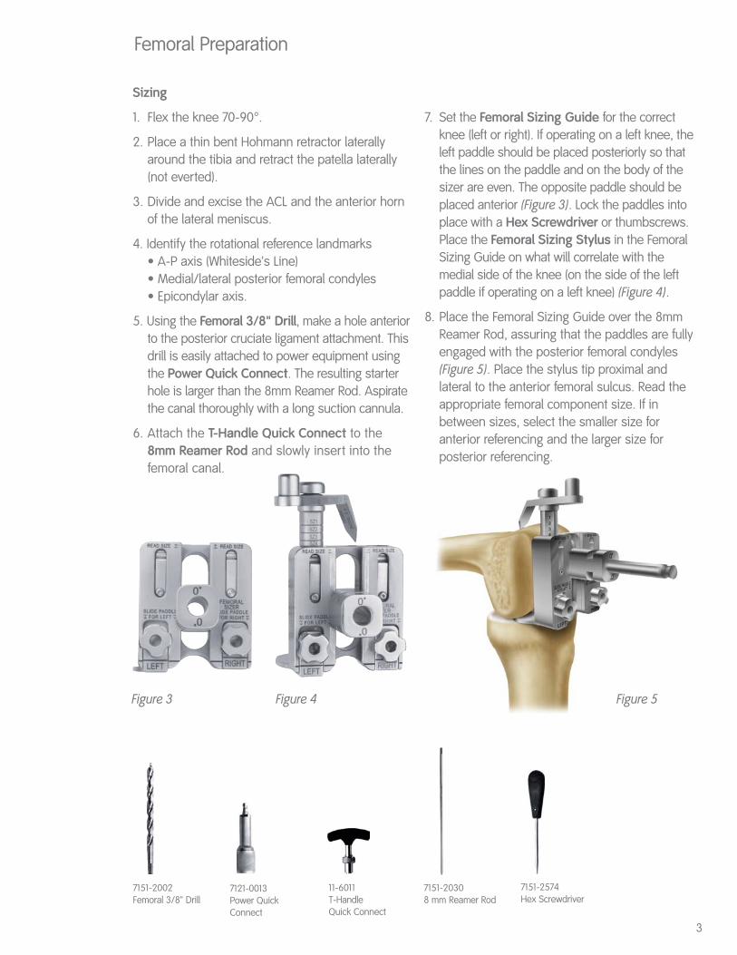
7. Set the Femoral Sizing Guide for the correctknee (left or right). If operating on a left knee, theleft paddle should be placed posteriorly so thatthe lines on the paddle and on the body of thesizer are even. The opposite paddle should beplaced anterior (Figure 3). Lock the paddles intoplace with a Hex Screwdriver or thumbscrews.Place the Femoral Sizing Stylus in the FemoralSizing Guide on what will correlate with themedial side of the knee (on the side of the leftpaddle if operating on a left knee) (Figure 4).
8. Place the Femoral Sizing Guide over the 8mmReamer Rod, assuring that the paddles are fullyengaged with the posterior femoral condyles(Figure 5). Place the stylus tip proximal andlateral to the anterior femoral sulcus. Read theappropriate femoral component size. If inbetween sizes, select the smaller size foranterior referencing and the larger size forposterior referencing.
3
Femoral Preparation
7121-0013Power QuickConnect
7151-20308 mm Reamer Rod
7151-2002Femoral 3/8" Drill
11-6011T-Handle Quick Connect
Figure 3 Figure 4
7151-2574Hex Screwdriver
Figure 5
Femoral Preparation (Continued)
Distal Cutting Assembly and Resection
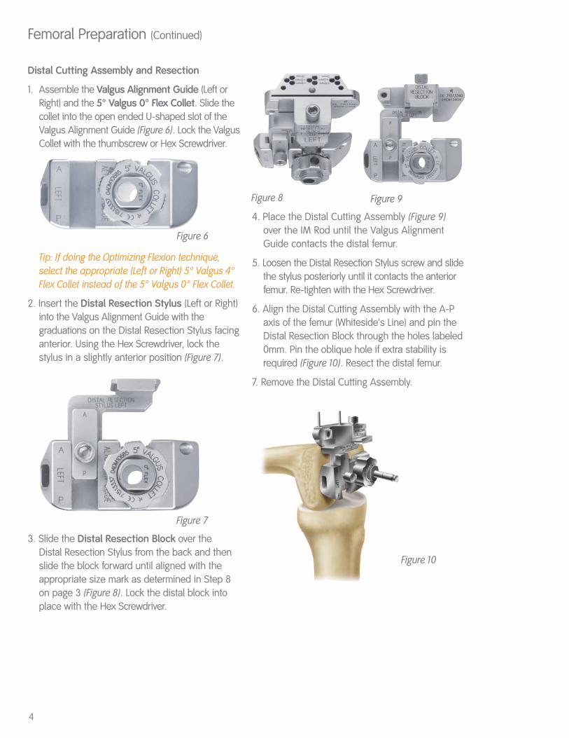
1. Assemble the Valgus Alignment Guide (Left orRight) and the 5° Valgus 0° Flex Collet. Slide thecollet into the open ended U-shaped slot of theValgus Alignment Guide (Figure 6). Lock the ValgusCollet with the thumbscrew or Hex Screwdriver.
Tip: If doing the Optimizing Flexion technique,select the appropriate (Left or Right) 5° Valgus 4°Flex Collet instead of the 5° Valgus 0° Flex Collet.
2. Insert the Distal Resection Stylus (Left or Right)into the Valgus Alignment Guide with thegraduations on the Distal Resection Stylus facinganterior. Using the Hex Screwdriver, lock thestylus in a slightly anterior position (Figure 7).
3. Slide the Distal Resection Block over the Distal Resection Stylus from the back and thenslide the block forward until aligned with theappropriate size mark as determined in Step 8on page 3 (Figure 8). Lock the distal block intoplace with the Hex Screwdriver.
4. Place the Distal Cutting Assembly (Figure 9)over the IM Rod until the Valgus AlignmentGuide contacts the distal femur.
5. Loosen the Distal Resection Stylus screw and slidethe stylus posteriorly until it contacts the anteriorfemur. Re-tighten with the Hex Screwdriver.
6. Align the Distal Cutting Assembly with the A-Paxis of the femur (Whiteside's Line) and pin theDistal Resection Block through the holes labeled0mm. Pin the oblique hole if extra stability isrequired (Figure 10). Resect the distal femur.
7. Remove the Distal Cutting Assembly.
Figure 6
Figure 7
Figure 10
Figure 8 Figure 9
4

Femoral Preparation (Continued)
Femoral Resection - Anterior Referencing
1. Choose the correct size Femoral Cutting Block.
2. Attach the Femoral Anterior Referencing Stylusto the appropriate Femoral Cutting Block (Figure 11).
3. Place the Femoral Cutting Block on the distalfemur (Figure 12). Allow the stylus to rest proximaland lateral to the anterior femoral sulcus. Theblock should be rotated so that the central A-Paxis lines up with Whiteside's Line on the femur.
Tip: If doing the Optimizing Flexion technique, alignthe appropriate sizing mark on the stylus arm withthe back of the Femoral Anterior Referencing Stylusbefore locking into place.
Tip: External Rotation Paddles may be used forrotational alignment of the Femoral Cutting Block, ifdesired. Secure the Paddle Alignment Guide to theFemoral Cutting Block using the thumbscrew orHex Screwdriver (Figure 13). Attach the ExternalRotation Paddle to the Paddle Alignment Guideleaving it free to move A-P by leaving thethumbscrew loose (Figures 14 and 15).
4. Pin the Femoral Cutting Block to the distal femurthrough the attachment holes on the medial andlateral sides of the cutting block.
5. Perform the femoral resections as follows: (1)Posterior, (2) Posterior Chamfer, (3) Anterior, and (4) Anterior Chamfer.
Figure 11
Figure 12
5

Femoral Resection - Posterior Referencing
1. Choose the correct size Femoral Cutting Block.
2. Attach the Paddle Alignment Guide into theappropriate Femoral Cutting Block (Figure 13).Lock the Paddle Alignment Guide into place withthe thumbscrew or a Hex Screwdriver.
3. Place the External Rotation Paddle (Right, Left orNeutral) over the free end of the Paddle AlignmentGuide. Move the External Rotation Paddleanteriorly until the bearings engage in the grooveon the Paddle Alignment Guide (Figures 14 and 15).Lock the External Rotation Guide into place withthe thumbscrew or a Hex Screwdriver.
Tip: If doing the Optimizing Flexion Technique,follow the arrow (pointing anteriorly and marked“4º Flexion”) on the side of the Paddle AlignmentGuide and move the External Rotation Paddleanteriorly until the paddle is flush with the bottomof the Femoral Cutting Block. Lock the ExternalRotation Guide into place with the thumbscrew ora Hex Screwdriver.
4. Place the Femoral Cutting Block on the distal femur, assuring contact between theExternal Rotation Paddle and the posteriorfemoral condyles (Figure 16).
5. Use the Femoral Anterior Referencing Stylusto check anterior position to avoid notching. If notching is evident, select a larger size cuttingblock or loosen paddles to allow the block toslide anterior to prevent notching.
6. Pin the Femoral Cutting Block to the distal femurthrough the attachment holes on the medial andlateral sides of the cutting block.
7. Remove the External Rotation Paddle and PaddleAlignment Guide by loosening the thumbscrewon the Paddle Alignment Guide.
8. Perform the femoral resections as follows: (1) Posterior, (2) Posterior Chamfer, (3) Anterior,and (4) Anterior Chamfer.
Tip: Downsizing Procedure:If downsizing is required after completion of thefemoral cuts, align the anterior slot on the FemoralCutting Block of the next size down to the level ofthe previous anterior cut (a blade can be insertedthrough the anterior slot and the blade can rest onthe anterior cut). Pin the Femoral Cutting Block.Redo the Posterior, Posterior Chamfer and AnteriorChamfer cuts.
6
Femoral Preparation (Continued)
Figure 13
Figure 14 Figure 15
Figure 16
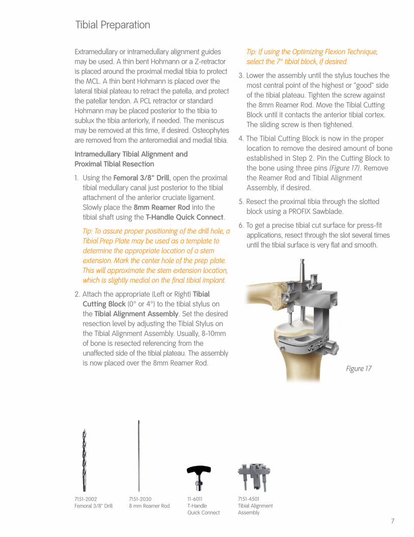
Extramedullary or intramedullary alignment guidesmay be used. A thin bent Hohmann or a Z-retractoris placed around the proximal medial tibia to protectthe MCL. A thin bent Hohmann is placed over thelateral tibial plateau to retract the patella, and protectthe patellar tendon. A PCL retractor or standardHohmann may be placed posterior to the tibia tosublux the tibia anteriorly, if needed. The meniscusmay be removed at this time, if desired. Osteophytesare removed from the anteromedial and medial tibia.
Intramedullary Tibial Alignment and Proximal Tibial Resection
1. Using the Femoral 3/8" Drill, open the proximaltibial medullary canal just posterior to the tibialattachment of the anterior cruciate ligament.Slowly place the 8mm Reamer Rod into thetibial shaft using the T-Handle Quick Connect.
Tip: To assure proper positioning of the drill hole, aTibial Prep Plate may be used as a template todetermine the appropriate location of a stemextension. Mark the center hole of the prep plate.This will approximate the stem extension location,which is slightly medial on the final tibial implant.
2. Attach the appropriate (Left or Right) TibialCutting Block (0° or 4°) to the tibial stylus onthe Tibial Alignment Assembly. Set the desiredresection level by adjusting the Tibial Stylus onthe Tibial Alignment Assembly. Usually, 8-10mmof bone is resected referencing from theunaffected side of the tibial plateau. The assemblyis now placed over the 8mm Reamer Rod.
Tip: If using the Optimizing Flexion Technique,select the 7° tibial block, if desired.
3. Lower the assembly until the stylus touches themost central point of the highest or "good" sideof the tibial plateau. Tighten the screw againstthe 8mm Reamer Rod. Move the Tibial CuttingBlock until it contacts the anterior tibial cortex.The sliding screw is then tightened.
4. The Tibial Cutting Block is now in the properlocation to remove the desired amount of boneestablished in Step 2. Pin the Cutting Block tothe bone using three pins (Figure 17). Removethe Reamer Rod and Tibial AlignmentAssembly, if desired.
5. Resect the proximal tibia through the slottedblock using a PROFIX Sawblade.
6. To get a precise tibial cut surface for press-fitapplications, resect through the slot several timesuntil the tibial surface is very flat and smooth.
Tibial Preparation
7
7151-20308 mm Reamer Rod
7151-2002Femoral 3/8" Drill
11-6011T-Handle Quick Connect
7151-4501Tibial AlignmentAssembly
Figure 17
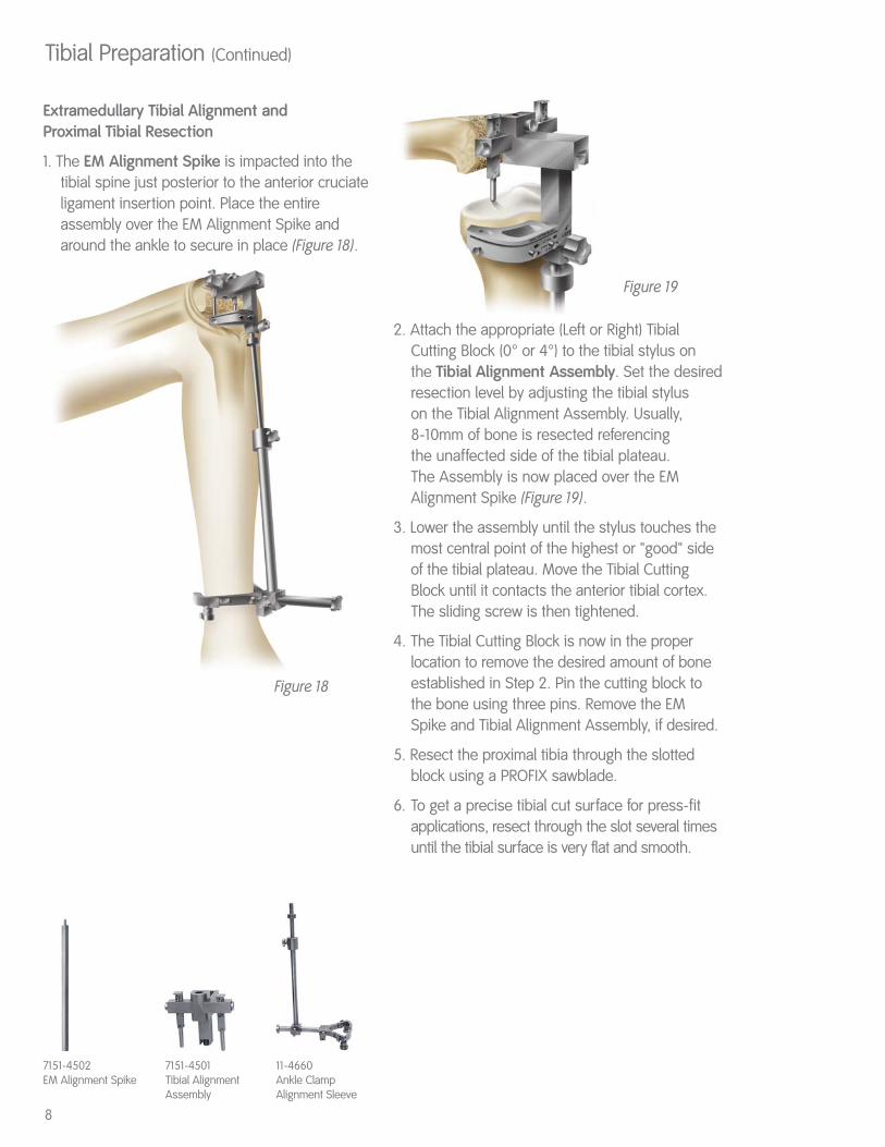
Extramedullary Tibial Alignment and Proximal Tibial Resection
1. The EM Alignment Spike is impacted into thetibial spine just posterior to the anterior cruciateligament insertion point. Place the entireassembly over the EM Alignment Spike andaround the ankle to secure in place (Figure 18).
2. Attach the appropriate (Left or Right) TibialCutting Block (0° or 4°) to the tibial stylus on the Tibial Alignment Assembly. Set the desiredresection level by adjusting the tibial styluson the Tibial Alignment Assembly. Usually, 8-10mm of bone is resected referencing the unaffected side of the tibial plateau. The Assembly is now placed over the EMAlignment Spike (Figure 19).
3. Lower the assembly until the stylus touches themost central point of the highest or "good" sideof the tibial plateau. Move the Tibial CuttingBlock until it contacts the anterior tibial cortex.The sliding screw is then tightened.
4. The Tibial Cutting Block is now in the properlocation to remove the desired amount of boneestablished in Step 2. Pin the cutting block tothe bone using three pins. Remove the EM Spike and Tibial Alignment Assembly, if desired.
5. Resect the proximal tibia through the slottedblock using a PROFIX sawblade.
6. To get a precise tibial cut surface for press-fitapplications, resect through the slot several timesuntil the tibial surface is very flat and smooth.
8
Tibial Preparation (Continued)
7151-4502EM Alignment Spike
Figure 18
Figure 19
7151-4501Tibial AlignmentAssembly
11-4660Ankle ClampAlignment Sleeve
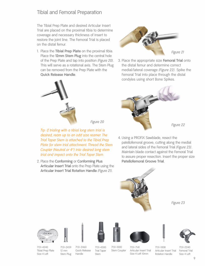
The Tibial Prep Plate and desired Articular InsertTrial are placed on the proximal tibia to determinecoverage and necessary thickness of insert torestore the joint line. The Femoral Trial is placedon the distal femur.
1. Place the Tibial Prep Plate on the proximal tibia.Place the 12mm Stem Plug into the central holeof the Prep Plate and tap into position (Figure 20).This will serve as a rotational axis. The Stem Plugcan be removed from the Prep Plate with theQuick Release Handle.
Tip: If trialing with a tibial long stem trial isdesired, ream up to an odd size reamer. TheTrial Taper Stem is attached to the Tibial PrepPlate for stem trial attachment. Thread the StemCoupler (Neutral or 4°) into desired long stemtrial and impact onto the Trial Taper Stem.
2. Place the Conforming or Conforming PlusArticular Insert Trial onto the Prep Plate using theArticular Insert Trial Rotation Handle (Figure 21).
3. Place the appropriate size Femoral Trial ontothe distal femur and determine correctmedial/lateral coverage (Figure 22). Spike theFemoral Trial into place through the distalcondyles using short Bone Spikes.
4. Using a PROFIX Sawblade, resect thepatellofemoral groove, cutting along the medialand lateral sides of the Femoral Trial (Figure 23).Maintain blade contact against the Femoral Trialto assure proper resection. Insert the proper sizePatellofemoral Groove Trial.
Tibial and Femoral Preparation
7151-4240Tibial Prep Plate Size 4 Left
7151-245912 mm Stem Plug
7151-1008Articular Insert TrialRotation Handle
7151-2460Quick ReleaseHandle
7151-4300Trial Taper Stem
7151-1000Stem Coupler
Figure 20
Figure 21
Figure 22
Figure 23
7151-7141Articular Insert TrialSize 4 Left 10mm
7151-2240Femoral TrialSize 4 Left
9

Alignment of the knee is assessed with thefemoral and tibial trials in place. The Tibial PrepPlate is rotated to assure that the line on theinsert matches with the line on the PatellofemoralGroove Trial with the knee in full extension.
1. In full extension, assess the alignment of trials andevaluate range of motion.
2. Insert the Articular Insert Trial Rotation Handle intothe anterior slot on the Articular Insert Trial. Rotatethe handle until the lines on the Femoral andTibial Trials are perfectly aligned (Figure 24).
3. With the knee in full extension, align the markson the Insert Trial and Femoral Trial to assureproper rotational alignment. Using a cauterypencil, mark the tibia below the alignmentmarkers on the Tibial Prep Plate. When using aNonporous Tibial Implant, remove the ArticularInsert Trial and prepare for the distal fins on theimplant using the appropriate Nonporous TibialFin Punch, All-Poly Tibial Fin Punch, or TibialKeel Stem Punch (Figure 25). To prevent the
Prep Plate from shifting while using the punch, it is recommended to pin the Prep Plate in placethrough the anterior spike holes. If using theI-beam stem, use the appropriate size NonporousTibial Fin Punch, then remove the prep plate.Place the I-beam stem punch on the proximaltibia by inserting the fins of the punch into theprepared fin slots, then punch.
Tip: The Tibial Keel Stem Punch is designed to be used with PROFIX Tibial Implants sizes 3-7. When using a Size 1 or 2 PROFIX Tibial Implant, it isrecommended to use the 14mm Metaphyseal Stem.
Knee Alignment Assessment
7151-4517Nonporous Tibial Fin Punch Size 3-4
7151-4607All-Poly Tibial Fin Punch
7151-4621Tibial Keel Stem Punch
Figure 24
Figure 25
7151-2740PatellofemoralGroove Trial Size 4
10
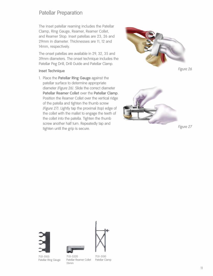
The inset patellar reaming includes the PatellarClamp, Ring Gauge, Reamer, Reamer Collet, and Reamer Stop. Inset patellas are 23, 26 and 29mm in diameter. Thicknesses are 11, 12 and14mm, respectively.
The onset patellas are available in 29, 32, 35 and39mm diameters. The onset technique includes thePatellar Peg Drill, Drill Guide and Patellar Clamp.
Inset Technique
1. Place the Patellar Ring Gauge against thepatellar surface to determine appropriatediameter (Figure 26). Slide the correct diameterPatellar Reamer Collet over the Patellar Clamp.Position the Reamer Collet over the vertical ridgeof the patella and tighten the thumb screw(Figure 27). Lightly tap the proximal (top) edge ofthe collet with the mallet to engage the teeth ofthe collet into the patella. Tighten the thumbscrew another half turn. Repeatedly tap andtighten until the grip is secure.
Patellar Preparation
11
7151-5103Patellar Ring Gauge
7151-5320Patellar Reamer Collet26mm
Figure 26
Figure 27
7151-5100Patellar Clamp
Patellar Preparation (Continued)
Inset Technique (Continued)
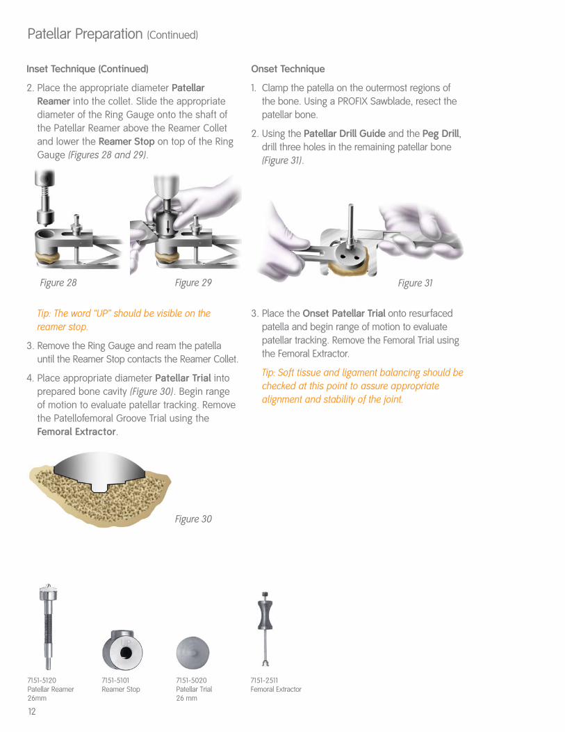
2. Place the appropriate diameter PatellarReamer into the collet. Slide the appropriatediameter of the Ring Gauge onto the shaft ofthe Patellar Reamer above the Reamer Colletand lower the Reamer Stop on top of the RingGauge (Figures 28 and 29).
Tip: The word “UP” should be visible on thereamer stop.
3. Remove the Ring Gauge and ream the patellauntil the Reamer Stop contacts the Reamer Collet.
4. Place appropriate diameter Patellar Trial intoprepared bone cavity (Figure 30). Begin rangeof motion to evaluate patellar tracking. Removethe Patellofemoral Groove Trial using theFemoral Extractor.
Onset Technique
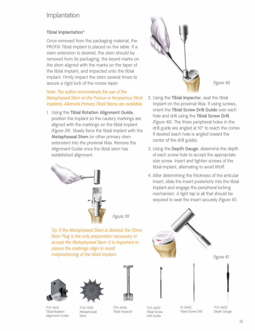
1. Clamp the patella on the outermost regions ofthe bone. Using a PROFIX Sawblade, resect thepatellar bone.
2. Using the Patellar Drill Guide and the Peg Drill,drill three holes in the remaining patellar bone(Figure 31).
3. Place the Onset Patellar Trial onto resurfacedpatella and begin range of motion to evaluatepatellar tracking. Remove the Femoral Trial usingthe Femoral Extractor.
Tip: Soft tissue and ligament balancing should bechecked at this point to assure appropriatealignment and stability of the joint.
12
Figure 31
Figure 30
Figure 28 Figure 29
7151-5120Patellar Reamer26mm
7151-5101Reamer Stop
7151-5020Patellar Trial 26 mm
7151-2511Femoral Extractor

Posterior Stabilized
This portion of the technique will prepare the femurfor the femoral housing of the PS implant.Instruments required for this procedure include thePS Positioner, PS Box Reamer Guide, PS BoxReamer, PS Box Chisel Guide, PS Box Chisel, andthe PS Femoral Trial.
1. Make all femoral and tibial cuts in the mannerdescribed on pages 3-8.
2. Place the appropriate size Femoral Trial onto thedistal femur and determine correct medial/lateralcoverage. Spike Femoral Trial into place throughdistal condyles using short Bone Spikes. Using aPROFIX Sawblade, resect the patellofemoralgroove, cutting along the medial and lateral sidesof the Femoral Trial. Maintain blade contactagainst the Femoral Trial to assure properresection. Then remove the Femoral Trial.
3. Attach the PS Positioner (Figure 32) referencingoff the femoral spike holes (which were alreadycreated by the Femoral Trial) or use the AnteriorChamfer and distal cut intersection. Predrill andpin the PS Positioner with bone spikes.
Note: If desired, the Quick Release Handle may beattached to the PS Positioner.
4. With the thumb screws on the PS Positioner loose,place the PS Box Reamer Guide (Figure 33) intothe Positioner, then tighten the thumb screw tofirmly hold the Reamer Guide in place. Proceed toream through both holes with the PS Box Reamer(Figure 34). This will prepare the majority of thefemoral housing area.
5. Loosen the positioner thumb screw and removethe Reamer Guide. Place the PS Box ChiselGuide into the Positioner and tighten thethumb screw firmly to hold the Chisel Guide inplace. Attach the Fin Punch Handle to the PSBox Chisel and impact the PS Box Chisel(Figure 35) through the Box Chisel Guide. Thiswill complete the bone resection for the PSfemoral housing.
7151-2462PS Positioner
7151-2464PS Box ReamerGuide
7151-2463PS Box Chisel Guide
7151-4515Fin Punch Handle
7151-2465PS Box Reamer
7151-2466PS Box Chisel
Figure 32
Figure 35
Figure 33 Figure 34
13

Posterior Stabilized (Continued)
6. Remove the positioner and assemble the PSFemoral Trial. Place the Primary Femoral TrialModule (without taper) into the appropriate sizetrial and tighten one of the module lugs with animplant screwdriver. After one turn, tighten theother lug one turn, and alternate until the moduleis seated in the trial (Figure 36). Place the PSFemoral Trial onto the distal femur (Figure 37). Donot directly impact the trial on the anteromedialor anterolateral flanges. Impacting these areascould deform the anterior cutting slots.
7. After evaluating the range of motion with Femoraland Tibial Trials, implant the PS Femoral Implantin the distal femur. Implant the Tibial and the PSArticular Insert. Assess range of motion for thefinal implants (Figure 38).
7151-2476Primary Femoral Trial Modulewithout Taper
7151-2242PS Femoral Trial
Figure 36
Figure 37
Figure 38
14
Tibial Implantation*
Once removed from the packaging material, thePROFIX Tibial Implant is placed on the table. If astem extension is desired, the stem should beremoved from its packaging, the keyed marks onthe stem aligned with the marks on the taper ofthe tibial implant, and impacted onto the tibialimplant. Firmly impact the stem several times toassure a rigid lock of the morse taper.
Note: The author recommends the use of theMetaphyseal Stem on the Porous or Nonporous TibialImplants. Alternate Primary Tibial Stems are available.
1. Using the Tibial Rotation Alignment Guide,position the implant so the cautery markings arealigned with the markings on the tibial implant(Figure 39). Slowly force the tibial implant with theMetaphyseal Stem (or other primary stemextension) into the proximal tibia. Remove theAlignment Guide once the tibial stem hasestablished alignment.
Tip: If the Metaphyseal Stem is desired, the 12mmStem Plug is the only preparation necessary toaccept the Metaphyseal Stem. It is important toassure the markings align to avoidmalpositioning of the tibial implant.
Implantation
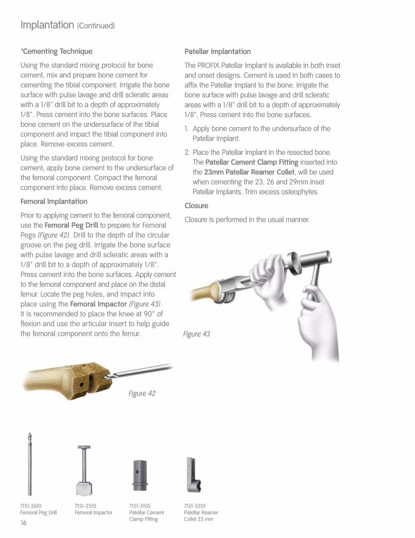
2. Using the Tibial Impactor, seat the tibialimplant on the proximal tibia. If using screws,orient the Tibial Screw Drill Guide over eachhole and drill using the Tibial Screw Drill(Figure 40). The three peripheral holes in thedrill guide are angled at 10° to reach the cortexif desired (each hole is angled toward thecenter of the drill guide).
3. Using the Depth Gauge, determine the depthof each screw hole to accept the appropriatesize screw. Insert and tighten screws of thetibial implant, alternating to avoid liftoff.
4. After determining the thickness of the articularinsert, slide the insert posteriorly into the tibialimplant and engage the peripheral lockingmechanism. A light tap is all that should berequired to seat the insert securely (Figure 41).
7151-4601Tibial RotationAlignment Guide
7151-4603Tibial ScrewDrill Guide
21-0442Tibial Screw Drill
7151-4602Depth Gauge
7151-4606Tibial Impactor
7150-1020MetaphysealStem
Figure 39
Figure 40
Figure 41
15
*Cementing Technique
Using the standard mixing protocol for bonecement, mix and prepare bone cement forcementing the tibial component. Irrigate the bonesurface with pulse lavage and drill scleratic areaswith a 1/8" drill bit to a depth of approximately 1/8". Press cement into the bone surfaces. Place bone cement on the undersurface of the tibialcomponent and impact the tibial component intoplace. Remove excess cement.
Using the standard mixing protocol for bonecement, apply bone cement to the undersurface ofthe femoral component. Compact the femoralcomponent into place. Remove excess cement.
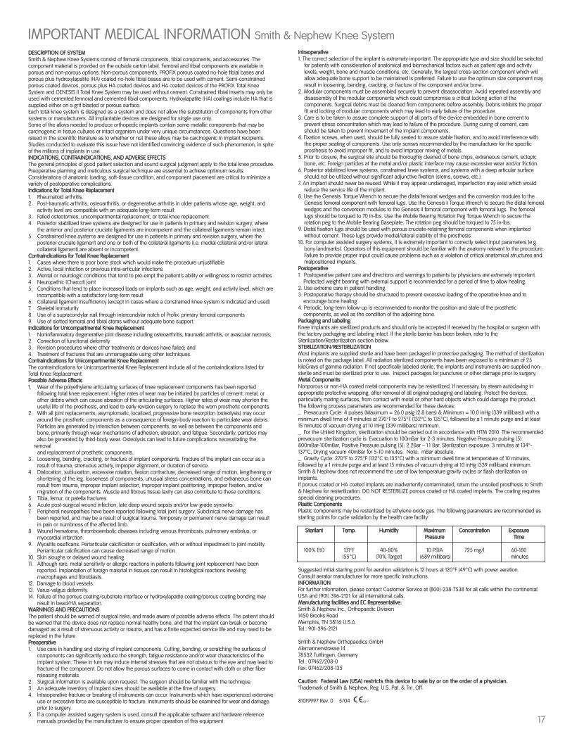
Femoral Implantation
Prior to applying cement to the femoral component,use the Femoral Peg Drill to prepare for FemoralPegs (Figure 42). Drill to the depth of the circulargroove on the peg drill. Irrigate the bone surfacewith pulse lavage and drill scleratic areas with a1/8" drill bit to a depth of approximately 1/8".Press cement into the bone surfaces. Apply cementto the femoral component and place on the distalfemur. Locate the peg holes, and impact into place using the Femoral Impactor (Figure 43). It is recommended to place the knee at 90° offlexion and use the articular insert to help guidethe femoral component onto the femur.
Patellar Implantation
The PROFIX Patellar Implant is available in both inset and onset designs. Cement is used in both cases toaffix the Patellar Implant to the bone. Irrigate thebone surface with pulse lavage and drill scleraticareas with a 1/8" drill bit to a depth of approximately1/8". Press cement into the bone surfaces.
1. Apply bone cement to the undersurface of thePatellar Implant.
2. Place the Patellar Implant in the resected bone.The Patellar Cement Clamp Fitting inserted intothe 23mm Patellar Reamer Collet, will be usedwhen cementing the 23, 26 and 29mm InsetPatellar Implants. Trim excess osteophytes.
Closure
Closure is performed in the usual manner.
Implantation (Continued)
7151-2610Femoral Peg Drill
7151-5105Patellar CementClamp Fitting
7151-5310Patellar ReamerCollet 23 mm
Figure 42
Figure 43
16
7151-2510Femoral Impactor
DESCRIPTION OF SYSTEMSmith & Nephew Knee Systems consist of femoral components, tibial components, and accessories. Thecomponent material is provided on the outside carton label. Femoral and tibial components are available inporous and non-porous options. Non-porous components, PROFIX porous coated no-hole tibial bases andporous plus hydroxylapatite (HA) coated no-hole tibial bases are to be used with cement. Semi-constrainedporous coated devices, porous plus HA coated devices and HA coated devices of the PROFIX Total KneeSystem and GENESIS II Total Knee System may be used without cement. Constrained tibial inserts may only beused with cemented fermoral and cemented tibial components. Hydroylapatite (HA) coatings include HA that issupplied either on a grit blasted or porous surface. Each total knee system is designed as a system and does not allow the substitution of components from othersystems or manufacturers. All implantable devices are designed for single use only.Some of the alloys needed to produce orthopedic implants contain some metallic components that may becarcinogenic in tissue cultures or intact organism under very unique circumstances. Questions have beenraised in the scientific literature as to whether or not these alloys may be carcinogenic in implant recipients.Studies conducted to evaluate this issue have not identified convincing evidence of such phenomenon, in spiteof the millions of implants in use.INDICATIONS, CONTRAINDICATIONS, AND ADVERSE EFFECTSThe general principles of good patient selection and sound surgical judgment apply to the total knee procedure.Preoperative planning and meticulous surgical technique are essential to achieve optimum results.Considerations of anatomic loading, soft-tissue condition, and component placement are critical to minimize avariety of postoperative complications.Indications for Total Knee Replacement1. Rheumatoid arthritis.2. Post-traumatic arthritis, osteoarthritis, or degenerative arthritis in older patients whose age, weight, and
activity level are compatible with an adequate long-term result.3. Failed osteotomies, unicompartmental replacement, or total knee replacement.4. Posterior stabilized knee systems are designed for use in patients in primary and revision surgery, where
the anterior and posterior cruciate ligaments are incompetent and the collateral ligaments remain intact.5. Constrained knee systems are designed for use in patients in primary and revision surgery, where the
posterior cruciate ligament and one or both of the collateral ligaments (i.e. medial collateral and/or lateral collateral ligament) are absent or incompetent.
Contraindications for Total Knee Replacement1. Cases where there is poor bone stock which would make the procedure unjustifiable2. Active, local infection or previous intra-articular infections3. Mental or neurologic conditions that tend to pre-empt the patient’s ability or willingness to restrict activities4. Neuropathic (Charcot) joint5. Conditions that tend to place increased loads on implants such as age, weight, and activity level, which are
incompatible with a satisfactory long-term result6. Collateral ligament insufficiency (except in cases where a constrained knee system is indicated and used)7. Skeletal immaturity8. Use of a supracondylar nail through intercondylar notch of Profix† primary femoral components9. Use of slotted femoral and tibial stems without adequate bone support.Indications for Unicompartmental Knee Replacement1. Noninflammatory degenerative joint disease including osteoarthritis, traumatic arthritis, or avascular necrosis;2. Correction of functional deformity3. Revision procedures where other treatments or devices have failed; and4. Treatment of fractures that are unmanageable using other techniques.Contraindications for Unicompartmental Knee ReplacementThe contraindications for Unicompartmental Knee Replacement include all of the contraindications listed forTotal Knee Replacement.Possible Adverse Effects1. Wear of the polyethylene articulating surfaces of knee replacement components has been reported
following total knee replacement. Higher rates of wear may be initiated by particles of cement, metal, or other debris which can cause abrasion of the articulating surfaces. Higher rates of wear may shorten the useful life of the prosthesis, and lead to early revision surgery to replace the worn prosthetic components.
2. With all joint replacements, asymptomatic, localized, progressive bone resorption (osteolysis) may occur around the prosthetic components as a consequence of foreign-body reaction to particulate wear debris. Particles are generated by interaction between components, as well as between the components and bone, primarily through wear mechanisms of adhesion, abrasion, and fatigue. Secondarily, particles may also be generated by third-body wear. Osteolysis can lead to future complications necessitating the
removal and replacement of prosthetic components.
3. Loosening, bending, cracking, or fracture of implant components. Fracture of the implant can occur as a result of trauma, strenuous activity, improper alignment, or duration of service.
4. Dislocation, subluxation, excessive rotation, flexion contracture, decreased range of motion, lengthening or shortening of the leg, looseness of components, unusual stress concentrations, and extraneous bone can result from trauma, improper implant selection, improper implant positioning, improper fixation, and/or migration of the components. Muscle and fibrous tissue laxity can also contribute to these conditions.
5. Tibia, femur, or patella fractures.6. Acute post-surgical wound infection, late deep wound sepsis and/or low-grade synovitis.7. Peripheral neuropathies have been reported following total joint surgery. Subclinical nerve damage has
been reported, and may be a result of surgical trauma. Temporary or permanent nerve damage can result in pain or numbness of the affected limb.
8. Wound hematoma, thromboembolic diseases including venous thrombosis, pulmonary embolus, or myocardial infarction.
9. Myositis ossificans. Periarticular calcification or ossification, with or without impediment to joint mobility. Periarticular calcification can cause decreased range of motion.
10. Skin sloughs or delayed wound healing.11. Although rare, metal sensitivity or allergic reactions in patients following joint replacement have been
reported. Implantation of foreign material in tissues can result in histological reactions involving macrophages and fibroblasts.
12. Damage to blood vessels.13. Varus-valgus deformity.14. Failure of the porous coating/substrate interface or hydroxylapatite coating/porous coating bonding may
result in bead/HA separation.WARNINGS AND PRECAUTIONSThe patient should be warned of surgical risks, and made aware of possible adverse effects. The patient shouldbe warned that the device does not replace normal healthy bone, and that the implant can break or becomedamaged as a result of strenuous activity or trauma, and has a finite expected service life and may need to bereplaced in the future.Preoperative1. Use care in handling and storing of implant components. Cutting, bending, or scratching the surfaces of
components can significantly reduce the strength, fatigue resistance and/or wear characteristics of the implant system. These in turn may induce internal stresses that are not obvious to the eye and may lead to fracture of the component. Do not allow the porous surfaces to come in contact with cloth or other fiber releasing materials.
2. Surgical information is available upon request. The surgeon should be familiar with the technique.3. An adequate inventory of implant sizes should be available at the time of surgery.4. Intraoperative fracture or breaking of instruments can occur. Instruments which have experienced extensive
use or excessive force are susceptible to fracture. Instruments should be examined for wear and damage prior to surgery.
5. If a computer assisted surgery system is used, consult the applicable software and hardware reference manuals provided by the manufacturer to ensure proper operation of this equipment.
IMPORTANT MEDICAL INFORMATION Smith & Nephew Knee SystemIntraoperative1. The correct selection of the implant is extremely important. The appropriate type and size should be selected
for patients with consideration of anatomical and biomechanical factors such as patient age and activitylevels, weight, bone and muscle conditions, etc. Generally, the largest cross-section component which willallow adequate bone support to be maintained is preferred. Failure to use the optimum size component mayresult in loosening, bending, cracking, or fracture of the component and/or bone.
2. Modular components must be assembled securely to prevent disassociation. Avoid repeated assembly anddisassembly of the modular components which could compromise a critical locking action of thecomponents. Surgical debris must be cleaned from components before assembly. Debris inhibits the properfit and locking of modular components which may lead to early failure of the procedure.
3. Care is to be taken to assure complete support of all parts of the device embedded in bone cement toprevent stress concentration which may lead to failure of the procedure. During curing of cement, careshould be taken to prevent movement of the implant components.
4. Fixation screws, when used, should be fully seated to assure stable fixation, and to avoid interference withthe proper seating of components. Use only screws recommended by the manufacturer for the specificprosthesis to avoid improper fit, and to avoid improper mixing of metals.
5. Prior to closure, the surgical site should be thoroughly cleaned of bone chips, extraneous cement, ectopicbone, etc. Foreign particles at the metal and/or plastic interface may cause excessive wear and/or friction.
6. Posterior stabilized knee systems, constrained knee systems, and systems with a deep articular surfaceshould not be utilized without significant adjunctive fixation (stems, screws, etc.).
7. An implant should never be reused. While it may appear undamaged, imperfection may exist which wouldreduce the service life of the implant.
8. Use the Genesis† Torque Wrench to secure the distal femoral wedges and the conversion modules to theGenesis femoral component with femoral lugs. Use the Genesis II Torque Wrench to secure the distal femoralwedges and the conversion modules to the Genesis II femoral component with femoral lugs. The femorallugs should be torqued to 70 in-lbs. Use the Mobile Bearing Rotation Peg Torque Wrench to secure therotation peg to the Mobile Bearing Baseplate. The rotation peg should be torqued to 75 in-lbs.
9. Distal fixation lugs should be used with porous cruciate-retaining femoral components when implantedwithout cement. These lugs provide medial/lateral stability of the prosthesis.
10. For computer assisted surgery systems, it is extremely important to correctly select input parameters (e.g.bony landmarks). Operators of this equipment should be familiar with the anatomy relevant to the procedure.Failure to provide proper input could cause problems such as a violation of critical anatomical structures andmalpositioned implants.
Postoperative1. Postoperative patient care and directions and warnings to patients by physicians are extremely important.
Protected weight bearing with external support is recommended for a period of time to allow healing.2. Use extreme care in patient handling.3. Postoperative therapy should be structured to prevent excessive loading of the operative knee and to
encourage bone healing.4. Periodic, long-term follow-up is recommended to monitor the position and state of the prosthetic
components, as well as the condition of the adjoining bone.Packaging and LabelingKnee implants are sterilized products and should only be accepted if received by the hospital or surgeon withthe factory packaging and labeling intact. If the sterile barrier has been broken, refer to theSterilization/Resterilization section below.STERILIZATION/RESTERILIZATIONMost implants are supplied sterile and have been packaged in protective packaging. The method of sterilizationis noted on the package label. All radiation sterilized components have been exposed to a minimum of 25kiloGrays of gamma radiation. If not specifically labeled sterile, the implants and instruments are supplied non-sterile and must be sterilized prior to use. Inspect packages for punctures or other damage prior to surgery.Metal ComponentsNonporous or non-HA coated metal components may be resterilized, if necessary, by steam autoclaving inappropriate protective wrapping, after removal of all original packaging and labeling. Protect the devices,particularly mating surfaces, from contact with metal or other hard objects which could damage the product.The following process parameters are recommended for these devices:_ Prevacuum Cycle: 4 pulses (Maximum = 26.0 psig (2.8 bars) & Minimum = 10.0 inHg (339 millibars)) with aminimum dwell time of 4 minutes at 270°F to 275°F (132°C to 135°C), followed by a 1 minute purge and at least15 minutes of vacuum drying at 10 inHg (339 millibars) minimum._ For the United Kingdom, sterilization should be carried out in accordance with HTM 2010. The recommendedprevacuum sterilization cycle is: Evacuation to 100mBar for 2-3 minutes, Negative Pressure pulsing (5):800mBar-100mBar, Positive Pressure pulsing (5): 2.2Bar – 1.1 Bar, Sterilization exposure: 3 minutes at 134°-137°C, Drying vacuum 40mBar for 5-10 minutes. Note: mBar absolute._ Gravity Cycle: 270°F to 275°F (132°C to 135°C) with a minimum dwell time at temperature of 10 minutes,followed by a 1 minute purge and at least 15 minutes of vacuum drying at 10 inHg (339 millibars) minimum.Smith & Nephew does not recommend the use of low temperature gravity cycles or flash sterilization onimplants.If porous coated or HA coated implants are inadvertently contaminated, return the unsoiled prosthesis to Smith& Nephew for resterilization. DO NOT RESTERILIZE porous coated or HA coated implants. The coating requiresspecial cleaning procedures.Plastic ComponentsPlastic components may be resterilized by ethylene oxide gas. The following parameters are recommended asstarting points for cycle validation by the health care facility:
Sterilant Temp. Humidity Maximum Concentration Exposure Pressure Time
100% EtO 131°F 40-80% 10 PSIA 725 mg/l 60-180(55°C) (70% Target) (689 millibars) minutes
Suggested initial starting point for aeration validation is 12 hours at 120°F (49°C) with power aeration. Consult aerator manufacturer for more specific instructions.INFORMATIONFor further information, please contact Customer Service at (800)-238-7538 for all calls within the continentalUSA and (901) 396-2121 for all international calls.Manufacturing facilities and EC Representative:Smith & Nephew Inc., Orthopaedic Division1450 Brooks Road Memphis, TN 38116 U.S.ATel.: 901-396-2121
Smith & Nephew Orthopaedics GmbHAlemannenstrasse 1478532 Tuttlingen, GermanyTel.: 07462/208-0Fax: 07462/208-135
Caution: Federal Law (USA) restricts this device to sale by or on the order of a physician.™Trademark of Smith & Nephew, Reg. U.S. Pat. & Tm. Off.
81019997 Rev. 0 5/04
17

©PROFIX patent numbers: 4950298, 5047058, 5053037, 5100408, 5514140, 5354075, 5417694 and 5549688. Additional patents pending. ™Trademark of Smith & Nephew. Reg. U.S. Pat. & TM Office. This system is intended for cemented use only.
OrthopaedicsSmith & Nephew, Inc.1450 Brooks RoadMemphis, TN 38116USA
Telephone: 1-901-396-2121Information: 1-800-821-5700Orders/Inquiries: 1-800-238-7538
40430103 7128-1257 10/04
www.smith-nephew.comwww.miknee.com