miniplex transponders with es-ps power supplies
TRANSCRIPT
MINIPLEX Transponders with ES-PS Power Supplies
* Additional listings may be applicable; contact your local Simplex product supplier for the latest status.
Features
4100ES Series MINIPLEX transponders allow remotely locatedinitiating and notification functions:
• Transponder operation is available as standard or with local modeoperation
• Communications with the host fire alarm control panel use the RemoteUnit Interface (RUI and RUI+) formats
Initiating functions include:
• Conventional initiating device circuit (IDC) support• Addressable device support including TrueAlarm analog sensor
compatibility
Notification functions include:
• Addressable strobe and horn notification using enhanced powerdelivery IDNAC SLCs
• Conventional DC notification appliance circuits including TrueAlertstrobe and horn appliances
• Emergency voice/alarm communications
Local mode operation provides:
• Default local initiating and notification operation in the event of acommunications loss with the host control panel
• Enabling of an optional Local Mode Controller with a local alarmsounder, LED status indicators, and keyswitch enabled control switches
• Support for conventional Initiating Device Circuits (IDC's), conventionalNotification Appliance Circuits (NAC's), addressable IDNet devices,addressable IDNAC notification appliances, and default output tonesfrom local amplifiers
Optional modules include:
• Digital or Analog audio riser modules for connection to system audiosignals
• Digital or analog input audio amplifiers with integral on-board NACs• Power supplies with or without battery chargers• City Connect modules and RS-232 ports for printers or maintenance
terminals• Alarm relays, auxiliary relays, additional IDC modules, and NAC
expansion modules
NEMA 1/IP30 cabinets are equipped with solid doors (platinum orred) and in one, two, or three bay sizes
Listed to:
• UL 864, Fire Detection and Control (UOJZ), Smoke Control Service(UUKL), Releasing Device Service (SYZV), Emergency Communicationand Relocation Equipment (UOQY)
• UL 1076, Proprietary Alarm Units - Burglar (APOU)• UL 2017, Process Management Equipment (QVAX), Emergency Alarm
System Control Units (FSZI)• UL 1730, Smoke Detector Monitor (UULH)• UL 2572, Mass Notification Systems (PGWM)• CAN/ULC-S527 Control Units for Fire Alarm Systems (UOJZ7), Releasing
Device Service (SYZV7)• CAN/ULC-S559 Central Station Fire Alarm System Units (DAYR7)• ULC/ORD-C1076 Proprietary Burglar Alarm Units and Systems (APOU7)
• ULC/ORD-C100 Smoke Control System Equipment (UUKL7)
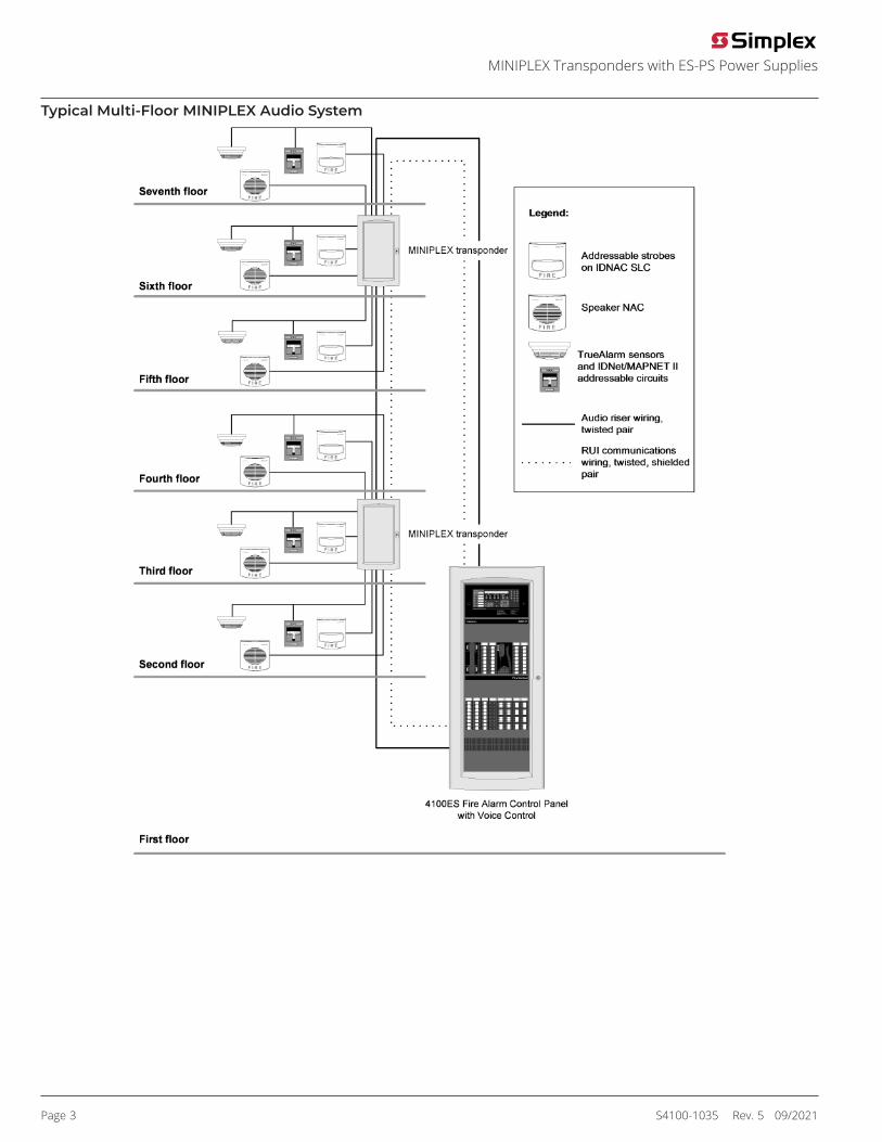
Introduction4100ES MINIPLEX transponders connect to a host 4100ES FireAlarm Control Panel using Simplex remote unit interface (RUI)communications. At the transponder, RUI communications are receivedby the transponder interface module and translated into the sameinternal communications format that is used in the host control panel.Remotely located modules. With RUI communications, thetransponder can remotely provide the same initiating and notificationfunctions that occur at the host control panel without requiring multiplelong distance wiring runs. Connections to the host panel are low currentcommunications and audio wiring with distances up to 2500 ft (762 m).Please refer to document S4100-1031 and the other documents listedin Additional 4100ES Product Reference for additional informationconcerning the extensive initiating and notification features of the4100ES fire alarm control panels.
Figure 1: Typical 4100ES MINIPLEX System One-Line Drawing
Module Bay DescriptionTransponder model 4100-9600 includes a bay assembly, a powerdistribution interface module (PDI), a Basic Transponder InterfaceModule, and an interconnect harness. Communications with the hostfire alarm control panel are via a Remote Unit Interface (RUI) connectionthat allows for up to 2500 ft (762 m) distance. RUI can communicate withup to a total of 31 remote devices and can be either Class B or Class Xcommunications.Transponder model 4100-9601 substitutes a Local Mode TransponderModule for the Basic Transponder Module.Optional Expansion Bays each include a PDI and accept a variety ofoptional modules (refer to tables from MINIPLEX Transponder ProductSelection onwards).The Battery Compartment (bottom) accepts two batteries, up to 50Ah, that can be mounted within the cabinet. Battery mounting doesnot interfere with available module space. A power supply with batterycharger is required for each battery set.
UL, ULC, CSFM Listed; FM Approved,OTCR/NYC Approved*
4100ES Fire Control Units
S4100-1035 Rev. 5 09/2021

Packaging Availability• Modules are power-limited (except as noted, such as battery chargers, city circuits and relay modules)• Enclosure are available for one, two, or three bay sizes or for cabinet rack mounting• NEMA 1/IP30 boxes and solid doors are available in platinum or red (ordered separately)• Up to eight close-nippled cabinets can be connected at one transponder location (close-nippled is mounted within 20 ft (6 m) and with
interconnecting wiring enclosed in conduit)• Refer to document S4100-0037 for enclosure details.
Local Mode Control OperationDefault Stand-Alone Operation. In the event of a communications loss with the host fire alarm control panel, model 4100-9601 MINIPLEX LocalMode Transponders provide fire alarm response default operation for its connected devices and appliances per the following:Input Operation. During local mode operation, conventional initiating devices and addressable IDNet initiating devices shall be capable of reportingan alarm condition to the MINIPLEX transponder. TrueAlarm sensors will cause an alarm at their least sensitive alarm threshold:• Photoelectric sensors will alarm at 3.7%/ft smoke obscuration• Heat sensors will alarm at a fixed temperature of 135 °F (57 °C)• TrueAlarm device LEDs will be activated to indicate a device in alarmNotification Operation. Fire alarm conditions reported against a fire alarm point type within a transponder in local mode will cause all notificationappliance circuits in that transponder to:• Sound a general alarm temporal pattern horn tone• Activate visible notification appliance circuitsLocal Mode Module Support. Local mode operation provides support for the following MINIPLEX transponder circuits:• Conventional NAC and addressable IDNAC notification appliance circuits, operated at a temporal pattern,• IDNet, IDNet 2 and IDNet 2+2 addressable device circuits• 4100ES amplifiers will provide their on-board horn tones (500 Hz) at a temporal pattern through their on-board amplifier NACs• Firefighter Telephone control modules in local modeLocal Mode Operation Module Exclusion. Modules and circuits not listed above but that are listed as compatible with MINIPLEX transponders perthis document, do not interfere with local mode operation but are not supported during local mode operation.
Local Mode ControllerOperation. During local mode operation, an optional Local Mode Controller will indicate status (see Figure 2) and can be enabled using akeyswitch to perform local alarm silence or reset. If alarms occurring during local mode are reset using a Local Mode Controller, upon restoration ofcommunications, those alarms will not be sent to the master controller. If alarms are still present upon restoration of communications, then thealarm condition will be reported and host fire alarm control panel programmed alarm functions will occur. When communications are re-established,the local mode transponder restores automatically.Mounting. Local Mode Controllers are mounted on three-gang plates, are available in beige or red, and for either flush or semi-flush mounting. (SeeLocal Mode Controller and 579-343 operating instructions for details).
Figure 2: Local Mode Controller Module
Page 2 S4100-1035 Rev. 5 09/2021
MINIPLEX Transponders with ES-PS Power Supplies
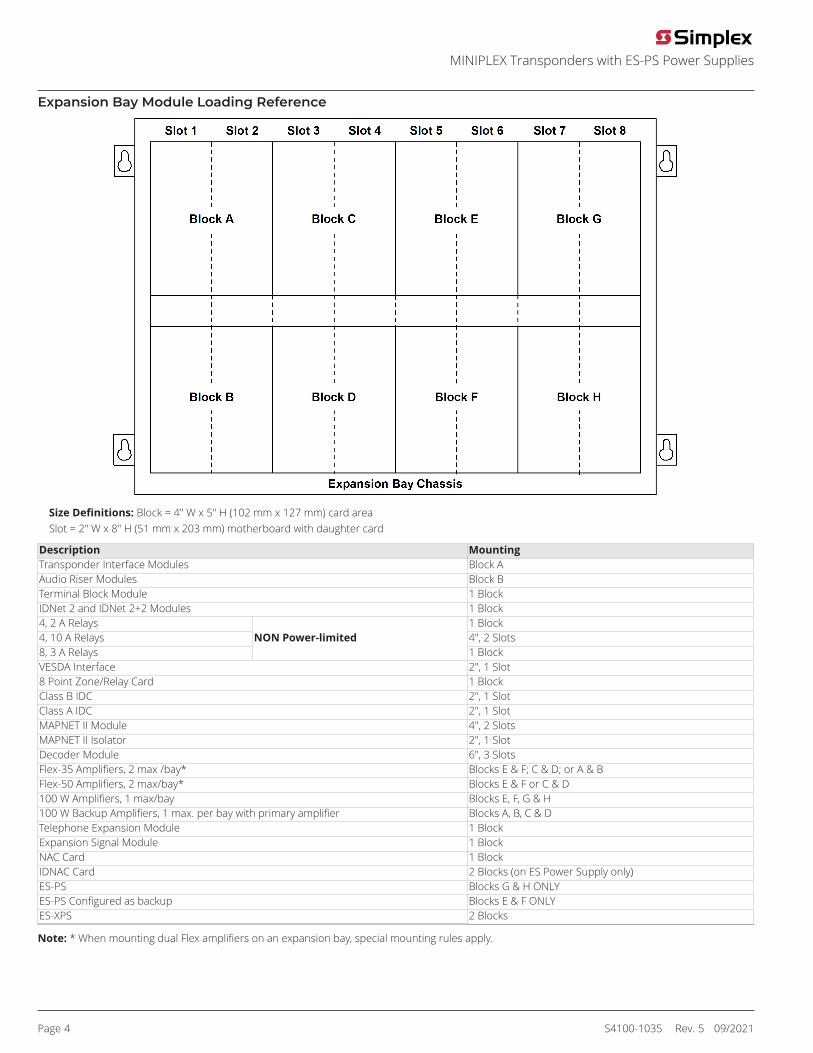
Typical Multi-Floor MINIPLEX Audio System
Page 3 S4100-1035 Rev. 5 09/2021
MINIPLEX Transponders with ES-PS Power Supplies
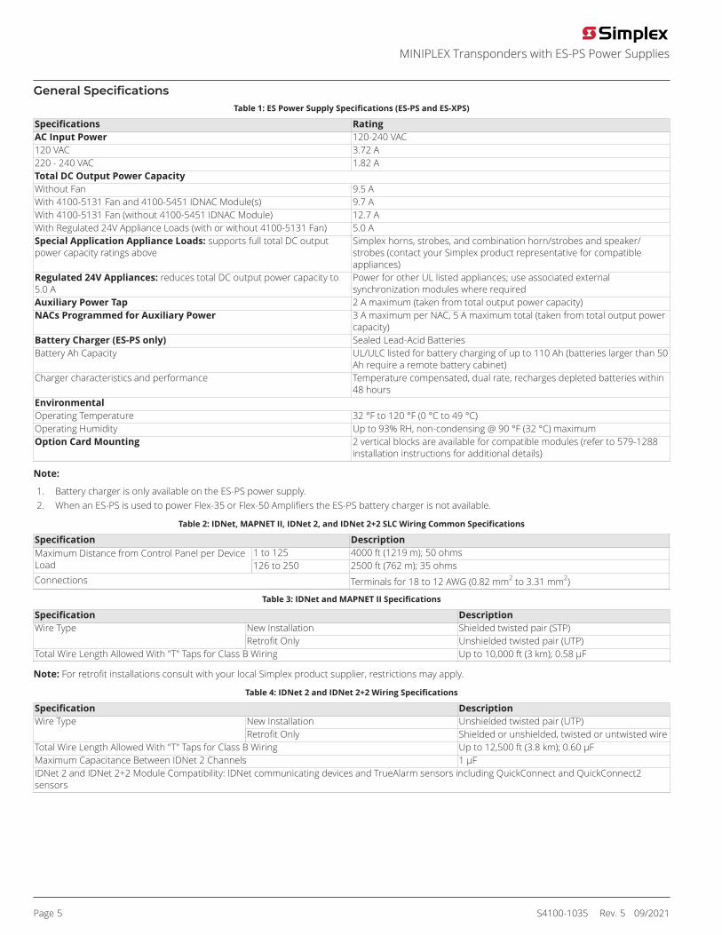
Expansion Bay Module Loading Reference
Size Definitions: Block = 4" W x 5" H (102 mm x 127 mm) card areaSlot = 2" W x 8" H (51 mm x 203 mm) motherboard with daughter card
Description MountingTransponder Interface Modules Block AAudio Riser Modules Block BTerminal Block Module 1 BlockIDNet 2 and IDNet 2+2 Modules 1 Block4, 2 A Relays 1 Block4, 10 A Relays 4", 2 Slots8, 3 A Relays
NON Power-limited1 Block
VESDA Interface 2", 1 Slot8 Point Zone/Relay Card 1 BlockClass B IDC 2", 1 SlotClass A IDC 2", 1 SlotMAPNET II Module 4", 2 SlotsMAPNET II Isolator 2", 1 SlotDecoder Module 6", 3 SlotsFlex-35 Amplifiers, 2 max /bay* Blocks E & F; C & D; or A & BFlex-50 Amplifiers, 2 max/bay* Blocks E & F or C & D100 W Amplifiers, 1 max/bay Blocks E, F, G & H100 W Backup Amplifiers, 1 max. per bay with primary amplifier Blocks A, B, C & DTelephone Expansion Module 1 BlockExpansion Signal Module 1 BlockNAC Card 1 BlockIDNAC Card 2 Blocks (on ES Power Supply only)ES-PS Blocks G & H ONLYES-PS Configured as backup Blocks E & F ONLYES-XPS 2 Blocks
Note: * When mounting dual Flex amplifiers on an expansion bay, special mounting rules apply.
Page 4 S4100-1035 Rev. 5 09/2021
MINIPLEX Transponders with ES-PS Power Supplies
General SpecificationsTable 1: ES Power Supply Specifications (ES-PS and ES-XPS)
Specifications RatingAC Input Power 120-240 VAC120 VAC 3.72 A220 - 240 VAC 1.82 ATotal DC Output Power CapacityWithout Fan 9.5 AWith 4100-5131 Fan and 4100-5451 IDNAC Module(s) 9.7 AWith 4100-5131 Fan (without 4100-5451 IDNAC Module) 12.7 AWith Regulated 24V Appliance Loads (with or without 4100-5131 Fan) 5.0 ASpecial Application Appliance Loads: supports full total DC outputpower capacity ratings above
Simplex horns, strobes, and combination horn/strobes and speaker/strobes (contact your Simplex product representative for compatibleappliances)
Regulated 24V Appliances: reduces total DC output power capacity to5.0 A
Power for other UL listed appliances; use associated externalsynchronization modules where required
Auxiliary Power Tap 2 A maximum (taken from total output power capacity)NACs Programmed for Auxiliary Power 3 A maximum per NAC, 5 A maximum total (taken from total output power
capacity)Battery Charger (ES-PS only) Sealed Lead-Acid BatteriesBattery Ah Capacity UL/ULC listed for battery charging of up to 110 Ah (batteries larger than 50
Ah require a remote battery cabinet)Charger characteristics and performance Temperature compensated, dual rate, recharges depleted batteries within
48 hoursEnvironmentalOperating Temperature 32 °F to 120 °F (0 °C to 49 °C)Operating Humidity Up to 93% RH, non-condensing @ 90 °F (32 °C) maximumOption Card Mounting 2 vertical blocks are available for compatible modules (refer to 579-1288
installation instructions for additional details)
Note:
1. Battery charger is only available on the ES-PS power supply.2. When an ES-PS is used to power Flex-35 or Flex-50 Amplifiers the ES-PS battery charger is not available.
Table 2: IDNet, MAPNET II, IDNet 2, and IDNet 2+2 SLC Wiring Common Specifications
Specification Description1 to 125 4000 ft (1219 m); 50 ohmsMaximum Distance from Control Panel per Device
Load 126 to 250 2500 ft (762 m); 35 ohmsConnections Terminals for 18 to 12 AWG (0.82 mm2 to 3.31 mm2)
Table 3: IDNet and MAPNET II Specifications
Specification DescriptionNew Installation Shielded twisted pair (STP)Wire TypeRetrofit Only Unshielded twisted pair (UTP)
Total Wire Length Allowed With "T" Taps for Class B Wiring Up to 10,000 ft (3 km); 0.58 μF
Note: For retrofit installations consult with your local Simplex product supplier, restrictions may apply.
Table 4: IDNet 2 and IDNet 2+2 Wiring Specifications
Specification DescriptionNew Installation Unshielded twisted pair (UTP)Wire TypeRetrofit Only Shielded or unshielded, twisted or untwisted wire
Total Wire Length Allowed With "T" Taps for Class B Wiring Up to 12,500 ft (3.8 km); 0.60 μFMaximum Capacitance Between IDNet 2 Channels 1 μFIDNet 2 and IDNet 2+2 Module Compatibility: IDNet communicating devices and TrueAlarm sensors including QuickConnect and QuickConnect2sensors
Page 5 S4100-1035 Rev. 5 09/2021
MINIPLEX Transponders with ES-PS Power Supplies
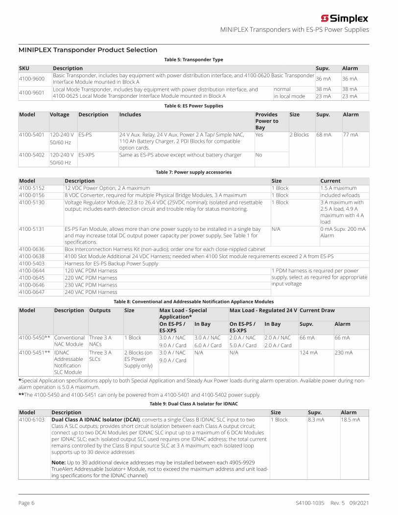
MINIPLEX Transponder Product SelectionTable 5: Transponder Type
SKU Description Supv. Alarm
4100-9600 Basic Transponder, includes bay equipment with power distribution interface, and 4100-0620 Basic TransponderInterface Module mounted in Block A 36 mA 36 mA
normal 38 mA 38 mA4100-9601 Local Mode Transponder, includes bay equipment with power distribution interface, and
4100-0625 Local Mode Transponder Interface Module mounted in Block A in local mode 23 mA 23 mA
Table 6: ES Power Supplies
Model Voltage Description Includes ProvidesPower toBay
Size Supv. Alarm
4100-5401 120-240 V50/60 Hz
ES-PS 24 V Aux. Relay, 24 V Aux. Power 2 A Tap/ Simple NAC,110 Ah Battery Charger, 2 PDI Blocks for compatibleoption cards.
Yes
4100-5402 120-240 V50/60 Hz
ES-XPS Same as ES-PS above except without battery charger No
2 Blocks 68 mA 77 mA
Table 7: Power supply accessories
Model Description Size Current4100-5152 12 VDC Power Option, 2 A maximum 1 Block 1.5 A maximum4100-0156 8 VDC Converter, required for multiple Physical Bridge Modules, 3 A maximum 1 Block included w/loads4100-5130 Voltage Regulator Module, 22.8 to 26.4 VDC (25VDC nominal); isolated and resettable
output; includes earth detection circuit and trouble relay for status monitoring.1 Block 3 A maximum with
2.5 A load, 4.9 Amaximum with 4 Aload
4100-5131 ES-PS Fan Module, allows more than one power supply to be installed in a single bayand may increase total DC output power capacity per power supply. See Table 1 forspecifications.
N/A 0 mA Supv. 200 mAAlarm
4100-0636 Box Interconnection Harness Kit (non-audio); order one for each close-nippled cabinet4100-0638 4100 Slot Module Additional 24 VDC Harness; needed when 4100 Slot module requirements exceed 2 A from ES-PS4100-5403 Harness for ES-PS Backup Power Supply4100-0644 120 VAC PDM Harness4100-0645 220 VAC PDM Harness4100-0646 230 VAC PDM Harness4100-0647 240 VAC PDM Harness
1 PDM harness is required per powersupply, select as required for appropriateinput voltage
Table 8: Conventional and Addressable Notification Appliance Modules
Max Load - SpecialApplication*
Max Load - Regulated 24 V Current DrawModel Description Outputs Size
On ES-PS /ES-XPS
In Bay On ES-PS /ES-XPS
In Bay Supv. Alarm
4100-5450** ConventionalNAC Module
Three 3 ANACs
1 Block 3.0 A / NAC9.0 A / Card
3.0 A / NAC6.0 A / Card
2.0 A / NAC5.0 A / Card
2.0 A / NAC2.0 A / Card
66 mA 66 mA
4100-5451** IDNACAddressableNotificationSLC Module
Three 3 ASLCs
2 Blocks (onES PowerSupply only)
3.0 A / NAC9.0 A / Card
N/A N/A 124 mA 230 mA
*Special Application specifications apply to both Special Application and Steady Aux Power loads during alarm operation. Available power during non-alarm operation is 5.0 A maximum.**The 4100-5450 and 4100-5451 can only be powered from a 4100-5401 and 4100-5402 power supply.
Table 9: Dual Class A Isolator for IDNAC
Model Description Size Supv. Alarm4100-6103 Dual Class A IDNAC Isolator (DCAI), converts a single Class B IDNAC SLC input to two
Class A SLC outputs; provides short circuit isolation between each Class A output circuit;connect up to two DCAI Modules per IDNAC SLC input up to a maximum of 6 DCAI Modulesper IDNAC SLC; each isolated output SLC used requires one IDNAC address; the total currentremains controlled by the Class B input source SLC at 3 A maximum; each isolated loopsupports up to 30 device addresses
Note: Up to 30 additional device addresses may be installed between each 4905-9929TrueAlert Addressable Isolator+ Module, not to exceed the maximum address and unit load-ing specifications for the IDNAC channel)
1 Block 8.3 mA 18.5 mA
Page 6 S4100-1035 Rev. 5 09/2021
MINIPLEX Transponders with ES-PS Power Supplies

Table 10: Addressable Interface Modules
Model Description Devices Supv. Alarmno devices 50 mA 60 mA50 devices 90 mA 150 mA125 devices 150 mA 225 mA
4100-3109* IDNet 2 Module, 250 point capacity; electrically isolated output with two short circuitisolating Class B or Class A output loops, 1 block; standard on EPS with IDNet 2 Module
250 devices 250 mA 350 mAno devices 50 mA 60 mA50 devices 90 mA 150 mA125 devices 150 mA 225 mA
4100-3110* IDNet 2+2 Module, 250 point capacity; electrically isolated output with four short circuitisolating Class B or Class A output loops, 1 block; mounts in expansion bay or availablemaster controller bay module locations only, not applicable for EPS mounting
250 devices 250 mA 350 mA4100-3111* IDNet Short Circuit Isolating Loop Output Module; for Aftermarket Field Installation Only; mount up to two on a 4100-3109
module; for use with 4100-3109 modules only4100-3102 MAPNET II Module, 127 point capacity, add devices separately; Module size = 2 Slots;
Loading per MAPNET II device = 1.7 mAModule withoutdevices
255 mA 275 mA
4100-3103 Isolator Module for MAPNET II communications; converts a single connected SLC into four isolated outputsselectable as Class A or Class B; up to two Isolator Modules can be connected to one SLC; Module size = 1Slot;
Note: Compatible with MAPNET II Remote Isolators only
50 mA 50 mA
*Note: See Table for current draw for each IDNet device
Table 11: Current draw for each IDNet device
Condition CurrentStandby 0.8 mAAlarm, with LED off 1.0 mAAlarm, with LED on 3.0 mANote: A maximum of 20 devices with LED on is supported for each channel. Additional device LEDs do not turn on.
Table 12: 8-Point Zone/Relay Card
Model Description Size Supv. Alarm4100-5013 8 point zone/relay 4x5” flat module. Mounts in any open block in a master
controller or expansion bay. Alarm current shown is for 8 Class B IDCs using 3.3Kend-of-line-resistors with 4 in alarm and 4 in standby. Standby current shownis for all 8 IDCs in standby. Refer to 579-1236 Zone/Relay Module InstallationInstructions for additional information.
1 block 83 mA 351 mA
4100-6305 25V regulator harness for 8 point zone/relay module. One required for each 8point zone/relay module to be powered by the 4100-5130 25V regulator module. Amaximum of (5) 8 point zone/relay modules may be powered from the 4100-5130per bay.
N/A N/A N/A
Note: Modules in Table 12 requires 4100ES Version 3.06 or later.
Table 13: Relay Modules; Non-power-limited
Model Description Resistive Ratings Inductive Ratings Size Supv. Alarm4100-3202 4 DPDT w/
feedback10 A 250 VAC 10 A 250 VAC 2 Slots 15 mA 175 mA
4100-3204 4 DPDT w/feedback
2 A 30 VDC/VAC ½ A 30 VDC/120VAC
1 Block 15 mA 60 mA
4100-3206 8 SPDT 3 A 30 VDC/120VAC
1 ½ A 30 VDC/120VAC
1 Block 15 mA 190 mA
Current Calculation Notes:1. For total supervisory current, add panel module currents to base system and add all external loads panel-powered loads.2. For total alarm current, add panel module currents to base system alarm current and add all panel NAC loads and all external loads powered frompanel power supplies.
Table 14: Communication Modules
SKU Description Size Supv. Alarm4100-1291 Remote Unit Interface Module (RUI, unisolated), up to 3 maximum per control panel; for use with
4100-9600 only1 Slot 85 mA 85 mA
4100-6031 City Circuit, with disconnect switches 20 mA 36 mA4100-6032 City Circuit, without disconnect switches 20 mA 36 mA4100-6033
Select one per ESPower Supply (nonpower-limited) Alarm Relay, 3 Form C relays, 2 A @ 32
VDC; for ES-PS
For use with ES-PS only (not forbackup ES-PS or ES-XPS)
1 Block
15 mA 37 mA
4100-6038 Dual RS-232 Interface 1 Slot 132 mA 132 mA4100-6045 Decoder Module 3 Slots 85 mA 163 mA
Page 7 S4100-1035 Rev. 5 09/2021
MINIPLEX Transponders with ES-PS Power Supplies
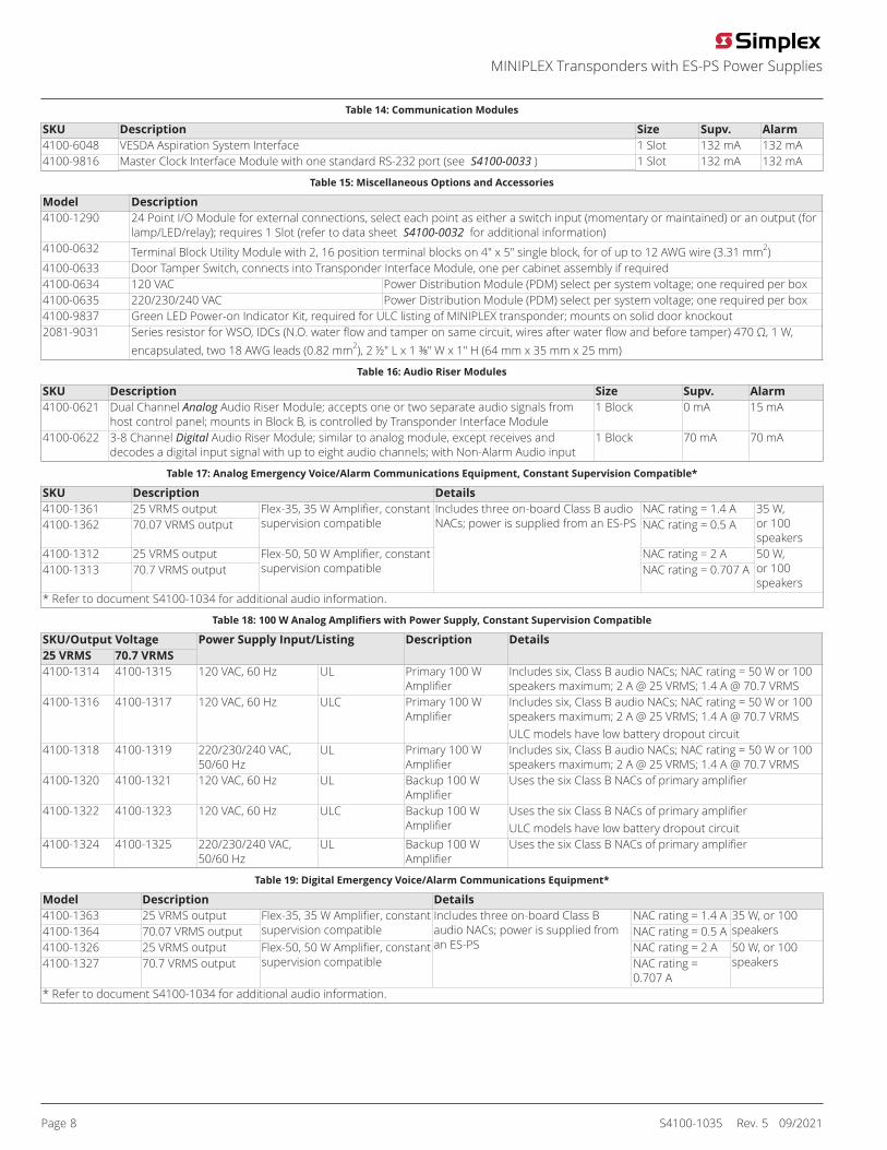
Table 14: Communication Modules
SKU Description Size Supv. Alarm4100-6048 VESDA Aspiration System Interface 1 Slot 132 mA 132 mA4100-9816 Master Clock Interface Module with one standard RS-232 port (see S4100-0033 ) 1 Slot 132 mA 132 mA
Table 15: Miscellaneous Options and Accessories
Model Description4100-1290 24 Point I/O Module for external connections, select each point as either a switch input (momentary or maintained) or an output (for
lamp/LED/relay); requires 1 Slot (refer to data sheet S4100-0032 for additional information)4100-0632 Terminal Block Utility Module with 2, 16 position terminal blocks on 4" x 5" single block, for of up to 12 AWG wire (3.31 mm2)4100-0633 Door Tamper Switch, connects into Transponder Interface Module, one per cabinet assembly if required4100-0634 120 VAC Power Distribution Module (PDM) select per system voltage; one required per box4100-0635 220/230/240 VAC Power Distribution Module (PDM) select per system voltage; one required per box4100-9837 Green LED Power-on Indicator Kit, required for ULC listing of MINIPLEX transponder; mounts on solid door knockout2081-9031 Series resistor for WSO, IDCs (N.O. water flow and tamper on same circuit, wires after water flow and before tamper) 470 Ω, 1 W,
encapsulated, two 18 AWG leads (0.82 mm2), 2 ½" L x 1 ⅜" W x 1" H (64 mm x 35 mm x 25 mm)
Table 16: Audio Riser Modules
SKU Description Size Supv. Alarm4100-0621 Dual Channel Analog Audio Riser Module; accepts one or two separate audio signals from
host control panel; mounts in Block B, is controlled by Transponder Interface Module1 Block 0 mA 15 mA
4100-0622 3-8 Channel Digital Audio Riser Module; similar to analog module, except receives anddecodes a digital input signal with up to eight audio channels; with Non-Alarm Audio input
1 Block 70 mA 70 mA
Table 17: Analog Emergency Voice/Alarm Communications Equipment, Constant Supervision Compatible*
SKU Description Details4100-1361 25 VRMS output NAC rating = 1.4 A4100-1362 70.07 VRMS output
Flex-35, 35 W Amplifier, constantsupervision compatible NAC rating = 0.5 A
35 W,or 100speakers
4100-1312 25 VRMS output NAC rating = 2 A4100-1313 70.7 VRMS output
Flex-50, 50 W Amplifier, constantsupervision compatible
Includes three on-board Class B audioNACs; power is supplied from an ES-PS
NAC rating = 0.707 A50 W,or 100speakers
* Refer to document S4100-1034 for additional audio information.
Table 18: 100 W Analog Amplifiers with Power Supply, Constant Supervision Compatible
SKU/Output Voltage25 VRMS 70.7 VRMS
Power Supply Input/Listing Description Details
4100-1314 4100-1315 120 VAC, 60 Hz UL Primary 100 WAmplifier
Includes six, Class B audio NACs; NAC rating = 50 W or 100speakers maximum; 2 A @ 25 VRMS; 1.4 A @ 70.7 VRMS
4100-1316 4100-1317 120 VAC, 60 Hz ULC Primary 100 WAmplifier
Includes six, Class B audio NACs; NAC rating = 50 W or 100speakers maximum; 2 A @ 25 VRMS; 1.4 A @ 70.7 VRMSULC models have low battery dropout circuit
4100-1318 4100-1319 220/230/240 VAC,50/60 Hz
UL Primary 100 WAmplifier
Includes six, Class B audio NACs; NAC rating = 50 W or 100speakers maximum; 2 A @ 25 VRMS; 1.4 A @ 70.7 VRMS
4100-1320 4100-1321 120 VAC, 60 Hz UL Backup 100 WAmplifier
Uses the six Class B NACs of primary amplifier
4100-1322 4100-1323 120 VAC, 60 Hz ULC Backup 100 WAmplifier
Uses the six Class B NACs of primary amplifierULC models have low battery dropout circuit
4100-1324 4100-1325 220/230/240 VAC,50/60 Hz
UL Backup 100 WAmplifier
Uses the six Class B NACs of primary amplifier
Table 19: Digital Emergency Voice/Alarm Communications Equipment*
Model Description Details4100-1363 25 VRMS output NAC rating = 1.4 A4100-1364 70.07 VRMS output
Flex-35, 35 W Amplifier, constantsupervision compatible NAC rating = 0.5 A
35 W, or 100speakers
4100-1326 25 VRMS output NAC rating = 2 A4100-1327 70.7 VRMS output
Flex-50, 50 W Amplifier, constantsupervision compatible
Includes three on-board Class Baudio NACs; power is supplied froman ES-PS
NAC rating =0.707 A
50 W, or 100speakers
* Refer to document S4100-1034 for additional audio information.
Page 8 S4100-1035 Rev. 5 09/2021
MINIPLEX Transponders with ES-PS Power Supplies
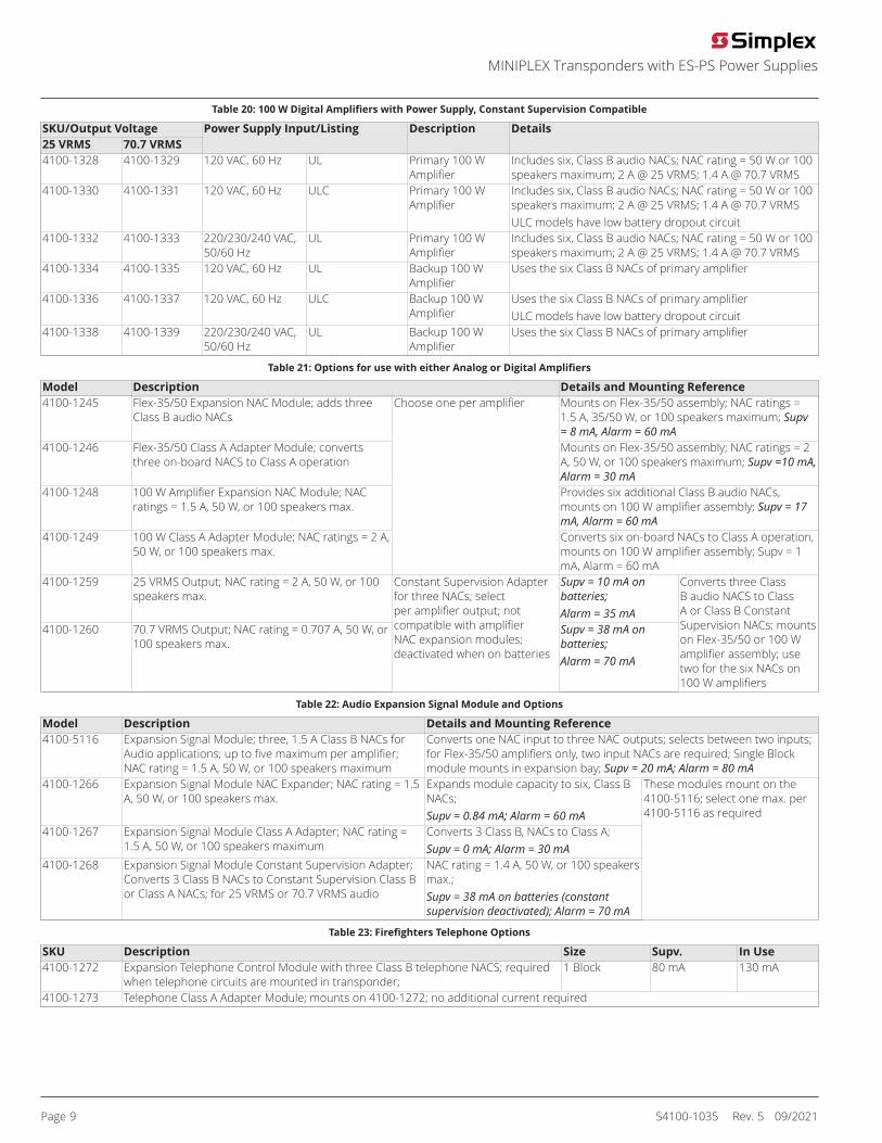
Table 20: 100 W Digital Amplifiers with Power Supply, Constant Supervision Compatible
SKU/Output Voltage25 VRMS 70.7 VRMS
Power Supply Input/Listing Description Details
4100-1328 4100-1329 120 VAC, 60 Hz UL Primary 100 WAmplifier
Includes six, Class B audio NACs; NAC rating = 50 W or 100speakers maximum; 2 A @ 25 VRMS; 1.4 A @ 70.7 VRMS
4100-1330 4100-1331 120 VAC, 60 Hz ULC Primary 100 WAmplifier
Includes six, Class B audio NACs; NAC rating = 50 W or 100speakers maximum; 2 A @ 25 VRMS; 1.4 A @ 70.7 VRMSULC models have low battery dropout circuit
4100-1332 4100-1333 220/230/240 VAC,50/60 Hz
UL Primary 100 WAmplifier
Includes six, Class B audio NACs; NAC rating = 50 W or 100speakers maximum; 2 A @ 25 VRMS; 1.4 A @ 70.7 VRMS
4100-1334 4100-1335 120 VAC, 60 Hz UL Backup 100 WAmplifier
Uses the six Class B NACs of primary amplifier
4100-1336 4100-1337 120 VAC, 60 Hz ULC Backup 100 WAmplifier
Uses the six Class B NACs of primary amplifierULC models have low battery dropout circuit
4100-1338 4100-1339 220/230/240 VAC,50/60 Hz
UL Backup 100 WAmplifier
Uses the six Class B NACs of primary amplifier
Table 21: Options for use with either Analog or Digital Amplifiers
Model Description Details and Mounting Reference4100-1245 Flex-35/50 Expansion NAC Module; adds three
Class B audio NACsMounts on Flex-35/50 assembly; NAC ratings =1.5 A, 35/50 W, or 100 speakers maximum; Supv= 8 mA, Alarm = 60 mA
4100-1246 Flex-35/50 Class A Adapter Module; convertsthree on-board NACS to Class A operation
Mounts on Flex-35/50 assembly; NAC ratings = 2A, 50 W, or 100 speakers maximum; Supv =10 mA,Alarm = 30 mA
4100-1248 100 W Amplifier Expansion NAC Module; NACratings = 1.5 A, 50 W, or 100 speakers max.
Provides six additional Class B audio NACs,mounts on 100 W amplifier assembly; Supv = 17mA, Alarm = 60 mA
4100-1249 100 W Class A Adapter Module; NAC ratings = 2 A,50 W, or 100 speakers max.
Choose one per amplifier
Converts six on-board NACs to Class A operation,mounts on 100 W amplifier assembly; Supv = 1mA, Alarm = 60 mA
4100-1259 25 VRMS Output; NAC rating = 2 A, 50 W, or 100speakers max.
Supv = 10 mA onbatteries;Alarm = 35 mA
4100-1260 70.7 VRMS Output; NAC rating = 0.707 A, 50 W, or100 speakers max.
Constant Supervision Adapterfor three NACs; selectper amplifier output; notcompatible with amplifierNAC expansion modules;deactivated when on batteries
Supv = 38 mA onbatteries;Alarm = 70 mA
Converts three ClassB audio NACS to ClassA or Class B ConstantSupervision NACs; mountson Flex-35/50 or 100 Wamplifier assembly; usetwo for the six NACs on100 W amplifiers
Table 22: Audio Expansion Signal Module and Options
Model Description Details and Mounting Reference4100-5116 Expansion Signal Module; three, 1.5 A Class B NACs for
Audio applications; up to five maximum per amplifier;NAC rating = 1.5 A, 50 W, or 100 speakers maximum
Converts one NAC input to three NAC outputs; selects between two inputs;for Flex-35/50 amplifiers only, two input NACs are required; Single Blockmodule mounts in expansion bay; Supv = 20 mA; Alarm = 80 mA
4100-1266 Expansion Signal Module NAC Expander; NAC rating = 1.5A, 50 W, or 100 speakers max.
Expands module capacity to six, Class BNACs;Supv = 0.84 mA; Alarm = 60 mA
4100-1267 Expansion Signal Module Class A Adapter; NAC rating =1.5 A, 50 W, or 100 speakers maximum
Converts 3 Class B, NACs to Class A;Supv = 0 mA; Alarm = 30 mA
4100-1268 Expansion Signal Module Constant Supervision Adapter;Converts 3 Class B NACs to Constant Supervision Class Bor Class A NACs; for 25 VRMS or 70.7 VRMS audio
NAC rating = 1.4 A, 50 W, or 100 speakersmax.;Supv = 38 mA on batteries (constantsupervision deactivated); Alarm = 70 mA
These modules mount on the4100-5116; select one max. per4100-5116 as required
Table 23: Firefighters Telephone Options
SKU Description Size Supv. In Use4100-1272 Expansion Telephone Control Module with three Class B telephone NACS; required
when telephone circuits are mounted in transponder;1 Block 80 mA 130 mA
4100-1273 Telephone Class A Adapter Module; mounts on 4100-1272; no additional current required
Page 9 S4100-1035 Rev. 5 09/2021
MINIPLEX Transponders with ES-PS Power Supplies
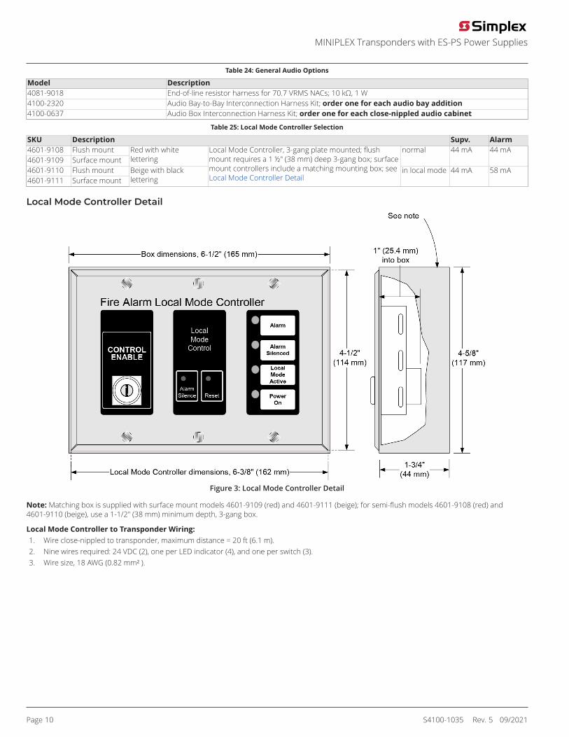
Table 24: General Audio Options
Model Description4081-9018 End-of-line resistor harness for 70.7 VRMS NACs; 10 kΩ, 1 W4100-2320 Audio Bay-to-Bay Interconnection Harness Kit; order one for each audio bay addition4100-0637 Audio Box Interconnection Harness Kit; order one for each close-nippled audio cabinet
Table 25: Local Mode Controller Selection
SKU Description Supv. Alarm4601-9108 Flush mount4601-9109 Surface mount
Red with whitelettering
normal 44 mA 44 mA
4601-9110 Flush mount4601-9111 Surface mount
Beige with blacklettering
Local Mode Controller, 3-gang plate mounted; flushmount requires a 1 ½" (38 mm) deep 3-gang box; surfacemount controllers include a matching mounting box; seeLocal Mode Controller Detail
in local mode 44 mA 58 mA
Local Mode Controller Detail
Figure 3: Local Mode Controller Detail
Note: Matching box is supplied with surface mount models 4601-9109 (red) and 4601-9111 (beige); for semi-flush models 4601-9108 (red) and4601-9110 (beige), use a 1-1/2" (38 mm) minimum depth, 3-gang box.
Local Mode Controller to Transponder Wiring:1. Wire close-nippled to transponder, maximum distance = 20 ft (6.1 m).2. Nine wires required: 24 VDC (2), one per LED indicator (4), and one per switch (3).3. Wire size, 18 AWG (0.82 mm² ).
Page 10 S4100-1035 Rev. 5 09/2021
MINIPLEX Transponders with ES-PS Power Supplies
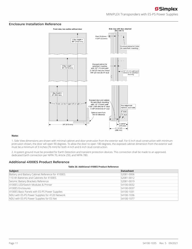
Enclosure Installation Reference
Note:
1. Side View dimensions are shown with minimal cabinet and door protrusion from the exterior wall. For 6 inch stud construction with minimumprotrusion shown, the door will open 90 degrees. To allow the door to open 180 degrees, the exposed cabinet dimension from the exterior wallmust be a minimum of 3 inches (76 mm) for both 4 inch and 6 inch stud construction.
2. A system ground must be provided for Earth Detection and transient protection devices. This connection shall be made to an approved,dedicated Earth connection per NFPA 70, Article 250, and NFPA 780.
Additional 4100ES Product ReferenceTable 26: Additional 4100ES Product Reference
Subject DatasheetBattery and Battery Cabinet Reference for 4100ES S2081-0006110 Ah Batteries and Cabinets for 4100ES S2081-0012Seismic Battery Brackets Reference S2081-00194100ES LED/Switch Modules & Printer S4100-00324100ES Enclosures S4100-00374100ES Basic Panels with ES-PS Power Supplies S4100-1031NDU with ES-PS Power Supplies for 4120 Network S4100-1036NDU with ES-PS Power Supplies for ES Net S4100-1077
Page 11 S4100-1035 Rev. 5 09/2021
MINIPLEX Transponders with ES-PS Power Supplies

S4100-1035 Rev. 5 09/2021
© 2021 Johnson Controls. All rights reserved. All specifications and other information shown were current as of document revision and are subject to change withoutnotice. Additional listings may be applicable, contact your local Simplex® product supplier for the latest status. Listings and approvals under Simplex Time Recorder Co.Simplex, and the product names listed in this material are marks and/or registered marks. Unauthorized use is strictly prohibited. NFPA 72 and National Fire Alarm Code areregistered trademarks of the National Fire Protection Association (NFPA).
MINIPLEX Transponders with ES-PS Power Supplies