miraflores feasibility study
TRANSCRIPT

ASX ANNOUNCEMENT METMINCO LIMITED
30 October 2017
ASX ANNOUNCEMENT 30 October 2017
Miraflores Feasibility Study
Metminco Limited (ASX: MNC, AIM: MNC) (“Metminco” or the “Company”) is pleased to announce the details of the feasibility study technical findings for the development of its Miraflores Gold Project in Quinchia, Department of Risaralda, Colombia (the “Project”). HIGHLIGHTS
Maiden Ore Reserve Estimate; Metminco has declared a maiden NI 43-101 and JORC 2012-compliant Ore Reserve for Miraflores of 4.326Mt @ 3.29g/t Au for 456,000 contained ounces of gold.
Ore Reserve Estimate – Miraflores Gold Project (October 2017, 100% basis)
Reserve Classification Tonnes (t) Gold (g/t)
Silver (g/t)Contained Metal (Koz
Au)
Contained Metal (Koz
Ag)
Proved 835,606 4.84 2.73 130 73
Probable 2,142,741 4.16 3.21 287 221
Proved + Probable 2,978,346 4.35 3.08 417 295
Planned dilution 1,347,867 0.91 1.42 39 62
Total Ore Reserve 4,326,213 3.29 2.57 456 357
Source: Ausenco, 2017
The Company announced in September 2017 that it had received approval from the Corporacion Autonoma Del Risaralda (CARDER), the environmental agency in the Department of Risaralda, Colombia, to construct up to 2,000 metres of underground development under the Company’s existing Plan De Manejo Ambiental (PMA). The Company is assessing options for funding the underground development.
With the granting of this permit the Company now has the option to commence underground development of the mine which Metminco believes would provide valuable technical details of the orebody ahead of a decision to proceed with construction of the plant and infrastructure. The permit provides for placement of waste on surface and allows for surface discharge of water from the mine.
The processing plant has been designed to operate at a treatment rate of 1,300tpd. Detailed metallurgical testwork has demonstrated recoveries of 92% and 60% for gold and silver respectively.
The After Tax NPV (8% DR), IRR and Payback for the base case are US$72.3 million, 25% and 3.6 years respectively (NPV at 5% DR is US$96.1 million)
It is envisaged that the project will be constructed over an 18 month period from the commencement of detailed engineering (1 March 2018 commencement date). The early definition of major equipment such as mills, crushers, thickening and filtering equipment is critical for maintaining the project timeline and will be undertaken in a 3 to 4 month front end engineering design (FEED) phase prior to project full commencement. Commencement of site works is subject to EIA approval.
Mr William Howe, Managing Director, said: “The outcome of the feasibility study is testament to the professionalism and dedication of the feasibility study team. The extensive experience of the individuals is demonstrated by the innovative thinking that has culminated in a low cost, fit for purpose mining and processing project.”

ASX ANNOUNCEMENT METMINCO LIMITED
30 October 2017
MIRAFLORES FEASIBILITY STUDY
Introduction
The Miraflores Feasibility Study (“Report” or “Study”) has been prepared following the guidelines of the Canadian Securities Administrators’ National Instrument 43-101 and Form 43-101F1 and the JORC code (2012). The Mineral Resource Statement reported herein was prepared in conformity with generally accepted “Estimation of Mineral Resources and Mineral Reserves Best Practice Guidelines” (CIM Guidelines) in 2012 and updated in 2016 to comply with the NI 43-101 and the JORC Code (2012 edition) (The Australasian Code for Reporting of Exploration Results, Mineral Resources and Ore Reserves (the JORC Code)).
Miraflores retained the services and coordinated the work of various subcontractors for the preparation and compilation of the Report. The work is not considered independent, although most of the consultants involved can be considered as such, because a portion of the Report, including the Economic Analysis section, has been authored by Miraflores. Miraflores is, however, classified as a producing issuer in terms of the Standards of Disclosure for Mineral Projects and is therefore fully competent through its in-house Qualified Persons to present these sections of the Report.
Property Description and Location
The Miraflores property consists of a 124-hectare mineral exploitation contract granted by the Colombian Ministry of Mines to the Asociación de Mineros de Miraflores ("Miraflores Miners Association"). Utilising the WGS-84 datum, the mineral contract forms a polygon centred at about 5°17'40"N and 75°41'33"W, or alternatively, UTM Zone 18 Northern Hemisphere, 423,650 east, 585,900 north. Geographically, the mineral contract is located within the Municipality of Quinchía, Department of Risaralda, Republic of Colombia, some 190km WNW of the Colombian capital of Bogota and 55 km to the north of Pereira, the capital of the Department of Risaralda.
Geology and Mineralisation
The Miraflores property is located overlooking the Cauca River valley, along the eastern margin of Colombia's physiographic Western Cordillera. The topography of the region is mountainous, characterised by high-relief, vegetated mountains and steeply incised active drainages.
The geological evolution of the region is complex, being linked to aggressive, collisionary Meso-Cenozoic tectonism associated with Northern Andean Block assembly along the Romeral fault and suture system. The accretion of various allochthonous terranes in western Colombia during the Miocene incited deformation, uplift, magmatism and erosion.
From a historic gold production standpoint, the Miraflores property is located within the Quinchía mining district and Miraflores itself has been a site of semi-continuous artisanal gold production dating from pre-Colombian times. From a metallogenetic standpoint, mineralisation in the Quinchía district is genetically linked to the emplacement of a cluster of Miocene-aged hypabyssal porphyry bodies. A variety of magmatic- hydrothermal Au (Cu) and Au-Ag (Pb, Zn, Cu) deposit types are associated with the geochemical and cooling history of the porphyry bodies.
MINERAL RESOURCES
As of 2 April 2013, Metal Mining Consultants (MMC) estimated a Measured and Indicated Mineral Resource of 72.6Mt at a gold and silver grade of 0.78 g/t and 1.52 g/t respectively using a cut-off grade of 0.27 g/t gold in accordance with NI 43-101. The Mineral Resource was based on 25,884 m of drilling in 73 diamond drill holes and 236m of underground channel samples. The Mineral Resource estimate provided for both an open pit and an underground mining operation.
More recently, MMC were retained by Metminco to produce a Mineral Resource that is estimated in accordance with the guidelines of the JORC Code (2012 Edition), but which only provided for the exploitation

ASX ANNOUNCEMENT METMINCO LIMITED
30 October 2017
of the Miraflores deposit via an underground mining operation, and hence a higher cut-off grade of 1.2g/t gold. The revised Mineral Resource estimate is summarised in the table below.
Mineral Resource Estimate – Miraflores Gold Project (MMC March 2017, 100% basis)
Classification Tonnes
(000's)
Au (g/t) Ag (g/t) Oz Au
(000's)
Oz Ag
(000's)
Measured
Indicated
2,958
6,311
2.98
2.74
2.49
2.90
283
557
237
588
Measured
&Indicated
9,269 2.82 2.77 840 825
Inferred 487 2.36 3.64 37 57
Total Mineral
Resources
9,756 2.80 2.81 877 882
Note: Based on a gold cut-off grade of 1.2g/t.
Rounding-off of numbers may result in minor computational errors, which are not deemed to be significant. Source: MMC, 2017
ORE RESERVES
The Project Ore Reserve Estimate, classified and reported in accordance with the Canadian Securities Administrators National Instrument 43-101 (NI 43-101) and the corresponding CIM Definition Standards on Mineral Resources and Ore Reserves and the JORC Code (2012), is listed in the table below.
Ore Reserve estimate as at October 2017 (100% basis)
Reserve Classification Tonnes (t) Gold (g/t)
Silver (g/t)Contained Metal (Koz
Au)
Contained Metal (Koz
Ag)
Proved 835,606 4.84 2.73 130 73
Probable 2,142,741 4.16 3.21 287 221
Proved + Probable 2,978,346 4.35 3.08 417 295
Planned dilution 1,347,867 0.91 1.42 39 62
Total Ore Reserve 4,326,213 3.29 2.57 456 357
Source: Ausenco, 2017
Note: Rounding-off of numbers may result in minor computational errors, which are not deemed
to be significant.
The Ore Reserve estimate is based on the following assumptions:
Ore Reserves are based on a gold price of US$1,200/oz;
Ore Reserves are defined within an underground mine plan generated from diluted
Mineral Resources;
An underground CoG of 1.53 g/t-Au was applied to underground resources constrained
by a final underground design;

ASX ANNOUNCEMENT METMINCO LIMITED
30 October 2017
Underground Ore Reserves assume 31% dilution;
In-situ Au ounces disregard metallurgical recovery of 92%;
28% of the mined-out stopes and drifts will use backfill including waste and filtered
tailings material. Backfilling operations will commence in the 2nd year of operation;
Detailed ventilation designs will be applied; and
Ore Reserves are based on topography received from Metminco on January 26, 2017.
MINING
Mining Method
Retreat longhole open stoping with backfill is the mining method proposed. This method permits the
extraction of the ore at maximum hydraulic radius after backfilling the stopes. The backfill assumed is waste
material from mining and fine tailings material. Backfill is required for both stability and environmental
reasons, allowing all waste material generated by the mining operation to be redeposited as fill in the mine.
Geotechnical
All the mine accesses will be developed in rock mass with good geotechnical conditions. The first 80m of the decline ramp will be developed in basalt before transitioning to breccia. The geotechnical characterisation is described in the geotechnical report (SRK, 2013).
Ground conditions can be described, according to the Q system, as “fair” in veins. Below surface (first 40 to 50m), where weathered and fractured rock mass is developed, the condition can be described as “good” for fresh basalt and “very good” for fresh breccia. The majority of ground conditions at Miraflores are classified as “good”.
The table below shows the geotechnical parameters for underground design and stability analysis.
GSI D C (Kpa) ɸ (°)Fresh 136 28,7 63 - 77 0,19 - 0,27 15 50 361 43Weathered 50 28,5 - - 12 27 - -Fresh 98 27,7 48 - 58 0,23 - 0,31 18 50 712 52Weathered - - - - 10 28 - -
miRock Mass Parameters
Basalt0,5
Breccia
Geotechnical Unit UCS (Mpa)Unit Weight
(KN/m3)E (Gpa) ν

ASX ANNOUNCEMENT METMINCO LIMITED
30 October 2017
Underground development
The following figure shows the underground development design.
Source: Ausenco, 2017 Using the geometrical parameters set out in the table below the stopes derived from the mining optimisation have been used as the basis for the mine design. These stopes define the ore extraction along the ore body. The optimisation considered a cut-off grade of 1.75 g/t Au for the average grade of the material contained within the stope, which permits the extraction at maximum grade and generates a plant feed that produces 4,000 oz per month. A 40m crown pillar to surface from the upper stopes has been allowed.
Geometrical parameters for optimisation Parameter Unit Amount Level interval m 26 Minimum mining width m 1.5 Hanging wall dilution width m 0.5
Footwall dilution width m 0.5
Total minimum mining width m 2.5
Section spacing m 6
Cut-off grade g/t Au 1.75 Source: Ausenco, 2017
The tables below show the vertical and horizontal development required for the Life of Mine (LoM).
Horizontal development
Development Width (m) Height (m) LoM Length (m) Profile
Ramp 4.5 4.5 5,157 Arched
Drift 4 4 15,435 Arched
Cross Cut 4 4 8,133 Arched
Passing bay 15 4 36 Arched
Muck Loading bay 4 4 530 Arched
Maintenance Station 10 4 30 Arched

ASX ANNOUNCEMENT METMINCO LIMITED
30 October 2017
Refuge Station 3.5 3.5 40 Arched
Dewatering bay 4 3 480 Arched
Electrical Substation bay
4 4 10 Arched
Drift Ventilation 4 4 1,088 Arched
Source: Ausenco, 2017
Vertical development
Development Method Width/diameter (m)
LoM Length (m)
Profile
Return airway Raiseborer 3.1 908 Round
Return airway VCR 5 370 Square
Source: Ausenco, 2017
Mining Schedule
The underground mining inventory including Inferred Resources is provided in the table below.
Miraflores production schedule
Description Units Total LoM
Total Tonnes (mineralisation + waste + low grade) (kt) 5,026
Mineralised Tonnes (Au > 1.53 g/t) (kt) 4,326
Mineralisation Au (g/t) 3.29
Mineralisation Ag (g/t) 2.56
Low Grade (0.6 g/t < Au < 1.53 g/t) (kt) 284
Low Grade Au (g/t) 0.88
Waste (Au < 0.6 g/t) (kt) 415
Drifts & Cross-cuts (4 m x 4 m) (m) 23,569
Ramp (4.5 m x 4.5 m) (m) 5,157
Source: Ausenco, 2017
Stope Design
Using the geometrical parameters set out in the table below, the stopes derived from the mining optimisation
have been used as the basis for the mine design. These stopes define the ore extraction along the ore body.
The optimisation considered a cut-off grade of 1.75 g/t Au for the average grade of the material contained
within the stope, which permits the extraction at maximum grade and generates a plant feed that produces
4,000 oz per month. A 40m crown pillar to surface from the upper stopes has been allowed.
Geometrical parameters for optimisation.
Parameter Unit Amount Level interval m 26 Minimum mining width m 1.5 Hanging wall dilution width m 0.5 Footwall dilution width m 0.5

ASX ANNOUNCEMENT METMINCO LIMITED
30 October 2017
Parameter Unit Amount Total minimum mining width m 2.5 Section spacing m 6 Cut-off grade g/t Au 1.75
Source: Ausenco, 2017
The figure below shows a sectional view of the stope design.
3D view of Stopes – Miraflores
Source: Ausenco, 2017
Ventilation
The mine has its own primary ventilation circuit. Taking into account the various characteristics of the
Miraflores Project design, such as the longhole open stopes and ore haulage by trucks on the main ramp,
the mine will be ventilated by an exhausting system using surface fans extracting through a VCR raise with a
section of 5 x 5 m. This raise, at 336 m in length, will connect the 1,071 mine level with the surface and
control air flow in the main extraction circuit.
The main ventilation system is an Exhaust System. Two main fans will be installed, operating in parallel.
These satisfy the operating criteria obtained by simulation carried out using the Ventsim Visual™ software.
Fresh air will enter the mine via five airways, namely three access portals and two bored raises with the air
flowing via ramps (main and secondary) to the production and development areas and the drifts that access
such levels.
Contaminated air will then be extracted from the various sectors of the mine to the Central VCR Raise (main
extraction shaft with surface elevation of 1,407 m.a.s.l.). This is driven by the pair of surface fans generating
the exhaust flow through the VCR raise.

ASX ANNOUNCEMENT METMINCO LIMITED
30 October 2017
Circuit of injection/extraction ventilation flows (blue - fresh air, red - extracted air)
Source: Ausenco, 2017
Underground Mine Equipment
Mining will be carried out as an owner-managed operation for the life of mine. The equipment required to
achieve the development, production and backfill schedule for the LoM is detailed below.
Mine equipment (LOM)
Equipment\Period Yr 1 Yr 2 Yr 3 Yr 4 Yr 5 Yr 6 Yr 7 Yr 8 Yr 9 Yr 10
Jumbo 3 3 3 2 2 1 - - - -
Longhole drill 2 2 2 2 2 2 2 2 2 2
LHD 3 3 3 3 2 2 2 2 2 1
Front End Loader 1 1 1 1 1 1 1 1 1 1
Truck 3 3 3 3 5 5 5 5 5 3
Scaler 3 3 3 3 2 1 1 1 1 1
Bulldozer 1 1 1 1 1 1 1 1 1 1
Grader 1 1 1 1 1 1 1 1 1 1
Fuel Truck 1 1 1 1 1 1 1 1 1 1
Truck Crane 1 1 1 1 1 1 1 1 1 1
Diamond Drill 1 1 1 1 1 1 1 1 - - Source: Ausenco, 2017

ASX ANNOUNCEMENT METMINCO LIMITED
30 October 2017
MINERAL PROCESSING AND RECOVERY METHODS
The Study metallurgical testwork program was conducted by Inspectorate Exploration and Mining Services and ALS Laboratories in Vancouver, Canada and was designed to evaluate a process flowsheet that included:
Three-stage crushing;
Ball mill grinding;
Gravity concentration of the coarse gold;
Gold flotation from the gravity tailing;
Cyanide leaching of the gold flotation concentrate;
Cyanide detoxification of the cyanidation residue; and
Tailing thickening and filtration.
This flow sheet as tested has resulted in the gold recovery of 92% and silver recovery of 60% being utilised in the process plant design.
At the completion of the Study the only testwork remaining to be completed was filtration testwork on the flotation tailings and concentrate leach residue. This information will be appended to this document once the final report is received.
The process facility is designed to treat 474,500 tonnes of ore per annum (1,300 tonnes per day). The wet plant is scheduled to operate seven days per week at a nominal treatment rate of 59 dry t/h.
Crushing Circuit
A run-of-mine (ROM) pad for storage of ore delivered by mine haul trucks will be established adjacent to the crushing plant feed bin (ROM bin). Ore will be reclaimed from the ROM stockpiles and delivered in the required blend to the ROM bin by a front-end loader.
A three-stage crushing plant will be provided to crush the ROM ore. The crushing plant has been designed to operate five days per week, 12 hours per day, at an effective utilisation of 70%, at a crushing rate of 220 t/h to produce sufficient product for the mill throughput of 474,500 dry t/a. The crushing circuit design will have sufficient capacity to build fine ore stocks to accommodate non-operational periods and tolerate shutdowns for maintenance requirements. The crushing plant product will have a maximum particle size P100 of 13mm and a P80 of 9mm.
Crushed Product Storage and Handling
Crushed product passing the bottom deck of the product screen will be conveyed to the fine ore storage vault. The storage vault will have a capacity of 2400 tonnes equivalent to 41 hours of milling time. The tripper feed conveyor will enable the production of a separate stockpile which will provide additional capacity during weekends and for extended periods of crushing circuit downtime. An insertable dust collector will be located on the vault to minimise dust emissions.
Grinding, Gravity Recovery and Classification
The grinding circuit will consist of a single stage overflow ball mill that will operate in closed circuit with hydro-cyclones to a product size P80 of 106 µm. The circuit will also comprise of centrifugal gravity concentrators, with feed screen, and an intensive cyanidation reactor to leach the recovered gravity concentrate.
The gravity concentrators will operate on a semi-batch basis, with periodic recovery of the coarse, high specific gravity concentrate being gravity fed to the intensive cyanidation unit.
The recovered concentrate will be subjected to intensive cyanidation in a CS2000 Consep Acacia dissolution module to dissolve the contained gold and silver. The intensive cyanidation module will be located within a secure area and concentrate dumped periodically from the gravity concentrators will flow by gravity to the intensive cyanidation storage cone. The storage cone will have capacity to hold 24 hours of concentrate

ASX ANNOUNCEMENT METMINCO LIMITED
30 October 2017
production from the Knelson concentrators when operated with a dump cycle of 20 minutes. Intensive cyanidation of gravity concentrate will be a batch process performed daily.
The intensive cyanidation reactor will be an up-flow fluidised bed leach reactor whereby the gravity concentrate will be exposed to a high concentration cyanide solution at elevated temperature in the presence of a leach accelerant chemical known as ‘Leach Aid’. At the completion of the leach cycle the pregnant solution will be transferred to a gravity pregnant solution tank for controlled delivery to the zinc precipitation circuit.
Flotation
The flotation circuit will consist of a conditioning stage and conventional, forced air addition flotation cells for the roughing/scavenging and cleaning duties. Concentrate from the rougher and scavenger cells will be pumped to the cleaner flotation conditioning tank where it will combine with the cleaner scavenger concentrate.
The cleaner concentrate recovered from the first four cells is final concentrate and will report to the concentrate thickener via the cleaner concentrate pump. The cleaner scavenger concentrate recovered from the last two cells will report to the cleaner scavenger concentrate pump and will then be recirculated to cleaner feed. The cleaner tails will discharge from the last cell bank by pinch valve arrangement into the flotation tails hopper. The cleaner tails, along with the rougher flotation tails, will then be pumped to the tailings thickener.
Concentrate Thickening and Leaching
The cleaner flotation concentrate will be thickened in the concentrate thickener. The concentrate pulp will be thickened in a 5m diameter high rate thickener fitted with an auto-dilution feed system to increase the settling rate. Flocculant will be added as a solution to settle the solids to approximately 60% solids w/w.
The concentrate will be pumped to a feed box ahead of the intensive leaching circuit which will comprise four agitated tanks arranged in series. The box will have two discharge outlets and dart plugs which allow the feed to be directed to either the first or the second leach tank. Barren solution from the zinc precipitation circuit will be used to dilute the thickened pulp to a density of 30% solids w/w. The leaching train will consist of four 103 m³ agitated leach tanks, resulting in a minimum residence time of 48 hours at the design treatment rate.
Leach feed pulp will be dosed with sodium cyanide solution to leach the gold and silver and lime slurry will be added to provide protective alkalinity. Leaching will be conducted at 30% solids w/w using a solution of 2% sodium cyanide at pH of 11.8. A free sodium cyanide level of 0.5% will be maintained throughout the leach train via staged addition of cyanide. Mixing of the slurry will be carried out by agitators fitted with dual axial flow impellers driven with a hollow shaft for oxygen addition. Oxygen generated by a PSA plant will be sparged down the agitator shaft of each leach tank so that the dissolved oxygen level in the circuit is maintained at an appropriate level to maximise leach kinetics. The leach residual pulp will gravitate to the concentrate leach residue thickener.
Concentrate Leach Residue Thickening, Filtration and Washing
The intensive leach residue will be thickened in the concentrate leach residue thickener. Pulp outflow from the final leach tank is thickened in a 5m diameter high rate thickener fitted with an auto-dilution feed system to increase the settling rate. Flocculant is added as a solution to settle the solids to approximately 55% solids w/w.
The leach residue filtration section will consist of an agitated filter feed tank, dual filter feed pumps (duty and standby) and a linear vacuum belt filter.
The thickened concentrate leach residue slurry is pumped to the vacuum belt filter. The belt filter will have a total area of 15m2. Vacuum will be applied to the belt filter cloth to remove filtrate from the pulp. The filtrate will be recovered to a filtrate receiver and will then be pumped to the concentrate leach residue thickener. With cloth movement down the belt filter a cake will form and then dry. Raw water will then be used to wash the cake to remove the remaining extracted precious metals. The wash solution will also report to the

ASX ANNOUNCEMENT METMINCO LIMITED
30 October 2017
concentrate leach residue thickener via the filtrate receiver and filtrate pump arrangement. The cake will then be further dried prior to discharge at the end of the filter belt. The filter cake, at approximately 12% moisture, will be discharged to a bunker which will be periodically emptied by front-end loader.
Flotation Tailing Thickening and Filtration
Rougher and cleaner flotation tailings will be pumped to the tailings thickener feed box. The combined pulp will then flow to the feed well of the tailings thickener. Flocculant will be added to increase the settling rate and underflow density to approximately 55% solids w/w. Tailings thickener overflow will gravitate to the process water tank for re-use in the grinding circuit. Two underflow pumps (duty/standby) will withdraw thickened pulp from the thickener base and discharge the pulp into the tailings filter feed tank.
The tailings filtration section will consist of an agitated tailings filter feed tank, dual filter feed pumps (duty and standby) and two vertical plate and frame type pressure filters which will operate in a duty and standby arrangement. The tailings filter feed tank will have a capacity for 453m³ of slurry equivalent to a minimum of 4 hours of tailings production, providing suitable surge capacity between the thickener and filtration unit operations.
Gold and Silver Recovery
The unfiltered pregnant solution from the concentrate leach residue thickener overflow will report to the unfiltered pregnant solution tank. Gravity leach pregnant solution will also report to this same tank. The combined solution will be clarified to remove a majority of the contained suspended solids which may otherwise be detrimental to the zinc precipitation process.
The filtered pregnant solution will then be pumped to a de-aeration tower. Vacuum pumps (duty/standby) are fitted to the tower to aid the de-aeration process. The dissolved oxygen concentration of the pregnant solution will be decreased to below 1ppm to minimise its impact on the zinc precipitation efficiency. Zinc powder will be added to the de-aerated pregnant solution. Dilute lead nitrate solution will also be added to aid the zinc precipitation process.
The solution containing precipitate will then be pumped to nominally one of two (duty/standby) zinc precipitation filters. The canister-type filters will be coated with diatomaceous earth to aid the filtration process. The precipitated precious metals, some precipitated base metals and the zinc remnants will be recovered in the filters
Zinc dust within bags will be lifted to a zinc dust bag splitter. The contents of the broken bags will discharge into a zinc dust hopper. The zinc dust will then be added by a variable speed zinc dust feeder to a zinc dust mixing cone prior to the zinc precipitation filter feed pumps. Sodium cyanide and recycle solution will also be added to the cone to aid precipitation and minimise air ingress to the process.
Zinc precipitate from the zinc precipitation filters will be transferred to the calcining oven. The oven will be fitted with an exhaust hood and exhaust fan. After drying overnight the residual cake will be cooled and then mixed with flux reagents. The mixed cake will then be loaded into an electric furnace for smelting. The tilting furnace will discharge slag and bullion into moulds. The recovered bullion will be cleaned, weighed and then stored within a vault in preparation for shipment.
Cyanide Detoxification
The INCO air / SO2 process will be utilised for cyanide detoxification. The detoxification process utilises SO2 and air in the presence of a soluble copper catalyst to oxidise cyanide to the less toxic compound cyanate (OCN-). The SO2 source will be sodium metabisulphite which will be dosed into the cyanide destruction tank as a 20% w/v solution.
The process also requires the presence of soluble copper to catalyse the reaction. Copper sulphate will be added into the cyanide destruction tank as a 10% w/v solution when required (as the ore may contain significant cyanide soluble copper).

ASX ANNOUNCEMENT METMINCO LIMITED
30 October 2017
Oxygen is required as part of the chemical process and will be supplied by sparging air into the cyanide destruction tank using dedicated blowers (duty/standby). Hydrated lime slurry will be added to the cyanide destruction tank to maintain the pH in the range 8.0 to 9.0 which is optimum for the cyanide destruction reaction. The pH will be monitored using instrumentation that will control the lime addition.
Water Treatment Plant
Modelling has indicated that a positive water balance will occur during certain periods of plant operation. Modelling indicated that contact water from waste stockpiles, TSF contact water, process plant contact water and process plant bleed streams will contribute to a positive water balance. This water will require treatment prior to discharge. A water treatment plant has thus been included within the process design to accommodate this processing requirement. Details of the quality, constituents and turbidity of this water were not available during preparation of this study. It has been assumed that the water is high in turbidity, is mildly acidic and contains base metals which will require neutralisation and precipitation. The water treatment plant will operate on a batch process where required at a processing rate of 200 m3/h.
The contaminated water will be collected in a process water pond. Where possible the water will be used for processing requirements. Any excess water will be pumped from the process water pond to the water treatment plant which will contain three neutralisation/precipitation tanks. The three tanks will have a capacity of 100m3 equivalent to one and a half hours’ residence time each at the design feed flow rate of 200m3/h. Provision will be made in the design to bypass tanks for cleaning and maintenance purposes. Air and lime slurry will be added to the tanks to facilitate the neutralisation and precipitation process.
The treated water will gravitate from the last tank to the water treatment clarifier feed hopper from where it will be pumped to the water clarifier. The water clarifier will be a high rate thickener type and will have a diameter of 13m. Flocculant will be added to the thickener feed to aid the settling process. Thickened sludge and gypsum will be pumped from the clarifier base to the tailings thickener located in the main processing plant (via a truck if required). Clarifier overflow will be pumped to sand filters for further polishing prior to collection in the treated water tank. Some of the treated water will be pumped (duty/standby) to the raw water tank located in the main treatment facility. Excess treated water not required for the process will overflow the tank and will be discharged.
Reagent Mixing, Storage and Distribution
The following process additives will be necessary to operate the processing facilities:
Frother: MIBC;
Collector: Potassium Amyl Xanthate;
Promoter: A208;
Hydrated Lime;
Sodium Cyanide;
Caustic;
Sodium Metabisulphite;
Copper Sulphate;
Lead Nitrate;
Flocculant;
Antiscalant;
Leach Aid; and
Smelting Fluxes.

ASX ANNOUNCEMENT METMINCO LIMITED
30 October 2017
Packaged reagents will be delivered to site and placed in a reagent compound. A forklift will be used to transfer the bulk bags or pallets to the preparation area.
Process Water
Process water will be sourced from inflows (dewatering, waste stockpile and runoff) and stored in a high-density polyethylene (HDPE) lined earthen dam of 4500m³ capacity. Duty and standby pumps will draw from the base of the process water pond to feed process water to the following:
Process water tank; and
Water treatment plant.
Process water will be pumped from the pond to a process water tank located in the main treatment facility. The process water tank will also receive feed from the concentrate and tailings thickener overflows.
Fire Water
A separate fire water tank will receive feed water from the mine dewatering. The fire water tank will be at an elevated position to make best use of the topography. Reticulation to the distribution points will be by gravity.
Potable Water
Potable water will be supplied from a mobile water delivery truck. The potable water tank will be a 50 m³ capacity HDPE tank. Duty and standby potable water pumps will draw water from the potable water tank to service the administration complex, plant offices, control room, site laboratory, ablution facilities and the safety shower water tank.
Sampling and Laboratory Facilities
Provisions have been made for the inclusion of automatic samplers within the processing facilities. Samplers for the following locations have been included in the design and the capital cost estimate.
A cross belt sampler will be included on the mill feed conveyor.
Cross cut vezin type samplers will be located on the flotation feed, rougher tailings, cleaner tailings, cleaner concentrate and leach residue slurry streams.
The samplers will collect shift composite samples for subsequent assay. Further grab samples will be also manually taken of solution streams for more regular analysis. Analyses will be conducted within the site laboratory along with mine exploration and grade control samples.
Control System
The general control philosophy for the plant is one with a moderate level of automation and remote control facilities. Instrumentation will be provided within the plant to measure and control key process parameters to minimise operator intervention in standard start-up functions and to provide key monitoring and control to minimise process excursions and maintain steady operation.
Infrastructure
The Project is a greenfield site, therefore facilities that will be provided on site for the construction phase include:
Construction accommodation facilities;
Kitchen and messing facilities;
Main office;
First aid and ambulance post;

ASX ANNOUNCEMENT METMINCO LIMITED
30 October 2017
Fuel handling facilities;
Mine change house;
Power supply (overhead power line);
Stores and workshops; and
Sewage treatment facilities.
The proposed mining area is accessible by an existing gravel road which will be upgraded. The installation of infrastructure will support the full-scale mining, process plant and construction operations.
The infrastructure required for the development of the Project will be:
Access roads linking the tailings dam and construction camp with the process plant;
Mining haul roads upgrades;
Mining and maintenance workshops;
Warehouse and store;
Administration buildings;
Laboratory;
Reagents storage building;
Communications ;
Security facilities;
Sewage and water treatment facilities; and
Emergency response facilities including building and equipment and fire fighting system.
Water Supply
Water supply needs for the Project (processing plant and camp) have been assessed and the water balance summary has been carried out.
The processing plant will require a total of 492m3/day of water to operate.
The accommodation camp will require 20m3/day of freshwater which will be trucked to
site from the local community water supply.
The raw water for the site requirements will be obtained from mine dewatering water;
The surplus water from mine dewatering operations will be used for construction works,
dust suppression and drilling and treated at the water treatment plant prior to discharge;
A back up water supply will be installed on the Aguas Claras creek
Mine Dewatering Water Disposal
Excess water from the underground mine will either be utilised in the plant and mine or discharged into the process water pond at the TSF for processing through the water treatment plant.
Power Supply
A new overhead power line will be constructed for the process plant, mine, water supply, tailings area and infrastructure. The 7.7km line will utilise power from the Quinchia substation delivering into a new substation at the Miraflores plant site. Power requirements will be as follows:
Process plant 4 x 2,250 kVA
Mining 1 x 2,000 kVA
Accommodation 1 x 300 kVA

ASX ANNOUNCEMENT METMINCO LIMITED
30 October 2017
Tailings Area 1 x 50 kVA
Water Supply 1 x 50 kVA
Each area will have a dedicated transformer and power supply motor control centre.
TAILINGS STORAGE FACILITY
Dynami Geo Consulting (Dynami) and Graña y Montero (GMI) have completed preliminary basic engineering on the TSF. The dry stack TSF will receive filtered tailings for spreading and compaction. The final TSF configuration allows for 50% of final tailings to be used as backfill in the underground mine which includes 100% of the concentrate leach residue tailings.
Starter Embankment This will be a compacted rockfill embankment placed at the toe of the TSF to contain initial deposition and contribute to overall slope stability. It is designed with an upstream 2:1 slope and downstream 2.5:1 slope.
The material comprising the embankment is crushed waste rock from the underground development and should be non-acid generating. Gradation will largely depend on blasting and rock type, but it should be close to the particle ranges described in the following table:
Sieve size (mm) Percent passing
150 100
100 70-100
4.75 50-100
0.075 10 (max.)
The design of the starter embankment is shown in the following figures.

ASX ANNOUNCEMENT METMINCO LIMITED
30 October 2017
Starter embankment, plan view
TSF Starter embankment, profile view
The starter embankment will have a 7m wide crown so small trucks can access the area for monitoring and access to the water treatment plant and seepage collection pond. The upstream face will have a 2:1 slope and the downstream face will have a 2.5:1 slope.
Foundation preparation for this embankment will require excavation of organic soil and unsuitable materials, which according to the explorations completed in the area can reach down 3m below existing grade.
Beneath the embankment footprint, the TSF underdrain will be built to convey infiltrated contact water to the seepage collection pond. Depending on the amount of water encountered during excavations, a coarse rockfill bed may be necessary along the entire starter embankment footprint. A provision for this rockfill has been made in the construction cost.

ASX ANNOUNCEMENT METMINCO LIMITED
30 October 2017
The upstream face of the embankment will be lined with a 1m-thick filter layer (poorly graded rock and geotextile) to convey any infiltration to the underlying underdrain and avoid saturation of the embankment face. The downstream face of the starter embankment will be progressively closed by placing a revegetated layer on the surface once the first tailings platform is reached.
The rockfill volume required for the starter embankment construction is 55,000m3.
Underdrain System
The TSF needs to maintain an unsaturated condition throughout operation and post-closure phases of the Project. This will be achieved through the installation of an underdrain system beneath the TSF to capture any water through the compacted tailings facility. These infiltrations include percolated rainfall through the tailings, the slow release of moisture from the filter cake and any water springs that the TSF will cover as it grows.
The underdrain system consists of a large French drain, drainage pipe and non-woven geotextile to be excavated on natural ground along the natural drainages the TSF will occupy.
The components of the underdrain are:
Non-acid generating rock, with d50 of 300 mm Non-woven geotextile, 800 g/m2 150mm diameter slotted flexible HDPE pipe A discharge outlet to the seepage collection pond Beneath the starter embankment, the filter will have a 300mm diameter HDPE pipe to convey the
collected water to the seepage collection pond
The underdrain design considers an infiltrated discharge through the tailings stack and filtrations from natural ground towards the surface. A design discharge of 70 litres per second was considered for the system, with a safety factor of 5.0.
The design parameters are as follows:
Discharge: 70 lps (250 m3/h) Gradient: 5% Bottom width: 2.0m Height: 2.5m Side slopes: 1:1 Top width: 5.8m Particle density: 1.8 T/m3
Using the Wilkins (1956) equation, the following results are obtained:

ASX ANNOUNCEMENT METMINCO LIMITED
30 October 2017
The cross section of the underdrain and its components are shown in the following figure:
Underdrain cross section
Seepage Collection Pond
The seepage collection pond is a 5,000m3 capacity pond used to temporarily collect contact water from the underdrain system and the direct runoff from the tailings stack. The collected water is pumped to the water treatment plant prior to its reuse in the process plant or discharge to the environment. The following figure shows a plan view of the proposed pond.
The pond is limited downstream by a compacted rockfill embankment with an impervious upstream slope (seepage collection pond embankment profile figure). The pond will be lined with a 1.5mm thick HDPE geomembrane to avoid infiltration of contact water to the environment.
Underdrain Required Drainage Area Calculation
Parameters:Q = m3/s 0.36n = 0.333A = m2 7.4
W = 5.24m = m 1.92E-02
i = m/m 0.050e = 0.500d = m 0.300
r e = 1.3
CALCULATED FACTOR OF SAFETY
250.0 m3/h
0.069 m3/s
0.36 m3/s
1,282 m3/hFS Factor of safety
Q =
Calculated flow
5.1
The area is estimated using turbulent flow through coarse material (Wilkins, 1956):
Design flow
Particle surface area-efficiency ratio, typically about 1.3 for coarse angular rock
Calculated flow
Coarse material porosity
Drain cross-section area
Wilkins empirical constant, 5.24 for m/sHydraulic mean radiusHydraulic gradientVoid ratioDominant particle diameter
54.0 50.0 imWAnQ er
dem
6

ASX ANNOUNCEMENT METMINCO LIMITED
30 October 2017
Seepage collection pond plan view
Seepage collection pond embankment profile
The piping and pumping system necessary to convey the collected water to the water treatment plant is not included in this report. The embankment will have an emergency discharge outlet in case of a series of storms induce overtopping risk on the pond.
Two 24” HDPE pipes will be located at the operational water level approximately 1m below the embankment crest and rest along the downstream slope. These pipes will have sufficient capacity to discharge the 100-yr, 24-hr storm reporting to the seepage pond prior to overtopping. The discharge point will be located approximately 20 m downstream of the embankment toe and protected with rockfill to prevent erosion and scour.

ASX ANNOUNCEMENT METMINCO LIMITED
30 October 2017
Non-contact Water Diversion Ditches
To minimise the amount of contact water to treat and erosion on the TSF surface, a series of open concrete channels or ditches is proposed upslope of the advancing compacted tailings surface.
The channels are designed to capture natural runoff along the hillsides and convey it downstream of the TSF and seepage collection pond, discharging to the natural stream the runoff would have eventually reported to.
The channels are designed for the 100-year recurrence interval storm in 24 hours, which according to available environmental information has a value of 120mm. Three stages of channels are proposed: the first just above the initial platform at elevation 1210m, a second one above platform elevation 1225m and a final above the ultimate deposit configuration at elevation 1270m. The following three figures show the location of the three stages of diversion channels.
The design discharge for the first stage channel is 1 m3/s, the middle stage is 0.8m3/s and the final one is 0.6m3/s. The collected runoff will be discharged downstream of the seepage collection pond and protected using rockfill to prevent erosion at the discharge point.

ASX ANNOUNCEMENT METMINCO LIMITED
30 October 2017
Initial platform at 1210m and first channel

ASX ANNOUNCEMENT METMINCO LIMITED
30 October 2017
Second stage channel above elevation 1225m

ASX ANNOUNCEMENT METMINCO LIMITED
30 October 2017
Final channel for ultimate TSF configuration
ASX ANNOUNCEMENT METMINCO LIMITED
30 October 2017
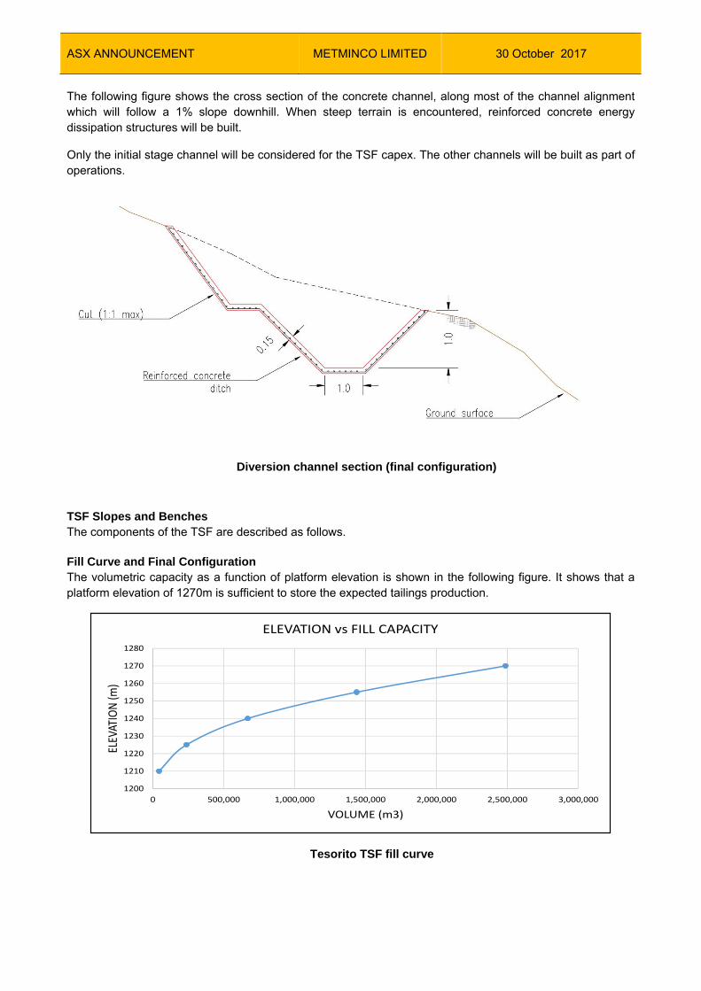
The following figure shows the cross section of the concrete channel, along most of the channel alignment which will follow a 1% slope downhill. When steep terrain is encountered, reinforced concrete energy dissipation structures will be built.
Only the initial stage channel will be considered for the TSF capex. The other channels will be built as part of operations.
Diversion channel section (final configuration)
TSF Slopes and Benches The components of the TSF are described as follows.
Fill Curve and Final Configuration The volumetric capacity as a function of platform elevation is shown in the following figure. It shows that a platform elevation of 1270m is sufficient to store the expected tailings production.
Tesorito TSF fill curve
1200
1210
1220
1230
1240
1250
1260
1270
1280
0 500,000 1,000,000 1,500,000 2,000,000 2,500,000 3,000,000
ELEV
ATION (m
)
VOLUME (m3)
ELEVATION vs FILL CAPACITY

ASX ANNOUNCEMENT METMINCO LIMITED
30 October 2017
The platform area vs elevation is shown in the following figure, where it can be observed that after the tailings elevation reaches the starter embankment crest there will be more than 10,000m2 of pad area for adequate spreading and compaction, while having additional area to temporarily store and handle wetter-than-optimum tailings.
Pad area vs. platform elevation
Instrumentation Planning and Monitoring
Instrumentation will be installed to monitor overall stability and deformation during operation of the TSF and all related structures including tailings deposit, starter dam, seepage pond/dike and water management structures. Instrumentation is to be maintained, replaced, added, extended and relocated during the development of the TSF; the proposed arrangement of instrumentation is shown in the following figure and explained as follows:
Survey monuments (benchmarks) will be placed at the following locations: o Downstream face of the seepage pond dike o Downstream face of the starter dam o Downstream face of the tailings deposit, these monuments will be installed as the tailings
deposit is raised by depositing and compacting filtered tailings.
A total of 25 monuments are recommended for the TSF. Once each sub-structure is built (starter dam, seepage pond dike, etc.) and the monument is installed an initial (“zero”) reading will be taken to provide initial X,Y,Z coordinates. After this initial reading, the monument will be monitored twice a week during the first month of operation. If no movements or deformations are observed readings can be taken on a bi-weekly basis.
Two slope inclinometers are recommended, one at the intermediate berm of the Tailings deposit (el. 1230 m) and a second inclinometer at the deposit´s maximum elevation (el. 1270 m). The inclinometer readings will allow to determine a complete profile of deformations and depth of shear surfaces (if any) to aid in determination of emergency actions. Bi-weekly readings are recommended once the device is installed.
As the inclinometers are recommended at elevations 1230m and 1270m, installation of these instruments will only be completed after year 5 of operation.
Piezometers:
1200
1210
1220
1230
1240
1250
1260
1270
1280
0 10,000 20,000 30,000 40,000 50,000 60,000 70,000 80,000 90,000
ELEVATION (m)
AREA (m2)
ELEVATION vs PAD AREA

ASX ANNOUNCEMENT METMINCO LIMITED
30 October 2017
o Vibrating wire piezometers (VWP) are recommended for the tailings and foundation
materials for evaluation of generation of pore pressures, saturation of the TMF and monitor the ground temperature. VWPs can be programmed to take automatic readings every six hours, and data can be collected on a bi-weekly basis. Recommended locations for VWP are:
Seepage Pond Dike crest – PZ-02 Seepage Pond – PZ-03 Starter dam Crest – PZ-04 Tailings Deposit intermediate berm (el. 1230m) – PZ-05 Tailings Deposit intermediate berm (el. 1250m) – PZ-06
The VWPs to be located over the tailings deposit will be installed once the deposit reaches the proposed elevation.
o Open pipe piezometers. At least two piezometers that allow water sampling are required, one upstream of the tailings deposit footprint (PZ-07) and a second open pipe piezometer downstream of the seepage pond dike (PZ-01). Open pipe piezometers will be built using PVC pipe with a minimum diameter of 2” to allow use of a bailer for water quality sampling.
A staff gauge will be installed at the seepage collection pond. This gauge will be read on a daily
basis to document water elevations.
Drone aerial fly-overs are to be completed on a monthly or bi-monthly basis (depending on the actual rate of TSF raise) to show the progression of the TSF growth, moist zones, and calculation of tailings and waste volume deposited and compacted.
The piezometers, slope inclinometers and survey monuments are to be monitored by the responsible party and at the frequency stated above and any other periods of extended rainfall or run-off. Immediate readings of all instrumentation will be carried out following a significant seismic or climatic event.
Data obtained from the monitoring devices (VWPs, Open pipe piezometers and inclinometers) and monitoring surveys will be compiled and analysed on a monthly basis, with the responsible party to submit a monthly instrumentation report.

ASX ANNOUNCEMENT METMINCO LIMITED
30 October 2017
Proposed instrumentation layout

ASX ANNOUNCEMENT METMINCO LIMITED
30 October 2017
Typical survey monument on soil
Soil Inclinometer
The piezometers, slope inclinometers and survey monuments are to be monitored by the responsible party and at the frequency stated above and any other periods of extended rainfall or run-off. Immediate readings of all instrumentation must be carried out following a significant seismic or climatic event.
Construction Considerations Quality Assurance (QA) for the TSF construction will consist of the following activities:
Testing of tailings material being placed in the TSF: o Moisture content (daily) o Grain size distribution (weekly) o Moisture-density relationship (monthly) o Shear strength (weekly using in-situ shear vane) o Concrete strength (as needed) o As-compacted density using sand cone and/or electrical or nuclear density gauge (daily)
On-Site supervision from Construction Management (daily) Review of topographical and instrumentation equipment data (bi-weekly)

ASX ANNOUNCEMENT METMINCO LIMITED
30 October 2017
Weekly records of laboratory and in-situ testing will be generated and submitted to the General Manager.
Bill of Quantities and Construction and Operations Costs
The estimated quantities for TSF construction include excavations and fills for starter embankment, water management structures, underdrains and ponds.
The capital costs include equipment and materials required for construction of the tailings pad, embankments, ponds and water management structures. Plant and decline earthworks and road improvement are excluded.
The following considerations were made:
Earthworks and concrete costs are typical in the Project area and are based on conversations with contractors
Additional to direct labour and equipment costs, the contractor will add the following items. These are typical charges and will vary depending on the amount of the bid and company, and can amount up to 30% of the direct costs:
o Administration o Taxes o Contingencies o Profit
Rock for embankment construction will be sourced from the initial decline development. A portable crusher should be provided to ensure an adequate gradation.
Concrete costs assume a batch plant will be installed on the Project site. Estimations do not include contractor mobilisation, contingency or indirects.
The following table summarises the CAPEX estimate:
The operational costs presented here include the TSF operation, and consider an outside contractor for supply of equipment, operators and other consumables for hauling the filter cake from the filter press area, spreading and compacting the materials in the TSF area.
No. Item Unit Quantity Unit cost US$ Subtotal US$
1 Bush and tree clearance within TSF basin ha 25 185.00 4,625.00
2 Embankments topsoil removal m3 50,000 1.50 75,000.00
3 Soil excavation m3 120,000 1.50 180,000.00
4 Rock excavation m3 5,000 5.75 28,750.00
5 Soil/rock haul and dump (<1km) m3‐km 345,000 0.10 34,500.00
6 Permanent diversion channel (concrete lined) lm 600 160.00 96,000.00
7 First stage diversion channel lm 1,435 50.00 71,750.00
8 Basin groundwater drains lm 600 80.00 48,000.00
9 Embankments subgrade preparation m3 3,500 20.00 70,000.00
10 Graded filter material for embankment faces m3 500 15.00 7,500.00
11 Embankments haul, place and compact selected fill m3 60,000 6.00 360,000.00
12 Pond basin preparation m3 2,000 20.00 40,000.00
13 HDPE pond liner (1.5mm) m2 4,500 7.00 31,500.00
14 Soil anchors for stabilization lm 8,000 65.00 520,000.00
15 Non woven Geotextile m2 15,000 2.50 37,500.00
16 900mm concrete culverts lm 100 300.00 30,000.00
17 24" pvc piping for construction water management lm 300 250.00 75,000.00
18 Revegetation m2 20,000 4.00 80,000.00
19 Monitoring and Reporting mo 18 20,000.00 360,000.00
20 Pond leak monitoring system no. 1 25,000.00 25,000.00
21 Excavated soil haulage to dump site (<1 km away) m3‐km 50,000 2.00 100,000.00
2,275,125.00

ASX ANNOUNCEMENT METMINCO LIMITED
30 October 2017
PERMITTING, ENVIRONMENTAL STUDIES AND SOCIAL AND COMMUNITY IMPACT PERMITTING Permitting The licensing process of mining projects requires either ANLA or CARDER to issue a licence and this is based on the annual volume of material to be exploited. For projects exploiting more than 2 Mt/y the responsibility will be with ANLA. Both ANLA and CAR can enforce project compliance with the terms of their licenses or permits. Once the administrative process has been initiated, the environmental authorities then issue environmental Terms of Reference (ToR) to which the license applications must adhere. The Miraflores Project EIS (2013) did not previously have an official ToR, instead, the baseline data collection and EIS development was progressed under a generic ToR for open pit mining. This generic ToR was issued by ANLA in 2012. In July 2016, a new ToR was issued by ANLA. The Project submitted a request to CARDER for an official ToR for the new underground Project concept. The new ToR was obtained in August 2017 and is being used as the basis for the ongoing environmental and social work. NGOs and the local communities have the opportunity to participate in the environmental administrative procedures leading up to the issuance of an environmental license. The environmental process will include participation of, and information to, all communities in the Project area including indigenous communities and Afro-descendant communities. Environmental Studies Environmental and social baseline studies were initiated in 2010, and expanded in 2012. However, with the termination of the Feasibility Study in 2013, most of the data collection programs were halted. These programs have now been reinitiated and modified in order to meet the data quality objectives associated with the revised mine plan and project layout. In order to perform construction and exploitation operations, the concession holder must obtain an environmental license or the approval of an existing Environmental Management Plan either from ANLA if the project exploits more than 2 Mt/y or from CARDER if mineral exploitation is less than 2 Mt/y. As of July 2017, Baseline Study and Environmental Impact Assessment programs have recommenced. The bulk of the Baseline activities previously completed will be used as background information, however, local regulations requires all environmental and social baseline data to be no older than 12 months since its collection, thus new monitoring programs are underway starting Q3 of 2017.
The monitoring and environmental inventories consist of:
Fauna and flora characterisation;
Underground and surface water characterisation;
Noise, vibration and air pollution; and
Potential contaminants from extracted minerals and stored tailings.
These data along with the mineralogical, geological, social and economic aspects of the new Project will be
used to elaborate the Environmental Impact Assessment, per the terms of reference supplied by the local
environmental agency CARDER in July 2017.
Social and Community Impact Permitting
NGOs and the local communities have the opportunity to participate in the environmental administrative procedures leading up to the issuance of an environmental license. The environmental process will include

ASX ANNOUNCEMENT METMINCO LIMITED
30 October 2017
participation of, and provision of information to, all communities in the Project area including indigenous communities and Afro-descendant communities.
According to Resolution 483 of 2015 of the Ministry of Interior, within the influence area of Miraflores there are two indigenous communities, the Embera Chamí community and the Embera Karambá community.
In this respect, the Embera Chamí Safeguard Plan highlights that the indigenous communities in Quinchía do not have any type of collective territory. On the contrary, they are scattered within the municipality, mainly in the villages of El Limon, Ensenillal, Manzanarez, Pomesia, Yarumal, Cartagueño, El Pencil, Curces, Hisana, Villa Nueva, Isambra, Quinchía VIejo, La Peña, EL Higo, Palo Grande, Buena Vista, El Provenir, Naranjal, Chorroseco, Santa Cecilia and Corozal.
Based on the characterisation completed on 2013, the majority of the people present in Quinchia (83%) declare they are from non-indigenous communities. Environmental impacts will be defined and negotiated with competent authorities once the study is submitted. These will be the result of the ongoing EIA and environmental baseline studies and will be published once available.
For the primary information, the results of the surveys undertaken in 2013 were used. This information will be updated when the new social baseline study is completed. For the study undertaken in 2013, the direct influence area of the Project included the villages of Miraflores, Guerrero, Aguas Claras, Veracruz, Agua Salada, La Esmeralda and Los Medios.
As a consequence of the presence of local communities such as farmers, indigenous groups (Embera Chamí and Embera Karambá) and informal miners on the Project influence area, a social management and community relationship strategy was developed in order to establish a relationship with these stakeholders. The socio-management and community relationship strategy has the following components:
Relationship and communications; socialisation of the exploration phase and community management.
Social and Community Development; training for employment and economic integration and strengthening of civic and social skills.
Institutional Strengthening; strengthening of the Departmental Table of Responsible Mining and Environmental Sustainability.
Negotiation of Agreements; agreement negotiations. Economic Dynamism: inclusion of the Project with informal miners, members of their families and
ethnic population who will be part of the workforce for the Project and promoting the development of productive projects and their integration into the value chain of the Company and/or the production chains in the region.

ASX ANNOUNCEMENT METMINCO LIMITED
30 October 2017
CAPITAL AND OPERATING COSTS
Scope of Estimate
Capital and operating cost estimates have been developed for an operation capable of treating 466,628 tonnes of ore per annum. Capital application will include:
A conventional underground operation;
A gold processing plant utilising a gravity and concentrate flotation flow sheet comprising of gravity separation and intensive leaching, conventional flotation and cyanide leach circuit with zinc precipitation for recovery of the precious metals; and
Support infrastructure and utilities.
The level of accuracy of the cost estimate for initial capital expenditure is within -10% to +15%. Costs are presented in United States dollars (US$) and are based on prices in effect during the second quarter of 2017 and do not include any escalation factors.
The capital estimate is only for capital costs from the commencement of the process plant design and construction award (Project sanction); the following are not included in the capital estimate:
All costs prior to Project sanction are excluded, including exploration, pre-feasibility and feasibility related studies (i.e. sunk costs);
All exploration and development drilling expenditures. Miraflores “owners’ costs” for Project development are included, however, Miraflores corporate costs, further study costs and Project ramp up costs are excluded (i.e. sunk costs);
Charges related to financing (e.g., fees, consultants, etc.);
Capitalised interests and standby fees from third-party lenders; and
Corporate overheads, other than that specifically identified, be it locally or internationally.
It is expected that materials, goods and services will be sought within Colombia where possible to minimise import tax/duty and minimise schedule risk, however, it is inevitable that some technologies/machinery and competencies are not available in Colombia (or much cheaper elsewhere), hence some goods and services will be imported. Costing used in the capital estimate has been on the basis of a number of items quoted in currency of origin, hence the requirement to define exchange rates. The estimate is based on US$ as this is a relatively hard currency when compared with the Colombian Peso, hence dampening exchange rate fluctuations. Exchange rates used to develop the costs are as follows:
US$1.00 = A$0.80 (Australian Dollar);
US$1.00 = €0.85 (Euro); and
US$1.00 = 3,000 COP (Colombian Pesos).
Capital Costs
The capital cost estimate developed for the Study is based upon an EPCM approach whereby Miraflores assumes general risk. As a result, the capital estimate does not include a contractor’s risk margin (for any portion to be let on a lump sum basis), nor does it include owner’s management reserve to cover risk range sensitivities (excluded project–specific risk and low probabilistic risk). The only margin included in the estimate is on EPCM rates for the EPCM contractor.
The total estimated cost of bringing the Project into production is US$71.8m excluding all contingency, which has been included in the financial analysis by Miraflores in Part 22 of the Technical Report.

ASX ANNOUNCEMENT METMINCO LIMITED
30 October 2017
The overall capital costs for the mining and process plant are summarised in the table below. This cost excludes the sunk costs incurred to date and costs of feasibility studies prior to and leading up to full project approval.
Initial and Sustaining Capital Cost Estimate
Cost Area Initial Capital
(US$ millions)
Sustaining Capital
Cost
(US$ millions)
Mining 14.0 16.5
Process Plant 46.3 1.4
TSF 2,3
Owners’ Costs 8.4 0.6
Power Line 0.8
Total Expenditure1 71.8 18.5
Miraflores owners’ capital costs are included with the mining, process plant and infrastructure capital cost estimate. The owners’ costs were generated by making provision for all personnel and expenses associated with the Project through pre-operations development up to the point of commissioning of the process plant. A contingency of US$6,120,008 (7.67% of Initial Capital Estimate) has been estimated for the Project development.
1 Excludes task specific contingency, taxes, royalties and risk costs

ASX ANNOUNCEMENT METMINCO LIMITED
30 October 2017
Mining Capital Costs
The LoM mine capital cost estimate for the Miraflores Project totals US$30.5 million and is summarised in the table below. The capital is broken down by initial capital required to start and develop the mine, and sustaining capital used to continue operations and LoM investments.
The capital expenditure estimate for the Project includes the following major items:
Description Initial Sustaining LoM
Decline Ramp Development
0.7 5.5 6.2
Drift & Cross-cut Development
2.0 ‐ 2.0
Raise Borer Development
‐ 2.9 2.9
VCR Development
‐ 0.8 0.8
Special Sections Development
0.3 3.8 4.1
Underground Mine Equipment
3.6 1.5 5.1
Stope Production
0.4 ‐ 0.4
G&A
1.2 ‐ 1.1
Services
1.3 ‐ 1.3
Infrastructure
4.5 2.0 6.5
Total 14.0 16.5 30.5
Source: Ausenco, 2017
LoM Capital Cost (US$ millions)
The capital expenditure for infrastructure and mine equipment is summarised in the following tables.
The capital cost estimate developed for this study includes the costs associated with the procurement, preliminary estimate of taxes and pre-operation required for all Project facilities.
The capital cost estimates include direct and indirect costs.
The decline ramp, ventilation development and special sections development (includes passing bays, sumps etc.) for the Project is capitalised and expensed over the LoM.

ASX ANNOUNCEMENT METMINCO LIMITED
30 October 2017
Description Initial Sustaining LoM
Access Portal
0.95 ‐ 0.95
Ventilation
2.7 0.8 3.6
Powder Magazine
0.1 ‐ 0.1
Electrical Distribution Network
0.37 0.4 0.77
Safety & Health
0.15 0.27 0.42
Industrial Water Network
0.04 ‐ 0.04
Dewatering
0.03 0.3 0.33
Communications
0.1 0.2 0.3
Other
0.04 0.04 0.09
Total 4.6 2.0 6.6
Source: Ausenco, 2017
Infrastructure capital costs (US$ millions)
Description Initial Sustaining LoM
Jumbo
0.65 ‐ 0.65
Longhole
0.44 0.98 1.42
LHD
0.53 0.36 0.89
FEL
0.04 ‐ 0.04
Low Profile Truck
0.63 ‐ 0.63
Telescopic Telehandler
0.1 ‐ 0.1
Bulldozer
0.11 ‐ 0.11
Grader
0.09 ‐ 0.09
Diesel Truck
0.05 ‐ 0.05
Truck Crane
0.03 ‐ 0.03
Diamond Drill
0.06 ‐ 0.06
Minor Equipment
0.85 0.13 0.98
Total 3.6 1.5 5.0
Source: Ausenco, 2017
Underground Mine Equipment capital costs (US$ millions)

ASX ANNOUNCEMENT METMINCO LIMITED
30 October 2017
Process Plant and Infrastructure Capital Costs
The process plant capital costs (including sustaining capital) by discipline are included in the table below.
Process Plant Capital Cost Summary by Discipline (US$ millions)
ITEM Materials &
Equipment
Installation
Freight
Subtotal
DIRECT COSTS
Earthworks 0 1.7 0 1.7
Civil works 0.4 1.3 0 1.8
Mechanical equipment 12.2 2.3 0.6 15.2
Platework 1.7 0.7 0.1 2.5
Structural steel 1.6 0.6 0.05 2.3
Electrical installations 4.2 2.0 0.3 6.5
Buildings 0.3 0.1 .01 0.4
Piping 2.0 1.6 0.1 3.8
Construction equipment 1.2 0.7 0.1 2.0
Total Direct Costs (Including Infrastructure) 23.6 11.1 1.4 36.2
Temporary construction facilities 0.1 0.06 0 0.2
Supervision and Construction Management 0.3 4.3 0 4.6
Project and procurement management 0.1 1.6 0 1.8
Engineering design 0.1 3.5 0 3.6
Vendor Commissioning 0.04 0.09 0 0.1
Commissioning 0 0.5 0 0.5
Initial fills 0.3 0 0 0.3
Insurance Spares 0.4 0 0.02 0.4
Total Indirect Costs 1.5 10.1 0.02 11.5
Owners’ Costs 9.0
TSF 2.3
Power Line 0.8

ASX ANNOUNCEMENT METMINCO LIMITED
30 October 2017
ITEM Materials &
Equipment
Installation
Freight
Subtotal
Process Plant, Infrastructure & Owners’
Costs TOTAL
25.1 21.2 1.4 59.8
Contingency 6.1
OVERALL TOTAL 65.9
Operating Costs
The operating cost estimate is considered to have an accuracy of between -10% and +15%, is presented in US dollars; and is based on prices obtained during the second quarter of 2017
Mine Operating Costs
Description US$/t-milled LoM (US$ millions) Drift & Cross Cut Development (4 m x 4 m) 5.19 22.4
Stope Production 7.88 34.1
Backfill 1.15 4.98
Mining Support 5.43 23.5
Services 5.84 25.3
Leasing Equipment 2.46 10.6
Total 27.94 120.9
Source: Ausenco, 2017
Underground mining operating costs

ASX ANNOUNCEMENT METMINCO LIMITED
30 October 2017
Processing and Infrastructure Operating Costs
Production Total Period
(LoM)
Tonnes Treated (t) 4,326,353
Gold (g/t) 3.29
Silver (g/t) 2.56
Cost Centre Unit Cost
US$/t
Crushing and Screening (including Reclaim) 2.35
Grinding, Classification and Gravity 5.29
Flotation 1.72
Concentrate Thickening & Leaching 1.02
Concentrate Residue Thickening and
Filtration 0.24
Gold and Silver Recovery 0.31
Tailings Thickening and Filtration 0.57
Detoxification 1.53
Reagent Mixing and Distribution 0.10
Water and Air Services (Including WTP) 0.67
Tailings Storage Facility 0.81
Workshop 0.08
Laboratory 0.51
Process Plant Specific Administration 6.16
Total - Processing Plant 21.35
General & Administration 4.35
TOTAL 25.71
LABOUR
Peak mine labour requirements are as follows;
Mining and mining maintenance: 115 personnel
Geology and Environment: 15 personnel
Processing and processing maintenance: 84 personnel
Management and Administration: 30 personnel
Total peak Labour: 244 personnel
The mine and processing plant will operate 24 hours per day 7 days per week. The crushing plant will operate 12 hours per day 5 days per week. Management, administration and professional staff will work 10 hours per day 5 days per week.

ASX ANNOUNCEMENT METMINCO LIMITED
30 October 2017
ECONOMIC ANALYSIS
Base Case Results - NPV, IRR, Payback
The table below is a summary of the base case financial outcomes for the Project, these calculations exclude contingency and sunk costs.
NPV, IRR and Payback for the base case After Tax NPV Value in US$ LoM After Tax Free Cashflow 150.0 million NPV@5% 96.1 million NPV@8% 72.3 million IRR (%) 25 Payback undiscounted in years 3.6
Project Implementation The Project milestones are envisaged to be the following:
Key Milestones For Project Implementation
Milestone Week After Commencement
Project kick off 1 Commencement of international and long lead procurement
3
Completion of FEED 15 Commencement of camp expansion 22 Mobilisation of earthworks contractor 25 Mobilisation of concrete contractor 32 Completion of detailed engineering 35 Commencement of SMP works 40 Mine equipment lease signed 47 Completion of concrete works 50 Mobilisation of E&I contractor 57 Mine development commences 64 Completion of procurement 65 Completion of SMP works 75 Completion of E&I works 75 Commencement of dry commissioning 75 Commencement of wet commissioning 78 Ore Commissioning Complete 86

ASX ANNOUNCEMENT METMINCO LIMITED
30 October 2017
RISKS AND RECOMMENDATIONS
A summary of the major risks includes:
Social impact studies are currently being underwritten by the university of Colombia. This
work needs to be completed and the social impact continued to be positively developed
within the Miraflores community;
Mining geotechnical and hydrology requires further understanding as the Project
develops; and
Process plant geotechnical results demonstrated reactive clays to depth in the process
plant area, ground improvement has been included and options for plant locations should
be considered to mitigate inherent risks.
GLOSSARY OF TECHNICAL TERMS "assay"
The laboratory test conducted to determine the proportion of a mineral within a rock or other material. For gold, usually reported as the grams of the mineral (i.e. gold) per tonne of rock.
“basalt” A dark-coloured, fine-grained extrusive igneous rock composed of plagioclase feldspar, pyroxene, and magnetite, with or without olivine and not more than 53 per cent. SiO2.
"breccia" Breccia is a rock classification, comprises millimetre to metre-scale rock fragments cemented together in a matrix, there are many sub-classifications of breccias.
"cut-off" the grade threshold above which a mineral material is considered potentially economic
"CIM" The reporting standard adopted for the reporting of the Mineral Resources is that defined by the terms and definitions given in the terminology, definitions and guidelines given in the Canadian Institute of Mining, Metallurgy and Petroleum (CIM) Standards on Mineral resources and Mineral Reserves (December 2005) as required by NI 43-101. The CIM Code is an internationally recognised reporting code as defined by the Combined Reserves International Reporting Standards Committee.
“concentrate” Metal ore once it has been through milling and concentration so that it is ready for chemical processing or smelting.
"grade" The proportion of a mineral within a rock or other material. For gold mineralisation this is usually reported as grams of gold per tonne of rock (g/t).
"g/t" grams per tonne; equivalent to parts per million ('ppm').

ASX ANNOUNCEMENT METMINCO LIMITED
30 October 2017
"Indicated Resource" An "Indicated Mineral Resource" is that part of a Mineral
Resource for which quantity, grade or quality, densities, shape and physical characteristics, can be estimated with a level of confidence sufficient to allow the appropriate application of technical and economic parameters, to support mine planning and evaluation of the economic viability of the deposit. The estimate is based on detailed and reliable exploration and testing information gathered through appropriate techniques from locations such as outcrops, trenches, pits, workings and drill holes that are spaced closely enough for geological and grade continuity to be reasonably assumed.
"Inferred Resource" An "Inferred Mineral Resource" is that part of a Mineral Resource for which quantity and grade or quality can be estimated on the basis of geological evidence and limited sampling and reasonably assumed, but not verified, geological and grade continuity. The estimate is based on limited information and sampling gathered through appropriate techniques from locations such as outcrops, trenches, pits, workings and drill holes.
“JORC Code” The Australasian Code for Reporting of Exploration Results, Mineral Resources and Ore Reserves (2012 edition), published by The Joint Ore Reserves Committee of the Australasian Institute of Mining and Metallurgy, Australian Institute of Geoscientists and Minerals Council of Australia (“JORC”).
"Measured Resource" A "Measured Mineral Resource" is that part of a Mineral Resource for which quantity, grade or quality, densities, shape, and physical characteristics are so well established that they can be estimated with confidence sufficient to allow the appropriate application of technical and economic parameters, to support production planning and evaluation of the economic viability of the deposit. The estimate is based on detailed and reliable exploration, sampling and testing information gathered through appropriate techniques from locations such as outcrops, trenches, pits, workings and drill holes that are spaced closely enough to confirm both geological and grade continuity.
“Mineral Reserve” That part of a Mineral Resource that has been demonstrated to be economically extractable.
"Mineral Resource" A "Mineral Resource" is a concentration or occurrence of diamonds, natural solid inorganic material, or natural solid fossilized organic material including base and precious metals, coal, and industrial minerals in or on the Earth's crust in such form and quantity and of such a grade or quality that it has reasonable prospects for economic extraction. The location, quantity, grade, geological characteristics and continuity of a Mineral Resource are known, estimated or interpreted from specific geological evidence and knowledge.
“Mineralisation” The process by which minerals are introduced into a rock.

ASX ANNOUNCEMENT METMINCO LIMITED
30 October 2017
More generally, a term applied to accumulations of economic or related minerals in quantities ranging from weakly anomalous to economically recoverable.
"open pit mining" A method of extracting minerals from the earth by excavating downwards from the surface such that the ore is extracted in the open air (as opposed to underground mining).
“porphyry” A medium to coarse-grained intrusive, felsic, igneous rock which is conspicuously porphyritic, containing more than 25 per cent phenocrysts by volume. The phenocryst mineral is usually alkali feldspar.
“Probable Reserve” according to the JORC Code, the economically mineable part of a Measured and/or Indicated Mineral Resource. It is inclusive of diluting materials and allows for losses that may occur when the material is mined. Appropriate assessments, which may include feasibility studies, have been carried out, including consideration of, and modification by, realistically assumed mining, metallurgical, economic, marketing, legal, environmental, social and government factors. These assessments demonstrate at the time of reporting that extraction is reasonably justified.
“Proved Reserve” according to the JORC Code, the economically mineable part of a Measured Mineral Resource. It is estimated with a high level of confidence. It is inclusive of diluting materials and allows for losses that may occur when the material is mined Appropriate assessments, which may include feasibility studies, have been carried out, including consideration of, and modification by, realistically assumed mining, metallurgical, economic, marketing, legal, environmental, social and government factors. These assessments demonstrate at the time of extraction is reasonably justified.
“underground mining” extraction of minerals from the Earth’s crust using a system of underground mine workings.
Abbreviations
AACE Association for the Advancement of Cost Engineering International
AAS atomic absorption spectrometry
Ag Silver
As Arsenic
Au Gold
Cu Copper
CoG Cut off Grade
Fe Iron

ASX ANNOUNCEMENT METMINCO LIMITED
30 October 2017
g/t grams per metric tonne
h hour(s)
ha Hectare
Hg Mercury
ICMC International Cyanide Management Code
km Kilometres
l Litres
M million(s)
Mt/a Million tonnes per annum
m Metres
mAMSL meters above mean sea level
P&ID Piping and Instrumentation Diagram
Pb Lead
QA/QC quality assurance and quality control
RC reverse-circulation drilling method
RQD rock quality designation
S Sulphur
Sb antimony
ºT degrees relative to true north
t Tonnes
t/a tonnes per annum
t/d or tpd tonnes per day
t/h tonnes per hour
TSF Tailings Storage Facility
Zn Zinc
William Howe Managing Director

ASX ANNOUNCEMENT METMINCO LIMITED
30 October 2017
For further information, please contact:
METMINCO LIMITED
Brian Jones Office: +61 (0) 2 9460 1856
NOMINATED ADVISOR AND BROKER
RFC Ambrian
Australia
Will Souter / Alena Broesder Office: +61 (0) 2 9250 0000
United Kingdom
Charlie Cryer Office: +44 (0) 20 3440 6800
JOINT BROKER
SP Angel Corporate Finance LLP (UK)
Ewan Leggat Office: +44 (0) 20 3470 0470
PUBLIC RELATIONS
Camarco
United Kingdom
Gordon Poole / Nick Hennis Office: + 44 (0) 20 3757 4997
Media + Capital Partners
Australia
Luke Forrestal Office: +61 (0) 411 479 144
Competent Persons Statement
The information provided in this announcement that relates to Mineral Reserves of the Miraflores Gold Project is based on information compiled by Mr Boris Caro. Mr Caro, a Qualified Person for JORC (2012 Edition) compliant statements, reviewed the technical information presented in this document.
Mr Caro has sufficient experience that is relevant to the style of mineralisation and type of mineral deposit under consideration, and to the activity which was undertaken, to make the statements found in this report in the form and context in which they appear. Mr Caro has consented to be named in this announcement and inclusion of information attributed to him in the form and context in which it appears herein.
Market Abuse Regulation (MAR) Disclosure
The information communicated in this announcement includes inside information for the purposes of Article 7 of Regulation 596/2014.
Forward Looking Statement All statements other than statements of historical fact included in this announcement including, without limitation, statements regarding future plans and objectives of Metminco are forward-looking statements. When used in this announcement, forward-looking statements can be identified by words such as ‘’anticipate”, “believe”, “could”, “estimate”, “expect”, “future”, “intend”, “may”, “opportunity”, “plan”, “potential”, “project”, “seek”, “will” and other similar words that involve risks and uncertainties.

ASX ANNOUNCEMENT METMINCO LIMITED
30 October 2017
These statements are based on an assessment of present economic and operating conditions, and on a number of assumptions regarding future events and actions that, as at the date of this announcement, are expected to take place. Such forward-looking statements are not guarantees of future performance and involve known and unknown risks, uncertainties, assumptions and other important factors, many of which are beyond the control of the Company, its directors and management of Metminco that could cause Metminco’s actual results to differ materially from the results expressed or anticipated in these statements. The Company cannot and does not give any assurance that the results, performance or achievements expressed or implied by the forward-looking statements contained in this announcement will actually occur and investors are cautioned not to place undue reliance on these forward-looking statements. Metminco does not undertake to update or revise forward-looking statements, or to publish prospective financial information in the future, regardless of whether new information, future events or any other factors affect the information contained in this announcement, except where required by applicable law and stock exchange listing