mm320 manual covers - edge technologies · then pull up and turn the knob “b” to set the ......
TRANSCRIPT


MINUTEMAN 320 HYDRODYNAMIC AUTOMATIC BAR FEEDER
MM-320
MANUAL FOR USE AND MAINTENANCE REV. 9 DATE:2012/12/10 COD:BMM09103032
S/H

CONTENT INDEX MM-320
I
CONTENT INDEX
1 GENERAL INFORMATION
1.1 Contents of manual ----------------------------------------------------------------------- 1-1
1.2 Name plate --------------------------------------------------------------------------------- 1-2
1.3 Technical Support ------------------------------------------------------------------------- 1-2
2 TECHNICAL DATA
2.1 Instruction ----------------------------------------------------------------------------------- 2-1
2.2 Machine footprint -------------------------------------------------------------------------- 2-2
2.3 Machine specifications ------------------------------------------------------------------ 2-2
2.4 Compressed air supply ------------------------------------------------------------------ 2-3
2.5 Guide channel sizes ---------------------------------------------------------------------- 2-4
2.6 Collet sizes ---------------------------------------------------------------------------------- 2-5
3 TRANSPORTATION
3.1 Packaging ----------------------------------------------------------------------------------- 3-1
3.2 Transportation and lifting ---------------------------------------------------------------- 3-2
3.3 Installation area ---------------------------------------------------------------------------- 3-3
4 INSTALLATION
4.1 Bar feeder – Installation ----------------------------------------------------------------- 4-1
4.2 Leveling ------------------------------------------------------------------------------------- 4-1
4.3 Height adjustment ------------------------------------------------------------------------ 4-2
4.4 Initial position ------------------------------------------------------------------------------ 4-3
4.5 Adjustment of center -------------------------------------------------------------------- 4-4
4.6 Securing and fastening ------------------------------------------------------------------ 4-6
4.7 Installing accessories -------------------------------------------------------------------- 4-7
4.8 Guide channel lubrication --------------------------------------------------------------- 4-15

CONTENT INDEX MM-320
II
CONTENT INDEX
5 ADJUSTMENT AND SETTING
5.1 Barfeed components ---------------------------------------------------------------------- 5-1
5.2 Loading device ----------------------------------------------------------------------------- 5-2
5.3 Installation and adjustment - moveable anti-vibration device (MAVD) ------- 5-3
5.4 Feeding Chain ------------------------------------------------------------------------------ 5-4
6 OPERATION AND DESCRIPTION 6.1 Material preparation ---------------------------------------------------------------------- 6-1
6.2 Operator interface description ---------------------------------------------------------- 6-2
6.3 Pneumatic valve layout ------------------------------------------------------------------ 6-7
6.4 Parameter list and description ---------------------------------------------------------- 6-9
6.5 Alarm list ------------------------------------------------------------------------------------- 6-23
7 MAINTENANCE
7.1 General maintenance -------------------------------------------------------------------- 7-1
7.2 Regular maintenance -------------------------------------------------------------------- 7-2
8 TROUBLESHOOTING
8.1 Troubleshooting issues ------------------------------------------------------------------- 8-1
8.2 Troubleshooting frame -------------------------------------------------------------------- 8-1 8.3 Troubleshooting pusher collet ---------------------------------------------------------- 8-1 8.4 Troubleshooting feeding mechanism ------------------------------------------------- 8-1
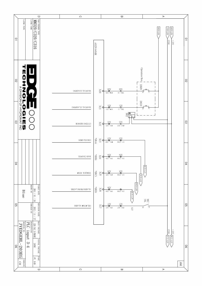
9 SCHEMATIC
9.1 Schematic ------------------------------------------------------------------------------------- 9-110 PARTS LIST
10.1 Parts List -------------------------------------------------------------------------------------- 10-1

1. GENERAL INFORMATION MM-320
1-1
1. GENERAL INFORMATION
Please read the Manual carefully before operating bar feeder.
1.1 Contents of manual The feeder manufacturer provides this manual, which is an essential part of the integrated product. Please act in accordance to the indications of this manual in order to assure operators’ safety as well as the machines, to greatly achieve economic efficiency and to get the best results out of the machine. The important parts are printed in boldface, and include the following marks:
Warning: Hazard! It is possible to be seriously hurt, please be careful.
Watch out-Precautions: To prevent accident or the loss of property, you should take precautions.
Important information: Special important know-how information
Please refer to the table of contents, you will quickly find the information you need.
The marks shown in this manual means that the machine should be operated by aqualified and experienced operator.

1. GENERAL INFORMATION MM-320
1-2
1.2 Name Plate
A. Name of manufacturer
B. Model(Type)
C. Serial Number
D. Manufacture Date
E. Weight of Machine
F. Pneumatic Pressure
G. Rated Voltage
H. Control Voltage
I. Full Load Current
J. Power
K. Short Circuit Rating L. Wiring Drawing Number
INFORMATION:When inquiring about service or ordering parts, please reference the serial number (D).
1.3 Technical Support For technical support, contact the service center in the appendix at anytime or refer to the name plate on the bar feeder.

2. TECHNICAL DATA MM320
2-1
2. TECHNICAL DATA
2.1 Instruction
The Minuteman 320 is an automatic hydrodynamic bar feeder designed for fixed and
sliding headstock CNC and CAM lathes, to automatically feed and load material. A PLC
controls the bar feeder operations with the lathe using an operator interface to program
application settings. Manual and automatic operation are made easy through the remote
operators pendant.
The bar feeder can feed round, shaped and many other forms of material. Hydraulic oil
is pumped into a completely closed guide channel reducing noise, vibration and
temperature during material rotation at high speed. Adjustable roller guides on the front of
the barfeed (and headstock for sliding headstock lathes) are further used to reduce noise
and vibration by eliminating gaps between the guide channel and material allowing a large
range of material diameters to be used in one guide channel.
2. DATA OF TECHNIQUE MM-320
2-2
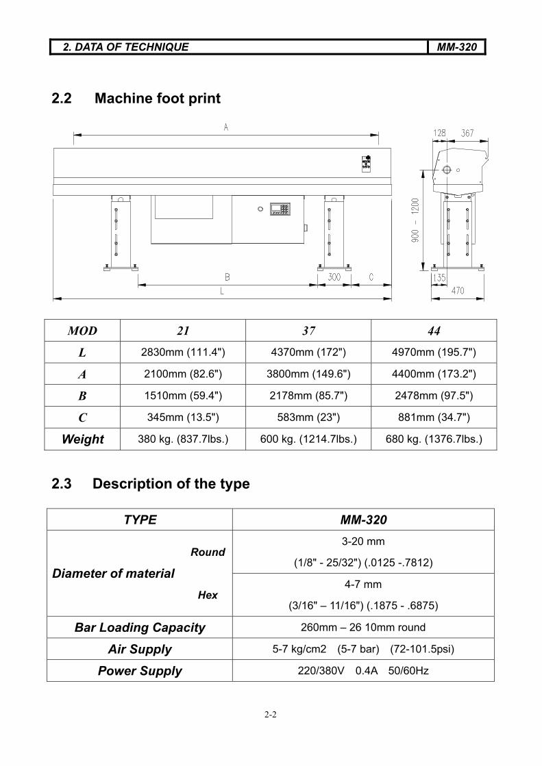
2.2 Machine foot print
2.3 Description of the type
MOD 21 37 44
L 2830mm (111.4") 4370mm (172") 4970mm (195.7")
A 2100mm (82.6") 3800mm (149.6") 4400mm (173.2")
B 1510mm (59.4") 2178mm (85.7") 2478mm (97.5")
C 345mm (13.5") 583mm (23") 881mm (34.7")
Weight 380 kg. (837.7lbs.) 600 kg. (1214.7lbs.) 680 kg. (1376.7lbs.)
TYPE MM-320
Round3-20 mm
(1/8" - 25/32") (.0125 -.7812) Diameter of material
Hex4-7 mm
(3/16" – 11/16") (.1875 - .6875)
Bar Loading Capacity 260mm – 26 10mm round
Air Supply 5-7 kg/cm2 (5-7 bar) (72-101.5psi)
Power Supply 220/380V 0.4A 50/60Hz

2. TECHNICAL DATA MM320
2-3
2.4 Compressed air supply
2.4.1 Tube for compressed air supply unit must be bigger than 8mm. Pressure must be
over 6 bar or 80 psi, consumption about 50L/H.
2.4.2 Install the air supply into “A”. Then pull up and turn the knob “B” to set the pressure
at 6 bar or 80 psi.
2.4.3 Control air lubrication cylinder , adjust (C), 1-2 drops 1000 L air if necessary.
2.4.4 Lubrication (D), viscosity 32 Cat , temperature 40�, ISO VG type
Lubricant
BP ENERGOL HLP32 AGIP OSO 32 MOBIL DTE 24 ESSO NUTO H32
C
A
DB

2. TECHNICAL DATA MM320
2-4
2.5 Guide channel sizes
Diameter of Bar (MM)
Max. Type Diameter of Guide
Channel
Diameter of Bar
Pusher Min.
8 7.5 3 6.4 7.5
12 14
12.7* 3 10 12
15* 15
16 16 18
17*
3 13
16
19* 16 19
20 18 20 22
21*
3
18 21
21* 18 21
22* 18 22
MM-320
24
23
3
20.6 23
* Special pusher O.D.’s for specific spindle I.D.’s (Application based)

2. TECHNICAL DATA MM320
2-5
2.6 Collet Sizes
ØA ØF M5x.50 ØF M7x0.75 ØF M8x1.0 ØF M8x1.0 ØF M8x1.0 ØF M10x1.0 ØF M10x1.0 ØF M10x1.0
mm in 7.5mm OD 12mm OD 15mm OD 16mm OD 18mm OD 20mm OD 22mm OD 23mm OD
1.6 ICOLT075160 ICOLT120160 ICOLT150160
2
2.4 3/32” ICOLT075240 ICOLT120240 ICOLT150240
2.5
2.8 7/64” ICOLT075280 ICOLT120280 ICOLT150280
3
3.2 1/8” ICOLT075320 ICOLT120320 ICOLT150320 ICOLT200320
3.5
3.6 9/64” ICOLT075360 ICOLT120360 ICOLT150360 ICOLT200360
3.8
4 5/32” ICOLT075400 ICOLT120400 ICOLT150400 ICOLT200400
4.4 11/64” ICOLT075440 ICOLT120440 ICOLT150440 ICOLT200440
4.5
4.6
4.8 3/16” ICOLT075480 ICOLT120480 ICOLT150480 ICOLT200480
5
5.2 13/64” ICOLT075520 ICOLT120520 ICOLT150520 ICOLT200520
5.5
5.6 7/32” ICOLT075560 ICOLT120560 ICOLT150560 ICOLT200560
5.7
5.9
Collet
Bar size Ex: Ø12�1200
Ø22.5�2250
Outside diameter
Metric thread right hand
ICOLT121200

2. TECHNICAL DATA MM320
2-6
ØA ØF M5x.50 ØF M7x0.75 ØF M8x1.0 ØF M8x1.0 ØF M8x1.0 ØF M10x1.0 ØF M10x1.0 ØF M10x1.0
mm in 7.5mm OD 12mm OD 15mm OD 16mm OD 18mm OD 20mm OD 22mm OD 23mm OD
6 15/64� ICOLT075600 ICOLT120600 ICOLT150600 ICOLT200600
6.2
6.4 1/4� ICOLT075640 ICOLT120640 ICOLT150640 ICOLT200640
6.5
6.6
7 ICOLT120700 ICOLT150700 ICOLT200700
7.1
7.2 9/32� ICOLT120720 ICOLT150720 ICOLT200720
7.5
7.6 19/64�
8 5/16� ICOLT120800 ICOLT150800 ICOLT200800
8.3
8.4 21/64� ICOLT120840 ICOLT150840 ICOLT200840
8.5
8.7
8.8 11/32� ICOLT120880 ICOLT150880 ICOLT200880
8.9
9
9.1 23/64� ICOLT120910 ICOLT150910 ICOLT200910
9.3
9.5 ICOLT120950 ICOLT150950 ICOLT200950
9.6 3/8� ICOLT120960 ICOLT150960 ICOLT200960
10 25/64� ICOLT121000 ICOLT151000 ICOLT201000
10.25
10.4 13/32� ICOLT121040 ICOLT151040 ICOLT201040
10.5
10.7
10.8 27/64� ICOLT121080 ICOLT151080 ICOLT201080
11
11.25 7/16� ICOLT151120 ICOLT201120
11.5
11.7 13/64�
12 ICOLT151200 ICOLT201200
12.25

2. TECHNICAL DATA MM320
2-7
ØA ØF M5x.50 ØF M7x0.75 ØF M8x1.0 ØF M8x1.0 ØF M8x1.0 ØF M10x1.0 ØF M10x1.0 ØF M10x1.0
mm in 7.5mm OD 12mm OD 15mm OD 16mm OD 18mm OD 20mm OD 22mm OD 23mm OD
12.5 31/64 ICOLT151250 ICOLT201250
12.7 1/2 ICOLT151270 ICOLT161270 ICOLT181270 ICOLT201270
13 ICOLT161300 ICOLT181300 ICOLT201300
13.5 ICOLT151350 ICOLT161350 ICOLT181350 ICOLT201350
14 ICOLT161400 ICOLT181400 ICOLT201400
14.2 9/16 ICOLT161420 ICOLT181420 ICOLT201420
14.5
14.7 ICOLT181470 ICOLT201470
15
15.2
15.5 ICOLT181550 ICOLT201550
15.7 ICOLT181570 ICOLT201570
16 5/8 ICOLT181600 ICOLT201600 ICOLT221600 ICOLT231600
16.2 41/64
16.5 ICOLT201650
16.7
17 ICOLT201700
17.2 ICOLT201720
17.5 11/16 ICOLT201750
17.7
18 45/64 ICOLT201800 ICOLT221800 ICOLT231800
18.2 ICOLT201820 ICOLT221820 ICOLT231820
18.5
18.7 ICOLT201870 ICOLT221870 ICOLT231870
19 3/4 ICOLT221900 ICOLT231900
19.25
19.5
19.75
20 ICOLT222000 ICOLT232000
20.25
20.5
20.6 ICOLT222060 ICOLT232060
21 ICOLT222100 ICOLT232100

3. TRANSPORTATION MM320
3-1
3. TRANSPORTATION
�� Hazard-warning: Transportation and lifting (please refer to the item 3.2.1 of following weight table)
Make sure the crane, forklift or other related tools can take the weight.
Using the proper equipment to move and lift the machine should be undertaken by
experienced personnel.
3.1 Packaging
There are three kinds of bar feeder packaging:
A. Unpacked:
B. On the pallet: Put the feeder on the pallet and wrap PE membrane around the
feeder.
C. Packing with wooden box: The Feeder was packed with wooden box and wrap
PE membrane around the box.
A. B. C.

3. TRANSPORTATION MM-320
3-2
3.2 Transportation and hoist 3.2.1 Unpacking
Putting two steel bars (Diameter 30mm,length: 1M) under the bar feeder, using suitable steel ropes which are able to bear the weight to hoist.
3.2.2 On the pallet
Using suitable steel ropes which is able to
bear the weight to hoist the bar feeder.
3.2.3 Packing with wooden box
Using suitable steel ropes which is able to
bear the weight to hoist the bar feeder.
MM-320-21 380 kg. (837.7lbs.)
MM-320-37 600 kg. (1214.7lbs.)
MM-320-44 680 kg. (1376.7lbs.)

3. TRANSPORTATION MM-320
3-3
DF
E
3.3 Installation area In order to fix the feeder securely, the floor must be flat and firm.
According to the operation of the feeder to reserve a suitable area in advance.
Area (D-operator area) (E-supply area) (F-remnant material area)
The space must be enough to avoid the feeder caused crashed by the operator.
The area of installation needs to have suitable lighting, outlet and compressed air
joint.
The feeder can’t adapt to explosive surrounding.
List 1. Size of appearance
Type Size A
21 2830
37 4370 MM-320
44 4970

4. INSTALLATION MM320
4-1
4. INSTALLATION
4.1 Bar feeder - Installation Before installing the bar feeder, the spindle of the lathe must be level and the lathe
anchored to the ground.
4.2 Leveling
4.2.1 Install leveling screws (1) and nuts (2) in both front and back legs
4.2.2 Place one leveling pad (3) under each screw
4.2.3 Run screw down into leveling pad. Once touching rotate screw two revolutions.
4.2.4 Level stands.

4. INSTALLATION MM320
4-2
4.3 Height adjustment
4.3.1 Loosen the screws (1).
4.3.2 Adjust the screw 2 up or down to achieve correct height. Adjust the barfeed
height to center the channel to the lathe spindle.
1
2

4. INSTALLATION MM320
4-3
4.4 Initial position
The set distance from the bar feed to the lathe is 1346 mm (53 inches). Measure
from the face of the lathe collet to the first anti-vibration device channel support
block face (See inset A). For sliding headstock lathes make sure headstock has
gone to Z+ over travel limit toward the guide bushing. For lathes that have both a
fixed headstock and sliding headstock modes set Z axis at the maximum distance
away from the bar feeder.
1346mm (53 inches)
Channel support block face
First anti-vibration device
A

4. INSTALLATION MM320
4-4
4.5 Adjustment of center
In order to achieve a correct alignment, prepare a nylon string 1.27mm.(.050�).
Pull the nylon string from the lathe (A) to the end of the bar feeder (B).
See 4.5.1
A
B

4. INSTALLATION MM320
4-5
4.5.1
Take push bar out and insert centering
plug (comes with bar feeder), pull the
nylon string from the lathe A, to the end of
the bar feeder B.
4.5.2
Choose proper plug size for lathe collet,
insert and close lathe collet, move lathe Z
axis to –Z over travel, pull the nylon string
tight and secure in place.
(Hole thru plug 1.32mm (.052�)
4.5.3 Directional adjusting
Use a ruler or centering device to check
the center of the nylon string, nose adapter
(C), and spindle (D). The distance of the
four directions is to be within 0.15 mm.
Note: As alignment is adjusted make sure distance from bar feeder to lathe does not change.
B
CD
A
4. INSTALLATION EDGE12
4-6
2
1
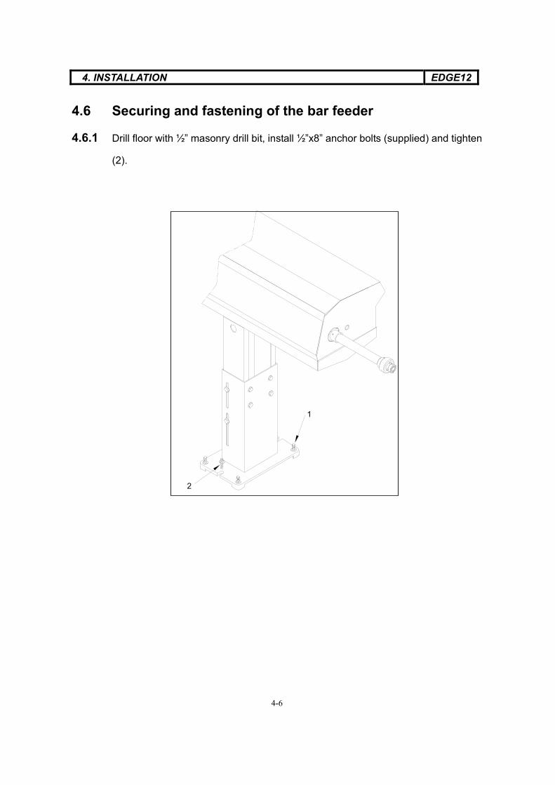
4.6 Securing and fastening of the bar feeder
4.6.1 Drill floor with ½” masonry drill bit, install ½”x8” anchor bolts (supplied) and tighten
(2).

4. INSTALLATION EDGE12
4-7
4.7 Installation accessories
4.7.1 Movable anti-vibration
The anti-vibration device is mounted at the end of the lathe spindle with mounting
hardware supplied.
The moveable anti-vibration device (MAVD) is pre aligned and assembled at the
factory according to lathe model. Lathe adapter plate (A), rollers (B) and nose plate
(C) are aligned along line (D) to ensure rollers hold bar stock on center with spindle.
With many different lathe designs, the lathe adapters connecting the MAVD to the
lathe may not allow for a direct bolt up. This will require the installer to align the
MAVD on center to the lathe spindle with alignment string provided. Pull string
using same steps in barfeed alignment, then with scale or alignment tool, align
lathe adapter plate which will move rollers and nose adapter plate all together.
D A B C

4. INSTALLATION EDGE12
4-8
Lathe adapter will slide over round casting on back on spindle. EX: Citizen – A16, A20, C16, K16, Star – SA12, SA16, SB16, SE16, SR10J, SR16, SR20, SV12, SV20 Tsugami – BN20, BW12
Lathe adapter will bolt up to lathe casting on center with spindle. Another adapter mounted to plate will align inside bolted up adapter. EX: Citizen – B20, L16, L20 Tsugami – BE19, BU12, BU20,
Lathe adapter will bolt up to bracketry supplied by dealer. Bracketry has to be aligned to spindle first. MAVD will then be direct bolt up to lathe bracketry. EX: Tsugami – BS19, BS20

4. INSTALLATION EDGE12
4-9
Lathe brackets that comes with barfeed, whole MAVD will have to be aligned at lathe adapter plate using string alignment method. Once tightened whole MAVD and brackets will be aligned. EX: Hanwha – SL20HP, XD20H KSI – SA12, SA20, SQC20 Nexturn – SA20 Nomura – NN20YB

4. INSTALLATION EDGE12
4-10
4.7.2 Synchronization connecting rod:
The synchronization connecting rod allows the mechanical connection between
lathe and barfeed which allows synchronized movement between the lathe z axis,
material, and barfeed pusher when lathe collet is closed.
Installation:
Move lathe Z axis to –Z over travel position.
Thread threaded rod (A) into swivel (B).
Measure from back side of plate (C) to
face of plate(D) and subtract 12.7mm (.500�).
With measurement, measure from point (E)
on swivel back along threaded rod (A), then
cut to length. Thread threaded rod (A) flush
with back side of plate (C) and tighten
nut (F) as shown.
Connect adapter (G) to swivel (B) and
tighten. Connect adapter (G) to square
synchronization rod (H) with screws supplied.
Gap (I) should be approximately 12.7mm
(.500”). Move lathe Z axis forward and
back checking for smooth operation and
clearance of synchronization rod (H),
adapter (G) and threaded rod (A).
C
F
D
I
E B A
H G

4. INSTALLATION EDGE12
4-11
4.7.3 Fixed front nose:
Cut nose to length to fit between barfeed and lathe. Oil recovery unit should fit up
to lathe coolant collector, covering barstock .
4.7.4 Telescopic front nose:
The telescoping nose allows the barstock and pusher to be supported and
protected during the full stroke of the lathes Z axis movement. It is connected
from the bar feeder to the adapting nose plate on the movable anti-vibration device
mounted on the back of the lathe spindle.
Installation:
Move lathe Z axis to –Z over travel position. Measure from face of nose adapter (A)
on bar feeder to inside shoulder (B) of moveable anti-vibration device on lathe.
Note measurement (#1).
Move lathe Z axis to +Z over travel position toward guide bushing. Measure from
face of nose adapter (A) on bar feeder to inside shoulder (B) of moveable
anti-vibration device on lathe. Note measurement (#2).
If lathe has a chuck change position closer to the guide bushing than +Z over
travel, measure to chuck change position.
A
B
4. INSTALLATION EDGE12
4-12
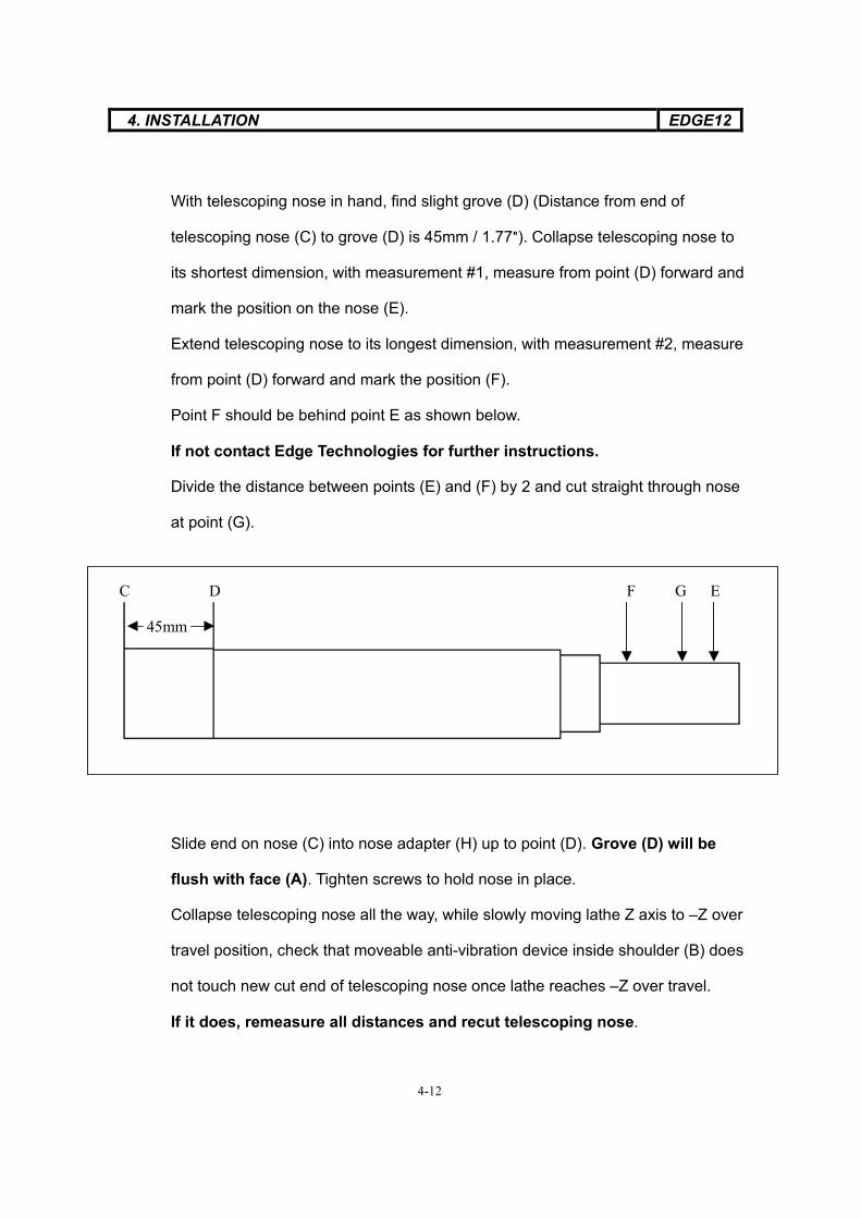
With telescoping nose in hand, find slight grove (D) (Distance from end of
telescoping nose (C) to grove (D) is 45mm / 1.77�). Collapse telescoping nose to
its shortest dimension, with measurement #1, measure from point (D) forward and
mark the position on the nose (E).
Extend telescoping nose to its longest dimension, with measurement #2, measure
from point (D) forward and mark the position (F).
Point F should be behind point E as shown below.
If not contact Edge Technologies for further instructions.
Divide the distance between points (E) and (F) by 2 and cut straight through nose
at point (G).
Slide end on nose (C) into nose adapter (H) up to point (D). Grove (D) will be
flush with face (A). Tighten screws to hold nose in place.
Collapse telescoping nose all the way, while slowly moving lathe Z axis to –Z over
travel position, check that moveable anti-vibration device inside shoulder (B) does
not touch new cut end of telescoping nose once lathe reaches –Z over travel.
If it does, remeasure all distances and recut telescoping nose.
45mm
C D F G E

4. INSTALLATION EDGE12
4-13
Move lathe Z axis to +Z over travel or chuck change position and check that new
cut end of telescoping nose touches inside shoulder (B) on moveable anti-vibration
device.
If it does not, the nose has been cut to short, contact Edge Technologies for
further instructions.
Install cut end of telescoping nose to inside shoulder (B) of moveable anti-vibration
device and secure with screws.
H
Telescoping nose installed and collapsed completely
Telescoping nose installed and extended completely

4. INSTALLATION EDGE12
4-14
4.7.5 Oil tray:
Slide nose (A) through ring (B) on oil tray (C). Attach oil tray to front plate of bar
feeder. Slide inner tray (D) all the way back toward bar feeder. Move lathe Z axis to
+Z over travel. Slide inner tray toward moveable anti-vibration device (E) until
there is a gap of 3-5mm. Lock tray in place at ring.
A B
C D E
4. INSTALLATION EDGE12
4-15
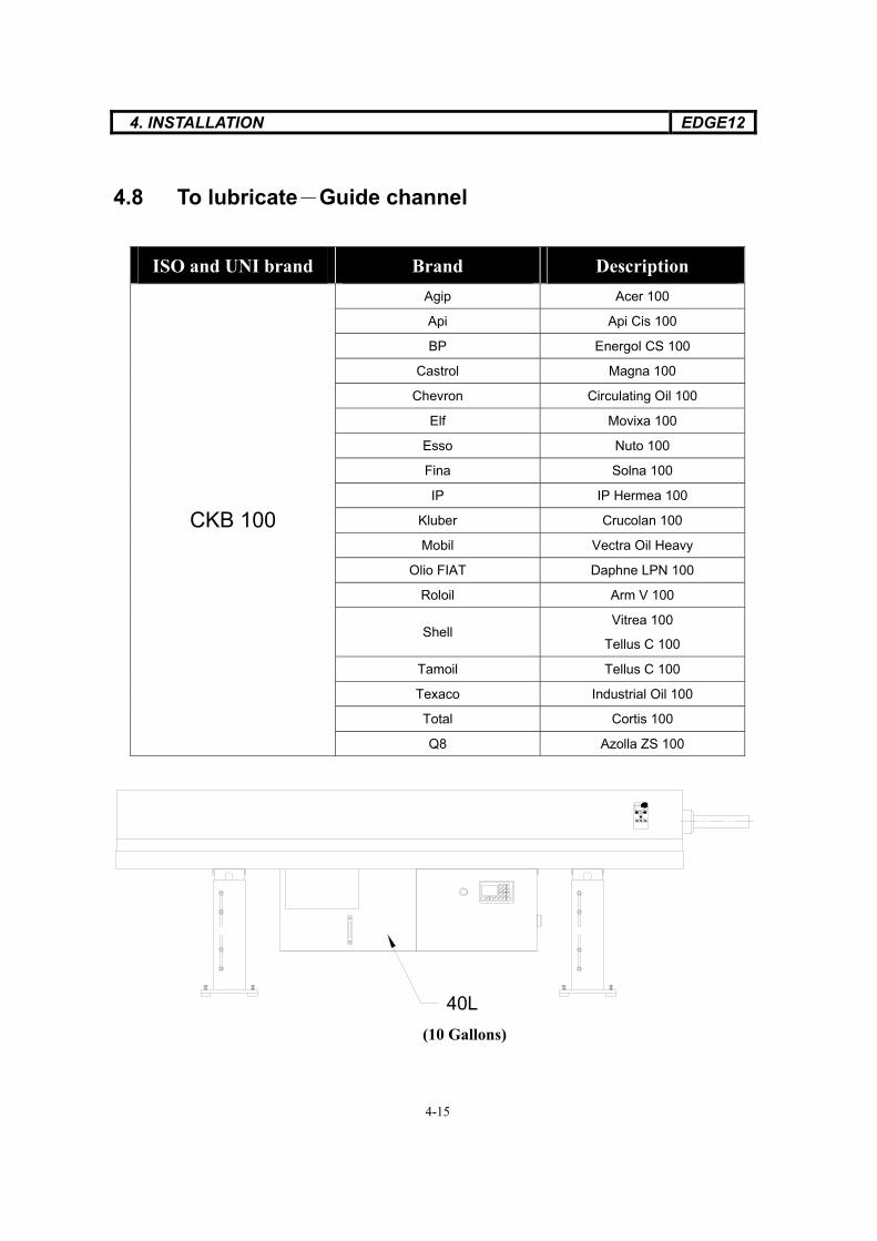
4.8 To lubricate Guide channel
ISO and UNI brand Brand Description Agip Acer 100
Api Api Cis 100
BP Energol CS 100
Castrol Magna 100
Chevron Circulating Oil 100
Elf Movixa 100
Esso Nuto 100
Fina Solna 100
IP IP Hermea 100
Kluber Crucolan 100
Mobil Vectra Oil Heavy
Olio FIAT Daphne LPN 100
Roloil Arm V 100
Shell Vitrea 100
Tellus C 100
Tamoil Tellus C 100
Texaco Industrial Oil 100
Total Cortis 100
CKB 100
Q8 Azolla ZS 100
40L
(10 Gallons)
5. ADJUSTMENT AND SETTING MM320
5-1
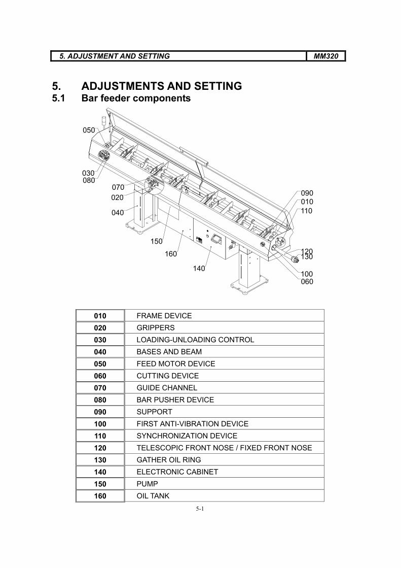
5. ADJUSTMENTS AND SETTING 5.1 Bar feeder components
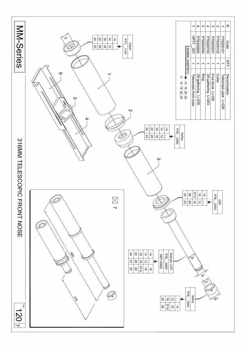
010 FRAME DEVICE 020 GRIPPERS 030 LOADING-UNLOADING CONTROL 040 BASES AND BEAM 050 FEED MOTOR DEVICE 060 CUTTING DEVICE 070 GUIDE CHANNEL 080 BAR PUSHER DEVICE 090 SUPPORT 100 FIRST ANTI-VIBRATION DEVICE 110 SYNCHRONIZATION DEVICE 120 TELESCOPIC FRONT NOSE / FIXED FRONT NOSE 130 GATHER OIL RING 140 ELECTRONIC CABINET 150 PUMP 160 OIL TANK
150
040
140
160
050
070020
080030
110
130120
100060
090010

5. ADJUSTMENTS AND SETTING MM-320
5-2
21
5.2 Adjustment of the loading device
5.2.1 Loosen the locking lever for the support plate 1 and lift the plate to the highest
position.
5.2.2 Place one of the bar to be machined on the magazine.
5.2.3 Rotate the knob 2 to adjust the bar stop so that only the first bar on the magazine
is lifted into the guide channel.
5.2.4 Loosen the lever 1 and slide the support plate down to 1mm over the bar to be
machined. Tighten the lever 1 .
5.2.5 Repeat above steps when changing bar diameters.

5. ADJUSTMENT AND SETTING MM320
5-3
A
5.3 Installation and adjustment – moveable anti-vibration
device (MAVD) and 1st anti-vibration device
5.3.1 Load a bar using the bar feeder into
the lathe and close lathe collet.
5.3.2 Press the Pre-Auto button , both
Anti-vibration devices will close.
5.3.3 Back screw (A) off counterclockwise
until no tention is felt on the screw
5.3.4 Press the Manual button , then
the Pre-Auto Button , this will
make sure rollers are closed onto bar.
5.3.5 Rotate screw (A) clockwise until
tention is felt, continue to rotate screw
clockwise for ¼ turn.
5.3.6 Tighten jam nut.
5.3.7 Press the Manual Button

5. ADJUSTMENTS AND SETTING MM-320
5-4
1
2
5.4 Feeding Chain
5.4.1 Loosen Locking screw for the tensioner.
5.4.2 Rotate knob 2 clockwise to tighten the belt for suitable tension.
5.4.3 Tighten the locking screw 1 .

6. OPERATION AND DESCRIPTION MM-320
6-1
6. OPERATIONS AND DESCRIPTION
6.1 Material preparation
Caution & prevention
Please don’t put the material out of standard.
List1 – The max length of material
The flatness of material must be within 0.5mm/M
Type Mod Min length mm (ft) Max length mm (ft)
21 914 (3) 2100 (6.8)
37 914 (3) 3800 (12.5) C-320
44 914 (3) 4400 (14.4)

6. OPERATION AND DESCRIPTION MM-320
6-2
6.2 Operator interface description
6.2.1 Function
CB
F1Shift F3F2 0
D
9
6
3
F
87
5
2
4
1
E
1 8
765432
A
NO. Function 1 LCD Display area 2 Shift 3 Function 4 ESC 5 Number 6 Enter 7 Run light 8 Power light

6. OPERATION AND DESCRIPTION MM-320
6-3
6.2.2 Shift screen
Press the key according to the indication on the display.
1 F1 Page up
2 F2 Page down
3 F3 Back to the main menu
6.2.3 Value change
1 Depress numbers as you require from 0~9.
2 Press enter F9
again, the value is changed. If you want to give up the
value, press .
6.2.4 Usage of key from F1~F9
1 Select F1~F3, press these three keys directly.
2 Select F4-F9, press and hold Shift key, and then select F4-F9.

6. OPERATION AND DESCRIPTION MM-320
6-4
6.2.5 The function and operation of keys
NO. Code Function NO. Code Function 1. PB2 Emergency STOP 13. LDS3 Clamping on light 2. DS6 Pre-automatic mode 14. DS4 Channel open/close 3. LDS6 Pre-automatic mode light 15. LDS4 Channel close light 4. DS10 Grippers clamping/unclamping 16. L2 Alarm light
5. DS1Manual advance (Right) Manual return (Left)
17. L1 Bar end
6. LDS1 Zero point light (Left) 18. L5 Bar change light 7. L3 Cycle start light 19. DS5 Automatic mode 8. L4 Chuck open light 20. LDS5 Automatic mode light 9. L6 Torque stop light 21. DS9 Manual loading
10 DS7 Manual mode 22. DS2Manual return (Right) Manual advance (Left)
11. LDS7 Manual mode light 23. LDS2 Zero point light (Right) 12. DS3 Manual clamping on/off
1.
2.
4.
5.
10.
12.
14.
19.
21.
22.
3.
6.15.
13.
11.20.
23.
18.
17.
16. 7.
8.
9.

6. OPERATION AND DESCRIPTION MM-320
6-5
6.2.6 The special operation
1. Rezero bar feeder
Open lathe collet
Make sure pusher is in channel and forward of zero switch
Press and hold pre-auto for 8 seconds until pusher starts to move
Release pre-auto , pusher will move to zero switch and stop
2. Advance / retreat at low-speed
When the lathe is on the left, the direction of and are reversed
1 Advance at low-speed press and .
2 Retreat at low-speed press and .
3. Automatic loading of bar
Open lathe collet
Jog pusher until zero position light is on
Press to move pusher back and turn light on
Press for channel to open and pusher to rise and turn light on
Press pre-auto until light is on, then auto until light is on
Magazine will load bar into channel and bar change will start.
Once bar is in lathe collet and at facing position the barfeed will time out after
20 sec. with an alarm unless the lathe collet is closed or the manual button
on the bar feeder is pressed.

6. OPERATION AND DESCRIPTION MM-320
6-6
4. Independent manual movement
Press key until, and flash on and off.
Then press
: Manual moveable anti-vibration device
: Manual 1st anti-vibration device
: Manual 2nd anti-vibration device (channel must be open first)
: Manual 3rd anti vibration device (channel must be open first)
: Manual 4th anti vibration device (channel must be open first)
: Manual synchronization device
Each device will turn on then off or open the close

6. OPERATION AND DESCRIPTION MM-320
6-7
6.3 Solenoid valve diagram 6.3.1 Air pressure diagram

6. OPERATION AND DESCRIPTION MM-320
6-8
6.3.2HP Series See also list Drawn 2006/05/04 Checked 2006/05/04Item designation Part NO. Description and function Suppliers reference Supplier

6. OPERATION AND DESCRIPTION MM-320
6-9
6.4 Parameter list and description
Mark Content Description Actual Value Default valueF1 User parameter
Part length + cutoff tool width 100 mm
Collet open pusher speed 20%
Collet open pusher torque 20%
Collet closed pusher speed 80%
Collet closed pusher torque 6%
Manual pusher speed 30%
Manual pusher torque 30%
Movable anti-vibration opening position 2900 mm
First feeding speed 20%
Oil pump shutoff position 0 mm
Long feed safety max. distance 5 mm
Short feed safety min. distance 0 mm
0 mm Sync device disengagement position Feeding slowdown position 0 mm
Installer use only as belowF2 Fixed parameter
Facing position 1435 mm
Max. pusher forward travel 3920 mm
First anti-vibration opening position 2550 mm
Second anti-vibration opening position 3200 mm
Third anti-vibration opening position 2200 mm
Fourth anti-vibration opening position 1350 mm
First feed max. travel 1438 mm
Cycle start delay after bar change .5 sec.
Bar change return delay 0 sec.
Pushing after collet close .2 sec.
Close collet timeout 0 sec.
Open collet timeout 0 sec.
Enterpassword
258
Bar change speed 90%

6. OPERATION AND DESCRIPTION MM-320
6-10
Technicians use only
F3 System function
F4: Movable anti-vibration On
F5: Language select English
PLC
Enterpassword
258F6: Program version
HMI
Enter next page
F4: Balance speed Off
F5: Balance torque Off
F4
F4: Demo mode On /Off Off
F5: LOGO shift EDGE
F6: CNC/CAM shift CNC
Enter next page
F4: Sliding / Fixed headstock Sliding
F5: Interface signal test
F6: Facing to position / stop Position
Enter next page
F4: Extraction / Ejection Extraction
Modify value of program while change work piece
Depend on situation
Setting up by technician

6. OPERATION AND DESCRIPTION MM-320
6-11
6.4.1 Description of settings and parameters of machine
F1 Turning parameter Setting unit Permit setting area Suggested setup
Monitor status
Description Monitor present bar being machined at any time when in auto.
Watch item 1. Pusher position – Position of pusher from bar feeder zero.
2. Material remaining – amount of material left on bar being machined.
3. Parts remaining – amount of parts left on bar being machined.
Setting unit Permit setting area Suggested setup Part length + cutoff tool width mm 0~999 New part length
Description Reset this parameter each time part length changes.
Setting method Part length + cutoff tool width = Total part machining length
Note Note In sliding headstock mode, long feed safety will automatically be set to 5mm each time this value is changed.
Setting unit Permit setting area Suggested setup Collet open pusher speed % 0~50 20%
Description Sets the pusher forward speed in automatic with lathe collet open.
Setting method : According to material size in relation with the collet open pusher torque.
Note Adjust in small increments to avoid bending of material, breakage of cutoff tool, or hitting material stop excessively hard.
Setting unit Permit setting area Suggested setup Collet open pusher torque % 0~99 20%
Description Sets the pusher forward torque in automatic with lathe collet open.
Setting method : According to material size and in relation with collet open pusher speed.
Note Adjust in small increments to avoid bending of material, breakage of cutoff tool, or hitting material stop excessively hard.

6. OPERATION AND DESCRIPTION MM-320
6-12
Setting unit Permit setting area Suggested setup Collet closed pusher speed % 0~99 80%
Description Sets the pusher forward speed in automatic with lathe collet closed.
Setting method : According to material size and in relation with the torque of chuck close. Note Adjust in small increments to avoid bending of material.
Setting unit Permit setting area Suggested setup Collet closed pusher torque % 0~99 6%
Description To set the feeding torque when CNC is chuck close in machining automatically.
Setting method : According to material size and in relation with the speed of chuck close.
Note Adjust in small increments to avoid bending of material. Setting unit Permit setting area Suggested setup
Manual pusher speed % 0~50 30%
Description Sets the pusher forward speed when bar feeder is in manual. Setting method Enter the speed needed to push bar.
Setting unit Permit setting area Suggested setup Manual pusher torque
% 0~100 30% Description Sets the pusher forward torque when bar feeder is in manual.Setting method Enter the torque needed to push bar.
Setting unit Permit setting area Suggested setup Movable anti – vibration opening
positionmm 0~4000
Short 25 ~ 50 mm from Movable anti-vibration
Description The movable anti–vibration opening position allows the pusher to proceed past the movable anti–vibration decive in automatic mode. Value must be changed acordingly each time lathe Z axis rechuck position is changed.
Setting method Move lathe Z axis to part rechuck position. Jog pusher forward until pusher collet is just visible inside moveable anti-vibration device. Subtract 25 ~ 50 mm from pusher position and input value.
Note If unable to set this setting each time, move lathe Z axis to –Z over travel position away from guide bushing. Jog pusher forward until pusher collet is just visible inside moveable anti-vibration device. Subtract 25 ~ 50 mm from pusher position and input value. Value will not have to be changed again.

6. OPERATION AND DESCRIPTION MM-320
6-13
Setting unit Permit setting area Suggested setup First feeding speed
% 0~50 20% Description The first feeding speed is set for when material is being loaded into
lathe.Setting method Set value according to material diameter for first feeding speed. Note Set speed so material loads smoothly and does not drift off pusher
because of inertia.
Setting unit Permit setting area Suggested setup Oil pump shutoff position mm 0~4000 3000mm
Description Position of pusher when oil shuts off when bar feeder is in automatic.
Setting method Move lathe Z axis to –Z over travel position, move barfeed pusher so pusher collet can be seen inside moveable anti-vibration device. Set value matching pusher position.
Note Value is initially set to zero upon arrival at customer, please set during installation. Oil pump will come on once barfeed is in automatic.Setting unit Permit setting area Suggested setup
Long feed safety max. distance mm 0~999
Finish product length + 5~30mm
Description When pusher moves further than value set in automatic with lathe collet open, barfeed will alarm with long feed error.
Setting method Fixed headstock : Finish product length + permitable feeding error Sliding headstock : Permitable feeding error
Ex Fixed headstock : 15mm is automatically added to part length + cutoff tool width parameter and set automatically Sliding headstock : 5mm is set automatically
Refer to figure 1

6. OPERATION AND DESCRIPTION MM-320
6-14
Setting unit Permit setting area Suggested setup Short feed safety
max. distance mm 0~999 Finish product length -
5~10mmDescription When pusher moves less than value set in automatic when lathe
collet closes, barfeed will alarm with short feed error. Setting method Fixed headstock : Finish product length - permitable feeding error
Sliding headstock :set to zero Ex Fixed headstock : 15mm is automatically subtracted to part length + cutoff tool width parameter and set automatically Sliding headstock : 0mm is set automatically
Fixed headstock : Finish product length 50mm - error value 5mm = Short feed safety 45mm
Refer to figure 1
Feeding direction Workpiece length
Short feed safety
Long feed safety
Abnormal area
Permit error value
Material
(Figure 1)Finish product

6. OPERATION AND DESCRIPTION MM-320
6-15
Setting unit Permit setting area Suggested setup Sliding headstockSync. device disengagementposition.
Fixed headstockFeeding slowdown position.
mm 0~999
Sync. device disengagementposition The finish product length – 10mm
Description The sychronization device will disengage prior to lathe collet opening so when lathe headstock moves to rechuck position, no delay is needed between lathe collet open and Z axis movement. (It is restricted to Sliding headstock mode only).
Feeding slowdown position Allow slowdown of pusher during feedout of material to prevent material from hitting stock stop excessively hard. (It is restricted to Fixed headstock mode only
Setting methodSliding headstock Synchronization device opening position
The finish product length required to release range = Synchronization device opening position
(Normally set to zero, synchronization device will disengage at lathe collet open and engage at lathe collet close)
Fixed headstock Feeding slowdown position Depend on the finish product length
Reference figure 4Synchronization device opening positionThe finish product length 50mm – 10mm = 40mm
Feeding slowdown position The finish product length 50mm – 10mm = Feeding slowdown position
0mm 40mm 50mm
(Figure 4)
Opening position
Finish product length
Sliding headstock
Finish product length
0mm
Fixed headstock
Feed slowdown position
40mm 50mm
Fixed headstock
Sliding headstock
Finish product
Finish product length
Feed slowdown position

6. OPERATION AND DESCRIPTION MM-320
6-16
F2 Fixed parameter Setting unit Permit setting area Suggested setup
Facing positionmm 0~4000 Depend on actual length
Description Position of new bar loaded automatically by barfeed. All bars regardless of length being loading to facing position when barfeed is in automatic.
Setting method : Sliding headstock: Measure from facing flag (LS4) to face of guide bushing, subtract 50mm (2”), set value (In lathe bar change
program set Z axis stroke for material extraction and introduction into guide bushing at 75mm (3”))
Fixed headstock : Measure from facing flag (LS4) to face of collet, note value, add additional amount for lathe to cutoff, set total value.
Setting unit Permit setting area Suggested setup Maximum pusher forward travel mm 0~4000 Depend on actual length
Description Maximum distance bar can feed into lathe.Setting method Sliding headstock : Move lathe Z axis to over travel position toward guide bushing. In manual mode move pusher forward until pusher collet stops moving against lathe collet, subtract 2mm from current pusher position and set value. Fixed headstock : In manual mode move pusher forward until pusher collet stops moving against lathe collet, subtract 2mm from current pusher position and set value.
Bar feeder side
(Reference figure 2) Chuck
Facing detection LS4
(Reference figure 3) Chuck
2mm
Pusher

6. OPERATION AND DESCRIPTION MM-320
6-17
Setting unit Permit setting area Suggested setup Firstanti–vibration
opening position mm 0~2650 2550mm
Description The first anti–vibration device will open just prior to the pusher collet reaching the first anti–vibration device in automatic.
Setting method In manual jog pusher forward until pusher collet is 30~50mm away from first anti–vibration device.
Set the value using the pusher position current value. Note First anti–vibration device should be open before the pusher collet
arrives to avoid material separating from the pusher collet.
Setting unit Permit setting area Suggested setup Secondanti–vibration
opening position mm 3000~3375 3200mm
Description The second anti–vibration device will open just prior to the pusher flag reaching the second anti-vibration device.Setting method In manual jog pusher forward until pusher flag is 80-120mm away from second anti–vibration device. Set the value using the pusher position current value. Note The Second anti–vibration device should be open before the pusher
flag arrives to avoid material separating from the pusher collet.
Setting unit Permit setting area Suggested setup Thirdanti–vibration
opening position mm 2000~2375 2200mm
Description The third anti–vibration device will open just prior to the pusher
flag reaching the third anti-vibration device.
Setting method In manual jog pusher forward until pusher flag is 80-120mm away from third anti–vibration device.
Set the value using the pusher position current value.
Note The third anti–vibration device should be open before the pusher
flag arrives to avoid material separating from the pusher collet.

6. OPERATION AND DESCRIPTION MM-320
6-18
Setting unit Permit setting area Suggested setup Forthanti–vibration
opening position mm 1200~1475 1350mm
Description The fourth anti–vibration device will open just prior to the pusher flag reaching the forth anti-vibration device. Setting method In manual jog pusher forward until pusher flag is 80-120mm away from fourth anti–vibration device.
Set the value using the pusher position current value. Note The third anti–vibration device should be open before the pusher
flag arrives to avoid material separating from the pusher collet. Setting unit Permit setting area Suggested setup First feed max.
travel mm 1400~1470 1438mm
Description Position of new bar during first feed to allow pusher collet to enter
material.
Setting method In manual mode open channel, move the first feeding pusher
forward to the main pusher insert depth of limitation.
Set the current value of pusher postion.
Note Distance shall be set to avoid material collision with pusher collet at
channel close. Distance should allow for pusher introduction onto
material until stop in pusher is reached only.
Setting unit Permit setting area Suggested setup Cycle start after bar change sec 0~10.0 0.5sec
Description Delay after new bar reaches facing position before cycle start signal is sent from barfeed to lathe.
Setting method Enter value required for delay. Note The longer the set time the longer bar change will take
100~150mm
Reference figure 5 )(Reference figure 5)Inserted
depth
First feeding distanceFirst feeding slowdown distance
6. OPERATION AND DESCRIPTION MM-320
6-19
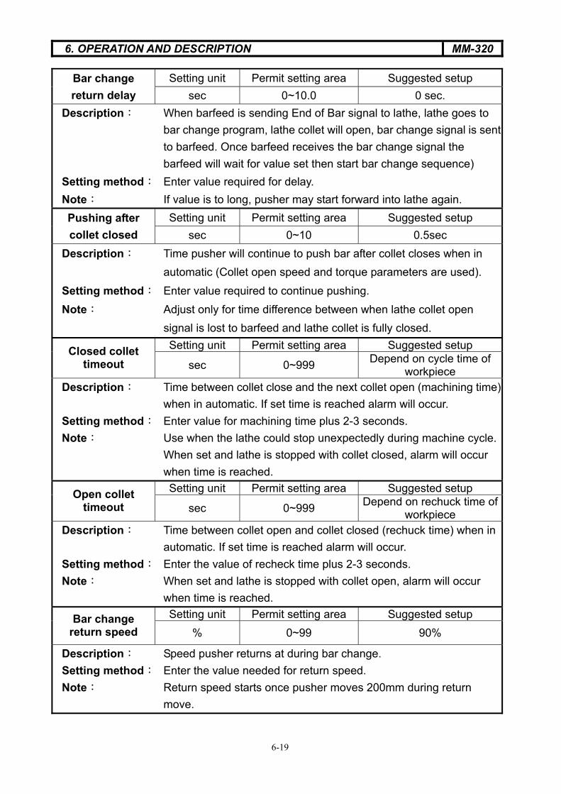
Setting unit Permit setting area Suggested setup Bar change return delay sec 0~10.0 0 sec.
Description When barfeed is sending End of Bar signal to lathe, lathe goes to bar change program, lathe collet will open, bar change signal is sent to barfeed. Once barfeed receives the bar change signal the barfeed will wait for value set then start bar change sequence)
Setting method Enter value required for delay.Note If value is to long, pusher may start forward into lathe again.
Setting unit Permit setting area Suggested setup Pushing after collet closed sec 0~10 0.5sec
Description Time pusher will continue to push bar after collet closes when in automatic (Collet open speed and torque parameters are used).
Setting method Enter value required to continue pushing. Note Adjust only for time difference between when lathe collet open signal is lost to barfeed and lathe collet is fully closed.
Setting unit Permit setting area Suggested setup Closed collet timeout sec 0~999 Depend on cycle time of
workpiece Description Time between collet close and the next collet open (machining time)
when in automatic. If set time is reached alarm will occur. Setting method Enter value for machining time plus 2-3 seconds. Note Use when the lathe could stop unexpectedly during machine cycle.
When set and lathe is stopped with collet closed, alarm will occur when time is reached. Setting unit Permit setting area Suggested setup Open collet
timeout sec 0~999 Depend on rechuck time of workpiece
Description Time between collet open and collet closed (rechuck time) when in automatic. If set time is reached alarm will occur.
Setting method Enter the value of recheck time plus 2-3 seconds. Note When set and lathe is stopped with collet open, alarm will occur
when time is reached. Setting unit Permit setting area Suggested setup Bar change
return speed % 0~99 90%
Description Speed pusher returns at during bar change. Setting method Enter the value needed for return speed. Note Return speed starts once pusher moves 200mm during return
move.

6. OPERATION AND DESCRIPTION MM-320
6-20
F3 System function – enter pass word 258 Setting unit Permit setting area Default F4 : Movable
anti-vibration device On / Off On / Off Off Description Sets the useable modes of the moveable anti-vibration
device.On : The movable anti -vibration will open or close along with the
chuck of the lathe after the pusher collet reaches the movable anti-vibration opening parameter plus 150mm.
Off : The movable anti -vibration will open when the pusher collet reaches the movable anti-vibration device opening parameter and stay open until after the next bar change. Setting unit Permit setting area Default F5 Language select
English English English
Description This bar feeder provides multi languages to select according to
different requirement.
At present provide
F1 English
Program # PLCF6 Program versionHMI
Enter next pageSetting unit Permit setting area Suggested setup F4 Balance
Speed On / Off On / Off Off
Description Balance the speed of the servo drive. Setting method Contact Edge Technologies for procedure for balancing of drive.
Setting unit Permit setting area Suggested setup F5 Balance torque On / Off On / Off Off
Description Balance the torque of the servo drive. Setting method Contact Edge Technologies for procedure for balancing of drive.

6. OPERATION AND DESCRIPTION MM-320
6-21
F4 Particular Program modify– enter pass word
Setting unit Permit setting area Note F4 Demo Mode
On / Off On / Off Off
Description Sets the barfeed to demo mode. (Set collet open and bar change to on)
Setting unit Permit setting area Note F5 LOGOEDGE EDGE EDGE
Description Sets the logo on the operators panel.
Setting unit Permit setting area Note F6 CNC/CAM mode
Switch function
Description Sets the style of lathe attached to barfeed. CNC or CAM.
Enter next pageSetting unit Permit setting area Note F4:Sliding / Fixed
headstock Sliding / Fixed Sliding / Fixed Sliding
Description Sets the type of lathe, sliding headstock or fixed headstock.
Setting unit Permit setting area Note F5 Interface signal test Test signals of bar
feeder and lathe Description Sets output signals to barfeed once interfaced to lathe. Test item
F1 Bar end F4 Start itself F2 Alarm F5 Start F3 Inching F6 Auto
Setting unit Permit setting area Note F6 Facing to position / stop Position / Stop Position / Stop Position
Description Set the new material position.
To position The new bar will be loaded to set measured position in the lathe then send
cycle start signal.
Facing close The new bar will be loaded to set measured position in the lathe, pause,
then feed again until pusher hits stock stop in lathe then send cycle start
signal.

6. OPERATION AND DESCRIPTION MM-320
6-22
Enter next pageSetting unit Permit setting area Note F4: Extraction /
Ejection Extraction
Description Select removal method of remnant
Extraction During bar change the barfeed will pull the remnant back with the pusher,
the grippers will check the remnant was pulled out of the lathe spindle and
drop the remnant in the catch pan.
Ejection during bar change the barfeed will leave the remnant in the lathe spindle. The
barfeed pusher will return and load a new bar. (The grippers will not check for
the presents of the remnant). During loading of the new bar into the spindle
the bar will push the previous remnant through the lathe collet and into the
bottom of the lathe.
Can be used on fixed headstock lathes at any time with a front ejection collet
(Should only be used on sliding headstock lathes when in fixed headstock mode)
Setting unit Permit setting area Note

6. OPERATION AND DESCRIPTION MM-320
6-23
6.5 Alarm message list
NO. ERROR CAUSE CURE
Alarm01Pusher cannot return to home during bar change
Check for pusher obstruction. Adjust home return speed.
Alarm02 Long feed safety Pusher moved further than set value with collet open, check parameter, check lathe collet.
Alarm03 Short feed safety Pusher moved less than set value when collet closed, check parameter, check lathe collet.
Alarm04Collet closed during bar
change
Then collet open signal was lost to barfeed during automatic bar change. Check lathe program, check wiring to and in barfeed.
Alarm05Remnant not extracted
from pusher collet
Check tension of collet on material. Check gripper tension. Check gripper switch
Alarm06 Lathe Alarm Lathe alarm was sent to barfeed, check E-stop on lathe
Alarm07Remnant detected after
extraction
Remnant did not drop in barfeed, check pusher collet tension, check gripper switch
Alarm08 Pusher up time out Channel could not open, check switch LS3 , check air pressure.
Alarm09 Pusher down time out Channel could not close, check switch LS4 , check air pressure.
Alarm10Facing flag proximity switch not present
Check switch SR2
Alarm11 First feeding timeout Check parameter of first feeding speed, check for material obstruction.
Alarm12 No new bar present Material did not load into channel, gripper switch did not detect bar, gripper switch not working.
Alarm13 First feeing return time outPusher did not return in time during firstfeeding return, check for obstruction,
check air pressure.

6. OPERATION AND DESCRIPTION MM-320
6-24
Alarm14Pusher collet introduction
onto collet timeout
Check collet to small for material O.D., material O.D. to large, No chamfer on material, Check switch SR1, check air pressure.
Alarm15 Material is too short. Material length is too short to load automatically
Alarm16Barfeed cannot reach
facing position Check material for burr or chamfer, check the value of facing position.
Alarm17Lathe failed to start after
cycle start Check lathe wiring for receiving of cycle start signal
Alarm18LS3 and LS4 on at the
same time Check position of LS3 and LS4
Alarm19LS2 and SR1 on at the
same time . Check position of LS2 and SR1
Alarm20 Collet close timeout Lathe collet close longer that set parameter timer
Alarm21 Servo alarm Check the alarm No. on LCD display of servo. Reset with power down of barfeed by 3 phase switch for 5 sec.
Alarm22Barfeed not in auto when
lathe is running
After lathe collet opens and close 3 times with the barfeed in manual alarm will occur.
Alarm23 Oil pump overloads trippedReset overloads, check for oil in tank, check electrical connections.
Alarm24 Program has mistake Program downloaded incorrectly, download again.
Alarm25Hood not closed during bar
change.Hood must be closed during bar change, check hood safety switch.
Alarm26 Collet open timeout Lathe collet open longer that set parameter timer
Alarm27Synchronization device
disengaged at pusher zero
Pusher within 20mm of zero with sync engaged (lathe collet closed). Move pusher past 20mm and close collet.
Alarm28Cannot jog pusher with
collet closed
Synchronization device engaged. Open lathe collet to jog barfeed pusher manually
Alarm29 Air pressure low Increase air pressure.

6. OPERATION AND DESCRIPTION MM-320
6-25
6.5.1 Description of Alarm 23:
O.L position of unit, please refer to page 5-2.
In normal operation, identification window is blue. The identification window will show
T up when overload is tripped. Check whether enough oil is in tank or if pump has
malfunctioned. If Ok, press the button “RESET” at the right up corner, the identification
window will return to blue.
O.L over current relay
identification window

6. OPERATION AND DESCRIPTION MM-320
6-26
6.5.2 Description of alarm 21:

6. OPERATION AND DESCRIPTION MM-320
6-27

6. OPERATION AND DESCRIPTION MM-320
6-28

6. OPERATION AND DESCRIPTION MM-320
6-29

6. OPERATION AND DESCRIPTION MM-320
6-30

6. OPERATION AND DESCRIPTION MM-320
6-31

7. MAINTENANCE MM320
7-1
7. MAINTENANCE
7.1 General maintenance
�� Hazard-warning Before doing bar feeder maintenance, turn off 3 phase power.
For consistent operation of the bar feeder, please do maintenance checks regularly.
The area around the barfeed should be kept clean to avoid safety issues.
Using petroleum or other solvents may damage plastic components.

7. MAINTENANCE MM320
7-2
7.2 Regular maintenance
List 1. Regular maintenance
Frequency Hours Regular Period Component Action
200 1250 2500 Collet Check wear
Guide channel Check wear and
clean Lubrication
Feeding chain Tension Air cleaner Check
7.2.1 Check the pusher collet and revolving tip
Check that revolving tip (A) rotates smoothly Check that pusher collet (B) has the correct tension.
7.2.2 Check the air regulator
Check the bottle (B) for water.
Press button (C) to exhaust water out of bottle.
cB
A
B

8. Troubleshooting MM320
8-1
8. Cause and breakdown and troubleshooting
8.1 Troubleshooting issues ITEM Cause Solution
No power Check the power source Unable to start the bar Feeder In E-stop Clear E-stop of barfeed and
lathe. The barfeed is in automatic but the barfeed will not feed
Feed stop signal is sent from lathe, no collet open signal is sent from lathe
Check interface.
Air alarm, cylinder will not actuate
Not enough air pressure Increase air pressure
8.2 Troubleshooting frame Situation Cause Solution
Material is unable to load on the magazine
Guide plates too low Adjust the position of the plates
8.3 Troubleshooting pusher collet Situation Cause Solution
The adjustment of the clamp device is not correct
Re-adjust
The diameter of collet and material are different.
Change collet.
The end of the material is too rough.
Chamfer before feeding material
Material is unable to be inserted into the collet.
The air pressure is insufficient.
Check the pressure
8.4 Troubleshooting feeding mechanism Situation Cause Solution
Material can't feed into the spindle smoothly
The center of the bar feeder and the lathe isn't correct
Realign barfeed
Material can't feed into the collet of the lathe smoothly
The front of the material is too rough.
Chamfer before feeding material