model am14 & am14c dishwashers - parts...
TRANSCRIPT
MODEL AM14 & AM14C DISHWASHERS
MODELS
AM14 ML-32614AM14C ML-32615
701 S. RIDGE AVENUE
TROY, OHIO 45374-0001
937 332-3000
www.hobartcorp.com FORM 34123 Rev. C (Oct. 2000)
– 2 –
POST IN A PROMINENT LOCATION THE INSTRUCTIONS TO BE FOLLOWED IN THEEVENT THE SMELL OF GAS IS DETECTED. THIS INFORMATION CAN BE OBTAINEDFROM THE LOCAL GAS SUPPLIER.
IMPORTANT
IN THE EVENT A GAS ODOR IS DETECTED, SHUTDOWN UNIT(S) AT MAIN SHUTOFF VALVE ANDCONTACT THE LOCAL GAS COMPANY OR GASSUPPLIER FOR SERVICE.
FOR YOUR SAFETY
DO NOT STORE OR USE GASOLINE OR OTHERFLAMMABLE VAPORS OR LIQUIDS IN THEVICINITY OF THIS OR ANY OTHER APPLIANCE.
© HOBART CORPORATION 1982, 1995
– 3 –
TABLE OF CONTENTS
GENERAL . . . . . . . . . . . . . . . . . . . . . . . . . . . . . . . . . . . . . . . . . . . . . . . . . . . . . . . . . . . . . . . . 4
INSTALLATION . . . . . . . . . . . . . . . . . . . . . . . . . . . . . . . . . . . . . . . . . . . . . . . . . . . . . . . . . . . . 5
UNPACKING . . . . . . . . . . . . . . . . . . . . . . . . . . . . . . . . . . . . . . . . . . . . . . . . . . . . . . . . . . 5INSTALLATION CODES . . . . . . . . . . . . . . . . . . . . . . . . . . . . . . . . . . . . . . . . . . . . . . . . . 5LOCATION . . . . . . . . . . . . . . . . . . . . . . . . . . . . . . . . . . . . . . . . . . . . . . . . . . . . . . . . . . . . 5WATER REQUIREMENTS . . . . . . . . . . . . . . . . . . . . . . . . . . . . . . . . . . . . . . . . . . . . . . . 6PLUMBING CONNECTIONS . . . . . . . . . . . . . . . . . . . . . . . . . . . . . . . . . . . . . . . . . . . . . 6
DRAIN CONNECTION. . . . . . . . . . . . . . . . . . . . . . . . . . . . . . . . . . . . . . . . . . . . . . . 6WATER CONNECTION . . . . . . . . . . . . . . . . . . . . . . . . . . . . . . . . . . . . . . . . . . . . . . . 6
Without Electric or Gas Booster Water Heater . . . . . . . . . . . . . . . . . . . . . . . . . 6With Electric Booster Water Heater . . . . . . . . . . . . . . . . . . . . . . . . . . . . . . . . . . 7
GAS TANK HEAT . . . . . . . . . . . . . . . . . . . . . . . . . . . . . . . . . . . . . . . . . . . . . . . . . . . 7VENTING REQUIREMENTS — WITH GAS TANK HEAT . . . . . . . . . . . . . . . . . . . 8RATE OF EXHAUST FLOW CALCULATIONS . . . . . . . . . . . . . . . . . . . . . . . . . . . . 9STEAM HEAT . . . . . . . . . . . . . . . . . . . . . . . . . . . . . . . . . . . . . . . . . . . . . . . . . . . . . 10
ELECTRICAL CONNECTIONS. . . . . . . . . . . . . . . . . . . . . . . . . . . . . . . . . . . . . . . . . . . 10DISHWASHER CONNECTION . . . . . . . . . . . . . . . . . . . . . . . . . . . . . . . . . . . . . . . . 10
Check Rotation (Three Phase Machines Only) . . . . . . . . . . . . . . . . . . . . . . . . 10ELECTRIC BOOSTER WATER HEATER CONNECTION . . . . . . . . . . . . . . . . . . 11OPTIONAL EQUIPMENT CONTROL CONNECTIONS . . . . . . . . . . . . . . . . . . . . 11
Detergent Dispenser . . . . . . . . . . . . . . . . . . . . . . . . . . . . . . . . . . . . . . . . . . . . . 11Rinse Aid Dispenser . . . . . . . . . . . . . . . . . . . . . . . . . . . . . . . . . . . . . . . . . . . . . 11Vent Fan Control . . . . . . . . . . . . . . . . . . . . . . . . . . . . . . . . . . . . . . . . . . . . . . . . 11Hobart Infrared Booster Gas Water Heater . . . . . . . . . . . . . . . . . . . . . . . . . . . 11
ELECTRICAL DATA . . . . . . . . . . . . . . . . . . . . . . . . . . . . . . . . . . . . . . . . . . . . . . . . 12
OPERATION . . . . . . . . . . . . . . . . . . . . . . . . . . . . . . . . . . . . . . . . . . . . . . . . . . . . . . . . . . . . . 13
PREPARATION . . . . . . . . . . . . . . . . . . . . . . . . . . . . . . . . . . . . . . . . . . . . . . . . . . . . . . . 13DISHWASHING . . . . . . . . . . . . . . . . . . . . . . . . . . . . . . . . . . . . . . . . . . . . . . . . . . . . . . . 14CLEANING . . . . . . . . . . . . . . . . . . . . . . . . . . . . . . . . . . . . . . . . . . . . . . . . . . . . . . . . . . . 15DOs AND DON’Ts FOR YOUR NEW HOBART WAREWASHER . . . . . . . . . . . . . . . 16
MAINTENANCE . . . . . . . . . . . . . . . . . . . . . . . . . . . . . . . . . . . . . . . . . . . . . . . . . . . . . . . . . . 17
WASH ARMS . . . . . . . . . . . . . . . . . . . . . . . . . . . . . . . . . . . . . . . . . . . . . . . . . . . . . . . . 17MOTOR(S) . . . . . . . . . . . . . . . . . . . . . . . . . . . . . . . . . . . . . . . . . . . . . . . . . . . . . . . . . . . 17GAS FLUE . . . . . . . . . . . . . . . . . . . . . . . . . . . . . . . . . . . . . . . . . . . . . . . . . . . . . . . . . . . 17
TROUBLESHOOTING . . . . . . . . . . . . . . . . . . . . . . . . . . . . . . . . . . . . . . . . . . . . . . . . . . . . . 17
MANUAL RESET BUTTON ON PUMP MOTORS . . . . . . . . . . . . . . . . . . . . . . . . . . . . 17SERVICE . . . . . . . . . . . . . . . . . . . . . . . . . . . . . . . . . . . . . . . . . . . . . . . . . . . . . . . . . . . . 20
– 4 –
Installation, Operation, and Care ofMODEL AM14 & AM14C DISHWASHERS
SAVE THESE INSTRUCTIONS
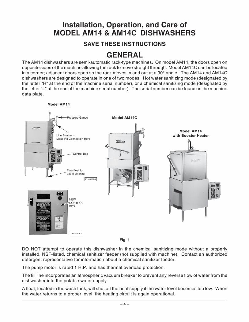
GENERALThe AM14 dishwashers are semi-automatic rack-type machines. On model AM14, the doors open onopposite sides of the machine allowing the rack to move straight through. Model AM14C can be locatedin a corner; adjacent doors open so the rack moves in and out at a 90° angle. The AM14 and AM14Cdishwashers are designed to operate in one of two modes: Hot water sanitizing mode (designated bythe letter "H" at the end of the machine serial number), or a chemical sanitizing mode (designated bythe letter "L" at the end of the machine serial number). The serial number can be found on the machinedata plate.
Model AM14
Model AM14C
Model AM14with Booster Heater
Fig. 1
DO NOT attempt to operate this dishwasher in the chemical sanitizing mode without a properlyinstalled, NSF-listed, chemical sanitizer feeder (not supplied with machine). Contact an authorizeddetergent representative for information about a chemical sanitizer feeder.
The pump motor is rated 1 H.P. and has thermal overload protection.
The fill line incorporates an atmospheric vacuum breaker to prevent any reverse flow of water from thedishwasher into the potable water supply.
A float, located in the wash tank, will shut off the heat supply if the water level becomes too low. Whenthe water returns to a proper level, the heating circuit is again operational.
PL-40827-1
Pressure Gauge
Line Strainer - Make Fill Connection Here
Control Box
Turn Feet toLevel Machine
PL-41176-1
NEWCONTROLBOX
– 5 –
Available as an optional accessory is a frame-mounted 10KW electric booster to maintain a minimumfinal rinse temperature of 180°F.
Also available as an optional accessory is the model IB57 Infrared Booster Gas Water Heater.
Also available are circuit breaker(s) and/or single point electrical connection options.
INSTALLATIONUNPACKING
Immediately after unpacking the dishwasher, check for possible shipping damage. If this machine isfound to be damaged, save the packaging material and contact the carrier within 15 days of delivery.
Prior to installation, test the electrical service to make sure it agrees with the specifications on themachine data plate (and booster data plate if applicable). The dishwasher data plate is located eitheron the front of the upper wash tank, viewable after the front panel is removed, or on the side of thecontrol box. A separate data plate for the electric booster is located on the back side of the booster(when equipped).
INSTALLATION CODES
Installation must be in accordance with state and local codes, or in the absence of local codes, withthe National Fuel Gas Code, ANSI Z223.1 (latest edition) if applicable, and the National Electrical CodeANSI/NFPA 70 (latest edition). In Canada, the installation standards are: CAN/CGA B149.1,CAN/CGA B149.2, and CSA C22.2 No.1 (latest editions).
LOCATION
Place the dishwasher in its operating location. Before finalizing the location, make sure thatconsideration has been given for the electrical conduit, water supply, drain connection, steam or gassupply and venting (if applicable), tabling (if needed), chemical feeder replenishment (if applicable),and adequate clearance for opening the doors. Allow adequate clearance for service.
The control box (Fig. 1) is mounted 45/8" below the dishtable when shipped from the factory. It can be changedto 125/8" or 31/8" below the dish table by removing thetwo mounting bolts and reinstalling them in the holesprovided.
The dishwasher must be level before any connectionsare made. Turn the threaded feet (Fig. 1) as requiredto level the machine and adjust to the desired height.
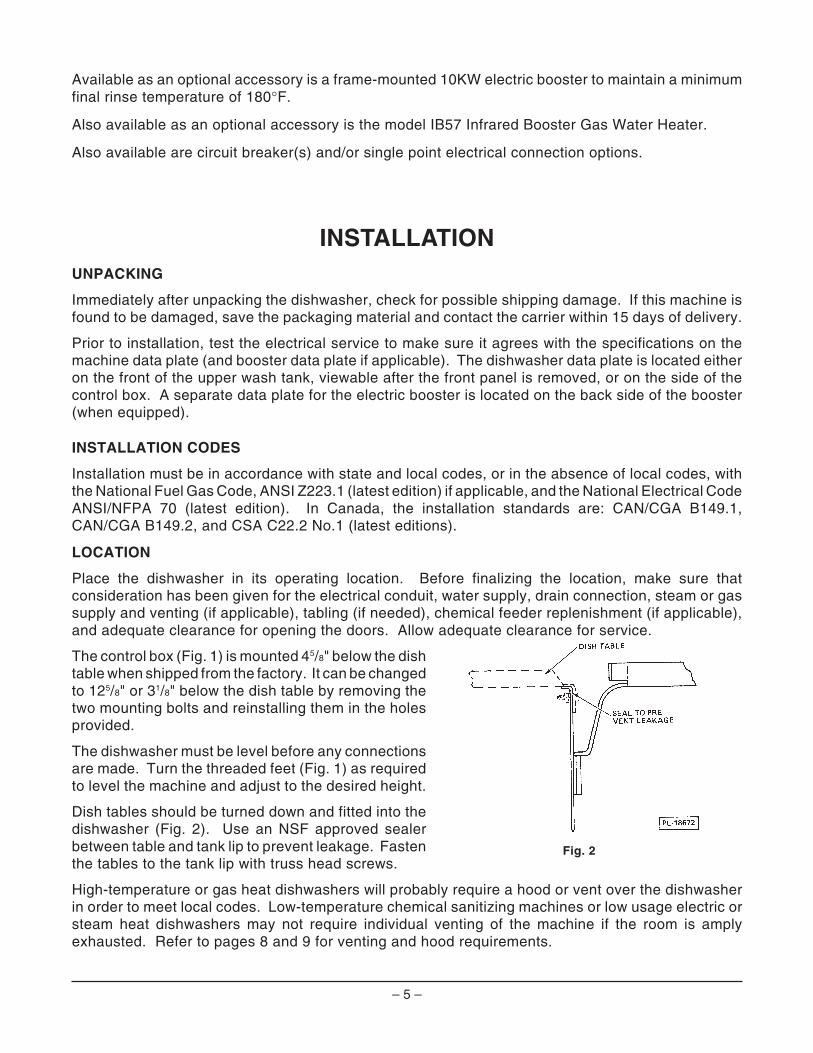
Dish tables should be turned down and fitted into thedishwasher (Fig. 2). Use an NSF approved sealerbetween table and tank lip to prevent leakage. Fastenthe tables to the tank lip with truss head screws.
High-temperature or gas heat dishwashers will probably require a hood or vent over the dishwasherin order to meet local codes. Low-temperature chemical sanitizing machines or low usage electric orsteam heat dishwashers may not require individual venting of the machine if the room is amplyexhausted. Refer to pages 8 and 9 for venting and hood requirements.
Fig. 2
– 6 –
WATER REQUIREMENTS
Proper water quality can improve ware washing performance by reducing spotting, lowering chemicalsupply costs, enhancing effectiveness of labor, and extending equipment life. Local water conditionsvary from one location to another. The recommended proper water treatment for effective and efficientuse of this equipment will also vary depending on the local water conditions. Ask your municipal watersupplier for details about local water specifics prior to installation.
Recommended water hardness is 4 – 6 grains of hardness per gallon. Chlorides must not exceed 50parts per million. Water hardness above 6 grains per gallon should be treated by a water conditioner(water softener or in-line treatment). Water hardness below 4 grains per gallon also requires a watertreatment to reduce potential corrosion. Water treatment has been shown to reduce costs associatedwith machine cleaning, reduce deliming of the dishwasher, reduce detergent usage, and reducecorrosion of metallic surfaces in the booster water heater and dishwasher.
Sediment, silica, chlorides, or other dissolved solids may lead to a recommendation for particulatefiltration or reverse osmosis treatment.
If an inspection of the dishwasher or booster heater reveals lime build-up after the equipment has beenin service, in-line water treatment should be considered, and, if recommended, should be installed andused as directed. Contact your Hobart Service office for specific recommendations.
PLUMBING CONNECTIONS
WARNING: PLUMBING CONNECTIONS MUST COMPLY WITH APPLICABLE SANITARY, SAFETY,AND PLUMBING CODES.
DRAIN CONNECTION
The drain connection is made using 2" pipe.
If a right hand drain is desired, it can be changed from the standard left-hand by removing the pipe plugfrom the drain valve and reinstalling it in the opposite end of the drain valve.
If a grease trap is required by code, it should have a minimum flow capacity of 42 gallons per minute.
WATER CONNECTION
A suitable water hammer arrestor should be installed in the water line just ahead of the dishwasher.
Without Electric or Gas Booster Water Heater
The water supply line is connected to the line strainer (Fig. 1) with 3/4" pipe.
Minimum water temperatures are listed below:
Sanitizing Mode Wash RinseHot Water 150°F (66°C) 180°F (82°C)Chemical (Normal Duty) 120°F (49°C)* 120°F (49°C)*Chemical (Light Duty) 130°F (54°C)* 120°F (49°C)*
* Temperatures shown are minimum; recommended temperature is 140°F (60°C).
Proper dishwasher operation requires a flowing pressure of 20 ± 5 psig at the dishwasher. If theflowing pressure exceeds 25 psig, a pressure reducing valve (not supplied) must be installed in thewater supply line. CAUTION: The water pressure regulator must have a relief by-pass. Failureto use the proper type of pressure regulator may result in damage to the unit.
A pressure gauge (Fig. 1) is provided for verification of proper water pressure. Present modelsmonitor the water pressure when the solenoid valve is open and water is flowing. On earlier modelswhere the pressure gauge was connected into a petcock, the petcock MUST always remain closedexcept when making an instantaneous check of flowing pressure.
– 7 –
With Electric Booster Water Heater
The water supply line is connected to the booster (Fig. 6) with 3/4" pipe.
The water supply should have a minimum temperature of 120°F – 140°F, and a flowing pressure of 15 –25 psig at the pressure gauge tee beside the solenoid valve. If the flowing pressure exceeds 25 psig,a pressure reducing valve (not supplied) must be installed in the water supply line. CAUTION: Thewater pressure regulator must have a relief by-pass. Failure to use the proper type of pressureregulator may result in damage to the unit.
Incoming water temperature below 120°F may require the wash cycle time to be extended from 40 to60 seconds. To have the cycle time adjusted, contact your local authorized Hobart Service Office.
Pressure / temperature relief valve piping must be extended to an open drain receiver in the floor. Referto the tag attached to the pressure / temperature relief valve drain piping for additional installationinstructions.
GAS TANK HEAT (When Specified)
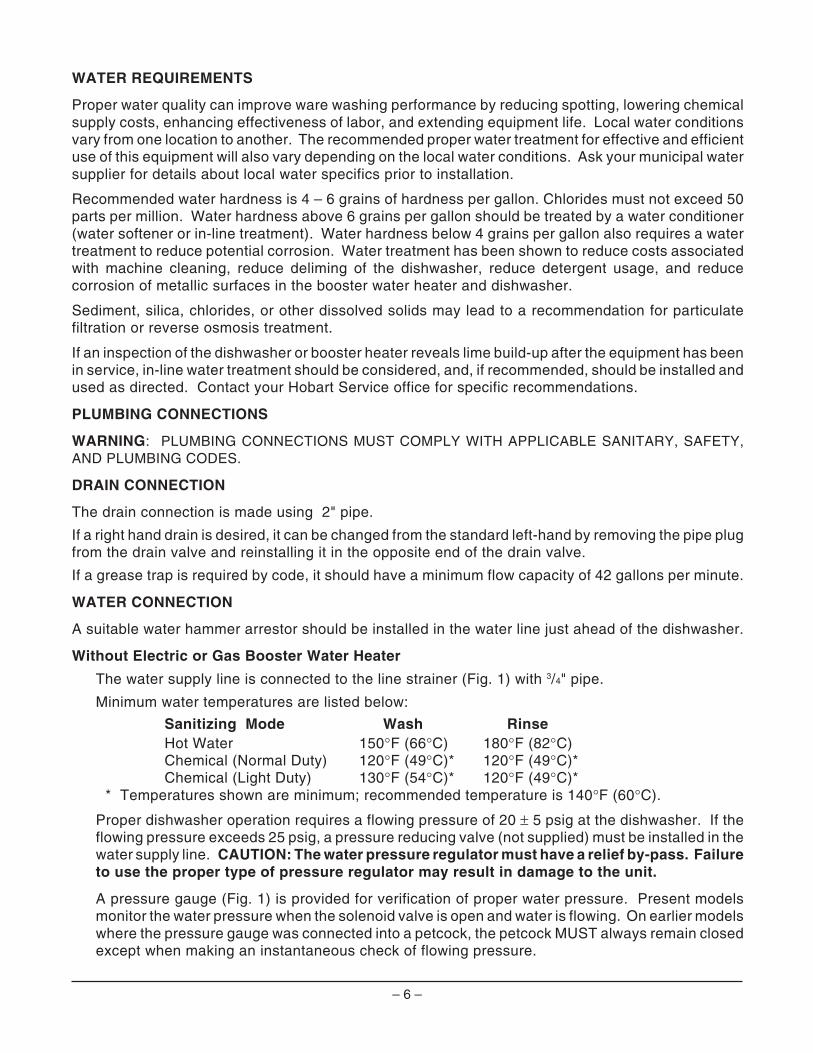
Check the gas data plate attached to thedishwasher or the tag attached to the incominggas piping for the type of gas to be used.Connect the gas supply to the 1/2" NPT gasinlet at the manual gas valve. The burner isnot adjustable. The maximum flowing inletgas pressure must not exceed the Maximumvalue in the table. If line pressure exceedsthe Maximum value in the table, an additionalregulator valve (not supplied) must be installedin the supply line.
Static inlet line pressure should not exceed 14" W.C. The minimum value isfor purpose of input adjustment.
The gas valve (Fig. 3) is provided with a pressure tap to measure the gaspressure downstream, which is also the manifold pressure. Gas supply pipingmust have a sediment trap (supplied by others) installed ahead of thedishwasher's gas control (Fig. 3).
NOTE: DO NOT use Teflon tape on gas line pipe threads. For gas line pipeconnections, use LOCTITE 565, Hobart part 546292, or a flexible sealantsuitable for use with Natural and Propane Gases.
The appliance and its gas connections must be leak tested before placing theappliance in operation. Use soapy water for leak test. DO NOT use openflame. The installation must conform with local codes, or in the absence oflocal codes, with the National Fuel Gas Code, ANSI Z223.1 (latest edition).Copies may be obtained from American Gas Association, Inc., 1515 WilsonBlvd., Arlington, VA 22209.
The appliance and its individual shutoff valve must be disconnected from the gas supply piping systemduring any pressure testing of that system at test pressures in excess of 1/2 psig (3.45kPa).
The appliance must be isolated from the gas supply piping system by closing its individual manualshutoff valve during any pressure testing of the gas supply piping system at test pressures equal to orless than 1/2 psig (3.45kPa).
Dissipate test pressure from the gas supply line before re-connecting the appliance and its manualshutoff valve to the gas supply line. Caution: Failure to follow this procedure may damage the gasvalve.
NOITACIFICEPSERUSSERPSAG[ GNIWOLF GNIWOLF GNIWOLF GNIWOLF GNIWOLF ]CITATSTON—ERUSSERPSAG ]CITATSTON—ERUSSERPSAG ]CITATSTON—ERUSSERPSAG ]CITATSTON—ERUSSERPSAG ]CITATSTON—ERUSSERPSAG
ledoM ledoM ledoM ledoM ledoMepyT epyT epyT epyT epyT
fofofofofosaG saG saG saG saG
RH/UTB RH/UTB RH/UTB RH/UTB RH/UTB
)nmuloCretaW(.C.WsehcnI )nmuloCretaW(.C.WsehcnI )nmuloCretaW(.C.WsehcnI )nmuloCretaW(.C.WsehcnI )nmuloCretaW(.C.WsehcnI
erusserPeniLgnimocnI erusserPeniLgnimocnI erusserPeniLgnimocnI erusserPeniLgnimocnI erusserPeniLgnimocnI dlofinaM dlofinaM dlofinaM dlofinaM dlofinaMerusserP erusserP erusserP erusserP erusserPmuminiM muminiM muminiM muminiM muminiM mumixaM mumixaM mumixaM mumixaM mumixaM
C41MA
larutaN 000,02 5.4 5.01 2.3
enaporP 000,02 0.9 0.31 0.9
Fig. 3
PL-53347
By Others
Sediment Trap
Gas Valve
Manual Valve
– 8 –
The dishwasher must be installed so that the flow of combustion and ventilation air will not beobstructed. Adequate clearances for air openings into the combustion chamber must be provided.Make sure there is an adequate supply of make-up air in the room to allow for combustion of the gasat the burner(s).
Keep the appliance area free and clear from all combustible substances. Do not obstruct the flow ofcombustion and ventilation air. The dishwasher must have a minimum clearance from combustibleconstruction of 1 inch from the flue at the rear and 0 inches at the sides. A clearance of 40 inches mustbe provided at the front of the dishwasher for servicing and proper operation.
The burner is ignited automatically by solid state electronic circuitry; there is no pilot light. Gas flowis regulated by the temperature control circuit.
VENTING REQUIREMENTS — WITH GAS TANK HEAT
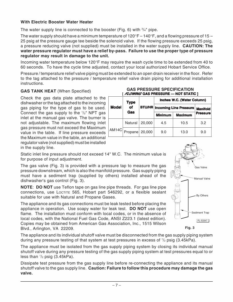
The Hobart AM14 / AM14C dishwasher equipped for gas tank heat is not provided with a flue collar andis not intended to have the flue directly connected to a ventilation system. However, the products ofcombustion must be vented to the outside air. The most common method of venting is a vent hood overthe entire dishwasher (Fig. 4). Refer to Rate of Exhaust Flow Calculations on the next page forcalculations of the proper vent rate for your hood. Another method is a small vent hood (Fig. 5)positioned about five inches above the flue exit at the rear of the dishwasher and connected to existingductwork. In either case, an electrical interlock must be provided to allow the flow of gas to thedishwasher burner ONLY when the exhaust system is energized. For additional information, refer tothe National Fuel Gas Code, ANSI Z223.1, NFPA 54.
• IMPORTANT: Make sure the installation meets the local code for your area.
Fig. 4 Fig. 5
31/2"
6" ➤
➤
➤ ➤
➤
➤
4"
➤ 3" x 3" DUCT INTOCURRENT SYSTEM
➤
5" GAPMINIMUM
➤
➤MINI VENT HOOD
DISHWASHER FLUE EXIT➤
➤
➤
6"MINIMUMOVERHANGON ALL SIDES
➤
➤
1' TO 4'CLEARANCE
➤
➤18" OVERHANGRECOMMENDEDOVER LOADING ORUNLOADING DOORS
– 9 –
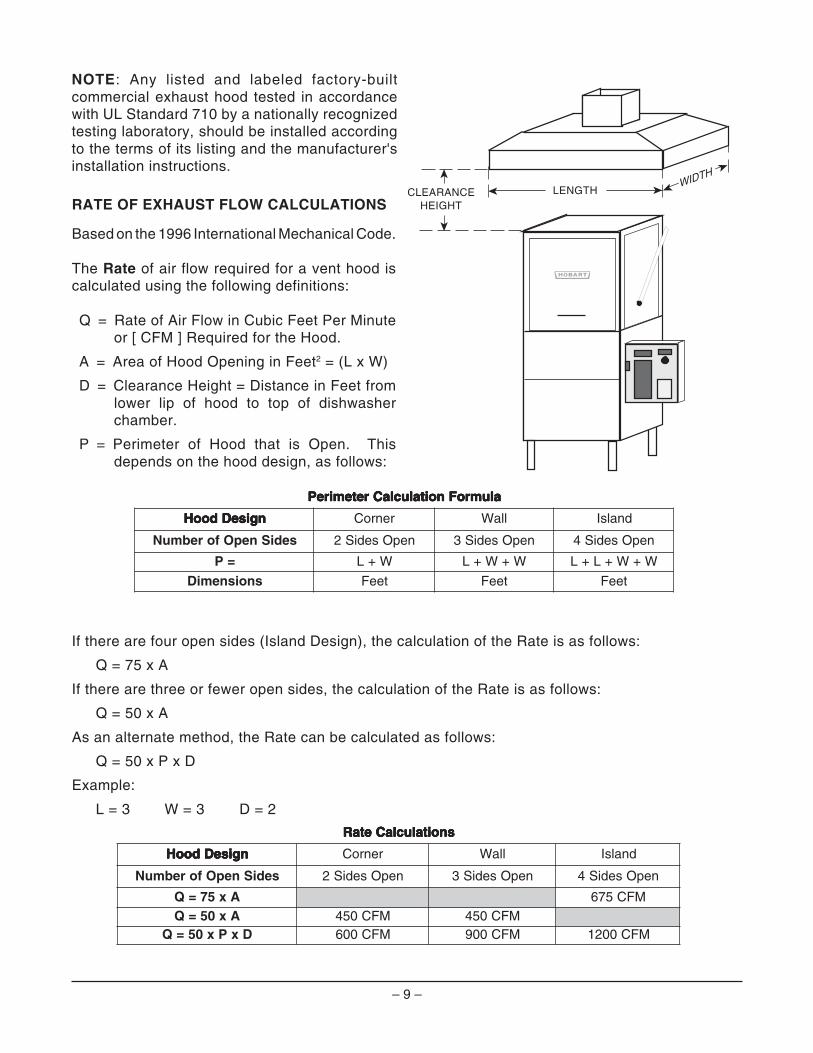
RATE OF EXHAUST FLOW CALCULATIONS
Based on the 1996 International Mechanical Code.
The Rate of air flow required for a vent hood iscalculated using the following definitions:
Q = Rate of Air Flow in Cubic Feet Per Minuteor [ CFM ] Required for the Hood.
A = Area of Hood Opening in Feet2 = (L x W)
D = Clearance Height = Distance in Feet fromlower lip of hood to top of dishwasherchamber.
P = Perimeter of Hood that is Open. Thisdepends on the hood design, as follows:
If there are four open sides (Island Design), the calculation of the Rate is as follows:
Q = 75 x A
If there are three or fewer open sides, the calculation of the Rate is as follows:
Q = 50 x A
As an alternate method, the Rate can be calculated as follows:
Q = 50 x P x D
Example:
L = 3 W = 3 D = 2
alumroFnoitaluclaCretemireP alumroFnoitaluclaCretemireP alumroFnoitaluclaCretemireP alumroFnoitaluclaCretemireP alumroFnoitaluclaCretemireP
ngiseDdooH ngiseDdooH ngiseDdooH ngiseDdooH ngiseDdooH renroC llaW dnalsI
sediSnepOforebmuN nepOsediS2 nepOsediS3 nepOsediS4
=P W+L W+W+L W+W+L+L
snoisnemiD teeF teeF teeF
snoitaluclaCetaR snoitaluclaCetaR snoitaluclaCetaR snoitaluclaCetaR snoitaluclaCetaR
ngiseDdooH ngiseDdooH ngiseDdooH ngiseDdooH ngiseDdooH renroC llaW dnalsI
sediSnepOforebmuN nepOsediS2 nepOsediS3 nepOsediS4
Ax57=Q MFC576Ax05=Q MFC054 MFC054
DxPx05=Q MFC006 MFC009 MFC0021
NOTE: Any listed and labeled factory-builtcommercial exhaust hood tested in accordancewith UL Standard 710 by a nationally recognizedtesting laboratory, should be installed accordingto the terms of its listing and the manufacturer'sinstallation instructions.
➤
➤
LENGTH
➤
➤
CLEARANCEHEIGHT
➤
➤
WIDTH
– 10 –
STEAM HEAT (When Specified)
A 3/4" union connection for the steam supply line is located at the lower right side of the machine.
The steam supply must have a flowing pressure of 15 – 20 psig.
Steam flow is controlled by a solenoid valve, as well as a mechanical ball valve. The ball valve shouldbe closed when the dishwasher is not in use.
ELECTRICAL CONNECTIONS
WARNING: ELECTRICAL AND GROUNDING CONNECTIONS MUST COMPLY WITH THE APPLICABLEPORTIONS OF THE NATIONAL ELECTRICAL CODE AND/OR OTHER LOCAL ELECTRICAL CODES.
WARNING: DISCONNECT ELECTRICAL POWER SUPPLY AND PLACE A TAG AT THE DISCONNECTSWITCH TO INDICATE THAT YOU ARE WORKING ON THE CIRCUIT.
DISHWASHER CONNECTION
Refer to the wiring diagram attached inside the control box and to the machine data plate for servicesize requirements when connecting the dishwasher. Also, refer to Electrical Data, page 12.
When circuit breaker option is not provided . . . the dishwasher electrical service connections aremade through the 13⁄4" hole in the right-hand bottom of the control box. A fused disconnect switch orcircuit breaker must be installed in the electrical service line supplying this dishwasher and shouldmeet the requirements of your local electrical code. The incoming power supply connections shouldbe made to the terminal block in the control box and a ground lead should be connected to thegrounding lug in the control box if grounding is not provided by the conduit used. When equipped withsingle point electrical connection option for both the dishwasher and electric booster, one incomingelectric supply line should be connected to the terminal block in the control box and a ground leadshould be connected to the grounding lug if grounding is not provided by the conduit used.
When equipped with the circuit breaker option . . . the incoming electrical supply or supplies shouldbe connected to the terminal block in the circuit breaker box on top of the dishwasher. If the electricbooster option is supplied, a separate connection may or may not be required, depending uponwhether or not single point electrical connection option is present. A ground lead should be connectedto the grounding lug if grounding is not provided by the conduit used.
When equipped with both single point electrical connection and circuit breaker options . . .the incoming electric supply should be connected to the terminal block in the circuit breaker box on topof the machine. A ground lead should be connected to the grounding lug if grounding is not providedby the conduit used.
Check Rotation (Three-Phase Machines Only)
Three-phase motors must rotate in the direction of the arrow on the pump housing. In order to checkrotation, the motor fan cover must be removed. Close the machine doors and press the power switchto ON. When the machine is completely filled, place the cycle switch (located on the side of the controlbox) on MANUAL and place the WASH / RINSE switch (located under the cycle switch) on WASH. Themotor fan must rotate in the direction of the arrow on the pump housing.
If the rotation is incorrect, DISCONNECT ELECTRICAL POWER SUPPLY and interchange any twoof the incoming power supply leads. Reconnect the power supply and verify correct rotation. Replacethe motor fan cover.
– 11 –
Electric Booster Water Heater Option
NOTE: Electric Booster electrical connection will be separate from the dishwasher electricalconnection unless single point electrical connection is supplied. If circuit breaker option is provided,the electric supply or supplies are connected to the circuit breaker box on top of the dishwasher.
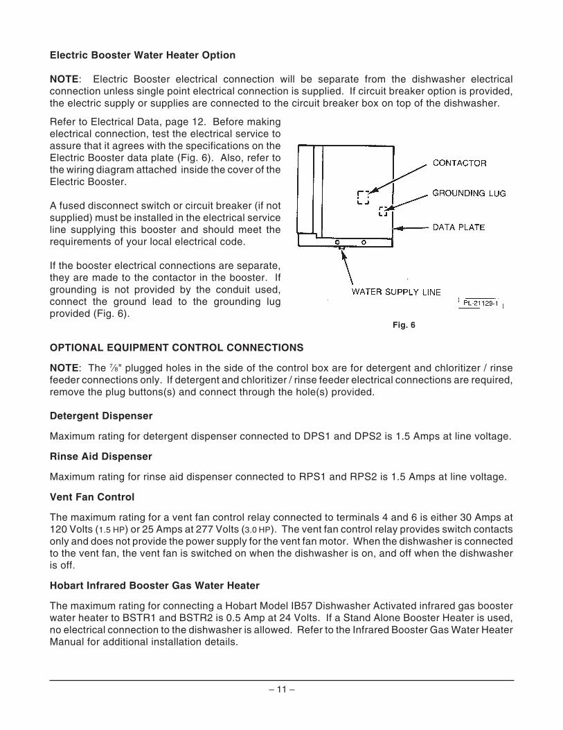
Refer to Electrical Data, page 12. Before makingelectrical connection, test the electrical service toassure that it agrees with the specifications on theElectric Booster data plate (Fig. 6). Also, refer tothe wiring diagram attached inside the cover of theElectric Booster.
A fused disconnect switch or circuit breaker (if notsupplied) must be installed in the electrical serviceline supplying this booster and should meet therequirements of your local electrical code.
If the booster electrical connections are separate,they are made to the contactor in the booster. Ifgrounding is not provided by the conduit used,connect the ground lead to the grounding lugprovided (Fig. 6).
Fig. 6
OPTIONAL EQUIPMENT CONTROL CONNECTIONS
NOTE: The 7⁄8" plugged holes in the side of the control box are for detergent and chloritizer / rinsefeeder connections only. If detergent and chloritizer / rinse feeder electrical connections are required,remove the plug buttons(s) and connect through the hole(s) provided.
Detergent Dispenser
Maximum rating for detergent dispenser connected to DPS1 and DPS2 is 1.5 Amps at line voltage.
Rinse Aid Dispenser
Maximum rating for rinse aid dispenser connected to RPS1 and RPS2 is 1.5 Amps at line voltage.
Vent Fan Control
The maximum rating for a vent fan control relay connected to terminals 4 and 6 is either 30 Amps at120 Volts (1.5 HP) or 25 Amps at 277 Volts (3.0 HP). The vent fan control relay provides switch contactsonly and does not provide the power supply for the vent fan motor. When the dishwasher is connectedto the vent fan, the vent fan is switched on when the dishwasher is on, and off when the dishwasheris off.
Hobart Infrared Booster Gas Water Heater
The maximum rating for connecting a Hobart Model IB57 Dishwasher Activated infrared gas boosterwater heater to BSTR1 and BSTR2 is 0.5 Amp at 24 Volts. If a Stand Alone Booster Heater is used,no electrical connection to the dishwasher is allowed. Refer to the Infrared Booster Gas Water HeaterManual for additional installation details.
– 12 –
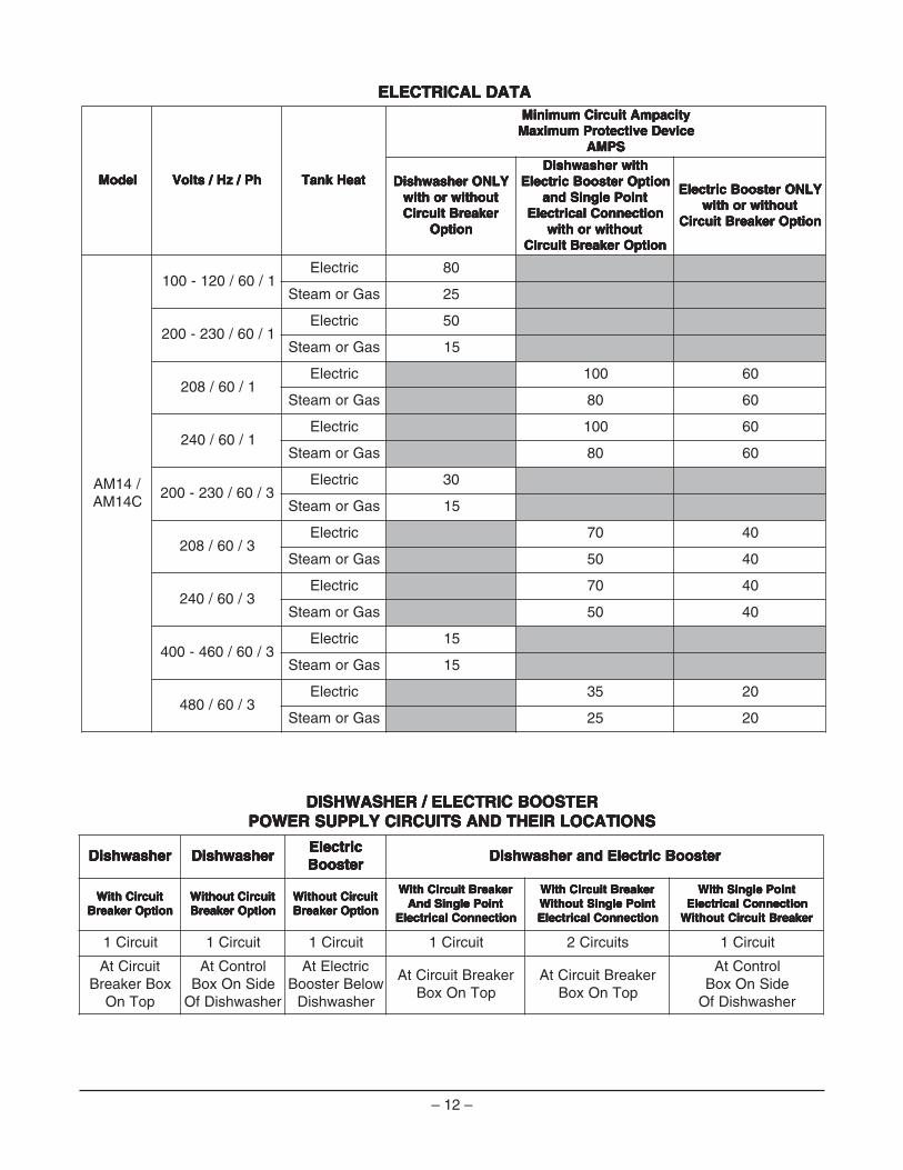
ATADLACIRTCELE ATADLACIRTCELE ATADLACIRTCELE ATADLACIRTCELE ATADLACIRTCELE
ledoM ledoM ledoM ledoM ledoM hP/zH/stloV hP/zH/stloV hP/zH/stloV hP/zH/stloV hP/zH/stloV taeHknaT taeHknaT taeHknaT taeHknaT taeHknaT
yticapmAtiucriCmuminiM yticapmAtiucriCmuminiM yticapmAtiucriCmuminiM yticapmAtiucriCmuminiM yticapmAtiucriCmuminiMeciveDevitcetorPmumixaM eciveDevitcetorPmumixaM eciveDevitcetorPmumixaM eciveDevitcetorPmumixaM eciveDevitcetorPmumixaM
SPMA SPMA SPMA SPMA SPMA
YLNOrehsawhsiD YLNOrehsawhsiD YLNOrehsawhsiD YLNOrehsawhsiD YLNOrehsawhsiDtuohtiwrohtiw tuohtiwrohtiw tuohtiwrohtiw tuohtiwrohtiw tuohtiwrohtiwrekaerBtiucriC rekaerBtiucriC rekaerBtiucriC rekaerBtiucriC rekaerBtiucriC
noitpO noitpO noitpO noitpO noitpO
htiwrehsawhsiD htiwrehsawhsiD htiwrehsawhsiD htiwrehsawhsiD htiwrehsawhsiDnoitpOretsooBcirtcelE noitpOretsooBcirtcelE noitpOretsooBcirtcelE noitpOretsooBcirtcelE noitpOretsooBcirtcelE
tnioPelgniSdna tnioPelgniSdna tnioPelgniSdna tnioPelgniSdna tnioPelgniSdnanoitcennoClacirtcelE noitcennoClacirtcelE noitcennoClacirtcelE noitcennoClacirtcelE noitcennoClacirtcelE
tuohtiwrohtiw tuohtiwrohtiw tuohtiwrohtiw tuohtiwrohtiw tuohtiwrohtiwnoitpOrekaerBtiucriC noitpOrekaerBtiucriC noitpOrekaerBtiucriC noitpOrekaerBtiucriC noitpOrekaerBtiucriC
YLNOretsooBcirtcelE YLNOretsooBcirtcelE YLNOretsooBcirtcelE YLNOretsooBcirtcelE YLNOretsooBcirtcelEtuohtiwrohtiw tuohtiwrohtiw tuohtiwrohtiw tuohtiwrohtiw tuohtiwrohtiw
noitpOrekaerBtiucriC noitpOrekaerBtiucriC noitpOrekaerBtiucriC noitpOrekaerBtiucriC noitpOrekaerBtiucriC
/41MAC41MA
1/06/021-001cirtcelE 08
saGromaetS 52
1/06/032-002cirtcelE 05
saGromaetS 51
1/06/802cirtcelE 001 06
saGromaetS 08 06
1/06/042cirtcelE 001 06
saGromaetS 08 06
3/06/032-002cirtcelE 03
saGromaetS 51
3/06/802cirtcelE 07 04
saGromaetS 05 04
3/06/042cirtcelE 07 04
saGromaetS 05 04
3/06/064-004cirtcelE 51
saGromaetS 51
3/06/084cirtcelE 53 02
saGromaetS 52 02
RETSOOBCIRTCELE/REHSAWHSID RETSOOBCIRTCELE/REHSAWHSID RETSOOBCIRTCELE/REHSAWHSID RETSOOBCIRTCELE/REHSAWHSID RETSOOBCIRTCELE/REHSAWHSIDSNOITACOLRIEHTDNASTIUCRICYLPPUSREWOP SNOITACOLRIEHTDNASTIUCRICYLPPUSREWOP SNOITACOLRIEHTDNASTIUCRICYLPPUSREWOP SNOITACOLRIEHTDNASTIUCRICYLPPUSREWOP SNOITACOLRIEHTDNASTIUCRICYLPPUSREWOP
rehsawhsiD rehsawhsiD rehsawhsiD rehsawhsiD rehsawhsiD rehsawhsiD rehsawhsiD rehsawhsiD rehsawhsiD rehsawhsiDcirtcelE cirtcelE cirtcelE cirtcelE cirtcelEretsooB retsooB retsooB retsooB retsooB
retsooBcirtcelEdnarehsawhsiD retsooBcirtcelEdnarehsawhsiD retsooBcirtcelEdnarehsawhsiD retsooBcirtcelEdnarehsawhsiD retsooBcirtcelEdnarehsawhsiD
tiucriChtiW tiucriChtiW tiucriChtiW tiucriChtiW tiucriChtiWnoitpOrekaerB noitpOrekaerB noitpOrekaerB noitpOrekaerB noitpOrekaerB
tiucriCtuohtiW tiucriCtuohtiW tiucriCtuohtiW tiucriCtuohtiW tiucriCtuohtiWnoitpOrekaerB noitpOrekaerB noitpOrekaerB noitpOrekaerB noitpOrekaerB
tiucriCtuohtiW tiucriCtuohtiW tiucriCtuohtiW tiucriCtuohtiW tiucriCtuohtiWnoitpOrekaerB noitpOrekaerB noitpOrekaerB noitpOrekaerB noitpOrekaerB
rekaerBtiucriChtiW rekaerBtiucriChtiW rekaerBtiucriChtiW rekaerBtiucriChtiW rekaerBtiucriChtiWtnioPelgniSdnA tnioPelgniSdnA tnioPelgniSdnA tnioPelgniSdnA tnioPelgniSdnA
noitcennoClacirtcelE noitcennoClacirtcelE noitcennoClacirtcelE noitcennoClacirtcelE noitcennoClacirtcelE
rekaerBtiucriChtiW rekaerBtiucriChtiW rekaerBtiucriChtiW rekaerBtiucriChtiW rekaerBtiucriChtiWtnioPelgniStuohtiW tnioPelgniStuohtiW tnioPelgniStuohtiW tnioPelgniStuohtiW tnioPelgniStuohtiWnoitcennoClacirtcelE noitcennoClacirtcelE noitcennoClacirtcelE noitcennoClacirtcelE noitcennoClacirtcelE
tnioPelgniShtiW tnioPelgniShtiW tnioPelgniShtiW tnioPelgniShtiW tnioPelgniShtiWnoitcennoClacirtcelE noitcennoClacirtcelE noitcennoClacirtcelE noitcennoClacirtcelE noitcennoClacirtcelE
rekaerBtiucriCtuohtiW rekaerBtiucriCtuohtiW rekaerBtiucriCtuohtiW rekaerBtiucriCtuohtiW rekaerBtiucriCtuohtiW
tiucriC1 tiucriC1 tiucriC1 tiucriC1 stiucriC2 tiucriC1
tiucriCtAxoBrekaerB
poTnO
lortnoCtAediSnOxoB
rehsawhsiDfO
cirtcelEtAwoleBretsooBrehsawhsiD
rekaerBtiucriCtApoTnOxoB
rekaerBtiucriCtApoTnOxoB
lortnoCtAediSnOxoB
rehsawhsiDfO
– 13 –
OPERATIONPREPARATION
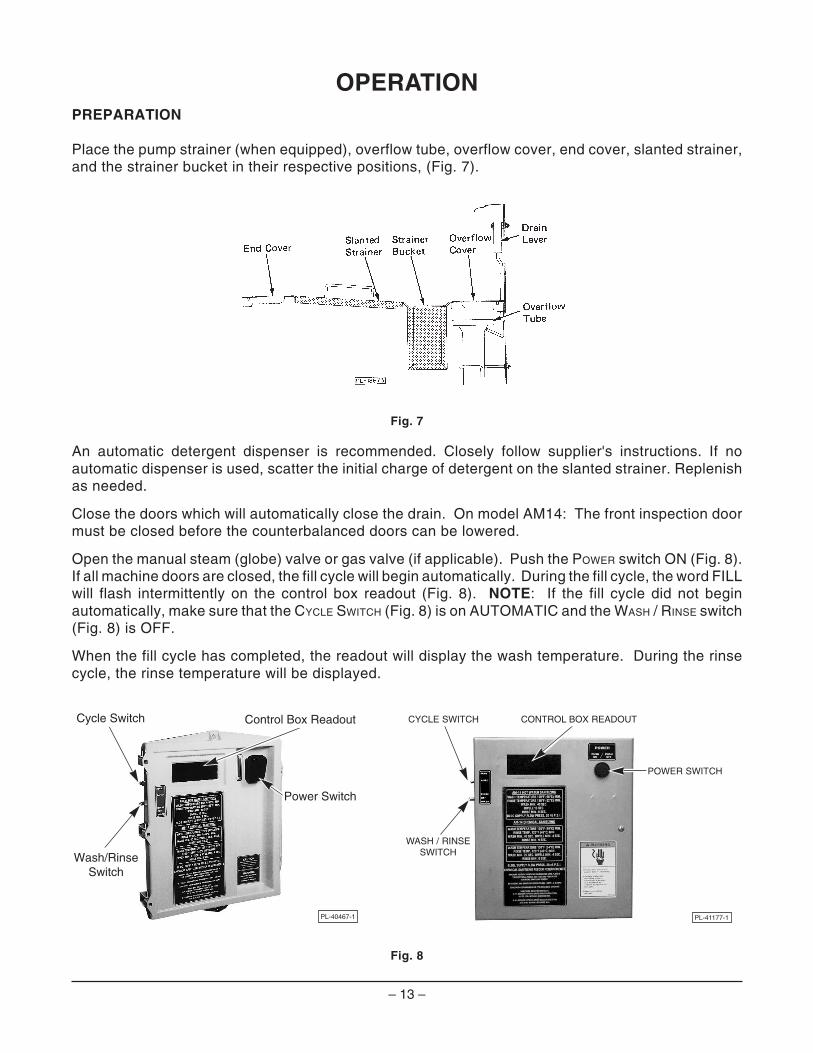
Place the pump strainer (when equipped), overflow tube, overflow cover, end cover, slanted strainer,and the strainer bucket in their respective positions, (Fig. 7).
Fig. 7
An automatic detergent dispenser is recommended. Closely follow supplier's instructions. If noautomatic dispenser is used, scatter the initial charge of detergent on the slanted strainer. Replenishas needed.
Close the doors which will automatically close the drain. On model AM14: The front inspection doormust be closed before the counterbalanced doors can be lowered.
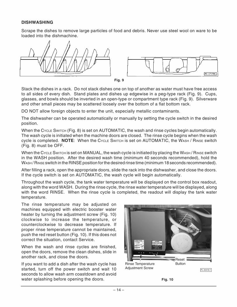
Open the manual steam (globe) valve or gas valve (if applicable). Push the POWER switch ON (Fig. 8).If all machine doors are closed, the fill cycle will begin automatically. During the fill cycle, the word FILLwill flash intermittently on the control box readout (Fig. 8). NOTE: If the fill cycle did not beginautomatically, make sure that the CYCLE SWITCH (Fig. 8) is on AUTOMATIC and the WASH / RINSE switch(Fig. 8) is OFF.
When the fill cycle has completed, the readout will display the wash temperature. During the rinsecycle, the rinse temperature will be displayed.
Fig. 8
PL-40467-1
Control Box Readout
Power Switch
Cycle Switch
Wash/RinseSwitch
WASH / RINSESWITCH
POWER SWITCH
PL-41177-1
CYCLE SWITCH CONTROL BOX READOUT
– 14 –
PL-40416-1
ResetButtonRinse Temperature
Adjustment Screw
DISHWASHING
Scrape the dishes to remove large particles of food and debris. Never use steel wool on ware to beloaded into the dishmachine.
Fig. 9
Stack the dishes in a rack. Do not stack dishes one on top of another as water must have free accessto all sides of every dish. Stand plates and dishes up edgewise in a peg-type rack (Fig. 9). Cups,glasses, and bowls should be inverted in an open-type or compartment type rack (Fig. 9). Silverwareand other small pieces may be scattered loosely over the bottom of a flat bottom rack.
DO NOT allow foreign objects to enter the unit, especially metallic contaminants.
The dishwasher can be operated automatically or manually by setting the cycle switch in the desiredposition.
When the CYCLE SWITCH (Fig. 8) is set on AUTOMATIC, the wash and rinse cycles begin automatically.The wash cycle is initiated when the machine doors are closed. The rinse cycle begins when the washcycle is completed. NOTE: When the CYCLE SWITCH is set on AUTOMATIC, the WASH / RINSE switch(Fig. 8) must be OFF.
When the CYCLE SWITCH is set on MANUAL, the wash cycle is initiated by placing the WASH / RINSE switchin the WASH position. After the desired wash time (minimum 40 seconds recommended), hold theWASH / RINSE switch in the RINSE position for the desired rinse time (minimum 18 seconds recommended).
After filling a rack, open the appropriate doors, slide the rack into the dishwasher, and close the doors.If the cycle switch is set on AUTOMATIC, the wash cycle will begin automatically.
Throughout the wash cycle, the tank water temperature will be displayed on the control box readout,along with the word WASH. During the rinse cycle, the rinse water temperature will be displayed, alongwith the word RINSE. When the rinse cycle is completed, the readout will display the tank watertemperature.
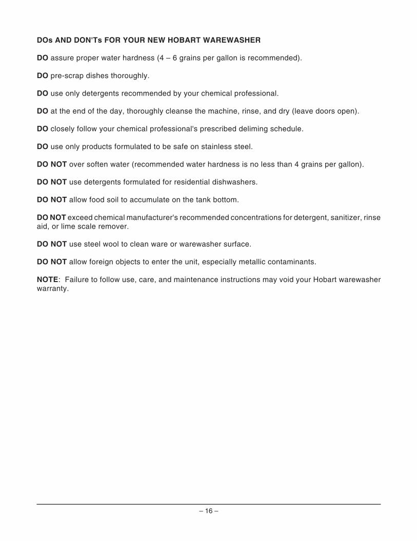
The rinse temperature may be adjusted onmachines equipped with electric booster waterheater by turning the adjustment screw (Fig. 10)clockwise to increase the temperature, orcounterclockwise to decrease temperature. Ifproper rinse temperature cannot be maintained,push the red reset button (Fig. 10). If this does notcorrect the situation, contact Service.
When the wash and rinse cycles are finished,open the doors, remove the clean dishes, slide inanother rack, and close the doors.
If you want to add a dish after the wash cycle hasstarted, turn off the power switch and wait 10seconds to allow wash arm coastdown and avoidwater splashing before opening the doors. Fig. 10
– 15 –
CLEANING
The machine must be thoroughly cleaned at the end of each working shift or at least daily. Never use steelwool to clean warewasher surfaces. Use only products formulated to be safe on stainless steel.
Turn off the power switch.
If the machine has steam heat, close the manually operated steam (ball) valve.
Open the machine doors.
Clean off the dish tables into the dishwasher.
Drain the machine by pulling the drain lever (Fig. 7).
Remove and empty the slanted strainer and strainer bucket. Wash and rinse them thoroughly.
Raise the overflow cover and remove the overflow tube. Wash and rinse the overflow tube inside and out.
Remove the pump strainer (if equipped) and clean in a sink.
Thoroughly cleanse and flush the dishwasher interior. Remove remaining soil with a soft cloth or brushand mild cleanser. Rinse again. Do not allow food soil to accumulate on the tank bottom.
Replace all removed parts.
Leave the machine doors open to allow the interior to dry and air out.
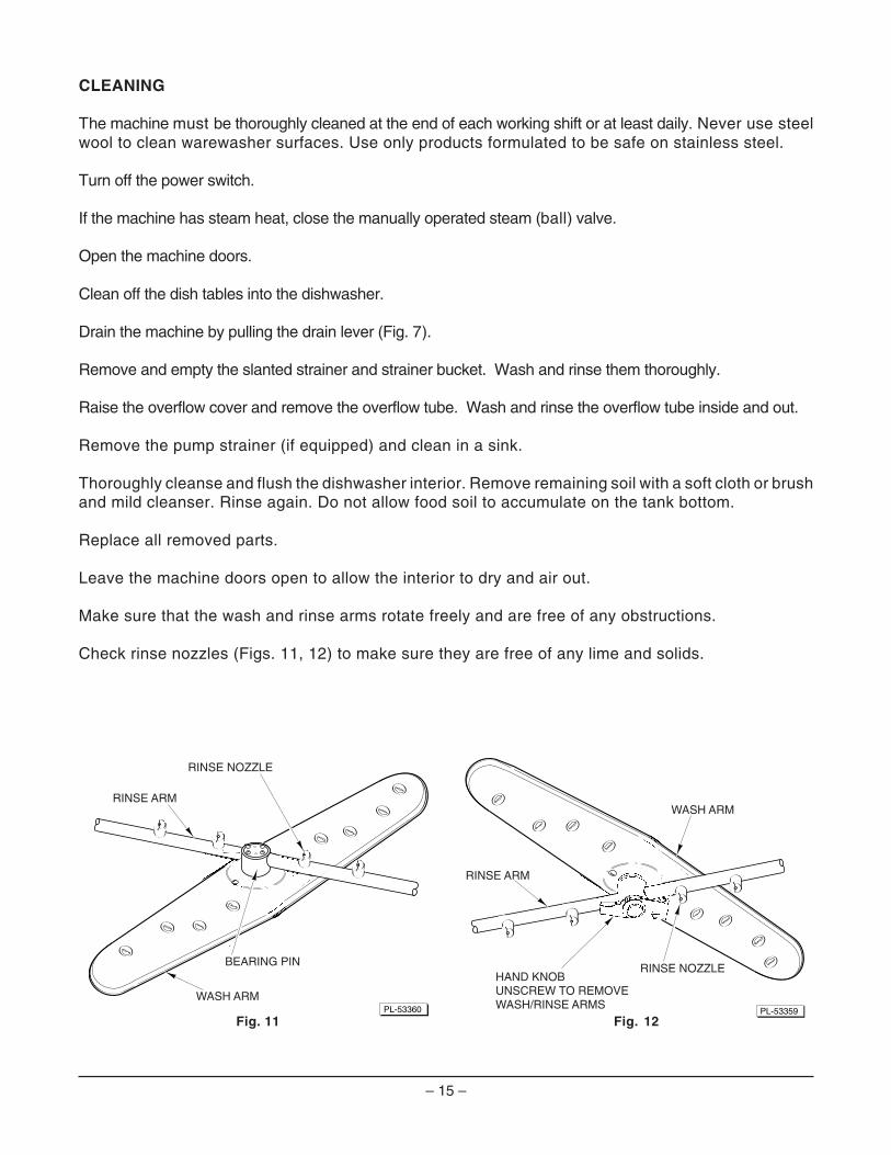
Make sure that the wash and rinse arms rotate freely and are free of any obstructions.
Check rinse nozzles (Figs. 11, 12) to make sure they are free of any lime and solids.
Fig. 11 Fig. 12PL-53360
RINSE ARM
RINSE NOZZLE
WASH ARM
BEARING PIN
PL-53359
HAND KNOBUNSCREW TO REMOVEWASH/RINSE ARMS
RINSE ARM
RINSE NOZZLE
WASH ARM
– 16 –
DOs AND DON'Ts FOR YOUR NEW HOBART WAREWASHER
DO assure proper water hardness (4 – 6 grains per gallon is recommended).
DO pre-scrap dishes thoroughly.
DO use only detergents recommended by your chemical professional.
DO at the end of the day, thoroughly cleanse the machine, rinse, and dry (leave doors open).
DO closely follow your chemical professional's prescribed deliming schedule.
DO use only products formulated to be safe on stainless steel.
DO NOT over soften water (recommended water hardness is no less than 4 grains per gallon).
DO NOT use detergents formulated for residential dishwashers.
DO NOT allow food soil to accumulate on the tank bottom.
DO NOT exceed chemical manufacturer's recommended concentrations for detergent, sanitizer, rinseaid, or lime scale remover.
DO NOT use steel wool to clean ware or warewasher surface.
DO NOT allow foreign objects to enter the unit, especially metallic contaminants.
NOTE: Failure to follow use, care, and maintenance instructions may void your Hobart warewasherwarranty.
– 17 –
MAINTENANCE
WARNING: DISCONNECT ELECTRICAL POWER SUPPLY (BOTH DISHWASHER AND BOOSTERIF APPLICABLE) AND PLACE A TAG(S) AT THE DISCONNECT SWITCH(ES) TO INDICATE THECIRCUIT(S) ARE BEING WORKED ON BEFORE BEGINNING ANY MAINTENANCE PROCEDURE.
WASH ARMS
Upper and lower wash and rinse arms (Figs. 11, 12) should turn freely and continue turning for a fewseconds after being whirled by hand. To check, DISCONNECT ELECTRICAL POWER SUPPLY(BOTH DISHWASHER AND BOOSTER IF APPLICABLE), rotate arms, and remove any obstructionscausing improper operation.
If the slanted strainer or strainer bucket is not properly in place, obstructions (such as food particlesor bones) may clog the wash arm nozzles. The wash arms are easily removed for cleaning.
Removing Wash / Rinse Arms — AM14 / AM14C
To remove the lower wash arm, first lift off the rinse arm; then, using a dowel (or end of punch),unscrew the rinse arm bearing pin (Fig. 11) and lift off the lower wash arm. It is not necessaryto remove the spacer located on the lower wash arm shaft.
The upper wash and rinse arms are removed by unscrewing the hand knob (Fig. 12) and loweringboth arms together. Be careful not to drop these arms.
MOTOR(S)
The wash pump motor and the blower motor used on gas heat machines are equipped withpermanently lubricated bearings and require no lubrication maintenance.
GAS FLUE (Machines equipped for gas heat only.)
When cool, check the flue opening every three months for obstructions.
TROUBLESHOOTING
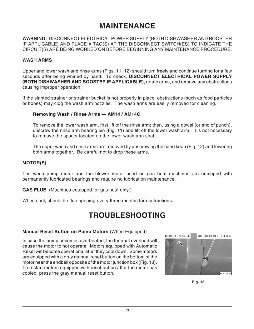
Manual Reset Button on Pump Motors (When Equipped)
In case the pump becomes overheated, the thermal overload willcause the motor to not operate. Motors equipped with AutomaticReset will become operational after they cool down. Some motorsare equipped with a gray manual reset button on the bottom of themotor near the endbell opposite of the motor junction box (Fig. 13).To restart motors equipped with reset button after the motor hascooled, press the gray manual reset button.
Fig. 13
PL-41450-1
MOTOR ENDBELL MOTOR RESET BUTTON
– 18 –
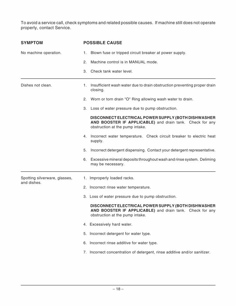
To avoid a service call, check symptoms and related possible causes. If machine still does not operateproperly, contact Service.
SYMPTOM POSSIBLE CAUSE
No machine operation. 1. Blown fuse or tripped circuit breaker at power supply.
2. Machine control is in MANUAL mode.
3. Check tank water level.
Dishes not clean. 1. Insufficient wash water due to drain obstruction preventing proper drainclosing.
2. Worn or torn drain "O" Ring allowing wash water to drain.
3. Loss of water pressure due to pump obstruction.
DISCONNECT ELECTRICAL POWER SUPPLY (BOTH DISHWASHERAND BOOSTER IF APPLICABLE) and drain tank. Check for anyobstruction at the pump intake.
4. Incorrect water temperature. Check circuit breaker to electric heatsupply.
5. Incorrect detergent dispensing. Contact your detergent representative.
6. Excessive mineral deposits throughout wash and rinse system. Delimingmay be necessary.
Spotting silverware, glasses, 1. Improperly loaded racks.and dishes.
2. Incorrect rinse water temperature.
3. Loss of water pressure due to pump obstruction.
DISCONNECT ELECTRICAL POWER SUPPLY (BOTH DISHWASHERAND BOOSTER IF APPLICABLE) and drain tank. Check for anyobstruction at the pump intake.
4. Excessively hard water.
5. Incorrect detergent for water type.
6. Incorrect rinse additive for water type.
7. Incorrect concentration of detergent, rinse additive and/or sanitizer.
– 19 –
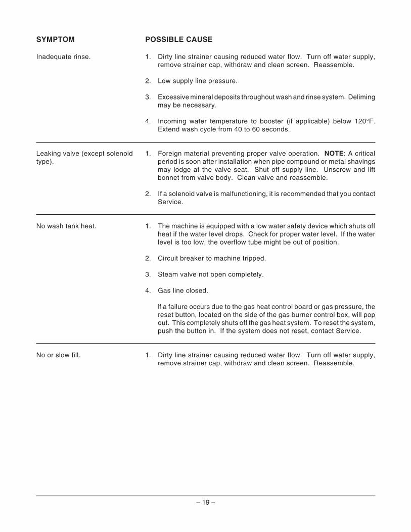
SYMPTOM POSSIBLE CAUSE
Inadequate rinse. 1. Dirty line strainer causing reduced water flow. Turn off water supply,remove strainer cap, withdraw and clean screen. Reassemble.
2. Low supply line pressure.
3. Excessive mineral deposits throughout wash and rinse system. Delimingmay be necessary.
4. Incoming water temperature to booster (if applicable) below 120°F.Extend wash cycle from 40 to 60 seconds.
Leaking valve (except solenoid 1. Foreign material preventing proper valve operation. NOTE: A criticalperiod is soon after installation when pipe compound or metal shavingsmay lodge at the valve seat. Shut off supply line. Unscrew and liftbonnet from valve body. Clean valve and reassemble.
type).
2. If a solenoid valve is malfunctioning, it is recommended that you contactService.
No wash tank heat. 1. The machine is equipped with a low water safety device which shuts offheat if the water level drops. Check for proper water level. If the waterlevel is too low, the overflow tube might be out of position.
2. Circuit breaker to machine tripped.
3. Steam valve not open completely.
4. Gas line closed.
If a failure occurs due to the gas heat control board or gas pressure, thereset button, located on the side of the gas burner control box, will popout. This completely shuts off the gas heat system. To reset the system,push the button in. If the system does not reset, contact Service.
No or slow fill. 1. Dirty line strainer causing reduced water flow. Turn off water supply,remove strainer cap, withdraw and clean screen. Reassemble.
– 20 –
SERVICE
Contact your local Hobart-authorized service office for any repairs or adjustments needed on thisequipment. If a gas orifice fitting is to be adjusted or replaced, have it serviced by qualified Hobart-authorized service personnel. Long-term service contracts are available on this and other Hobartproducts.
FORM 34123 Rev. C (Oct. 2000) PRINTED IN U.S.A.