model assignment 2
TRANSCRIPT
8/16/2019 Model Assignment 2
http://slidepdf.com/reader/full/model-assignment-2 1/24
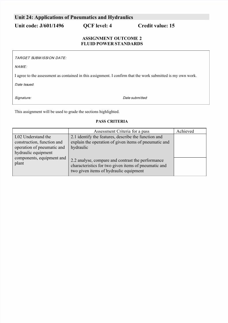
Unit 24: Applications of Pneumatics and Hydraulics
Unit code: J/601/1496 QCF level: 4 Credit value: 15
ASSIGNMENT OUTCOME 2
FLUID POWER STANDARDS
TARGET SUBM ISSION DATE:
NAME:
I agree to the assessment as contained in this assignment. I confirm that the work submitted is my own work.
Date Issued :
Signature: Date submitted:
This assignment will be used to grade the sections highlighted.
PASS CRITERIA
Assessment Criteria for a pass Achieved
L02 Understand the
construction, function and
operation of pneumatic and
hydraulic equipment
components, equipment and
plant
2.1 identify the features, describe the function and
explain the operation of given items of pneumatic and
hydraulic
2.2 analyse, compare and contrast the performance
characteristics for two given items of pneumatic and
two given items of hydraulic equipment
8/16/2019 Model Assignment 2
http://slidepdf.com/reader/full/model-assignment-2 2/24
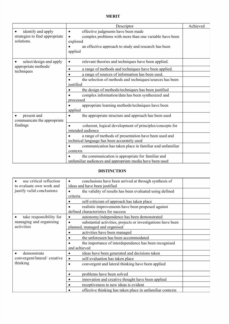
MERIT
Descriptor Achieved
identify and apply
strategies to find appropriate
solutions.
effective judgments have been made
complex problems with more than one variable have been
explored
an effective approach to study and research has been
applied
select/design and apply
appropriate methods/
techniques
relevant theories and techniques have been applied.
a range of methods and techniques have been applied.
a range of sources of information has been used.
the selection of methods and techniques/sources has been
justified
the design of methods/techniques has been justified
complex information/data has been synthesized and
processed
appropriate learning methods/techniques have been
applied
present and
communicate the appropriate
findings
the appropriate structure and approach has been used
coherent, logical development of principles/concepts for
intended audience
a range of methods of presentation have been used and
technical language has been accurately used
communication has taken place in familiar and unfamiliar
contexts
the communication is appropriate for familiar and
unfamiliar audiences and appropriate media have been used
DISTINCTION
use critical reflection
to evaluate own work and
justify valid conclusions
conclusions have been arrived at through synthesis of
ideas and have been justified
the validity of results has been evaluated using defined
criteria
self-criticism of approach has taken place
realistic improvements have been proposed against
defined characteristics for success
take responsibility for
managing and organising
activities
autonomy/independence has been demonstrated
substantial activities, projects or investigations have been
planned, managed and organised activities have been managed
the unforeseen has been accommodated
the importance of interdependence has been recognised
and achieved
demonstrate
convergent/lateral/ creative
thinking
ideas have been generated and decisions taken
self-evaluation has taken place
convergent and lateral thinking have been applied
problems have been solved
innovation and creative thought have been applied
receptiveness to new ideas is evident effective thinking has taken place in unfamiliar contexts
8/16/2019 Model Assignment 2
http://slidepdf.com/reader/full/model-assignment-2 3/24
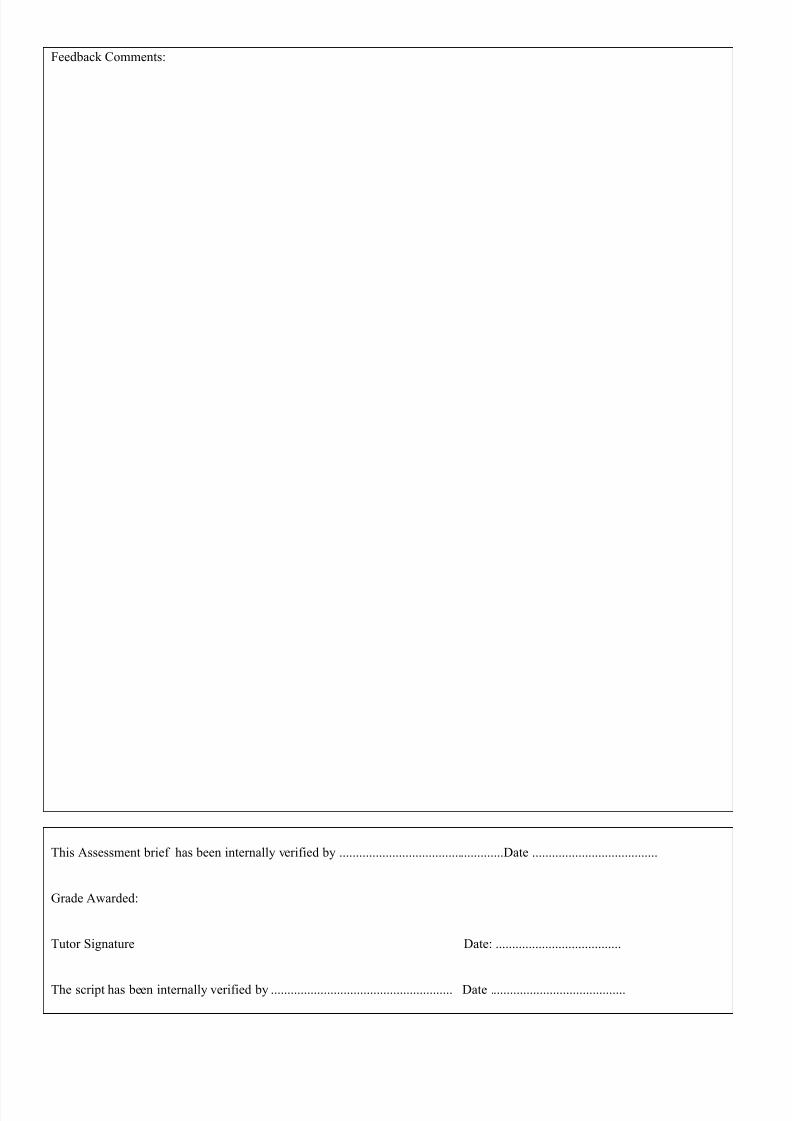
Feedback Comments:
This Assessment brief has been internally verified by ..................................................Date ......................................
Grade Awarded:
Tutor Signature Date: ......................................
The script has been internally verified by ....................................................... Date .........................................
8/16/2019 Model Assignment 2
http://slidepdf.com/reader/full/model-assignment-2 4/24
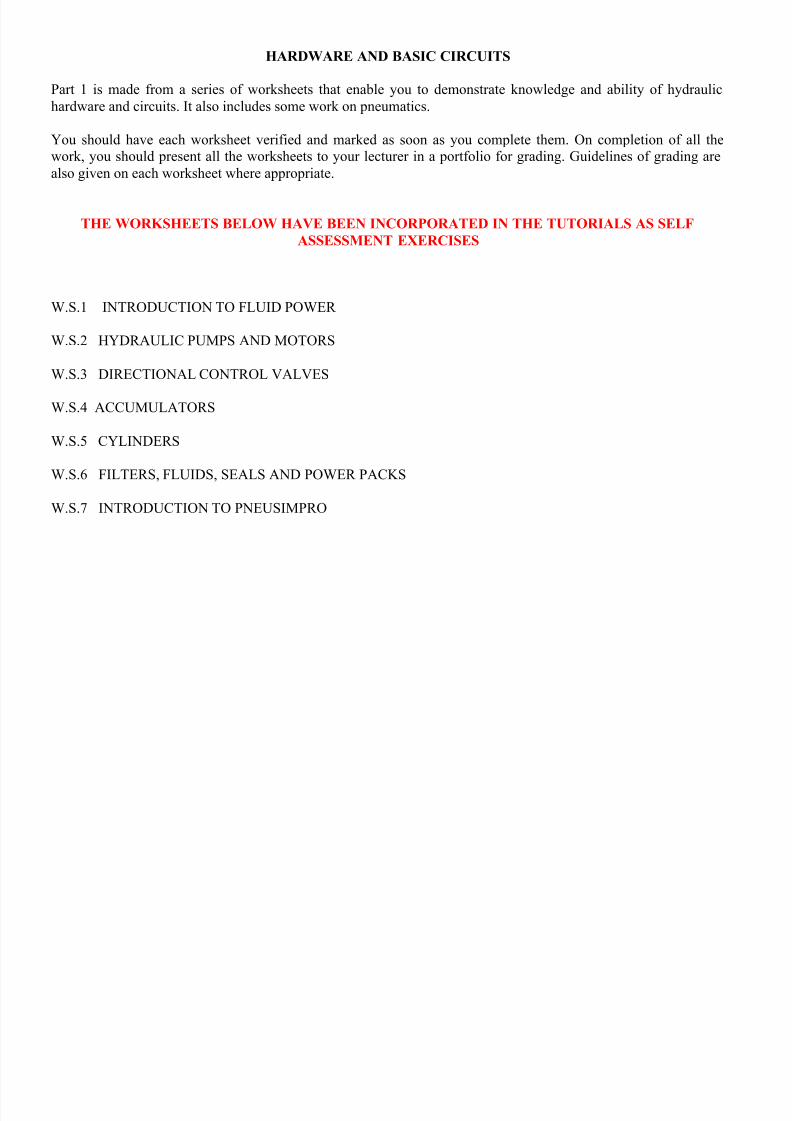
HARDWARE AND BASIC CIRCUITS
Part 1 is made from a series of worksheets that enable you to demonstrate knowledge and ability of hydraulic
hardware and circuits. It also includes some work on pneumatics.
You should have each worksheet verified and marked as soon as you complete them. On completion of all the
work, you should present all the worksheets to your lecturer in a portfolio for grading. Guidelines of grading are
also given on each worksheet where appropriate.
THE WORKSHEETS BELOW HAVE BEEN INCORPORATED IN THE TUTORIALS AS SELF
ASSESSMENT EXERCISES
W.S.1 INTRODUCTION TO FLUID POWER
W.S.2 HYDRAULIC PUMPS AND MOTORS
W.S.3 DIRECTIONAL CONTROL VALVES
W.S.4 ACCUMULATORS
W.S.5 CYLINDERS
W.S.6 FILTERS, FLUIDS, SEALS AND POWER PACKS
W.S.7 INTRODUCTION TO PNEUSIMPRO
8/16/2019 Model Assignment 2
http://slidepdf.com/reader/full/model-assignment-2 5/24
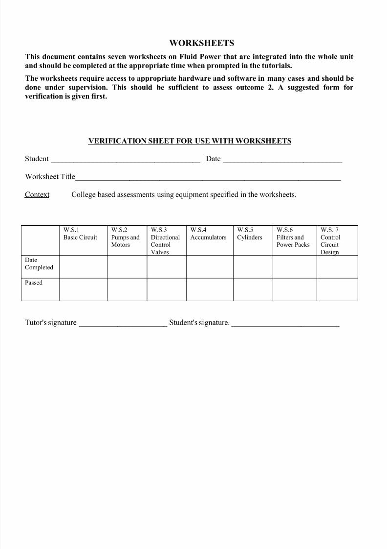
WORKSHEETS
This document contains seven worksheets on Fluid Power that are integrated into the whole unit
and should be completed at the appropriate time when prompted in the tutorials.
The worksheets require access to appropriate hardware and software in many cases and should be
done under supervision. This should be sufficient to assess outcome 2. A suggested form for
verification is given first.
VERIFICATION SHEET FOR USE WITH WORKSHEETS
Student _______________________________________ Date _______________________________
Worksheet Title_____________________________________________________________________
Context College based assessments using equipment specified in the worksheets.
W.S.1
Basic Circuit
W.S.2
Pumps andMotors
W.S.3
DirectionalControl
Valves
W.S.4
Accumulators
W.S.5
Cylinders
W.S.6
Filters andPower Packs
W.S. 7
ControlCircuit
Design
DateCompleted
Passed
Tutor's signature _______________________ Student's signature. ____________________________
8/16/2019 Model Assignment 2
http://slidepdf.com/reader/full/model-assignment-2 6/24
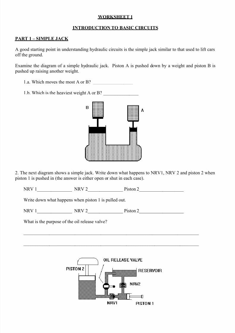
WORKSHEET 1
INTRODUCTION TO BASIC CIRCUITS
PART 1 – SIMPLE JACK
A good starting point in understanding hydraulic circuits is the simple jack similar to that used to lift cars
off the ground.
Examine the diagram of a simple hydraulic jack. Piston A is pushed down by a weight and piston B is
pushed up raising another weight.
1.a. Which moves the most A or B? _________________
1.b. Which is the heaviest weight A or B? _______________
2. The next diagram shows a simple jack. Write down what happens to NRV1, NRV 2 and piston 2 when piston 1 is pushed in (the answer is either open or shut in each case).
NRV 1_______________ NRV 2_______________ Piston 2___________________
Write down what happens when piston 1 is pulled out.
NRV 1_______________ NRV 2_______________ Piston 2___________________
What is the purpose of the oil release valve?
___________________________________________________________________________
___________________________________________________________________________
8/16/2019 Model Assignment 2
http://slidepdf.com/reader/full/model-assignment-2 7/24
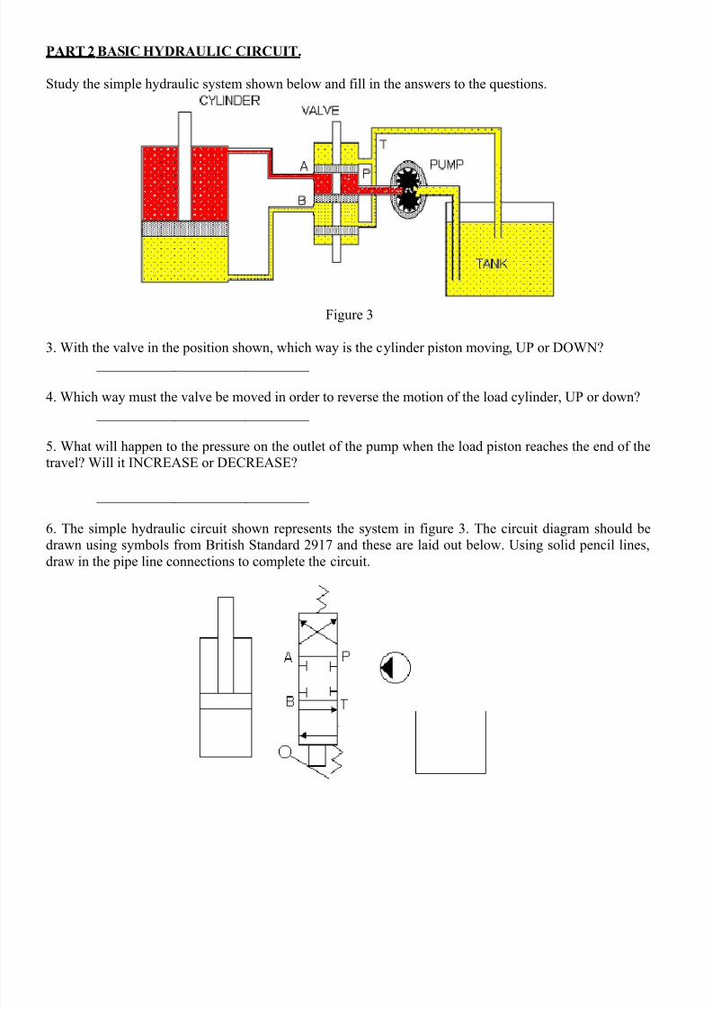
PART 2 BASIC HYDRAULIC CIRCUIT.
Study the simple hydraulic system shown below and fill in the answers to the questions.
Figure 3
3. With the valve in the position shown, which way is the cylinder piston moving, UP or DOWN? ______________________________
4. Which way must the valve be moved in order to reverse the motion of the load cylinder, UP or down?
______________________________
5. What will happen to the pressure on the outlet of the pump when the load piston reaches the end of the
travel? Will it INCREASE or DECREASE?
______________________________
6. The simple hydraulic circuit shown represents the system in figure 3. The circuit diagram should bedrawn using symbols from British Standard 2917 and these are laid out below. Using solid pencil lines,
draw in the pipe line connections to complete the circuit.
8/16/2019 Model Assignment 2
http://slidepdf.com/reader/full/model-assignment-2 8/24
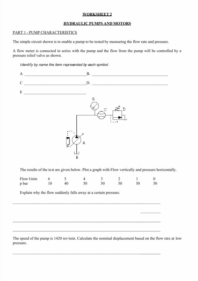
WORKSHEET 2
HYDRAULIC PUMPS AND MOTORS
PART 1 - PUMP CHARACTERISTICS
The simple circuit shown is to enable a pump to be tested by measuring the flow rate and pressure.
A flow meter is connected in series with the pump and the flow from the pump will be controlled by a
pressure relief valve as shown.
I denti fy by name the item represented by each symbol.
A ________________________________B. _______________________________________
C ________________________________D. _______________________________________
E ________________________________
The results of the test are given below. Plot a graph with Flow vertically and pressure horizontally.
Flow l/min 6 5 4 3 2 1 0
p bar 10 40 50 50 50 50 50
Explain why the flow suddenly falls away at a certain pressure.
___________________________________________________________________________
___________________________________________________________________________
___________________________________________________________________________
___________________________________________________________________________
The speed of the pump is 1420 rev/min. Calculate the nominal displacement based on the flow rate at low
pressure.
___________________________________________________________________________
8/16/2019 Model Assignment 2
http://slidepdf.com/reader/full/model-assignment-2 9/24
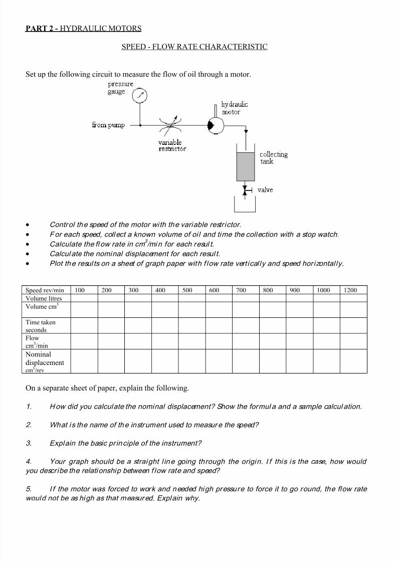
PART 2 - HYDRAULIC MOTORS
SPEED - FLOW RATE CHARACTERISTIC
Set up the following circuit to measure the flow of oil through a motor.
Control the speed of the motor with the variable restr ictor.
For each speed, coll ect a known volume of oi l and time the collection with a stop watch.
Calculate the fl ow rate in cm 3 /min for each resul t.
Calcul ate the nominal displacement for each resul t.
Plot the resul ts on a sheet of graph paper with f low rate vert ical ly and speed horizontal ly.
Speed rev/min 100 200 300 400 500 600 700 800 900 1000 1200
Volume litres
Volume cm3
Time taken
seconds
Flow
cm3/min
Nominal
displacementcm3/rev
On a separate sheet of paper, explain the following.
1. How did you calculate the nominal displacement? Show the formul a and a sample calcul ation.
2. What is the name of the instrument used to measure the speed?
3. Explain the basic pr inciple of the instrument?
4. Your graph should be a straight l ine going through the origin. I f this is the case, how would
you describe the relationship between f low rate and speed?
5. I f the motor was forced to work and needed high pressure to force it to go round, the flow rate
would not be as high as that measured. Explain why.
8/16/2019 Model Assignment 2
http://slidepdf.com/reader/full/model-assignment-2 10/24
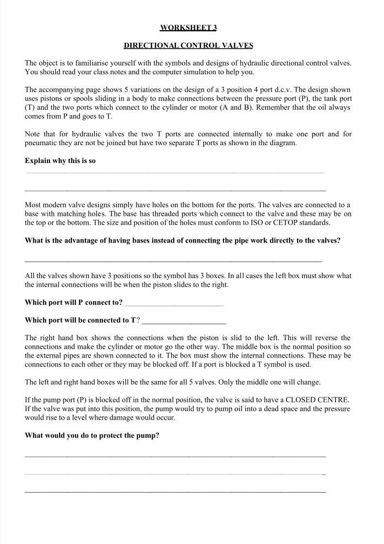
WORKSHEET 3
DIRECTIONAL CONTROL VALVES
The object is to familiarise yourself with the symbols and designs of hydraulic directional control valves.
You should read your class notes and the computer simulation to help you.
The accompanying page shows 5 variations on the design of a 3 position 4 port d.c.v. The design shown
uses pistons or spools sliding in a body to make connections between the pressure port (P), the tank port
(T) and the two ports which connect to the cylinder or motor (A and B). Remember that the oil always
comes from P and goes to T.
Note that for hydraulic valves the two T ports are connected internally to make one port and for
pneumatic they are not be joined but have two separate T ports as shown in the diagram.
Explain why this is so
______________________________________________________________________________
_______________________________________________________________________________
Most modern valve designs simply have holes on the bottom for the ports. The valves are connected to a
base with matching holes. The base has threaded ports which connect to the valve and these may be on
the top or the bottom. The size and position of the holes must conform to ISO or CETOP standards.
What is the advantage of having bases instead of connecting the pipe work directly to the valves?
______________________________________________________________________________
All the valves shown have 3 positions so the symbol has 3 boxes. In all cases the left box must show what
the internal connections will be when the piston slides to the right.
Which port will P connect to? __________________________
Which port will be connected to T? ______________________
The right hand box shows the connections when the piston is slid to the left. This will reverse the
connections and make the cylinder or motor go the other way. The middle box is the normal position so
the external pipes are shown connected to it. The box must show the internal connections. These may be
connections to each other or they may be blocked off. If a port is blocked a T symbol is used.
The left and right hand boxes will be the same for all 5 valves. Only the middle one will change.
If the pump port (P) is blocked off in the normal position, the valve is said to have a CLOSED CENTRE.
If the valve was put into this position, the pump would try to pump oil into a dead space and the pressure
would rise to a level where damage would occur.
What would you do to protect the pump?
_______________________________________________________________________________
_______________________________________________________________________________
_______________________________________________________________________________
8/16/2019 Model Assignment 2
http://slidepdf.com/reader/full/model-assignment-2 11/24
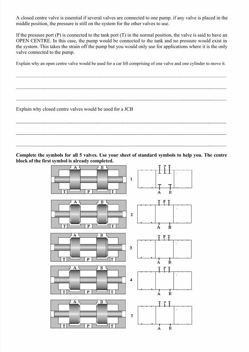
A closed centre valve is essential if several valves are connected to one pump. if any valve is placed in the
middle position, the pressure is still on the system for the other valves to use.
If the pressure port (P) is connected to the tank port (T) in the normal position, the valve is said to have an
OPEN CENTRE. In this case, the pump would be connected to the tank and no pressure would exist in
the system. This takes the strain off the pump but you would only use for applications where it is the only
valve connected to the pump.
Explain why an open centre valve would be used for a car lift comprising of one valve and one cylinder to move it.
_____________________________________________________________________________________
_____________________________________________________________________________________
_____________________________________________________________________________________
Explain why closed centre valves would be used for a JCB
_____________________________________________________________________________________
_____________________________________________________________________________________
_____________________________________________________________________________________
Complete the symbols for all 5 valves. Use your sheet of standard symbols to help you. The centre
block of the first symbol is already completed.
8/16/2019 Model Assignment 2
http://slidepdf.com/reader/full/model-assignment-2 12/24
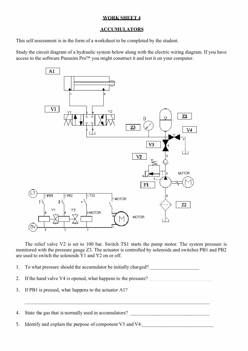
WORK SHEET 4
ACCUMULATORS
This self assessment is in the form of a worksheet to be completed by the student.
Study the circuit diagram of a hydraulic system below along with the electric wiring diagram. If you have
access to the software Pneusim Pro you might construct it and test it on your computer.
The relief valve V2 is set to 100 bar. Switch TS1 starts the pump motor. The system pressure ismonitored with the pressure gauge Z3. The actuator is controlled by solenoids and switches PB1 and PB2
are used to switch the solenoids Y1 and Y2 on or off.
1.
To what pressure should the accumulator be initially charged? ____________________
2.
If the hand valve V4 is opened, what happens to the pressure? __________________________
3. If PB1 is pressed, what happens to the actuator A1?
___________________________________________________________________________
4. State the gas that is normally used in accumulators? ________________________________
5. Identify and explain the purpose of component V3 and V4._____________________________
8/16/2019 Model Assignment 2
http://slidepdf.com/reader/full/model-assignment-2 13/24
___________________________________________________________________________
6. Why is it important that V1 has a closed centre? _____________________________________
____________________________________________________________________________
7. State two reasons for using an accumulator in a system.
____________________________________________________________________________
____________________________________________________________________________
8/16/2019 Model Assignment 2
http://slidepdf.com/reader/full/model-assignment-2 14/24
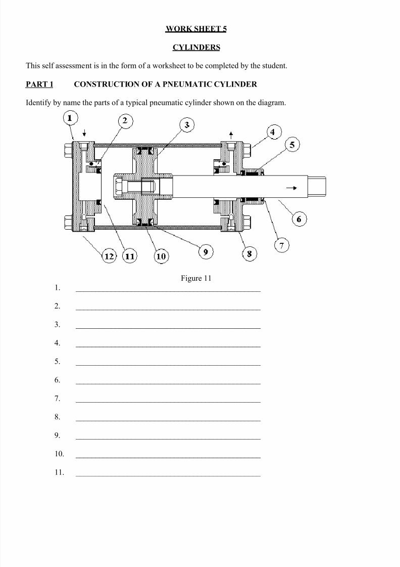
WORK SHEET 5
CYLINDERS
This self assessment is in the form of a worksheet to be completed by the student.
PART 1 CONSTRUCTION OF A PNEUMATIC CYLINDER
Identify by name the parts of a typical pneumatic cylinder shown on the diagram.
Figure 11
1. _______________________________________________
2. _______________________________________________
3. _______________________________________________
4. _______________________________________________
5. _______________________________________________
6. _______________________________________________
7. _______________________________________________
8. _______________________________________________
9. _______________________________________________
10. _______________________________________________
11. _______________________________________________
8/16/2019 Model Assignment 2
http://slidepdf.com/reader/full/model-assignment-2 15/24
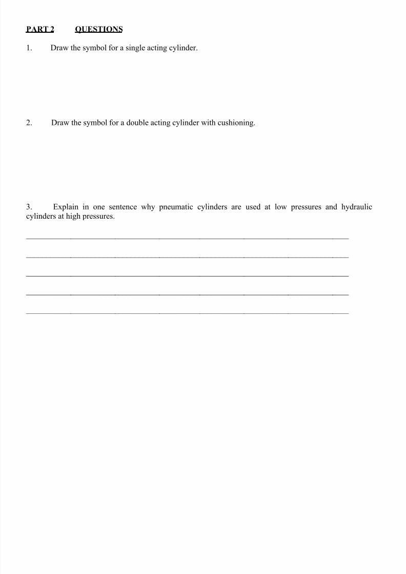
PART 2 QUESTIONS
1. Draw the symbol for a single acting cylinder.
2. Draw the symbol for a double acting cylinder with cushioning.
3. Explain in one sentence why pneumatic cylinders are used at low pressures and hydraulic
cylinders at high pressures.
________________________________________________________________________________
________________________________________________________________________________
________________________________________________________________________________
________________________________________________________________________________
________________________________________________________________________________
8/16/2019 Model Assignment 2
http://slidepdf.com/reader/full/model-assignment-2 16/24
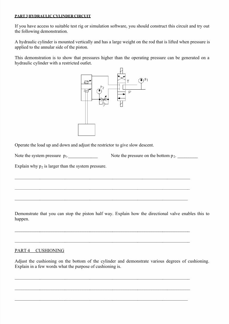
PART 3 HYDRAULIC CYLINDER CIRCUIT
If you have access to suitable test rig or simulation software, you should construct this circuit and try out
the following demonstration.
A hydraulic cylinder is mounted vertically and has a large weight on the rod that is lifted when pressure is
applied to the annular side of the piston.
This demonstration is to show that pressures higher than the operating pressure can be generated on ahydraulic cylinder with a restricted outlet.
Operate the load up and down and adjust the restrictor to give slow descent.
Note the system pressure p1._____________ Note the pressure on the bottom p2. _________
Explain why p2 is larger than the system pressure.
_____________________________________________________________________________
_____________________________________________________________________________
____________________________________________________________________________
Demonstrate that you can stop the piston half way. Explain how the directional valve enables this to
happen.
_____________________________________________________________________________
_____________________________________________________________________________
PART 4 CUSHIONING
Adjust the cushioning on the bottom of the cylinder and demonstrate various degrees of cushioning.
Explain in a few words what the purpose of cushioning is.
_____________________________________________________________________________
_____________________________________________________________________________
____________________________________________________________________________
8/16/2019 Model Assignment 2
http://slidepdf.com/reader/full/model-assignment-2 17/24
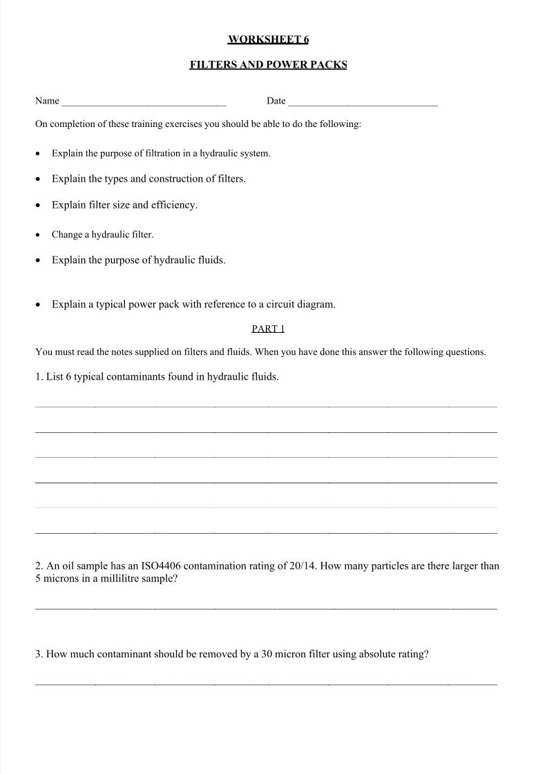
WORKSHEET 6
FILTERS AND POWER PACKS
Name _________________________________ Date ______________________________
On completion of these training exercises you should be able to do the following:
Explain the purpose of filtration in a hydraulic system.
Explain the types and construction of filters.
Explain filter size and efficiency.
Change a hydraulic filter.
Explain the purpose of hydraulic fluids.
Explain a typical power pack with reference to a circuit diagram.
PART 1
You must read the notes supplied on filters and fluids. When you have done this answer the following questions.
1. List 6 typical contaminants found in hydraulic fluids.
_____________________________________________________________________________________
_____________________________________________________________________________________
_____________________________________________________________________________________
_____________________________________________________________________________________
_____________________________________________________________________________________
_____________________________________________________________________________________
2. An oil sample has an ISO4406 contamination rating of 20/14. How many particles are there larger than
5 microns in a millilitre sample?
_____________________________________________________________________________________
3. How much contaminant should be removed by a 30 micron filter using absolute rating?
_____________________________________________________________________________________
8/16/2019 Model Assignment 2
http://slidepdf.com/reader/full/model-assignment-2 18/24
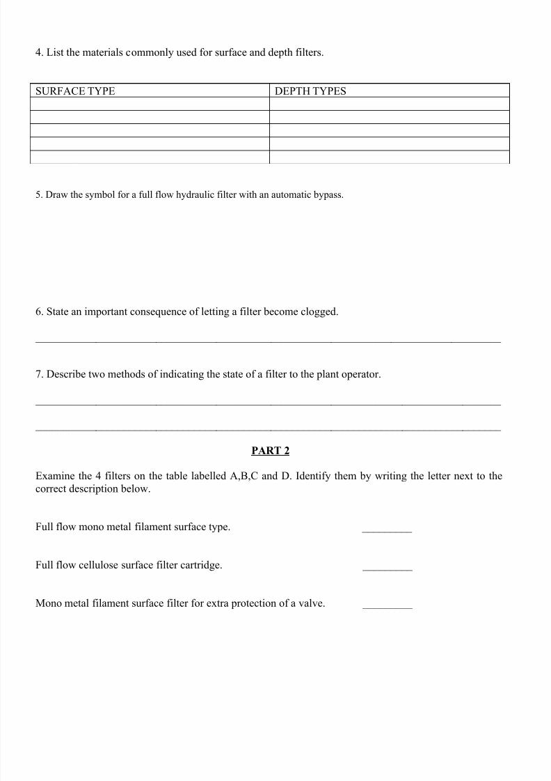
4. List the materials commonly used for surface and depth filters.
SURFACE TYPE DEPTH TYPES
5. Draw the symbol for a full flow hydraulic filter with an automatic bypass.
6. State an important consequence of letting a filter become clogged.
_____________________________________________________________________________________
7. Describe two methods of indicating the state of a filter to the plant operator.
_____________________________________________________________________________________
_____________________________________________________________________________________
PART 2
Examine the 4 filters on the table labelled A,B,C and D. Identify them by writing the letter next to the
correct description below.
Full flow mono metal filament surface type. _________
Full flow cellulose surface filter cartridge. _________
Mono metal filament surface filter for extra protection of a valve. _________
8/16/2019 Model Assignment 2
http://slidepdf.com/reader/full/model-assignment-2 19/24
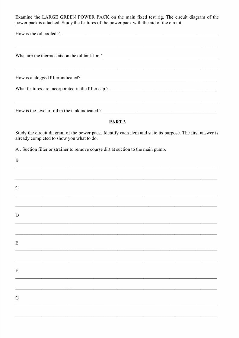
Examine the LARGE GREEN POWER PACK on the main fixed test rig. The circuit diagram of the
power pack is attached. Study the features of the power pack with the aid of the circuit.
How is the oil cooled ? __________________________________________________________________
_____________________________________________________________________________________
What are the thermostats on the oil tank for ? ________________________________________________
_____________________________________________________________________________________
How is a clogged filter indicated? _________________________________________________________
What features are incorporated in the filler cap ? _____________________________________________
_____________________________________________________________________________________
How is the level of oil in the tank indicated ? ________________________________________________
PART 3
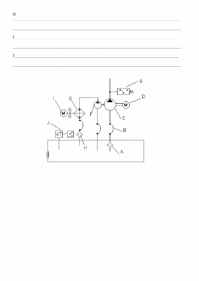
Study the circuit diagram of the power pack. Identify each item and state its purpose. The first answer is
already completed to show you what to do.
A . Suction filter or strainer to remove course dirt at suction to the main pump.
B
_____________________________________________________________________________________
_____________________________________________________________________________________
C
_____________________________________________________________________________________
_____________________________________________________________________________________
D
_____________________________________________________________________________________
_____________________________________________________________________________________
E
_____________________________________________________________________________________
_____________________________________________________________________________________
F
_____________________________________________________________________________________
_____________________________________________________________________________________
G _____________________________________________________________________________________
_____________________________________________________________________________________
8/16/2019 Model Assignment 2
http://slidepdf.com/reader/full/model-assignment-2 20/24
H
_____________________________________________________________________________________
_____________________________________________________________________________________
I___________________________________________________________________________________
_____________________________________________________________________________________
J____________________________________________________________________________________
_____________________________________________________________________________________
8/16/2019 Model Assignment 2
http://slidepdf.com/reader/full/model-assignment-2 21/24
WORKSHEET 7 EXERCISE
Introduction to PneuSim Pro
PneusimPro is a professional software package that enables you to construct various forms of circuits,
programme them and test them by simulation.
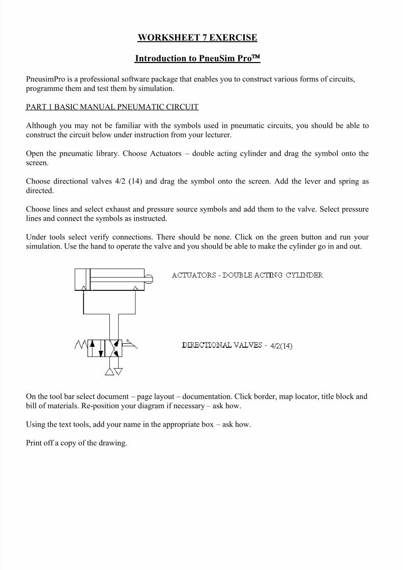
PART 1 BASIC MANUAL PNEUMATIC CIRCUIT
Although you may not be familiar with the symbols used in pneumatic circuits, you should be able to
construct the circuit below under instruction from your lecturer.
Open the pneumatic library. Choose Actuators – double acting cylinder and drag the symbol onto the
screen.
Choose directional valves 4/2 (14) and drag the symbol onto the screen. Add the lever and spring as
directed.
Choose lines and select exhaust and pressure source symbols and add them to the valve. Select pressure
lines and connect the symbols as instructed.
Under tools select verify connections. There should be none. Click on the green button and run your
simulation. Use the hand to operate the valve and you should be able to make the cylinder go in and out.
On the tool bar select document – page layout – documentation. Click border, map locator, title block and bill of materials. Re-position your diagram if necessary – ask how.
Using the text tools, add your name in the appropriate box – ask how.
Print off a copy of the drawing.
8/16/2019 Model Assignment 2
http://slidepdf.com/reader/full/model-assignment-2 22/24
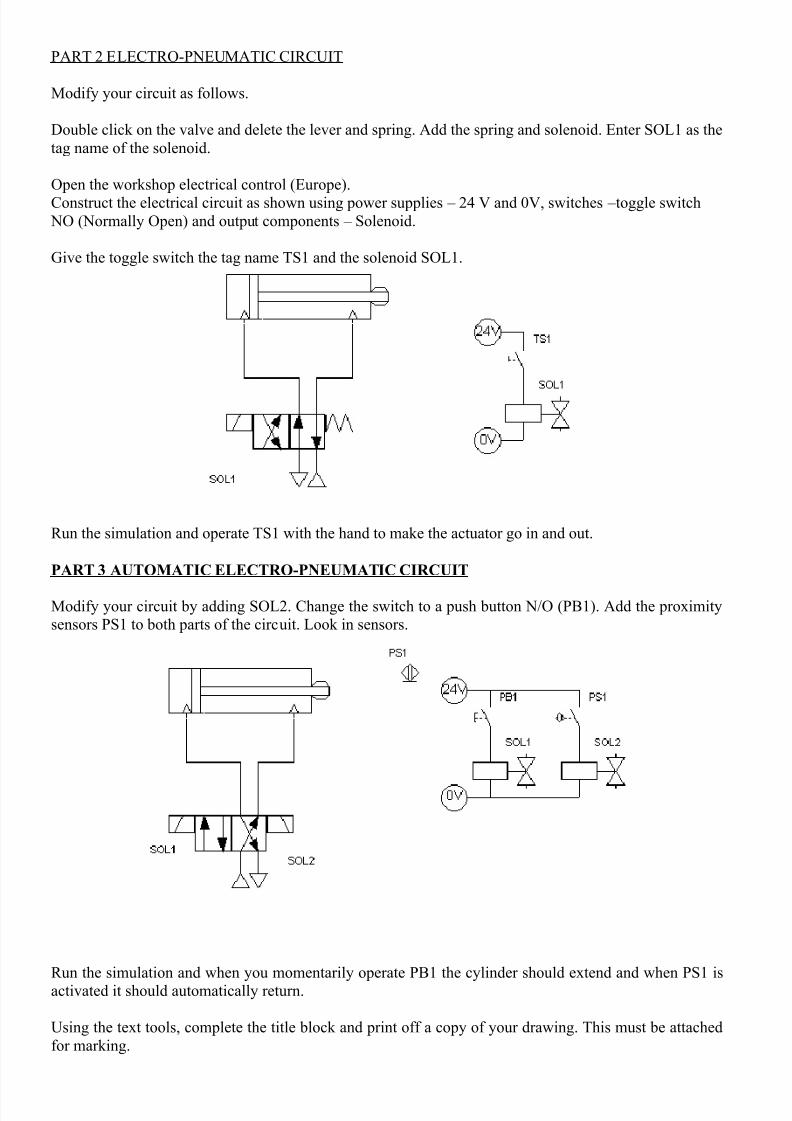
PART 2 ELECTRO-PNEUMATIC CIRCUIT
Modify your circuit as follows.
Double click on the valve and delete the lever and spring. Add the spring and solenoid. Enter SOL1 as the
tag name of the solenoid.
Open the workshop electrical control (Europe).
Construct the electrical circuit as shown using power supplies – 24 V and 0V, switches – toggle switch
NO (Normally Open) and output components – Solenoid.
Give the toggle switch the tag name TS1 and the solenoid SOL1.
Run the simulation and operate TS1 with the hand to make the actuator go in and out.
PART 3 AUTOMATIC ELECTRO-PNEUMATIC CIRCUIT
Modify your circuit by adding SOL2. Change the switch to a push button N/O (PB1). Add the proximity
sensors PS1 to both parts of the circuit. Look in sensors.
Run the simulation and when you momentarily operate PB1 the cylinder should extend and when PS1 is
activated it should automatically return.
Using the text tools, complete the title block and print off a copy of your drawing. This must be attached
for marking.
8/16/2019 Model Assignment 2
http://slidepdf.com/reader/full/model-assignment-2 23/24
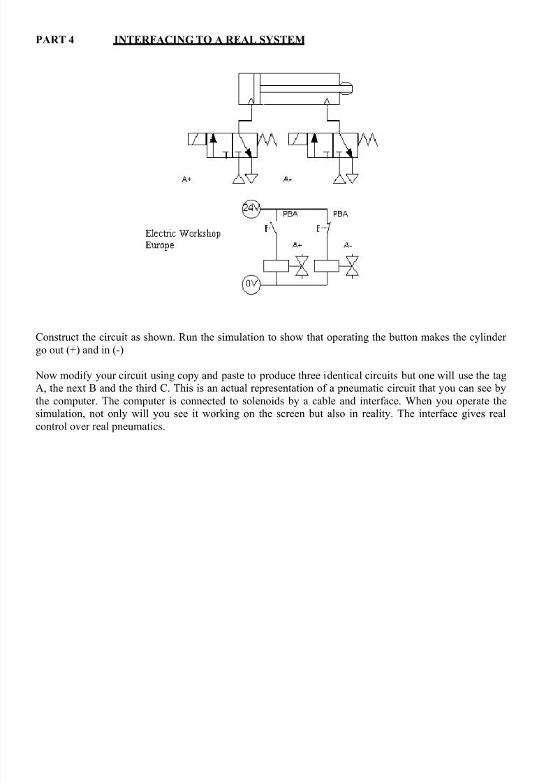
PART 4 INTERFACING TO A REAL SYSTEM
Construct the circuit as shown. Run the simulation to show that operating the button makes the cylinder
go out (+) and in (-)
Now modify your circuit using copy and paste to produce three identical circuits but one will use the tag
A, the next B and the third C. This is an actual representation of a pneumatic circuit that you can see by
the computer. The computer is connected to solenoids by a cable and interface. When you operate the
simulation, not only will you see it working on the screen but also in reality. The interface gives realcontrol over real pneumatics.
8/16/2019 Model Assignment 2
http://slidepdf.com/reader/full/model-assignment-2 24/24
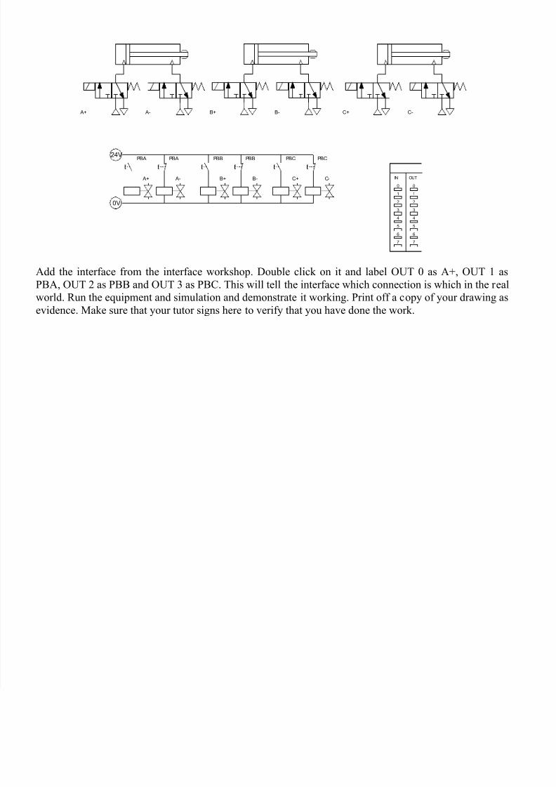
Add the interface from the interface workshop. Double click on it and label OUT 0 as A+, OUT 1 asPBA, OUT 2 as PBB and OUT 3 as PBC. This will tell the interface which connection is which in the real
world. Run the equipment and simulation and demonstrate it working. Print off a copy of your drawing as
evidence. Make sure that your tutor signs here to verify that you have done the work.
24V
0V
IN OUT
0 0
1 1
2 2
3 3
4 4
5 5
6 6
7 7
A+ A- B+ B- C+ C-
PBA
A+
PBA
A-
PBB
B+
PBB
B-
PBC
C+
PBC
C-