model based development and calibration
TRANSCRIPT
1
Model Based Development and Calibration
Guillaume Broustail & Srinivasan Ananthan – AVL UK Expo 2015
AVL UK Expo 2015 2
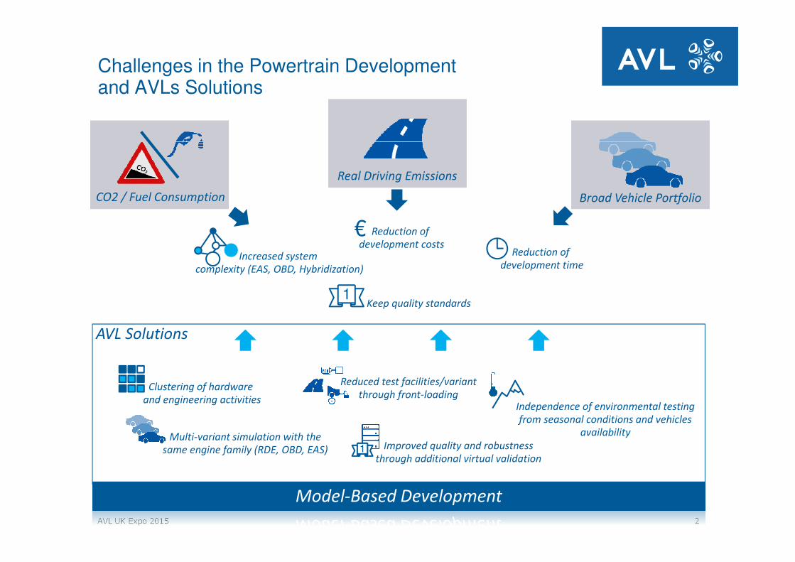
Challenges in the Powertrain Developmentand AVLs Solutions
Model-Based Development
CO2 / Fuel Consumption
Real Driving Emissions
Broad Vehicle Portfolio
AVL Solutions
Reduction of
development costs€
Reduction of
development time
Keep quality standards1
Clustering of hardware
and engineering activities
Increased system
complexity (EAS, OBD, Hybridization)
Multi-variant simulation with the
same engine family (RDE, OBD, EAS)
Reduced test facilities/variant
through front-loading
Improved quality and robustness
through additional virtual validation1
Independence of environmental testing
from seasonal conditions and vehicles
availability

AVL UK Expo 2015 3
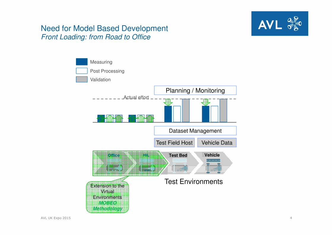
Need for Model Based DevelopmentFront Loading: from Road to Office
Test Field Host
Planning / Monitoring
Test Environments
Actual effort
Vehicle Data
Dataset Management
Measuring
Post Processing
Validation
VehicleTest Bed
AVL UK Expo 2015 4
Need for Model Based DevelopmentFront Loading: from Road to Office
Test Field Host
Planning / Monitoring
Test Environments
Actual effort
Vehicle Data
Dataset Management
Measuring
Post Processing
Validation
VehicleTest Bed
Extension to the Virtual
EnvironmentsMOBEO
Methodology
AVL UK Expo 2015 5
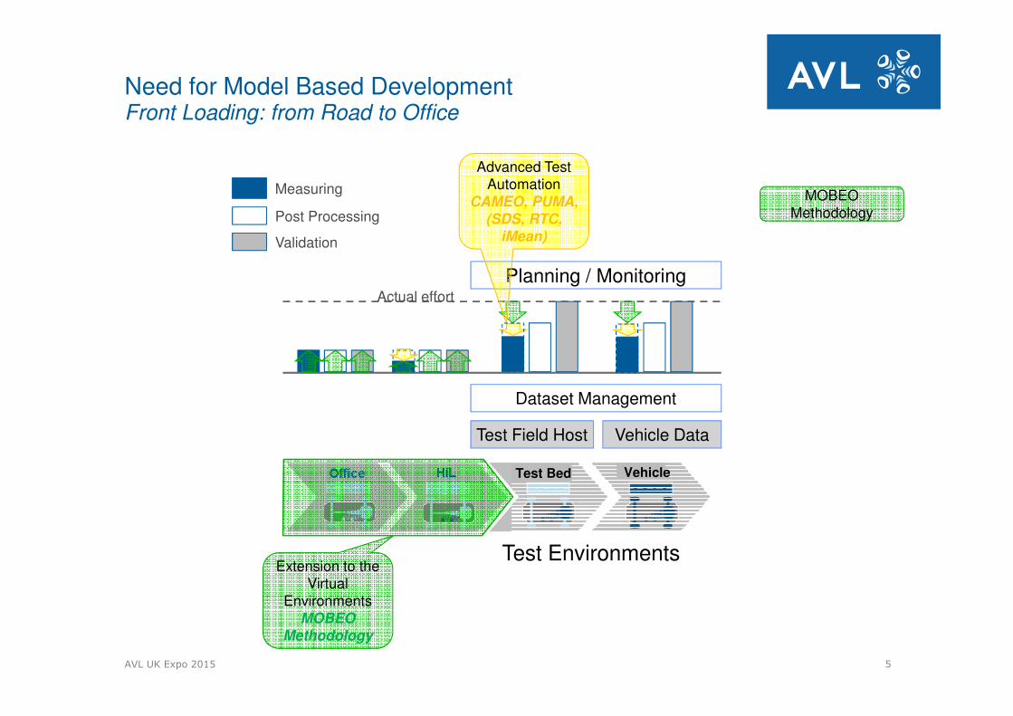
Need for Model Based DevelopmentFront Loading: from Road to Office
Test Field Host
Planning / Monitoring
Test Environments
Actual effort
Vehicle Data
Dataset Management
Measuring
Post Processing
Validation
VehicleTest Bed
Extension to the Virtual
EnvironmentsMOBEO
Methodology
MOBEO Methodology
Advanced Test Automation
CAMEO, PUMA, (SDS, RTC,
iMean)
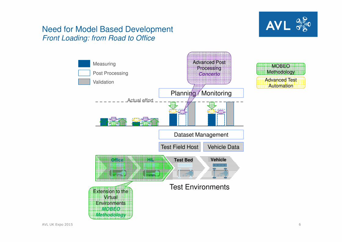
AVL UK Expo 2015 6
Need for Model Based DevelopmentFront Loading: from Road to Office
Test Field Host
Planning / Monitoring
Test Environments
Actual effort
Vehicle Data
Dataset Management
Measuring
Post Processing
Validation
VehicleTest Bed
Extension to the Virtual
EnvironmentsMOBEO
Methodology
MOBEO Methodology
Advanced Post ProcessingConcerto
Advanced Test Automation
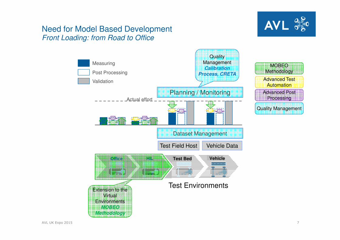
AVL UK Expo 2015 7
Need for Model Based DevelopmentFront Loading: from Road to Office
Test Field Host
Planning / Monitoring
Test Environments
Actual effort
Vehicle Data
Dataset Management
Measuring
Post Processing
Validation
VehicleTest Bed
Extension to the Virtual
EnvironmentsMOBEO
Methodology
MOBEO Methodology
Advanced Test Automation
Quality Management
Advanced Post Processing
Quality ManagementCalibration
Process, CRETA
AVL UK Expo 2015 8
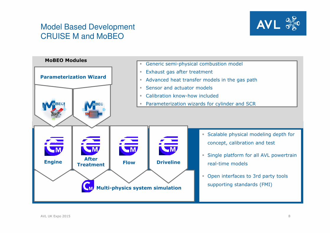
Model Based Development CRUISE M and MoBEO
EngineAfter
Treatment Flow Driveline
� Scalable physical modeling depth for
concept, calibration and test
� Single platform for all AVL powertrain
real-time models
� Open interfaces to 3rd party tools
supporting standards (FMI)
� Generic semi-physical combustion model
� Exhaust gas after treatment
� Advanced heat transfer models in the gas path
� Sensor and actuator models
� Calibration know-how included
� Parameterization wizards for cylinder and SCRModel
MoBEO Modules
Multi-physics system simulation
Parameterization Wizard
AVL UK Expo 2015 9
MOBEO
Model overview
AVL UK Expo 2015 10
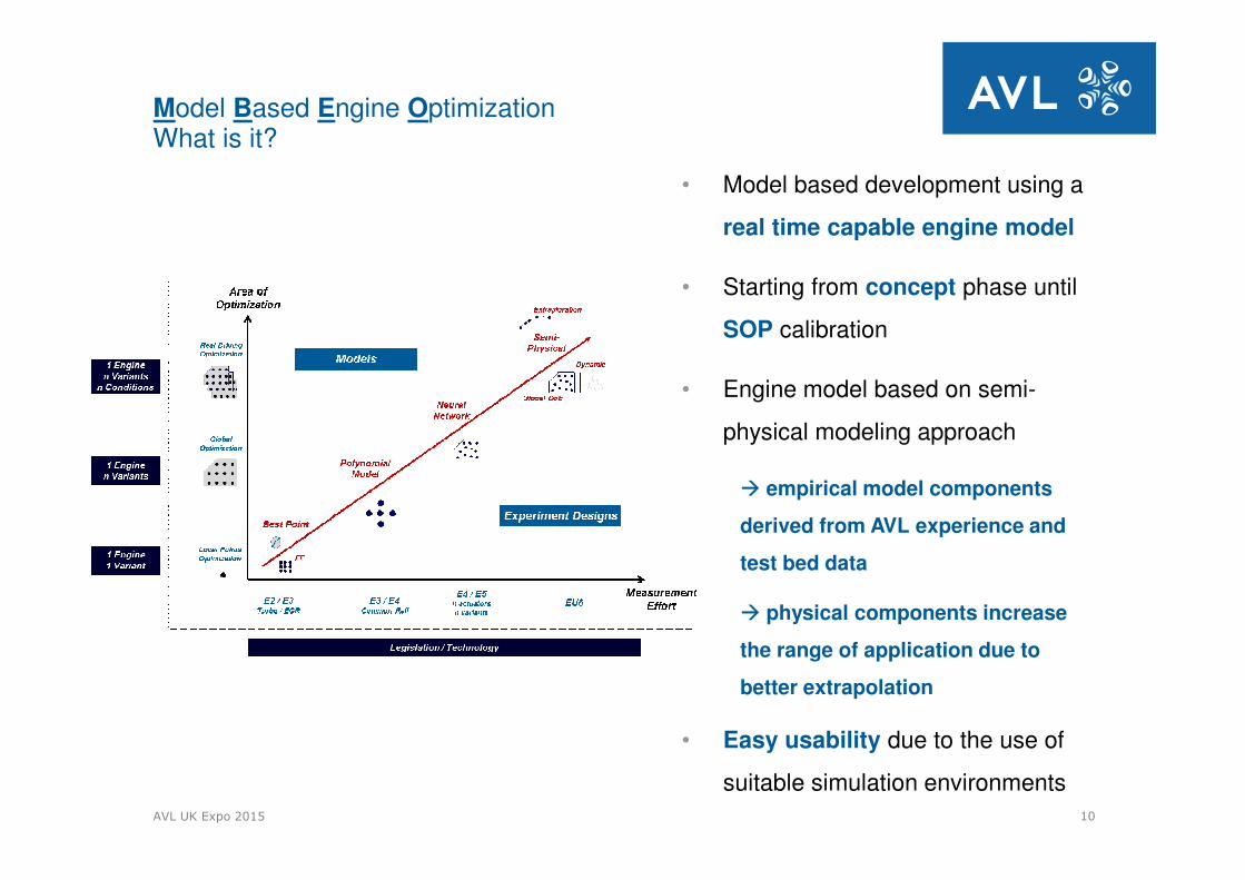
• Model based development using a
real time capable engine model
• Starting from concept phase until
SOP calibration
• Engine model based on semi-
physical modeling approach
� empirical model components
derived from AVL experience and
test bed data
� physical components increase
the range of application due to
better extrapolation
• Easy usability due to the use of
suitable simulation environments
Model Based Engine OptimizationWhat is it?

11
Model Based Development -MoBEOModelling Approach
Te
stb
ed
resu
lts
EAS System (DOC,
Semi-physical
Thermodynamic
NOx-Emission
EAS System (DOC, DPF, SCR, NLT)
Empirical
static global
HC, CO, Soot, SPL,…
Cameo M&M
Empirical
static global
HC, CO, Soot, SPL,…
Cameo M&M
DoE MeasurementsPuma / Cameo
T&M
DoE MeasurementsPuma / Cameo
T&M
Combined-model
Increased number of engine specific outputs
Combined-model
Increased number of engine specific outputs
HiL SetupHiL Setup
MiLSetupfOXCal
MiLSetupfOXCal
Baseengine testbeddevelopment
Puma / Cameo T&M
Baseengine testbeddevelopment
Puma / Cameo T&M
Baseengine testbeddevelopment
Puma / Cameo T&M
Emission validationEmission validation
Environmental validationEnvironmental validation
Modelrefinement
Pre
-ca
libra
tio
n
Do
E T
est R
esu
lts
Fie
ld d
ata
Robustness analysis
Pre
-ca
libra
tio
n
First engineRun
Puma / Cameo T&M
First engineRun
Puma / Cameo T&M
Basic model setup
MoBEO
Basic model setup
MoBEO
refined model setup
MoBEO
Semi-physical
Basic Model without
measurement data
Virtual
RealPost-
ProcessingPost-
ProcessingAdvanced Test
AutomationAdvanced Test
AutomationExtension to the
Virtual EnvironmentsExtension to the
Virtual Environments
Model-based calibration of various variants
Variant specific hardware change(e.g. intake piping, …)(No combustion HW change)

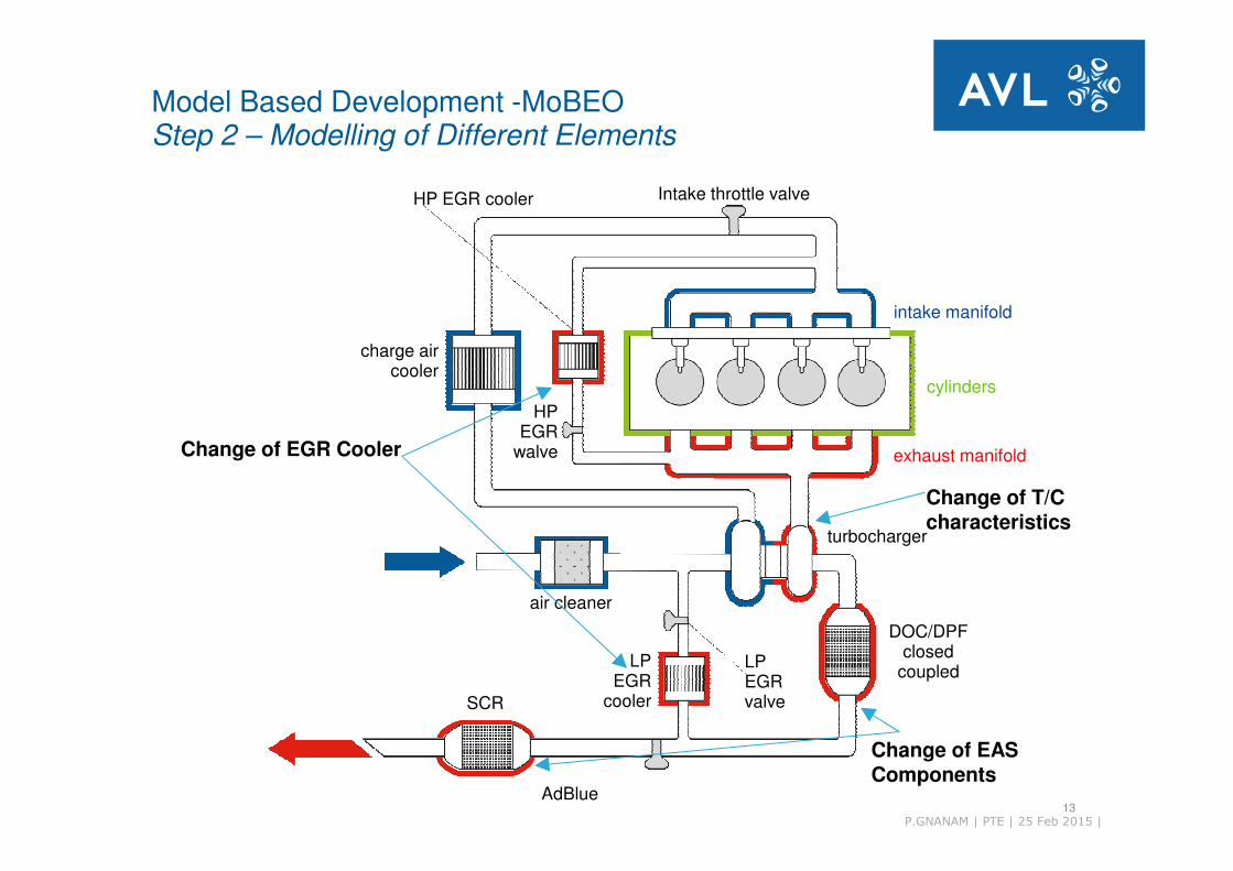
AVL UK Expo 2015 12AdBlue
SCR
LPEGR
cooler
DOC/DPFclosed
coupled
turbocharger
exhaust manifold
intake manifold
cylinders
air cleaner
HPEGR
walve
charge aircooler
HP EGR cooler Intake throttle valve
LPEGRvalve
Engine Model combined with EAS Model – Modular combined Semi-
physical models withhigh flexibility
Model Based Development -MoBEOStep 1 – Modeling EU6 Base Engine
13P.GNANAM | PTE | 25 Feb 2015 |
AdBlue
SCR
LPEGR
cooler
DOC/DPFclosed
coupled
turbocharger
exhaust manifold
intake manifold
cylinders
air cleaner
HPEGR
walve
charge aircooler
HP EGR cooler Intake throttle valve
LPEGRvalve
Change of EGR Cooler
Change of T/C characteristics
Change of EAS Components
Model Based Development -MoBEOStep 2 – Modelling of Different Elements

AVL UK Expo 2015 14
Concept / Layout
Start
of
Production
Endurance testing
Development ProcessConsequent usage of real-time system simulation
Modelquality
AVL data base,
measurements of
single components
Component
and system
developmentCalibration / Validation
Data vehicle testing
Data engine test bed
Consequent usage of real-time system simulation

AVL UK Expo 2015 15
MOBEOApplication environment
AVL UK Expo 2015 16
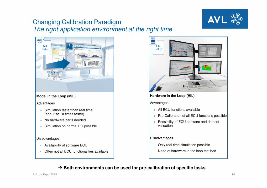
HiL Setup
MiLSetup
Model in the Loop (MiL)
Advantages
+ Simulation faster than real time (app. 5 to 10 times faster)
+ No hardware parts needed
+ Simulation on normal PC possible
Disadvantages
- Availability of software ECU
- Often not all ECU functionalities available
Hardware in the Loop (HiL)
Advantages
+ All ECU functions available
+ Pre-Calibration of all ECU functions possible
+ Possibility of ECU software and dataset validation
Disadvantages
- Only real time simulation possible
- Need of hardware in the loop test bed
� Both environments can be used for pre-calibration of specific tasks
Changing Calibration ParadigmThe right application environment at the right time
AVL UK Expo 2015 17
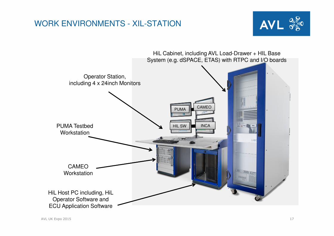
PUMA TestbedWorkstation
CAMEO Workstation
HiL Host PC including, HiL Operator Software and
ECU Application Software
PUMACAMEO
HIL SW INCA
Operator Station,including 4 x 24inch Monitors
HiL Cabinet, including AVL Load-Drawer + HIL Base System (e.g. dSPACE, ETAS) with RTPC and I/O boards
WORK ENVIRONMENTS - XIL-STATION
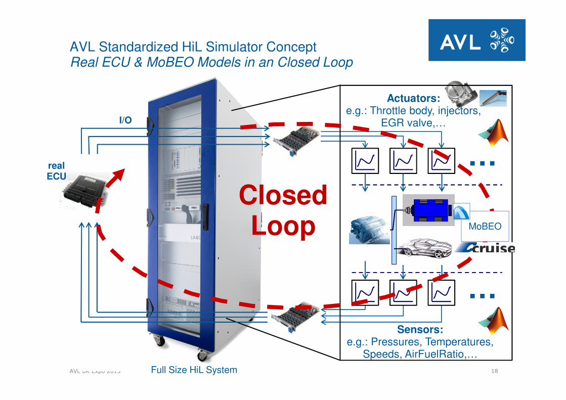
AVL UK Expo 2015 18Full Size HiL System
AVL Standardized HiL Simulator ConceptReal ECU & MoBEO Models in an Closed Loop
realECU
Actuators:e.g.: Throttle body, injectors,
EGR valve,…
…
Sensors:e.g.: Pressures, Temperatures,
Speeds, AirFuelRatio,…
…
I/O
ClosedLoop MoBEO
AVL UK Expo 2015 19
MOBEOModel accuracy
AVL UK Expo 2015 20
To
rqu
e [
Nm
]
0
50
100
150
200
Sp
eed
[rp
m]
500
1100
1700
2300
2900
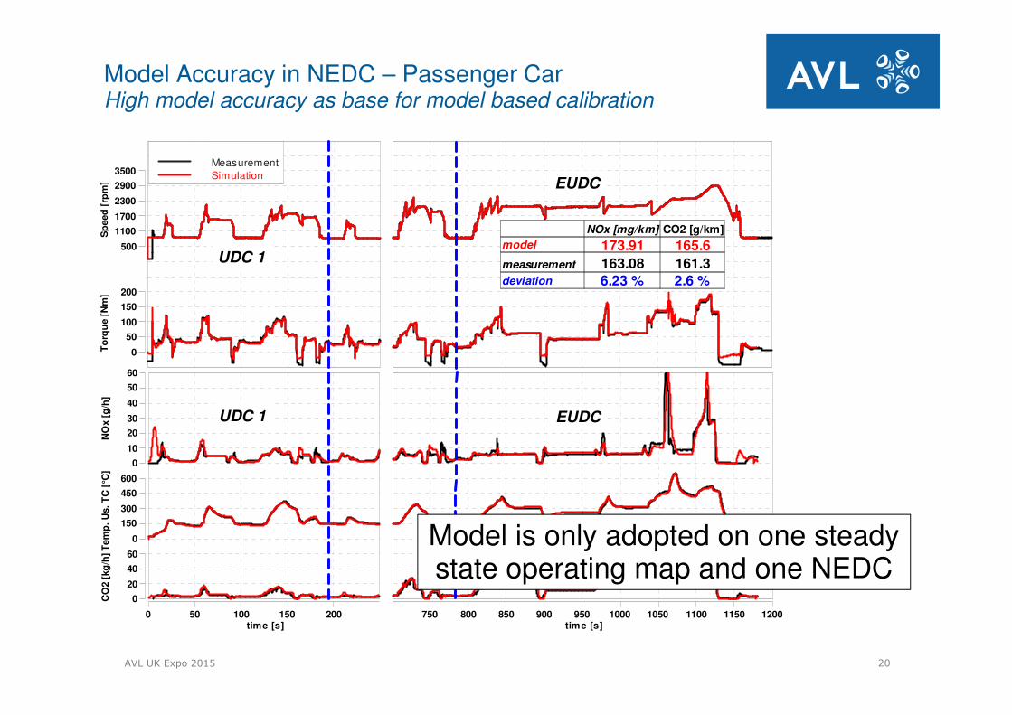
3500MeasurementSimulation
EUDC
UDC 1
0 50 100 150 200time [s]
Tem
p. U
s. T
C [
°C]
0
150
300
450
600
NO
x [
g/h
]
0
10
20
30
40
50
60
CO
2 [
kg
/h]
0
20
40
60
UDC 1
750 800 850 900 950 1000 1050 1100 1150 1200time [s]
EUDC
NOx [mg/km] CO2 [g/km]
model 173.91 165.6
measurement 163.08 161.3deviation 6.23 % 2.6 %
Model is only adopted on one steadystate operating map and one NEDC
Model Accuracy in NEDC – Passenger CarHigh model accuracy as base for model based calibration
AVL UK Expo 2015 21
Sp
eed
[rp
m]
500
1000
1500
2000
2500
3000
To
rqu
e [
Nm
]
0
50
100
150
200
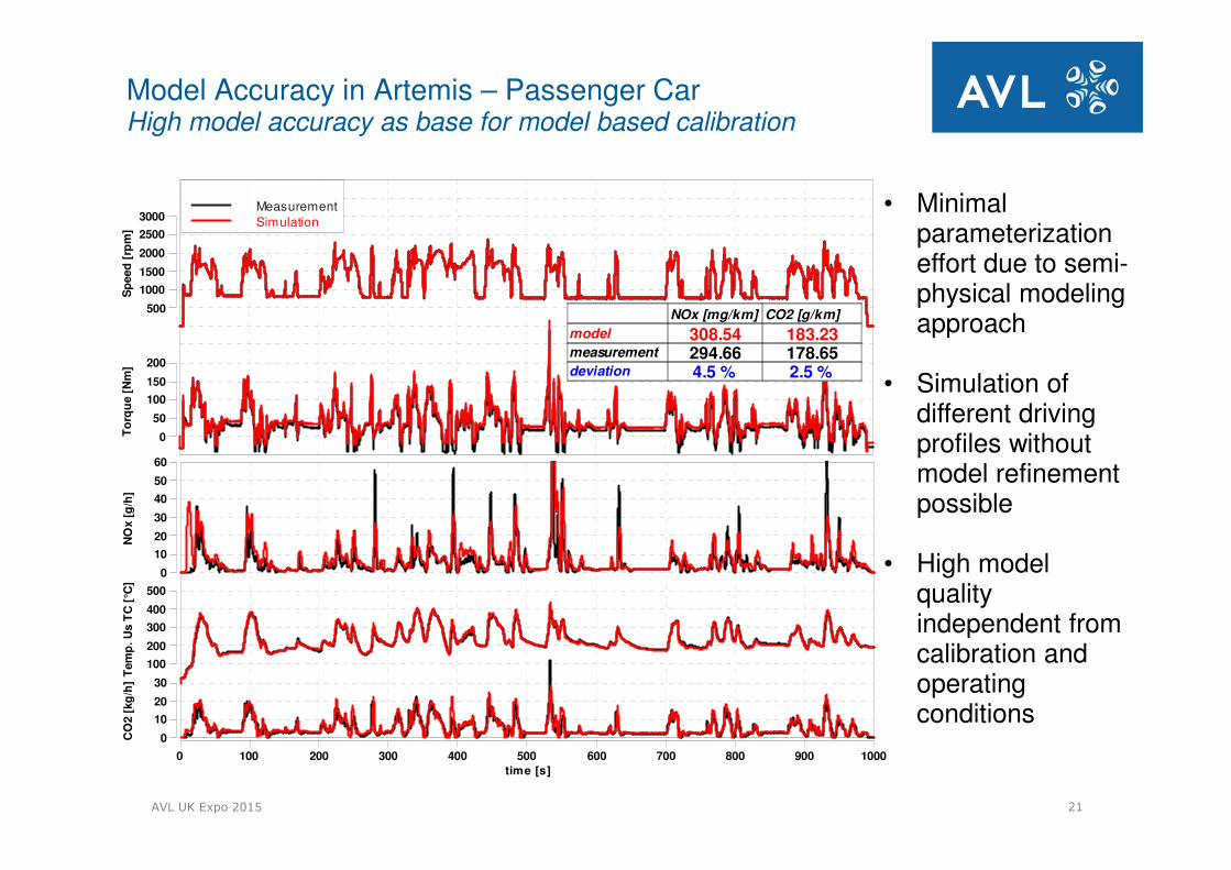
MeasurementSimulation
0 100 200 300 400 500 600 700 800 900 1000
time [s]
Tem
p. U
s T
C [
°C]
100
200
300
400
500
NO
x [
g/h
]
0
10
20
30
40
50
60
CO
2 [
kg
/h]
0
10
20
30
NOx [mg/km] CO2 [g/km]
model 308.54 183.23measurement 294.66 178.65deviation 4.5 % 2.5 %
• Minimal parameterization effort due to semi-physical modeling approach
• Simulation of different driving profiles without model refinement possible
• High model quality independent from calibration and operating conditions
Model Accuracy in Artemis – Passenger CarHigh model accuracy as base for model based calibration
AVL UK Expo 2015 22
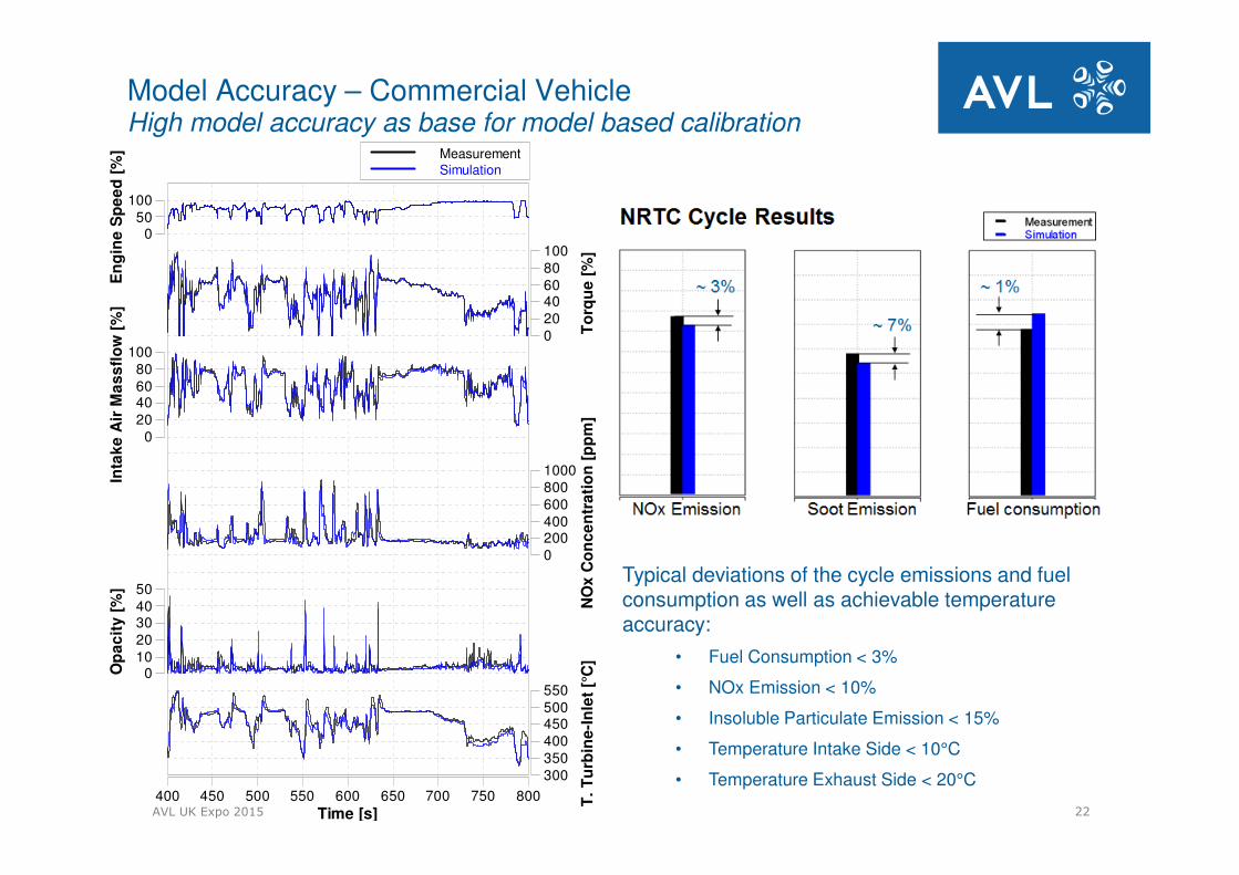
Model Accuracy – Commercial VehicleHigh model accuracy as base for model based calibration
Typical deviations of the cycle emissions and fuel consumption as well as achievable temperature accuracy:
• Fuel Consumption < 3%
• NOx Emission < 10%
• Insoluble Particulate Emission < 15%
• Temperature Intake Side < 10°C
• Temperature Exhaust Side < 20°C400 450 500 550 600 650 700 750 800
Time [s]
T.
Tu
rbin
e-I
nle
t [°
C]
300350400450500550
NO
x C
on
ce
ntr
ati
on
[p
pm
]
02004006008001000
Op
ac
ity
[%
]
01020304050
En
gin
e S
pe
ed
[%
]
050
100
To
rqu
e [
%]
020406080100
Inta
ke
Air
Ma
ss
flo
w [
%]
020406080
100
MeasurementSimulation

AVL UK Expo 2015 23
MODEL BASED DEVELOPMENTUse - Cases

AVL UK Expo 2015 24
Model Based Development Concept Investigations
Model based concept investigations
� Assessment of technology route
� Simulation of transient behaviour of engine in early concept phase on MiLenvironment
� Definition of possible concepts considering the interaction between
� engine
� exhaust aftertreatment system
� software and calibration
� Sensors and actuators
� environmental conditions
Vehicle & drivetrain simulation

AVL UK Expo 2015 25
Powertrain Calibration tasks for MiL/HiL:
� RDE – Real Driving Emission evaluation
� EAS Simulation
� Calibration for non-standard ambient conditions
� Calibration of component protection
� In-Use Compliance - PEMS
� Sensitivity studies taking into account system interactions
� OBD – Diagnoses, IUPR
� Software and dataset validation
HW Testing & Calibration
Virtual Testing & Calibration
engine & EATS modeling
Model Based Development Powertrain Use cases
AVL UK Expo 2015 26
700
800
900
1000
1100
1200
1300
1400
1500
1600
1700
1800
1900
2000
Engine Speed [1/min]
Tem
p. u
pstr
.Tu
rbin
e [
°C]
0
200
400
600
800
Pre
ssu
re u
pstr
. T
urb
ine [
kP
a]
0
125
250
375
500
LP
TC
Sp
eed
[rp
m]
0
50000
100000
HP
TC
Sp
eed
[rp
m]
50000
75000
100000
125000
150000
Tem
p. d
s. C
om
pre
sso
r [°
C]
0
100
200
BM
EP
[kP
a]
800
1600
2400
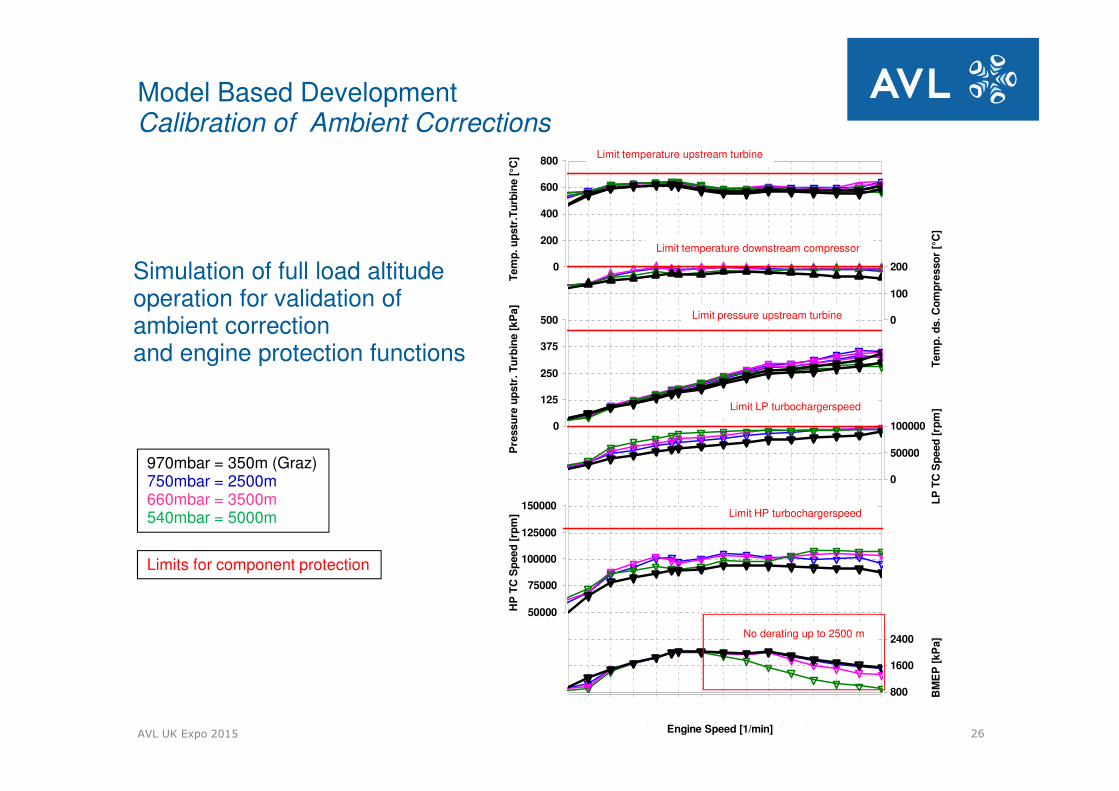
Model Based DevelopmentCalibration of Ambient Corrections
Simulation of full load altitude operation for validation of ambient correction and engine protection functions
970mbar = 350m (Graz)750mbar = 2500m660mbar = 3500m540mbar = 5000m
Limits for component protection
Limit temperature upstream turbine
Limit temperature downstream compressor
Limit pressure upstream turbine
Limit LP turbochargerspeed
Limit HP turbochargerspeed
No derating up to 2500 m
AVL UK Expo 2015 27
700
800
900
1000
1100
1200
1300
1400
1500
1600
1700
1800
1900
2000
Engine Speed [1/min]
Tem
p. u
ps
tr.T
urb
ine [
°C]
0
200
400
600
800
Pre
ss
ure
up
str
. T
urb
ine [
kP
a]
0
125
250
375
500
LP
TC
Sp
eed
[rp
m]
0
50000
100000
HP
TC
Sp
eed
[rp
m]
50000
75000
100000
125000
150000
Tem
p. d
s. C
om
pre
sso
r [°
C]
0
100
200
BM
EP
[kP
a]
800
1600
2400
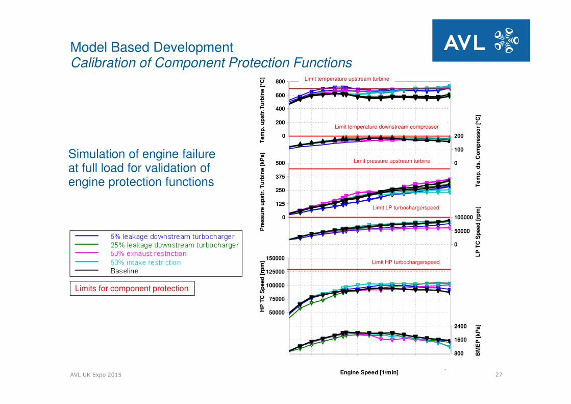
Model Based Development Calibration of Component Protection Functions
Simulation of engine failure at full load for validation of engine protection functions
Limit temperature upstream turbine
Limit temperature downstream compressor
Limit pressure upstream turbine
Limit LP turbochargerspeed
Limit HP turbochargerspeed
Limits for component protection
AVL UK Expo 2015 28
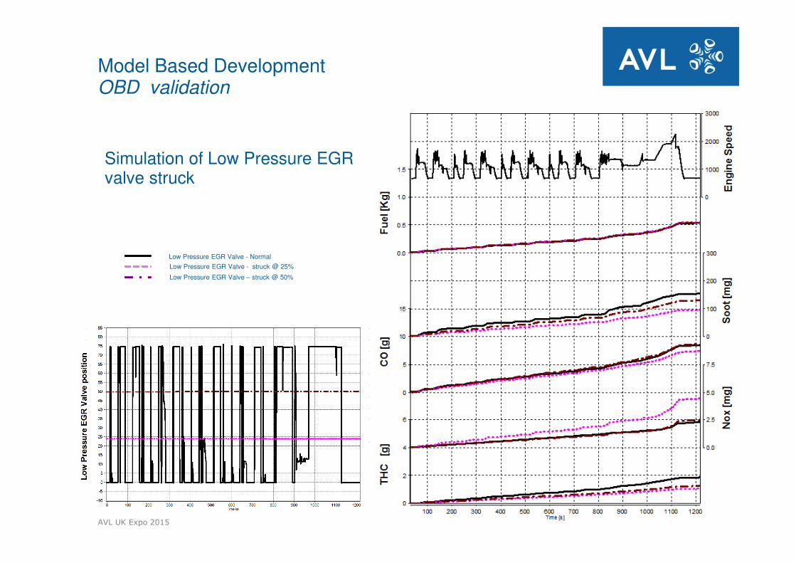
Model Based Development OBD validation
Low Pressure EGR Valve - Normal
Low Pressure EGR Valve - struck @ 25%
Low Pressure EGR Valve – struck @ 50%
Simulation of Low Pressure EGR valve struck
AVL UK Expo 2015 29
Calibration
Driving Cycle
Environment
Production Tolerances Aging Effects
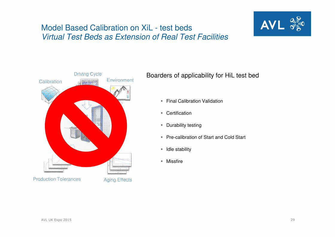
Boarders of applicability for HiL test bed
� Final Calibration Validation
� Certification
� Durability testing
� Pre-calibration of Start and Cold Start
� Idle stability
� Missfire
Model Based Calibration on XiL - test beds Virtual Test Beds as Extension of Real Test Facilities
AVL UK Expo 2015 30
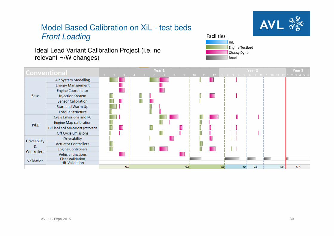
FacilitiesHiL
Engine Testbed
Chassy Dyno
Road
Ideal Lead Variant Calibration Project (i.e. norelevant H/W changes)
Model Based Calibration on XiL - test beds Front Loading
AVL UK Expo 2015 31
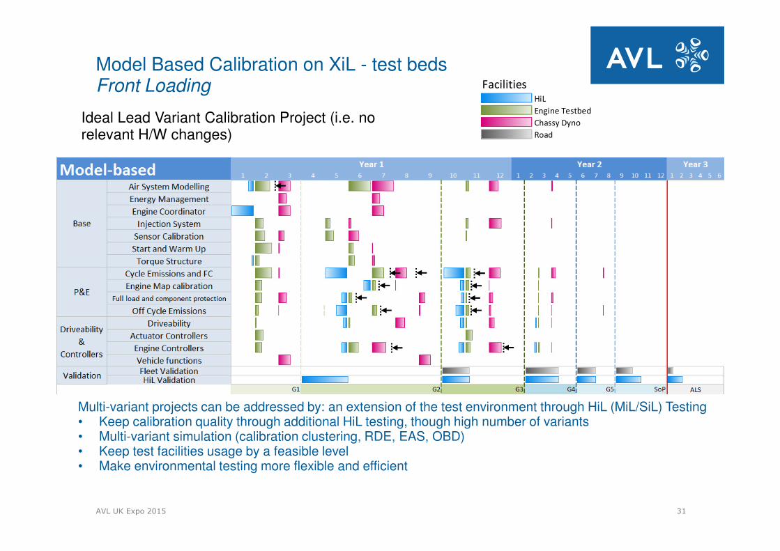
FacilitiesHiL
Engine Testbed
Chassy Dyno
Road
Ideal Lead Variant Calibration Project (i.e. no relevant H/W changes)
Multi-variant projects can be addressed by: an extension of the test environment through HiL (MiL/SiL) Testing• Keep calibration quality through additional HiL testing, though high number of variants• Multi-variant simulation (calibration clustering, RDE, EAS, OBD)• Keep test facilities usage by a feasible level• Make environmental testing more flexible and efficient
Model Based Calibration on XiL - test beds Front Loading
AVL UK Expo 2015 32
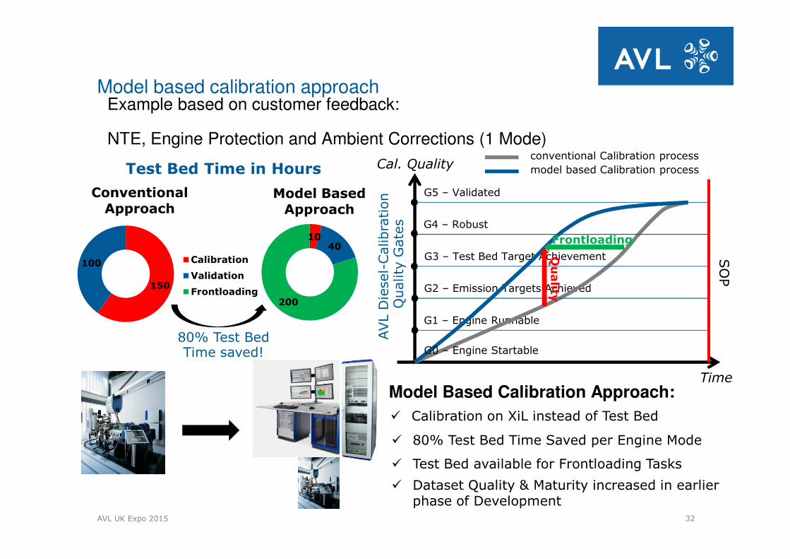
1040
200
Model Based Approach
150
100
Conventional Approach
Calibration
Validation
Frontloading
Model based calibration approach
Model Based Calibration Approach:
Example based on customer feedback:
NTE, Engine Protection and Ambient Corrections (1 Mode)
80% Test Bed Time saved!
Test Bed Time in Hours
SO
P
AVL D
iesel-
Calibra
tion
Quality
Gate
s
Time
Cal. Quality
G1 – Engine Runnable
G2 – Emission Targets Achieved
G3 – Test Bed Target Achievement
G5 – Validated
G4 – Robust
conventional Calibration process
model based Calibration process
G0 – Engine Startable
� Calibration on XiL instead of Test Bed
� 80% Test Bed Time Saved per Engine Mode
� Test Bed available for Frontloading Tasks
� Dataset Quality & Maturity increased in earlier phase of Development
FrontloadingQ
uality
AVL UK Expo 2015 33
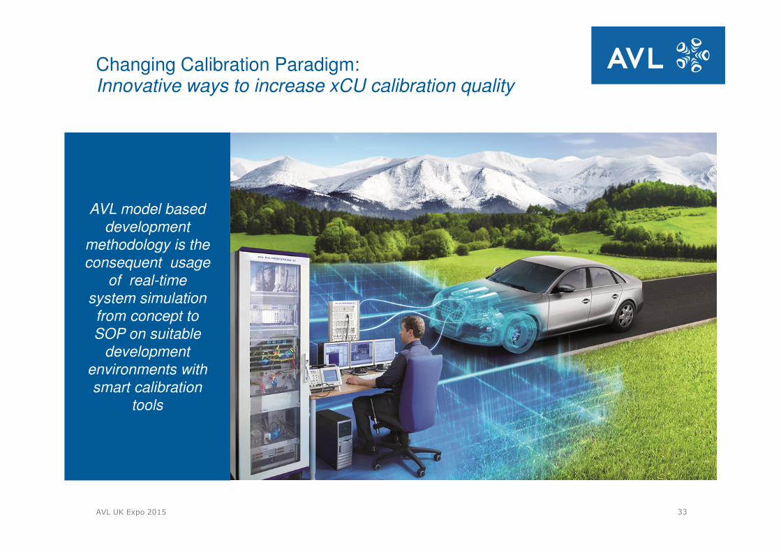
Changing Calibration Paradigm:Innovative ways to increase xCU calibration quality
AVL model based
development
methodology is the
consequent usage
of real-time
system simulation
from concept to
SOP on suitable
development
environments with
smart calibration
tools