model cv 3171 - goulds pumps cv 3171 iom 05/11 3 forword this manual provides instructions for the...
TRANSCRIPT
1 CV 3171 IOM 05/11
Installation, Operation and Maintenance Instructions
Model CV 3171
2 CV 3171 IOM 05/11
Pump Safety Tips
Safety Apparel: • Insulated work gloves when handling hot
bearings or using a bearing heater • Heavy work gloves when handling parts with
sharp edges, especially impellers • Safety glasses (with side shields) for eye
protection, especially in machine shop areas • Steel-toed shoes for foot protection when
handling parts, heavy tools, etc. • Other personal protective equipment to protect
against hazard/toxic fluids Coupling Guards: • Never operate a pump without a coupling guard
properly installed Flanged Connections: • Never force piping to make a connection with a
pump • Use only fasteners of the proper size and
material
• Ensure there are no missing fasteners • Beware of corroded or loose fasteners. Operation: • Do not operate below minimum rated flow, or
with suction/discharge valves closed • Do not open vent or drain valves, or remove
plugs while system is pressurized Maintenance Safety: • Always lockout power • Ensure pump is isolated from system and
pressure is relieved before disassembling pump, removing plugs, or disconnecting piping
• Use proper lifting and supporting equipment to
prevent serious injury • Observe proper decontamination procedures • Know and follow company safety regulations Observe all cautions and warnings highlighted in pump Installation, Operation and Maintenance Instructions.
CV 3171 IOM 05/11 3
FORWORD This manual provides instructions for the Installation, Operation, and Maintenance of the Goulds Model CV3171 Vertical Vortex (recessed impeller) as well as the low flow sizes. This manual covers the standard product plus common options that are available. For special options, supplemental instructions are supplied. This manual must be read and understood before installation and start-up. The design, materials and workmanship incorporated in the construction of a Goulds pump makes them capable of giving long, trouble-free service. The life and satisfactory service of any mechanical unit, however, is enhanced and extended by correct application, proper installation, periodic inspection, condition monitoring and careful maintenance. This instruction manual was prepared to assist operators in understanding the construction and the correct methods of installing, operating, and maintaining these pumps. ITT Goulds Pumps shall not be liable for physical injury, damage or delays caused by a failure to observe the instructions for installation, operation, and maintenance contained in this manual. Warranty is valid only when genuine ITT Goulds parts are used. Use of the equipment on a service other than stated in the order will nullify the warranty, unless written approval is obtained in advance from ITT Goulds Pumps. Supervision by an authorized ITT Goulds representative is recommended to assure proper installation. Additional manuals can be obtained by contacting your local ITT Goulds representative or by calling 1-800-446-8537.
THIS MANUAL EXPLAINS
Proper Installation Start-up Procedures Operation Procedures Routine Maintenance Pump Overhaul Troubleshooting Order Spare or Repair Parts
4 CV 3171 IOM 05/11
When a pumping unit is installed in a potentially explosive atmosphere, the instructions after the Ex symbol must be followed. Personal injury and/or equipment damage may occur if these instructions are not followed. If there is any question regarding these requirements or if the
equipment is to be modified, please contact a Goulds representative before proceeding.
Explosion Prevention
In order to reduce the possibility of accidental explosions in atmospheres containing explosive gasses and/or dust, the instructions under the ATEX symbol must be closely followed. ATEX certification is a directive enforced in Europe for non-electrical and electrical equipment installed in Europe. ATEX requirements are not restricted to Europe, and are useful guidelines
for equipment installed in any potentially explosive environment.
Special ATEX Considerations
All installation and operation instructions in this manual must be strictly adhered to. In addition, care must be taken to ensure that the equipment is properly maintained. This includes but is not limited to:
• monitoring the pump frame and liquid end temperature • maintining proper bearing lubrication • ensuring that the pump is operated in the intended hydraulic range
ATEX Identification
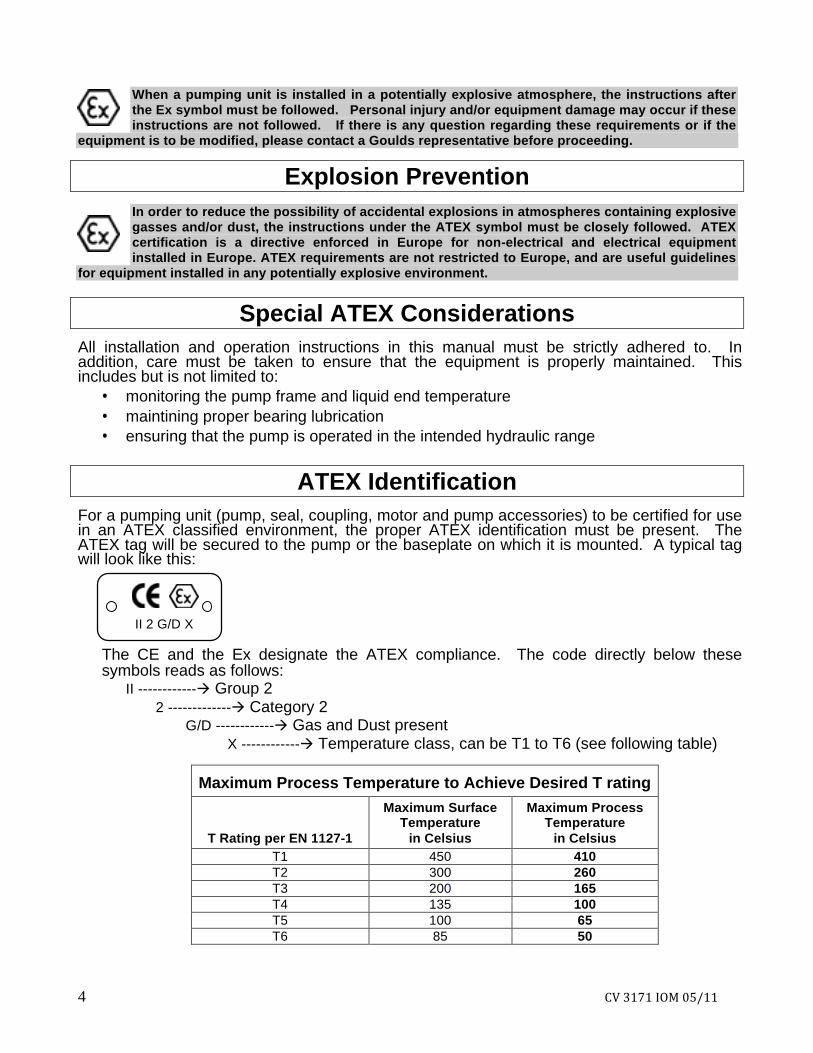
For a pumping unit (pump, seal, coupling, motor and pump accessories) to be certified for use in an ATEX classified environment, the proper ATEX identification must be present. The ATEX tag will be secured to the pump or the baseplate on which it is mounted. A typical tag will look like this:
II 2 G/D X The CE and the Ex designate the ATEX compliance. The code directly below these symbols reads as follows:
II ------------ Group 2 2 ------------- Category 2
G/D ------------ Gas and Dust present X ------------ Temperature class, can be T1 to T6 (see following table)
Maximum Process Temperature to Achieve Desired T rating
T Rating per EN 1127-1
Maximum Surface Temperature
in Celsius
Maximum Process Temperature
in Celsius T1 450 410 T2 300 260 T3 200 165 T4 135 100 T5 100 65 T6 85 50
CV 3171 IOM 05/11 5
The code classification marked on the equipment should be in accordance with the specified area where the equipment will be installed. If it is not, please contact your ITT Goulds representative before proceeding.
Intended Use The ATEX conformance is only applicable when the pump unit is operated within its intended use. All instructions within this manual must be followed at all times. Operating, installing or maintaining the pump unit in any way that is not covered in this manual can cause serious personal injury or damage to the equipment. This includes any modification to the equipment or use of parts not provided by ITT Goulds. If there is any question regarding the intended use of the equipment please contact an ITT Goulds representative before proceeding.

6 CV 3171 IOM 05/11
THIS PAGE INTENTIONALLY LEFT BLANK
CV 3171 IOM 05/11 7
TABLE OF CONTENTS PAGE SECTION 9 SAFETY 1 11 GENERAL INFORMATION 2 15 INSTALLATION 3 21 OPERATION 4 25 PREVENTIVE MAINTENANCE 5 33 DISASSEMBLY AND REASSEMBLY 6 47 APPENDICIES 7 51 SPARE PARTS 8

8 CV 3171 IOM 05/11
THIS PAGE INTENTIONALLY LEFT BLANK

CV 3171 IOM 05/11 9
SAFETY DEFINITIONS ........................................................................................................................... 7 GENERAL PRECAUTIONS ..................................................................................................... 7
DEFINITIONS This pump has been designed for safe and reliable operation when properly used and maintained in accordance with instructions contained in this manual. A pump is a pressure containing device with rotating parts that can be hazardous. Operators and maintenance personnel must realize this and follow safety measures. ITT Goulds Pumps shall not be liable for physical injury, damage or delays caused by a failure to observe the instructions in this manual. Throughout this manual the words WARNING, CAUTION, and NOTE are used to indicate procedures or situations which require special operator attention:
WARNING Operating procedure, practice, etc. which, if not correctly followed, could result in personal injury or loss of life.
CAUTION Operating procedure, practice, etc. which, if not followed could result in damage or destruction of equipment.
NOTE: Operating procedure, condition, etc. which is essential to observe. EXAMPLES
WARNING Pump shall never be operated without coupling guard installed correctly.
CAUTION Throttling flow from the suction side may cause cavitation and pump damage.
NOTE: Proper alignment is essential for long pump life.
GENERAL PRECAUTIONS Personal injury will result if procedures outlined in this manual are not followed.
Never run pump below recom- mended minimum flow or when dry.
Never apply heat to remove impeller. It may explode due to trapped liquid.
Always lock out power to the driver before performing pump maintenance.
Never use heat to disassemble pump due to risk of explosion from trapped liquid.
Never operate pump without safety devices installed.
Never operate pump without coupling guard correctly installed.
Never operate pump with discharge valve closed.
Never operate pump beyond the rated conditions to which the pump was sold.
Never operate pump with suction valve closed.
Never start pump without proper prime, or proper liquid level in self priming pumps.
Do not change conditions of service without approval of an authorized Goulds representative.
1
10 CV 3171 IOM 05/11
Condition Monitoring For additional safety precautions, and where noted in this manual, condition monitoring devices should be used.
This includes, but is not limited to: Pressure gauges Flow meters Level indicators Motor load readings Temperature detectors Bearing monitors Leak detectors PumpSmart control system
For assistance in selecting the proper instrumentation and its use, please contact your ITT Goulds representative.
1
1
CV 3171 IOM 05/11 11
GENERAL INFORMATION PUMP DESCRIPTION ............................................................................................................9 NAMEPLATE INFORMATION..............................................................................................10 RECEIVING THE PUMP.......................................................................................................11 Storage Requirements ...............................................................................................11 Handling .....................................................................................................................11 Uncrating/Deskidding .................................................................................................12
PUMP DESCRIPTION The model CV3171 is a vertical vortex, recessed open impeller pump that generates pressure head by creating a vortex in the casing. Use of a recessed impeller allows for solids, entrained air, or shear sensitive liquid handling. The model is based on 1 power end and 8 hydraulic pump sizes: 2X2-8 2X2-10 3X3-10 2X3-13 3X4-13 LF 1x1.5-8 LF 1x2-10 LF 1.5x3-13 Casing: The casing of the CV3171 is concentric volute and available with optional connections for venting, flushing and solids clean out. Impeller: The impeller of the CV3171 is fully open, has curved vanes, and is threaded to the shaft. The LF sizes have straight radial vanes and are threaded to the shaft. The threads are sealed from the pumpage by a Teflon O-ring. Strainer: The strainer is a basket type with openings sized to prevent the entrance of large solids commonly ending up in open sumps. Power End: The power end of this pump is identical to the 3171 power end. It consists of the motor, coupling, motor mount, support plate, double-row ball thrust bearing, shaft, column pipe header, steady bearings, and column pipe extension.
Bearings: The thrust bearing is a grease or oil-mist lubricated double row angular contact ball bearing. It is shouldered and locked to the shaft and the housing enabling it to carry all of the thrust loads and some of the radial load. All fits are precision machined to industry standards. The steady bearings are press fit sleeve bearings. Fits are designed for optimum life under all operating conditions. Seals: The standard CV3171 has three seals. An upper labyrinth seal is used to exclude dirt
and water from the thrust bearing. A lower grease seal is used below the thrust
bearing to contain the grease and exclude any possible contamination.
A carbon Teflon casing collar is installed
immediately behind the impeller in the adapter to minimize recirculation back to the sump, thereby maximizing hydraulic efficiency.
Discharge Elbow: The discharge elbow is a short radius elbow that provides compact size and minimum profile. Direction of Rotation: Clockwise (right hand) as viewed from the driver, looking at the pump shaft. Maximum Solids Size: For CV3171 pumps, the max. solids size is 1.875 in. for 2” discharge and 2.875 in. for 3” discharge. Refer to the current pump curve for maximum solids capabilities.
2
12 CV 3171 IOM 05/11
Steady Bearings: 1. Carbon and Carbon Filled Teflon - These
bearings are chemically inert in most liquids and can be used in liquids up to the temperature limits of the pump. They should not be used in liquids containing abrasive solids. Clear flush from the support plate is required.
2. Fluted Rubber or Viton - These bearings
consist of fluted rubber or Viton contained within a metal shell. Clear water from an outside source, 1 to 2 GPM, is required to each bearing housing. They are ideally suited for liquids containing abrasive solids but are limited to 160°F temperature liquid. Corrosion resistant shafting is required.
3. Metallic Bearing - Bronze steady bearings are available and must be grease lubricated. Lack of lubrication can lead to galling and eventual seizing. It becomes extremely difficult to keep enough grease in the housing when handling hot liquids, caustic solutions or solvents. Unless an adequate maintenance program exists, it is recommended that a self-lubricating bearing such as carbon be used in place of the metallic bearing.
4. Sealed Bearings - Recommended for abrasive
liquids where no outside flush is available. The carbon bearing is sealed within the housing by two lip seals and filled by grease via pressure lubricator located above the support plate. The pressure cup must be kept full of grease. The control screw on the pressure cup should be wide open to start and then controlled by usage.
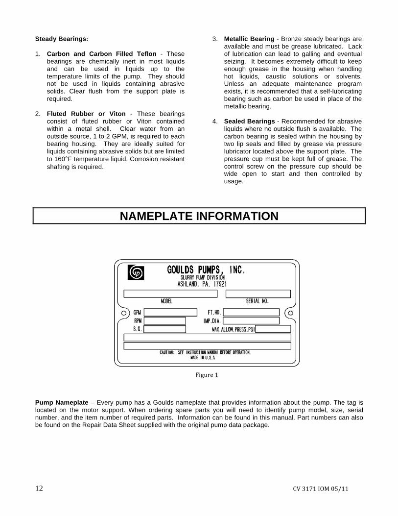
NAMEPLATE INFORMATION
Pump Nameplate – Every pump has a Goulds nameplate that provides information about the pump. The tag is located on the motor support. When ordering spare parts you will need to identify pump model, size, serial number, and the item number of required parts. Information can be found in this manual. Part numbers can also be found on the Repair Data Sheet supplied with the original pump data package.
Figure 1
CV 3171 IOM 05/11 13
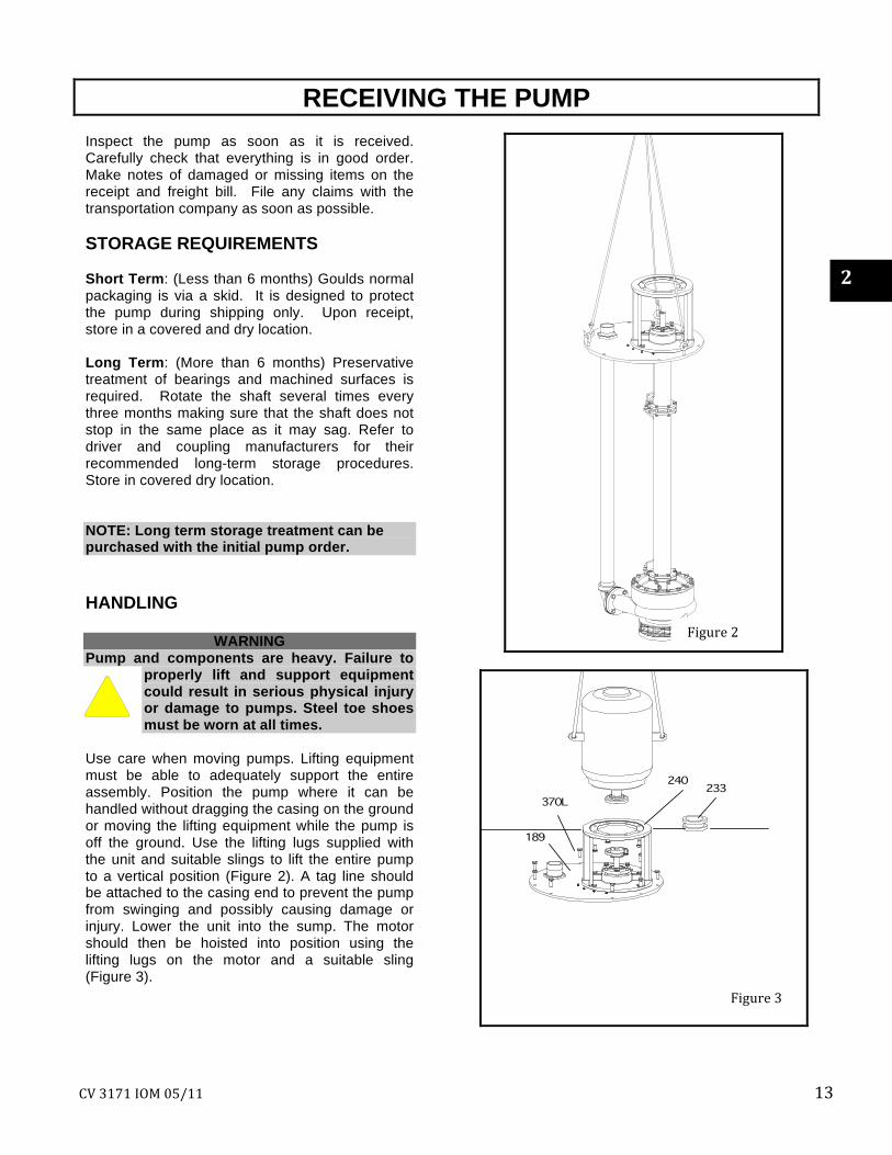
RECEIVING THE PUMP Inspect the pump as soon as it is received. Carefully check that everything is in good order. Make notes of damaged or missing items on the receipt and freight bill. File any claims with the transportation company as soon as possible. STORAGE REQUIREMENTS Short Term: (Less than 6 months) Goulds normal packaging is via a skid. It is designed to protect the pump during shipping only. Upon receipt, store in a covered and dry location. Long Term: (More than 6 months) Preservative treatment of bearings and machined surfaces is required. Rotate the shaft several times every three months making sure that the shaft does not stop in the same place as it may sag. Refer to driver and coupling manufacturers for their recommended long-term storage procedures. Store in covered dry location. NOTE: Long term storage treatment can be purchased with the initial pump order. HANDLING
WARNING Pump and components are heavy. Failure to
properly lift and support equipment could result in serious physical injury or damage to pumps. Steel toe shoes must be worn at all times.
Use care when moving pumps. Lifting equipment must be able to adequately support the entire assembly. Position the pump where it can be handled without dragging the casing on the ground or moving the lifting equipment while the pump is off the ground. Use the lifting lugs supplied with the unit and suitable slings to lift the entire pump to a vertical position (Figure 2). A tag line should be attached to the casing end to prevent the pump from swinging and possibly causing damage or injury. Lower the unit into the sump. The motor should then be hoisted into position using the lifting lugs on the motor and a suitable sling (Figure 3).
Figure 3
Figure 2
2
14 CV 3171 IOM 05/11
UNCRATING/DESKIDDING Care should be taken when uncrating or deskidding pumps. If shipment is not delivered in good order, and in accordance with the bill of
lading, note the damage or shortage on both the receipt and freight bill. Make any claims to the transportation company promptly. Instruction sheets as well as the instruction book for the pump are included in the shipment.
CV 3171 Installation and Operation Checklist
COMPLETE INITIAL DESCRIPTION SECTION NO. Installation Manual Received and Read ALL
Level Pit Opening 3
Level Support Plate 3
Check Motor Rotation ---CW ---CCW 3
Install Coupling 3
Rough Alignment Completed 3
Piping Installed and Alignment Rechecked 3
Flush or Grease Piping Connected 4
Impeller Clearance Set ______ Inch 4,5
Pump Shaft-Free Turning 4
Float Controls Understood 4
Bearing Types and Lubrication 4
Coupling Guard Installed 4
Discharge Valve Partially Open 4
CV 3171 IOM 05/11 15
INSTALLATION INSPECTION ......................................................................................................................... 15 SITE/FOUNDATION .............................................................................................................. 16 WHEN PIT COVER IS USED................................................................................................. 16 NO PIT COVER...................................................................................................................... 17 IMPELLER CLEARANCE SETTING..................................................................................... 17 MOTOR INSTALLATION AND COUPLING ALIGNMENT ................................................... 17 PIPING ................................................................................................................................... 19
INSPECTION
Equipment that will operate in a potentially explosive environment must be installed
in accordance with the following instructions.
All equipment being installed must be properly grounded to prevent unexpected static
electric discharge. If not, a static electric discharge may occur when the pump is drained and disassembled for maintenance purposes.
Service temperature in an ATEX classified environment is limited by Table 1 in the
ATEX identification section. 1. Remove all equipment from shipping
containers. 2. Completely clean the underside of the
support plate, and both sides of the optional pit cover (if supplied).
3. Remove any grease from machined
surfaces if applicable.
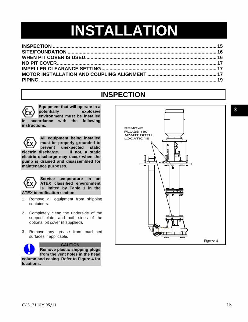
CAUTION Remove plastic shipping plugs from the vent holes in the head
column and casing. Refer to Figure 4 for locations.
3
Figure 4

16 CV 3171 IOM 05/11
SITE/FOUNDATION
The pump should be located where there is adequate space for installation, operation, maintenance, and inspection. Make sure there is adequate overhead clearance for installing and removing the pump. There should be at least 1/2” clearance between the sides of the pump and any portion of the pit. Vertical sump pumps are normally bolted to a concrete sump or steel tank. The supporting structure must provide a permanent rigid support
for the pumping unit(s) to eliminate any possible vibration. Support plates and/or pit covers are not normally grouted in place. The location and size of the mounting bolt holes are shown on the pump outline drawing provided with the pump data package. If anchor bolts are to be poured into the concrete, it is recommended that a sleeve type as shown in Figure 5 be used to allow for adjustment.
WHEN PIT COVER IS USED
If access to the bottom of the pit cover is not possible during the installation process, the pump (less motor), support plate and pit cover must be assembled and installed as a unit. 1. The pit cover must be installed level to insure
that the pump remains plumb when installed. 2. Carefully lower pit cover foundation bolts. 3. Using as long a level as practical, level the
pit cover in all directions with shims or wedges.
4. Hand tighten the anchor bolts, check the
level and re-shim if necessary. 5. Tighten all anchor bolts in a star pattern to
avoid distorting the support plate. 6. If access to the bottom side is possible,
carefully lower the pump and support plate onto the pit cover.
7. Install all bolts finger tight. 8. Check level on support plate and shim if
necessary.
9. Tighten all bolts in a star pattern to avoid distorting the support plate.
Vapor Proof Option The vapor proof option includes machined, gasketed fits between the support plate/pit cover and the pit cover/foundation. These gaskets must be installed to insure emissions performance. The pit cover should be bolted to a metal sole plate with a machined surface to insure an airtight seal.
Figure 5
Figure 5
CV 3171 IOM 05/11 17
NO PIT COVER Standard Support Plates 1. Carefully lower the pump and support plate onto
the foundation bolts. 2. Level the support plate in all directions using
shims and wedges. 3. Hand tighten the anchor bolts, check the level
and re-shim if necessary. 4. Tighten all anchor bolts in a star pattern to avoid
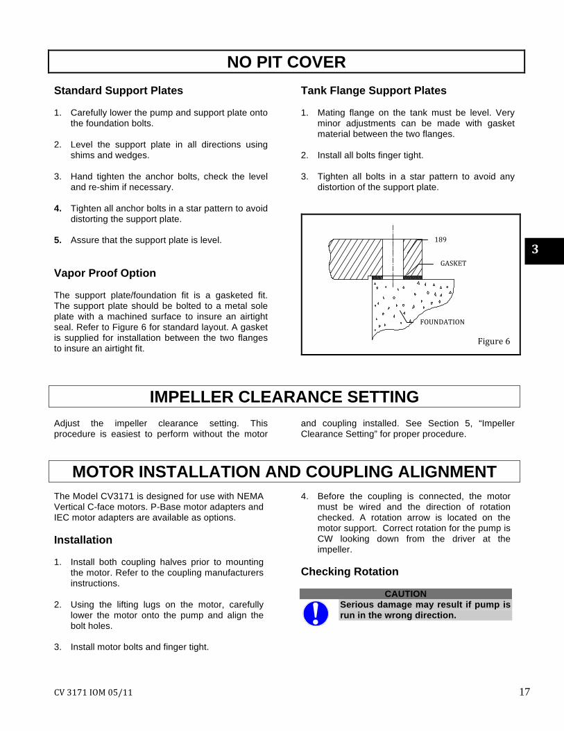
distorting the support plate. 5. Assure that the support plate is level. Vapor Proof Option The support plate/foundation fit is a gasketed fit. The support plate should be bolted to a metal sole plate with a machined surface to insure an airtight seal. Refer to Figure 6 for standard layout. A gasket is supplied for installation between the two flanges to insure an airtight fit.
Tank Flange Support Plates 1. Mating flange on the tank must be level. Very
minor adjustments can be made with gasket material between the two flanges.
2. Install all bolts finger tight. 3. Tighten all bolts in a star pattern to avoid any
distortion of the support plate.
IMPELLER CLEARANCE SETTING Adjust the impeller clearance setting. This procedure is easiest to perform without the motor
and coupling installed. See Section 5, “Impeller Clearance Setting” for proper procedure.
MOTOR INSTALLATION AND COUPLING ALIGNMENT
The Model CV3171 is designed for use with NEMA Vertical C-face motors. P-Base motor adapters and IEC motor adapters are available as options. Installation 1. Install both coupling halves prior to mounting
the motor. Refer to the coupling manufacturers instructions.
2. Using the lifting lugs on the motor, carefully
lower the motor onto the pump and align the bolt holes.
3. Install motor bolts and finger tight.
4. Before the coupling is connected, the motor must be wired and the direction of rotation checked. A rotation arrow is located on the motor support. Correct rotation for the pump is CW looking down from the driver at the impeller.
Checking Rotation
CAUTION Serious damage may result if pump is run in the wrong direction.
Figure 6
3
FOUNDATION
GASKET
189
18 CV 3171 IOM 05/11
WARNING Lock out power to prevent accidental start-up and physical injury.
1. Lock out power to driver. 2. Make sure coupling hubs are securely
fastened to shafts. 3. Ensure all persons and material are clear of
pump. 4. Unlock driver power. 5. Bump motor and observe rotation. Correct if
required. Alignment of Flexible Coupling
WARNING Before beginning any alignment procedure, make sure the driver power is locked out. Failure to lockout driver
power will result in serious physical injury. Alignment of the pump and motor is of extreme importance for trouble-free mechanical operation. Straight edge alignment by an experienced installer proves adequate for most installations. For disc couplings and applications where it is felt that alignment to tighter tolerances is desirable, use dial indicators. Standard dial indicator procedures would apply.
Alignment procedures must be followed to prevent unintended contact of rotating parts. Follow
coupling manufacturer’s installation and operation procedures.
When installing in a potentially explosive environment, ensure that the motor is properly certified.
The coupling used in an ATEX classified environment must be properly certified.
Straight Edge Alignment 1. Check for coupling alignment by laying a
straight edge across both coupling rims at four points 90 degree apart.
2. Move motor until straight edge rests evenly at
each position. Repeat procedure until correct alignment is achieved.
3. Install flexible sleeve between the hubs per the
manufacturer’s directions included with the pump data package.
4. Tighten all motor bolts. Coupling Guard
WARNING Never operate a pump without coupling guard properly installed. Personal injury will occur if pump is
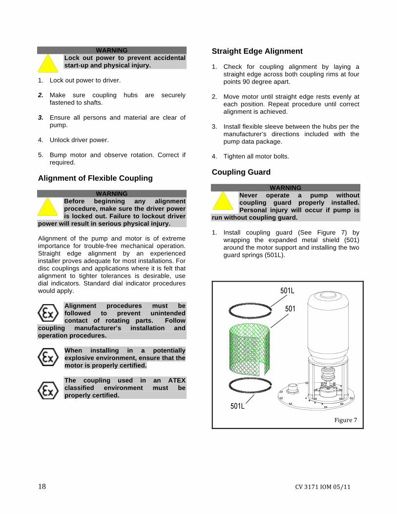
run without coupling guard. 1. Install coupling guard (See Figure 7) by
wrapping the expanded metal shield (501) around the motor support and installing the two guard springs (501L).
Figure 7
CV 3171 IOM 05/11 19
PIPING
General Guidelines for piping are given in the “Hydraulic Institute Standards” available from: Hydraulic Institute, 9 Sylvan Way, Parsippany, NJ, 07054-3802 and must be reviewed prior to pump installation. 1. All piping must be supported independently of,
and line up naturally with, the pump discharge pipe.
2. Piping runs should be as short as possible to
minimize friction losses. 3. DO NOT connect piping to pump until the
anchor bolts have been tightened. 4. Carefully clean all pipe parts, valves and fittings,
prior to assembly. 5. Isolation and check valves should be installed in
the discharge line. Locate the check valve between the isolation valve and the pump in order to permit inspection of the check valve. The isolation valve is required for inspection of the pump and flow regulation. The check valve prevents pump damage due to reverse flow through the pump when the driver is turned off.
6. Increasers, if used, should be installed between
the pump and check valve to minimize friction losses through the check valve.
7. Cushioning devices should be used to protect
the pump from surges and water hammer if quick closing valves are installed in the system.
Suction Piping - For Optional Dry Pit, Outside Tank Mount, and Tailpipe Applications ONLY
WARNING NPSHA must always exceed NPSHR as shown on Goulds performance curve received with
order. Reference Hydraulic Institute standard for NPSH and pipe friction values needed to evaluate suction piping.
1. The general requirement for the pump is to
install an elbow at the pump. Long radius elbows are recommended. If an elbow can be eliminated or moved further from the suction, it would be recommended to do this.
2. Suction piping should never be of a smaller
diameter than the pump suction. 3. Pump should never be throttled on the suction
side. 4. Separate suction lines are recommended when
more than one pump is operating from the same source of supply.
5. Suction pipe must be free of air pockets. 6. Suction piping must slope upwards to the pump. 7. All joints must be airtight. 8. A means of priming the pump must be provided.
For outside tank mount and dry pit, this is usually accomplished by allowing the fluid level inside the tank/pit to rise above the casing level. In tailpipe applications, the casing must be submerged prior to starting the pump.
9. For outside tank mount and dry pit applications,
an isolation valve should be installed in the suction line at least two pipe diameters from the suction to permit closing the line for pump inspection and maintenance. Isolation valve must be kept fully open during operation.
10. The entrance to the suction pipe must be kept
adequately submerged below the free liquid surface to prevent vortices and air entrainment.
Outside Tank Mount Only The outside tank mount option has a column assembly that allows the fluid coming through the lower bushings to flow up through the column and back through the connection at the top of the column back to the tank. The pipe at the top of the pump column must be connected back to the source tank to prevent fluid from entering the thrust bearing.
3
20 CV 3171 IOM 05/11
WARNING Never draw piping into place by forcing at the flanged connections of the pump. This may impose dangerous strains
on the unit and cause misalignment between pump and driver. Pipe strain will adversely
effect the operation of the pump resulting in physical injury and damage to the equipment.
CAUTION
Pump must never be throttled on suction side.
CV 3171 IOM 05/11 21
OPERATION
PREPARATION FOR OPERATION.......................................................................................21 OPERATION...........................................................................................................................23
PREPARATION FOR OPERATION
The following options may be supplied with your pump. Refer to the original data package to see which options apply.
WARNING Operation of the unit without proper lubrication will cause bearing failure and pump seizure.
External Bearing Flush There are five 1/4” NPT pipe plugs on the standard support plate for connection of up to five flush lines. Pumps with five or more bearings will have one for each bearing. Pumps with less than five bearings will still have five plugs, but only the required number will be connected to a bearing. Remove the plugs from the holes that are connected to flush lines. An external source of clean water capable of delivering 1-2 GPM to EACH bearing should be connected to the taps. NOTE: The flush must be turned on PRIOR to starting the pump and remain on until the pump turns off. Grease Lubricated Bearings
Bearings must be lubricated properly in order to prevent excess heat generation, sparks and premature
failure. Grease lubricated bearings will have zerk fittings installed for each bearing. Bearings are pre-lubricated at the factory. Unscrew the fittings and confirm there is adequate grease in the line. Replace the fitting and add grease if necessary. Sealed Bearings
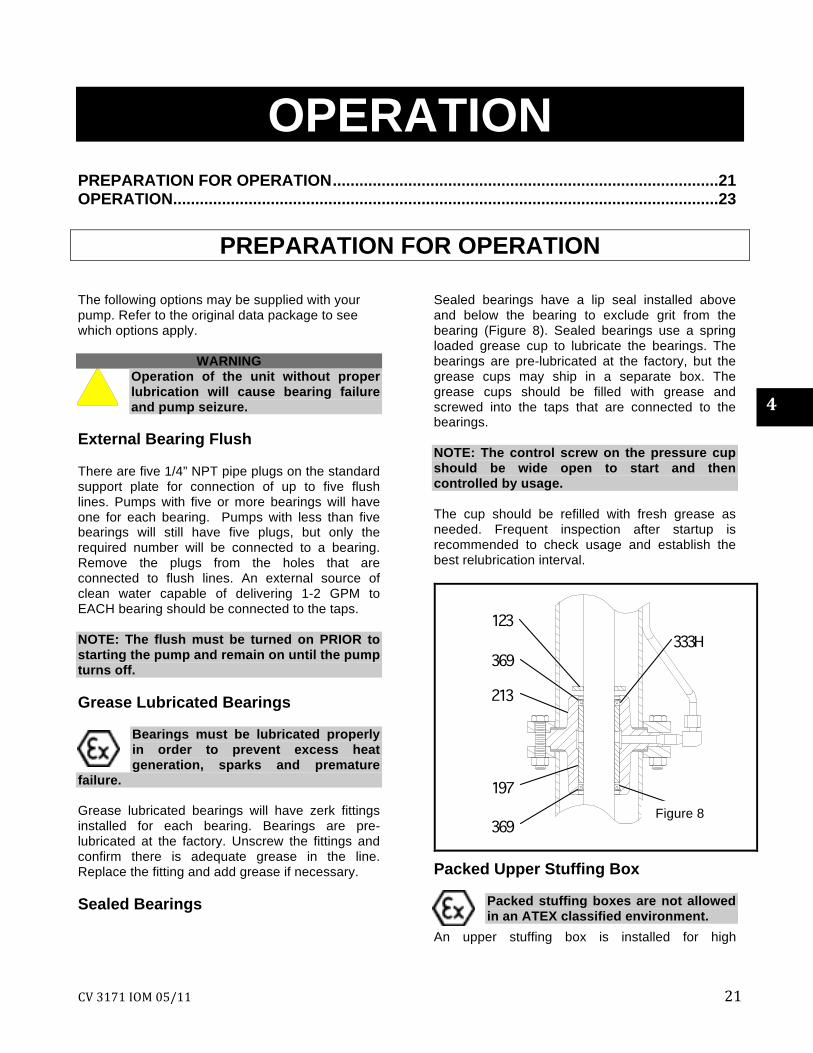
Sealed bearings have a lip seal installed above and below the bearing to exclude grit from the bearing (Figure 8). Sealed bearings use a spring loaded grease cup to lubricate the bearings. The bearings are pre-lubricated at the factory, but the grease cups may ship in a separate box. The grease cups should be filled with grease and screwed into the taps that are connected to the bearings. NOTE: The control screw on the pressure cup should be wide open to start and then controlled by usage. The cup should be refilled with fresh grease as needed. Frequent inspection after startup is recommended to check usage and establish the best relubrication interval.
Packed Upper Stuffing Box Packed stuffing boxes are not allowed in an ATEX classified environment.
An upper stuffing box is installed for high
Figure 8
4

22 CV 3171 IOM 05/11
temperatures and vapor proof construction. The standard configuration is packed. Since no fluid is in the column to lubricate the packing, the packing is grease lubed. The packing is installed at the factory prior to shipment. A screw type grease cup is provided for the packed box. Fill the cup with grease and give the cap several turns to force grease into the packing. Fresh grease should be installed on a regular basis to insure constant lubrication for the packing. Frequent inspection after startup is recommended to check usage and establish the best relubrication interval. Mechanical Seal Upper Stuffing Box A mechanical seal is frequently supplied on upper stuffing box applications. The seal is installed and set at the factory. Cartridge seals will still have the setting clips installed and should be removed. Refer to the seal manufacturer’s guidelines for any special requirements for the particular seal provided.
The mechanical seal used in an ATEX classified environment must be properly certified.
The mechanical seal must always be properly flushed. Failure to do so will result in excess heat generation and
seal failure.
WARNING Some seals require oil lubrication from a bottle oiler, some are dry running, and some may require external flush plans. Do not allow the seal to run dry
unless it is specifically designed for dry running. Steam Jacketed Pumps The steam jacket connections are located on the support plate. Connect the steam in line to an appropriate source of steam. The steam out/condensate return connections should be made as dictated by the installation requirements. A suitable trap should be used. Float Controls A variety of float controls can be supplied by Goulds. Refer to the float control installation instructions provided with the controls for proper installation procedure. Procedures for some of the more common controls are provided in Appendix I.
Checking Rotation Rotation should have been checked prior to coupling alignment and installation. Refer to previous section if this has not been done. Check For Free Turning Before pump is started, rotate the pump by hand to be sure it turns freely and does not rub or bind. Motor Bearing and Coupling Check to be sure the motor bearings and coupling are properly lubricated, if required. Refer to manufacturers recommendations. Check Impeller Clearance
Improper impeller adjustment could cause contact between the rotating and stationary parts, resulting in a
spark and heat generation.
WARNING Check impeller clearance before
starting pump. The pump efficiency is maintained when the proper impeller clearance is set. The clearance is initially set at the factory. The settings from the factory could change due to piping attachment. Refer to Section 5 for procedures on setting impeller clearance. Coupling Guard and Safety Devices Insure coupling guard and any other safety devices are properly installed. Priming
Pumps that are not self-priming must be fully primed at all times during operation.
Never start the pump until it has been properly primed. The pump casing should be fully submerged prior to starting the pump.
CAUTION Do not run the pump dry, as this may damage the pump and/or steady bearings.
CV 3171 IOM 05/11 23
For Dry Pit/Outside tank mount units: 1. Suction supply line must have adequate fluid
head to prime the pump. 2. Slowly open the suction valve. Starting the Pump 1. Before the pump is started, the external
bearing flush (if specified) must be started. 2. Make sure the pump shaft is freely rotating. 3. Partially open the discharge valve. 4. Start driver. 5. Slowly open discharge valve until the desired
flow is obtained.
CAUTION Observe pump for high vibration levels, bearing temperature, and excessive noise. If normal levels are
exceeded, shut down and resolve.
Immediately observe pressure gauges. If discharge pressure is not quickly attained, stop driver, check submergence level, and attempt to restart.
Start Up Precautions
1. All equipment and personal safety-related devices and controls must be installed and operating properly.
2. To prevent premature pump faiure at initial start up due to dirt or debris in the pipe system, ensure the system has been adequately cleaned and flushed.
3. Variable speed drivers should be brought to rated speed as quickly as possible.
4. Variable speed drivers should not be adjusted or checked for speed governor or overspeed trip settings while coupled to the pump at initial start up. If settings have not been verified, uncouple the unit and refer to driver manufacturer’s instructions for assistance.
6. Pumpage tempartatures in excess of 200°F will require warmup of pump prior to operation. Circulate a small amount of pumpage through the pump until the casing temperature is within 100°F of the pumpage temperature and evenly heated.
CAUTION When starting pump, immediately observe pressure gauges. If discharge pressure is not quickly attained, stop
driver, reprime, and attempt to restart.
OPERATION
General Considerations
CAUTION Always vary capacity with regulating valve in the discharge line. Never throttle
flow from the suction side.
CAUTION Driver may overload if the pumpage specific gravity (density) is greater than
originally assumed, or the rated flow rate is exceeded.
CAUTION
Always operate the pump at or near the rated conditions to prevent damage resulting from cavitation or recirculation.
4

24 CV 3171 IOM 05/11
Operating At Reduced Capacity
WARNING DO NOT operate pump below minimum rated flows or with discharge valve closed. These
conditions may create an explosive hazard due to vaporization of pumpage and can quickly lead to pump failure and physical injury. A centrifugal pump should never be operated continuously near shut-off or zero capacity, or with the discharge valve closed. To do so may shorten the life of the pump and greatly increase down time and maintenance.
CAUTION Damage occurs from:
1. Increased vibration levels - affects bearings, stuffing box or seal chamber, and mechanical seal.
2. Increased radial loads – Stresses on shaft
and bearings. 3. Heat buildup - Vaporization causing
rotating parts to score or seize. 4. Cavitation - Damage to internal surfaces of
pump.
CAUTION Serious damage may result if the pump is run in the wrong direction.
CAUTION
Operation of the unit without proper lubrication will cause bearing failure, and pump
seizure. Operating At Reduced Head On motor driven pumps, when discharge head is dropped below the rated point, the motor should be watched for overloading. If this condition is likely to persist, arrangements should be made to either manually or automatically throttle the discharge valve to build up head to prevent overloading.
Operating With Surge Conditions If pump is installed with a quick closing valve in the discharge line that closes when the pump is running, dangerous pressure surges may be built up that can cause damage to the pump or line. In services of this kind, some cushioning arrangement must be provided to protect the pumping equipment. Operating Under Freezing Conditions Exposure to freezing conditions while pump is idle could cause liquid to freeze and damage the pump. Liquid inside pump should be drained. Final Alignment/Clearance Check 1. Run the unit under actual operating conditions
for a sufficient length of time to bring the pump and driver up to operating temperature.
2. Check alignment while unit is still hot per
alignment procedure. 3. Reinstall coupling guard.
The coupling guard used in an ATEX classified environment must be constructed from a
non-sparking material.
CV 3171 IOM 05/11 25
PREVENTIVE MAINTENANCE
GENERAL COMMENTS ...................................................................................................... 25 MAINTENANCE SCHEDULE............................................................................................... 25 MAINTENANCE OF BALL/STEADY BEARINGS ............................................................... 26 MAINTENANCE OF UPPER STUFFING BOX .................................................................... 27 IMPELLER CLEARANCE SETTING – CV 3171.................................................................. 28 IMPELLER CLEARANCE SETTING – LF Sizes TROUBLESHOOTING ......................................................................................................... 31
GENERAL COMMENTS A routine maintenance program can extend the life of your pump. Well-maintained equipment will last longer and require fewer repairs. Accurate records should be kept as they will identify trends and help pinpoint potential causes of problems.
MAINTENANCE SCHEDULE ROUTINE MAINTENANCE Bearing lubrication
Discharge pressure
Temperature monitoring
Vibration analysis
Seal monitoring (when applicable)
ROUTINE INSPECTIONS Check for unusual noise, vibration and thrust
bearing temperatures Check float controls for proper setting and
operation Inspect pump and piping for leaks Check grease for thrust bearing. Refer to
Table 1, Section 5 for lubrication intervals. Grease steady bearings if applicable, adjust
grease cups if supplied Check upper stuffing box leakage. Adjust or
replace packing if required (when applicable) 3 MONTH INSPECTIONS Check anchor bolts for tightness If pump has been idle, check carbon steel
shafts (if applicable) for rust and seizing by rotating the shaft several turns. Replace if required.
Ball (thrust) bearing grease should be changed at least every 3 months or according to Table 1, whichever occurs first. Change grease more
often if there are any adverse conditions which may contaminate the grease. Grease should be injected while turning the shaft until fresh grease comes out.
• Check coupling alignment and realign if required
ANNUAL INSPECTIONS • Check pump capacity, pressure and power. If
pump performance does not satisfy your process requirements, and process requirements or the piping system has not changed, pump should be disassembled, inspected, and worn parts should be replaced. If there is no sign of wear, a system inspection should be done.
The Preventive Maintenance section must be adhered to in order to keep the applicable ATEX classification of the
equipment. Failure to follow these procedures will void the ATEX classification for the equipment.
Inspection intervals should be shortened appropriately if the pumpage is abrasive and/or corrosive,
or if the environment is classified as potentially explosive.
5
26 CV 3171 IOM 05/11
MAINTENANCE OF BALL/STEADY BEARINGS
BALL BEARINGS The angular contact (thrust) bearing is pre-lubricated at the factory. Regrease the bearing according to Table 1. STEADY BEARINGS
Steady bearings requiring grease lubrication are pre-lubricated at the factory. Most bearings are set up to automatically dispense lubrication via grease cups mounted on the support plate. Metallic steady bearings are grease lubricated. It becomes difficult to keep grease in the housings when handling hot liquids, caustic solutions or solvents. Lack of lubrication can cause galling and eventual seizing. Sealed bearings are grease lubricated but they retain the grease due to their dual seals on top and bottom. If pressure cups are used they must be kept full of grease at all times. If manual greasing is used, regrease according to Table 1.
TABLE 1 LUBRICATING INTERVALS
IN OPERATING HOURS
SPEED
<1800 RPM
1800 RPM
3000 RPM
3600 RPM
GROUP
S/ST 2000 2000 1200 750
M/MT 2000 1800 800 450 L 2000 1200 N/A N/A
REGREASE PROCEDURE - BALL BEARING: NOTE: When regreasing there is danger of impurities entering the bearing shell. The grease, the greasing device, and fittings must be clean. 1. Wipe dirt from grease fittings.
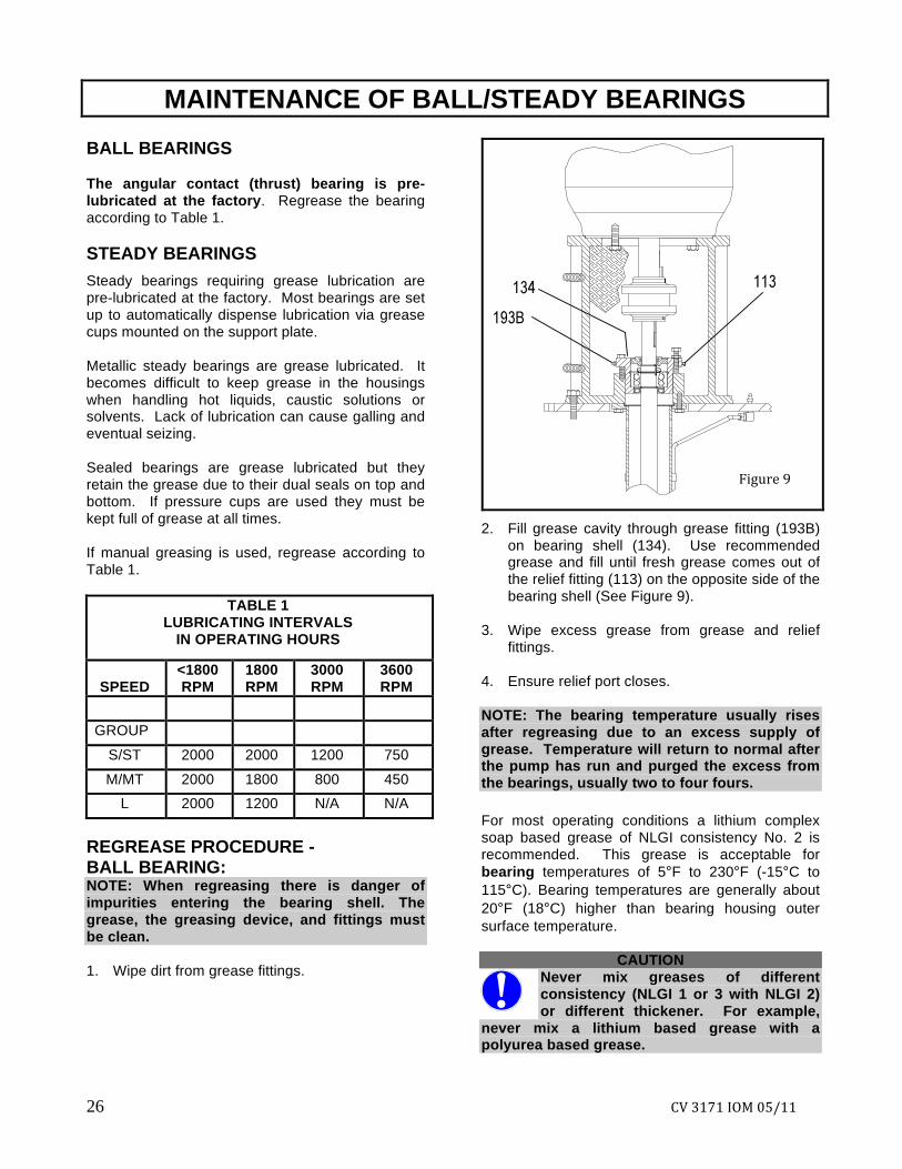
2. Fill grease cavity through grease fitting (193B)
on bearing shell (134). Use recommended grease and fill until fresh grease comes out of the relief fitting (113) on the opposite side of the bearing shell (See Figure 9).
3. Wipe excess grease from grease and relief
fittings. 4. Ensure relief port closes. NOTE: The bearing temperature usually rises after regreasing due to an excess supply of grease. Temperature will return to normal after the pump has run and purged the excess from the bearings, usually two to four fours. For most operating conditions a lithium complex soap based grease of NLGI consistency No. 2 is recommended. This grease is acceptable for bearing temperatures of 5°F to 230°F (-15°C to 115°C). Bearing temperatures are generally about 20°F (18°C) higher than bearing housing outer surface temperature.
CAUTION Never mix greases of different consistency (NLGI 1 or 3 with NLGI 2) or different thickener. For example,
never mix a lithium based grease with a polyurea based grease.
Figure 9
CV 3171 IOM 05/11 27
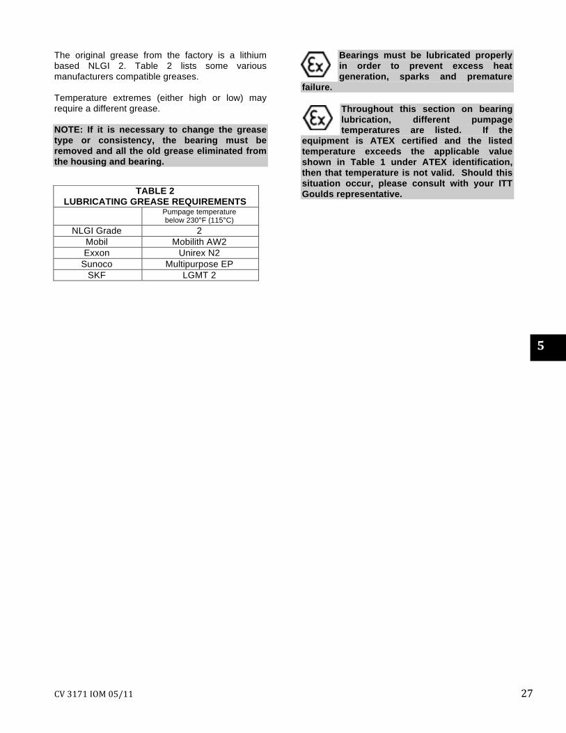
The original grease from the factory is a lithium based NLGI 2. Table 2 lists some various manufacturers compatible greases. Temperature extremes (either high or low) may require a different grease. NOTE: If it is necessary to change the grease type or consistency, the bearing must be removed and all the old grease eliminated from the housing and bearing.
Bearings must be lubricated properly in order to prevent excess heat generation, sparks and premature
failure.
Throughout this section on bearing lubrication, different pumpage temperatures are listed. If the
equipment is ATEX certified and the listed temperature exceeds the applicable value shown in Table 1 under ATEX identification, then that temperature is not valid. Should this situation occur, please consult with your ITT Goulds representative.
5
TABLE 2 LUBRICATING GREASE REQUIREMENTS
Pumpage temperature below 230°F (115°C)
NLGI Grade 2 Mobil Mobilith AW2 Exxon Unirex N2
Sunoco Multipurpose EP SKF LGMT 2
28 CV 3171 IOM 05/11
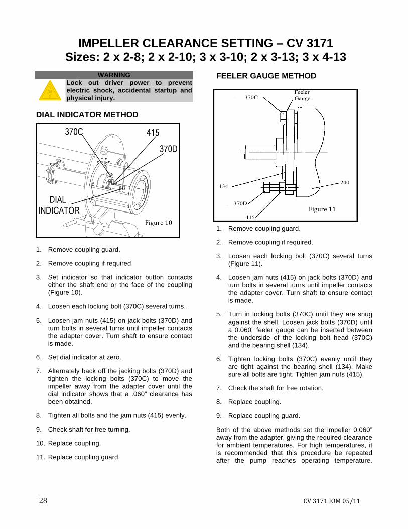
IMPELLER CLEARANCE SETTING – CV 3171 Sizes: 2 x 2-8; 2 x 2-10; 3 x 3-10; 2 x 3-13; 3 x 4-13
WARNING
Lock out driver power to prevent electric shock, accidental startup and physical injury.
DIAL INDICATOR METHOD
1. Remove coupling guard. 2. Remove coupling if required 3. Set indicator so that indicator button contacts
either the shaft end or the face of the coupling (Figure 10).
4. Loosen each locking bolt (370C) several turns. 5. Loosen jam nuts (415) on jack bolts (370D) and
turn bolts in several turns until impeller contacts the adapter cover. Turn shaft to ensure contact is made.
6. Set dial indicator at zero. 7. Alternately back off the jacking bolts (370D) and
tighten the locking bolts (370C) to move the impeller away from the adapter cover until the dial indicator shows that a .060” clearance has been obtained.
8. Tighten all bolts and the jam nuts (415) evenly. 9. Check shaft for free turning. 10. Replace coupling. 11. Replace coupling guard.
FEELER GAUGE METHOD
1. Remove coupling guard. 2. Remove coupling if required. 3. Loosen each locking bolt (370C) several turns
(Figure 11). 4. Loosen jam nuts (415) on jack bolts (370D) and
turn bolts in several turns until impeller contacts the adapter cover. Turn shaft to ensure contact is made.
5. Turn in locking bolts (370C) until they are snug
against the shell. Loosen jack bolts (370D) until a 0.060” feeler gauge can be inserted between the underside of the locking bolt head (370C) and the bearing shell (134).
6. Tighten locking bolts (370C) evenly until they
are tight against the bearing shell (134). Make sure all bolts are tight. Tighten jam nuts (415).
7. Check the shaft for free rotation. 8. Replace coupling. 9. Replace coupling guard. Both of the above methods set the impeller 0.060” away from the adapter, giving the required clearance for ambient temperatures. For high temperatures, it is recommended that this procedure be repeated after the pump reaches operating temperature.
Figure 10
Figure 11
CV 3171 IOM 05/11 29
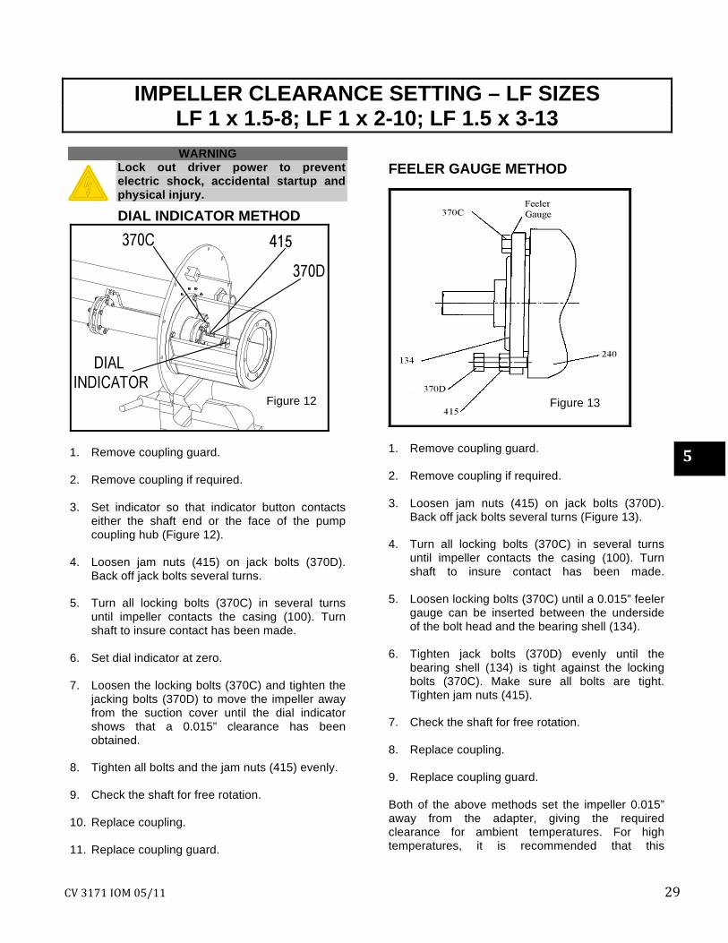
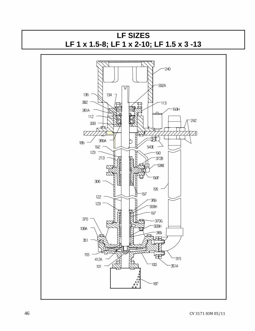
IMPELLER CLEARANCE SETTING – LF SIZES LF 1 x 1.5-8; LF 1 x 2-10; LF 1.5 x 3-13
WARNING
Lock out driver power to prevent electric shock, accidental startup and physical injury.
DIAL INDICATOR METHOD
1. Remove coupling guard. 2. Remove coupling if required. 3. Set indicator so that indicator button contacts
either the shaft end or the face of the pump coupling hub (Figure 12).
4. Loosen jam nuts (415) on jack bolts (370D).
Back off jack bolts several turns. 5. Turn all locking bolts (370C) in several turns
until impeller contacts the casing (100). Turn shaft to insure contact has been made.
6. Set dial indicator at zero. 7. Loosen the locking bolts (370C) and tighten the
jacking bolts (370D) to move the impeller away from the suction cover until the dial indicator shows that a 0.015” clearance has been obtained.
8. Tighten all bolts and the jam nuts (415) evenly. 9. Check the shaft for free rotation. 10. Replace coupling. 11. Replace coupling guard.
FEELER GAUGE METHOD
1. Remove coupling guard. 2. Remove coupling if required. 3. Loosen jam nuts (415) on jack bolts (370D).
Back off jack bolts several turns (Figure 13). 4. Turn all locking bolts (370C) in several turns
until impeller contacts the casing (100). Turn shaft to insure contact has been made.
5. Loosen locking bolts (370C) until a 0.015” feeler gauge can be inserted between the underside of the bolt head and the bearing shell (134).
6. Tighten jack bolts (370D) evenly until the
bearing shell (134) is tight against the locking bolts (370C). Make sure all bolts are tight. Tighten jam nuts (415).
7. Check the shaft for free rotation. 8. Replace coupling. 9. Replace coupling guard. Both of the above methods set the impeller 0.015” away from the adapter, giving the required clearance for ambient temperatures. For high temperatures, it is recommended that this
Figure 12 Figure 13
5
30 CV 3171 IOM 05/11
procedure be repeated after the pump reaches operating temperature.
The impeller clearance setting procedure must be followed. Improperly setting the clearance or not
following any of the proper procedures can result in sparks, unexpected heat generation and equipment damage.
CV 3171 IOM 05/11 31
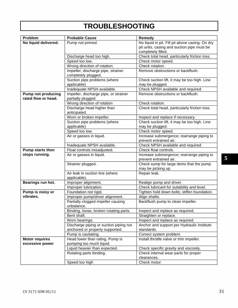
TROUBLESHOOTING Problem Probable Cause Remedy
Pump not primed. No liquid in pit. Fill pit above casing. On dry pit units, casing and suction pipe must be completely filled.
Discharge head too high. Check total head, particularly friction loss. Speed too low. Check motor speed. Wrong direction of rotation. Check rotation. Impeller, discharge pipe, strainer completely plugged.
Remove obstructions or backflush.
Suction pipe problems (where applicable)
Check suction lift, it may be too high. Line may be plugged.
No liquid delivered.
Inadequate NPSH available. Check NPSH available and required. Impeller, discharge pipe, or strainer partially plugged.
Remove obstructions or backflush.
Wrong direction of rotation Check rotation. Discharge head higher than anticipated.
Check total head, particularly friction loss.
Worn or broken impeller. Inspect and replace if necessary. Suction pipe problems (where applicable)
Check suction lift, it may be too high. Line may be plugged.
Speed too low. Check motor speed. Air or gasses in liquid. Increase submergence; rearrange piping to
prevent entrained air.
Pump not producing rated flow or head.
Inadequate NPSH available. Check NPSH available and required. Float controls misadjusted. Check float controls. Air or gasses in liquid. Increase submergence; rearrange piping to
prevent entrained air. Strainer plugged. Check sump for large items that the pump
may be picking up.
Pump starts then stops running.
Air leak in suction line (where applicable).
Repair leak.
Improper alignment. Realign pump and driver. Bearings run hot. Improper lubrication. Check lubricant for suitability and level. Foundation not rigid. Tighten hold down bolts; stiffen foundation. Improper pump/driver alignment. Align shafts. Partially clogged impeller causing unbalance.
Backflush pump to clean impeller.
Binding, loose, broken rotating parts. Inspect and replace as required. Bent shaft. Straighten or replace. Worn bearings. Inspect and replace as required. Discharge piping or suction piping not anchored or properly supported.
Anchor and support per Hydraulic Institute standards.
Pump is noisy or vibrates.
Pump is cavitating. Correct system problem. Head lower than rating. Pump is pumping too much liquid.
Install throttle valve or trim impeller.
Liquid heavier than expected. Check specific gravity and viscosity. Rotating parts binding. Check internal wear parts for proper
clearances.
Motor requires excessive power
Speed too high Check motor.
5

32 CV 3171 IOM 05/11
THIS PAGE INTENTIONALLY LEFT BLANK
CV 3171 IOM 05/11 33
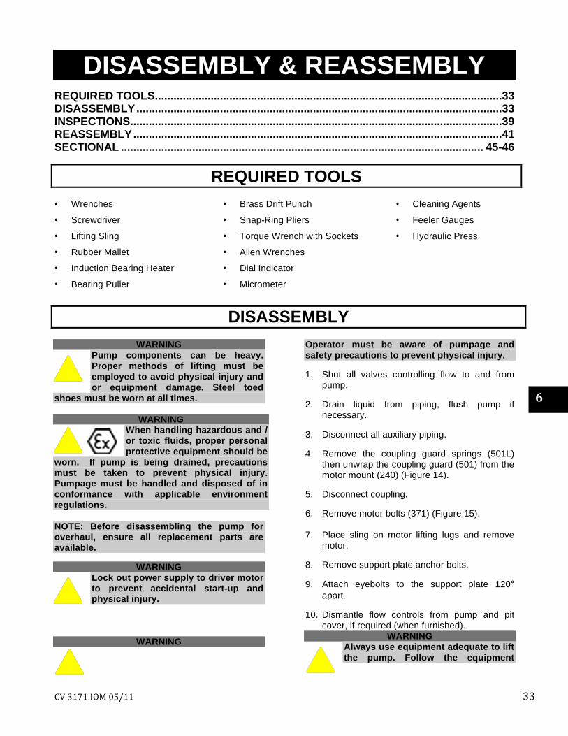
DISASSEMBLY & REASSEMBLYREQUIRED TOOLS................................................................................................................33 DISASSEMBLY......................................................................................................................33 INSPECTIONS........................................................................................................................39 REASSEMBLY.......................................................................................................................41 SECTIONAL ..................................................................................................................... 45-46
REQUIRED TOOLS • Wrenches
• Screwdriver
• Lifting Sling
• Rubber Mallet
• Induction Bearing Heater
• Bearing Puller
• Brass Drift Punch
• Snap-Ring Pliers
• Torque Wrench with Sockets
• Allen Wrenches
• Dial Indicator
• Micrometer
• Cleaning Agents
• Feeler Gauges
• Hydraulic Press
DISASSEMBLY
WARNING Pump components can be heavy. Proper methods of lifting must be employed to avoid physical injury and or equipment damage. Steel toed
shoes must be worn at all times.
WARNING When handling hazardous and / or toxic fluids, proper personal protective equipment should be
worn. If pump is being drained, precautions must be taken to prevent physical injury. Pumpage must be handled and disposed of in conformance with applicable environment regulations. NOTE: Before disassembling the pump for overhaul, ensure all replacement parts are available.
WARNING
Lock out power supply to driver motor to prevent accidental start-up and physical injury.
WARNING
Operator must be aware of pumpage and safety precautions to prevent physical injury. 1. Shut all valves controlling flow to and from
pump. 2. Drain liquid from piping, flush pump if
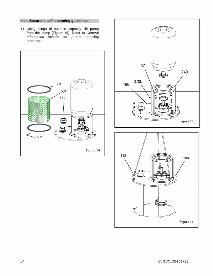
necessary. 3. Disconnect all auxiliary piping. 4. Remove the coupling guard springs (501L)
then unwrap the coupling guard (501) from the motor mount (240) (Figure 14).
5. Disconnect coupling. 6. Remove motor bolts (371) (Figure 15). 7. Place sling on motor lifting lugs and remove
motor. 8. Remove support plate anchor bolts. 9. Attach eyebolts to the support plate 120°
apart. 10. Dismantle flow controls from pump and pit
cover, if required (when furnished). WARNING
Always use equipment adequate to lift the pump. Follow the equipment
6
34 CV 3171 IOM 05/11
manufacturer’s safe operating guidelines. 11. Using slings of suitable capacity, lift pump
from the sump (Figure 16). Refer to General Information section for proper handling procedure.
Figure 14
Figure 15
Figure 16
CV 3171 IOM 05/11 35
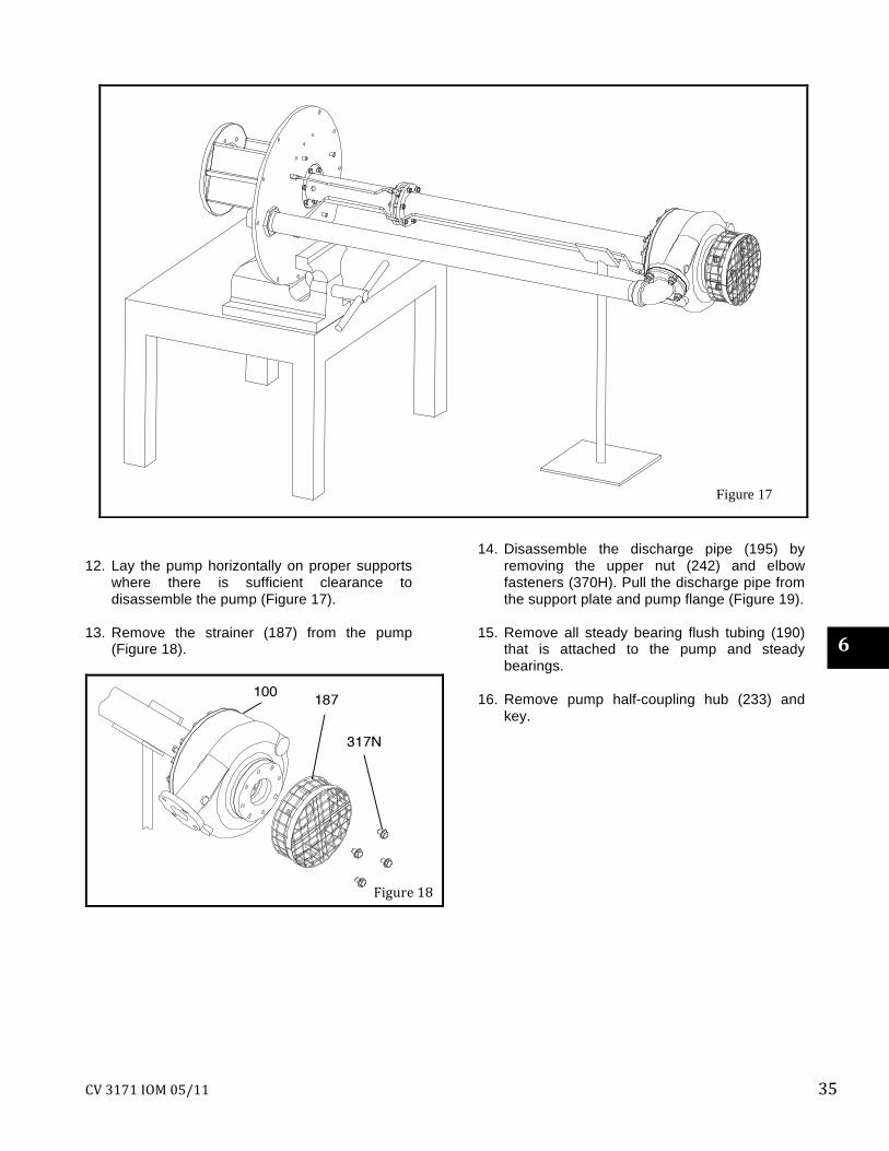
12. Lay the pump horizontally on proper supports
where there is sufficient clearance to disassemble the pump (Figure 17).
13. Remove the strainer (187) from the pump
(Figure 18).
14. Disassemble the discharge pipe (195) by
removing the upper nut (242) and elbow fasteners (370H). Pull the discharge pipe from the support plate and pump flange (Figure 19).
15. Remove all steady bearing flush tubing (190)
that is attached to the pump and steady bearings.
16. Remove pump half-coupling hub (233) and
key.
Figure 18
6
Figure 17

36 CV 3171 IOM 05/11
17. Disassemble the pump casing (100) by removing the casing to adapter bolts (370). Leave the jacking bolts (418) in place. When removing the casing, be careful not to mar the inside casing walls (Figure 20).
WARNING When removing impeller, wear heavy work gloves to prevent cutting hands on sharp edges of impeller vanes.
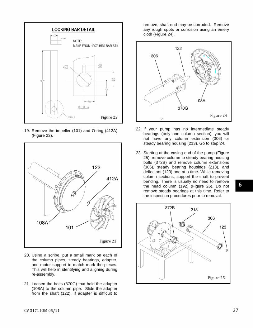
18. Remove the impeller (101) from the shaft (122). One method is by using a locking bar to break the thread grip on the impeller. Attach the locking bar (locking bar detail can be found in Figure 22) onto the power end of the pump shaft. Quickly turn impeller counter clockwise as viewed from the impeller end of the shaft (right hand thread) impacting the locking bar handle on the motor support. Repeat this process until the impeller breaks free (Figure 21).
Figure 20
Figure 21
Figure 19
CV 3171 IOM 05/11 37
19. Remove the impeller (101) and O-ring (412A)
(Figure 23).
20. Using a scribe, put a small mark on each of
the column pipes, steady bearings, adapter, and motor support to match mark the pieces. This will help in identifying and aligning during re-assembly.
21. Loosen the bolts (370G) that hold the adapter
(108A) to the column pipe. Slide the adapter from the shaft (122). If adapter is difficult to
remove, shaft end may be corroded. Remove any rough spots or corrosion using an emery cloth (Figure 24).
22. If your pump has no intermediate steady
bearings (only one column section), you will not have any column extension (306) or steady bearing housing (213). Go to step 24.
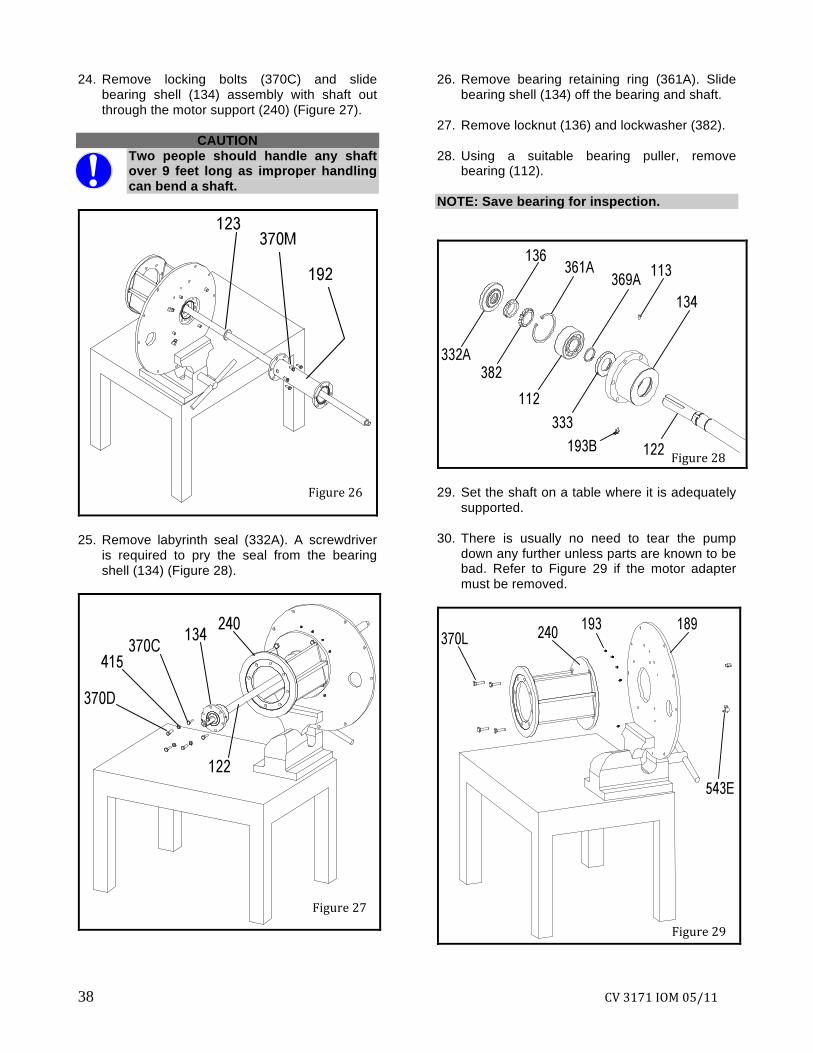
23. Starting at the casing end of the pump (Figure
25), remove column to steady bearing housing bolts (372B) and remove column extensions (306), steady bearing housings (213), and deflectors (123) one at a time. While removing column sections, support the shaft to prevent bending. There is usually no need to remove the head column (192) (Figure 26). Do not remove steady bearings at this time. Refer to the inspection procedures prior to removal.
Figure 22
Figure 23
Figure 24
Figure 25
6
38 CV 3171 IOM 05/11
24. Remove locking bolts (370C) and slide bearing shell (134) assembly with shaft out through the motor support (240) (Figure 27).
CAUTION
Two people should handle any shaft over 9 feet long as improper handling can bend a shaft.
25. Remove labyrinth seal (332A). A screwdriver
is required to pry the seal from the bearing shell (134) (Figure 28).
26. Remove bearing retaining ring (361A). Slide bearing shell (134) off the bearing and shaft.
27. Remove locknut (136) and lockwasher (382). 28. Using a suitable bearing puller, remove
bearing (112). NOTE: Save bearing for inspection.
29. Set the shaft on a table where it is adequately
supported. 30. There is usually no need to tear the pump
down any further unless parts are known to be bad. Refer to Figure 29 if the motor adapter must be removed.
Figure 26
Figure 27
Figure 29
Figure 28
CV 3171 IOM 05/11 39
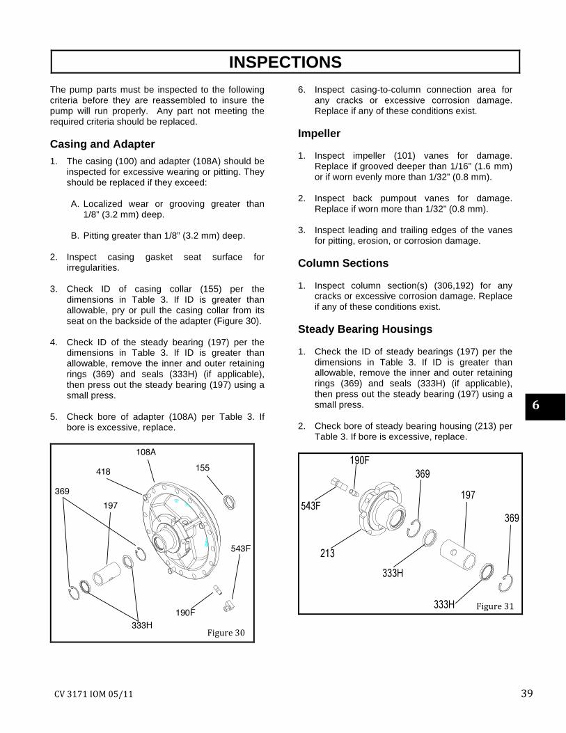
INSPECTIONS The pump parts must be inspected to the following criteria before they are reassembled to insure the pump will run properly. Any part not meeting the required criteria should be replaced. Casing and Adapter 1. The casing (100) and adapter (108A) should be
inspected for excessive wearing or pitting. They should be replaced if they exceed:
A. Localized wear or grooving greater than
1/8” (3.2 mm) deep. B. Pitting greater than 1/8” (3.2 mm) deep.
2. Inspect casing gasket seat surface for
irregularities. 3. Check ID of casing collar (155) per the
dimensions in Table 3. If ID is greater than allowable, pry or pull the casing collar from its seat on the backside of the adapter (Figure 30).
4. Check ID of the steady bearing (197) per the
dimensions in Table 3. If ID is greater than allowable, remove the inner and outer retaining rings (369) and seals (333H) (if applicable), then press out the steady bearing (197) using a small press.
5. Check bore of adapter (108A) per Table 3. If
bore is excessive, replace.
6. Inspect casing-to-column connection area for any cracks or excessive corrosion damage. Replace if any of these conditions exist.
Impeller 1. Inspect impeller (101) vanes for damage.
Replace if grooved deeper than 1/16” (1.6 mm) or if worn evenly more than 1/32” (0.8 mm).
2. Inspect back pumpout vanes for damage.
Replace if worn more than 1/32” (0.8 mm). 3. Inspect leading and trailing edges of the vanes
for pitting, erosion, or corrosion damage. Column Sections 1. Inspect column section(s) (306,192) for any
cracks or excessive corrosion damage. Replace if any of these conditions exist.
Steady Bearing Housings 1. Check the ID of steady bearings (197) per the
dimensions in Table 3. If ID is greater than allowable, remove the inner and outer retaining rings (369) and seals (333H) (if applicable), then press out the steady bearing (197) using a small press.
2. Check bore of steady bearing housing (213) per
Table 3. If bore is excessive, replace.
Figure 31
6
Figure 30
40 CV 3171 IOM 05/11
Table 3 Steady Bearing Tolerances
Bearing ID (pressed in place) Housing Bore Running Clearance
(1/2 diametrical clearance) Bearing Material
S/ST M/MT L S/ST M/MT L S/ST M/MT L Carbon 1.132/1.134 1.633/1.635 2.258/2.260 1.620/1.622 2.120/2.122 2.993/2.995 0.0055/0.0035 0.006/0.004 0.0065/0.004 Bronze 1.129/1.131 1.629/1.631 2.256/2.258 1.620/1.622 2.120/2.122 2.993/2.995 0.004/0.002 0.004/0.002 0.0055/0.003
Fluted Elastomer
1.126/1.130 1.627/1.632 2.253/2.257 1.620/1.622 2.120/2.122 2.993/2.995 0.0035/0.0005 0.0045/0.001 0.005/0.004
Rulon 1.132/1.134 1.633/1.635 2.258/2.260 0.0055/0.0035 0.006/0.004 0.0065/0.004
S/ST M/MT L S/ST M/MT L S/ST M/MT L Casing Collar 1.183/1.190 1.678/1.685 2.299/2.306 1.811/1.813 2.243/2.245 3.243/3.245 0.0335/0.029 0.031/0.0265 0.029/0.0245
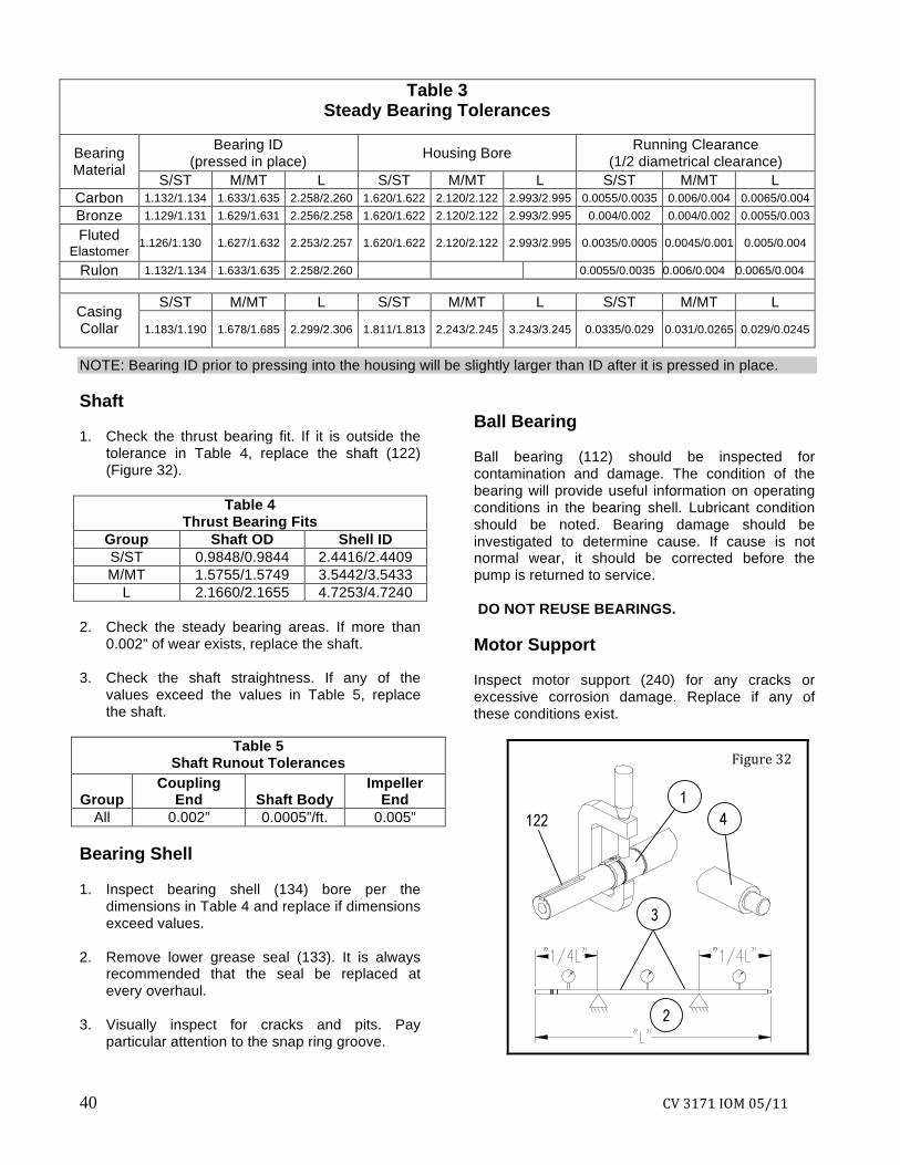
NOTE: Bearing ID prior to pressing into the housing will be slightly larger than ID after it is pressed in place. Shaft 1. Check the thrust bearing fit. If it is outside the
tolerance in Table 4, replace the shaft (122) (Figure 32).
Table 4
Thrust Bearing Fits Group Shaft OD Shell ID S/ST 0.9848/0.9844 2.4416/2.4409 M/MT 1.5755/1.5749 3.5442/3.5433
L 2.1660/2.1655 4.7253/4.7240 2. Check the steady bearing areas. If more than
0.002” of wear exists, replace the shaft. 3. Check the shaft straightness. If any of the
values exceed the values in Table 5, replace the shaft.
Table 5
Shaft Runout Tolerances
Group Coupling
End
Shaft Body Impeller
End All 0.002” 0.0005”/ft. 0.005”
Bearing Shell 1. Inspect bearing shell (134) bore per the
dimensions in Table 4 and replace if dimensions exceed values.
2. Remove lower grease seal (133). It is always
recommended that the seal be replaced at every overhaul.
3. Visually inspect for cracks and pits. Pay
particular attention to the snap ring groove.
Ball Bearing Ball bearing (112) should be inspected for contamination and damage. The condition of the bearing will provide useful information on operating conditions in the bearing shell. Lubricant condition should be noted. Bearing damage should be investigated to determine cause. If cause is not normal wear, it should be corrected before the pump is returned to service. DO NOT REUSE BEARINGS. Motor Support Inspect motor support (240) for any cracks or excessive corrosion damage. Replace if any of these conditions exist.
Figure 32
CV 3171 IOM 05/11 41
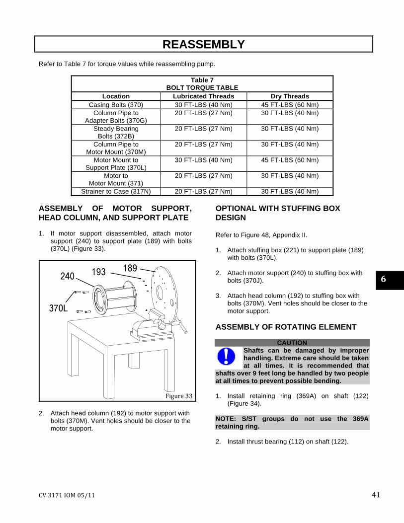
REASSEMBLY Refer to Table 7 for torque values while reassembling pump.
Table 7 BOLT TORQUE TABLE
Location Lubricated Threads Dry Threads Casing Bolts (370) 30 FT-LBS (40 Nm) 45 FT-LBS (60 Nm)
Column Pipe to Adapter Bolts (370G)
20 FT-LBS (27 Nm) 30 FT-LBS (40 Nm)
Steady Bearing Bolts (372B)
20 FT-LBS (27 Nm) 30 FT-LBS (40 Nm)
Column Pipe to Motor Mount (370M)
20 FT-LBS (27 Nm) 30 FT-LBS (40 Nm)
Motor Mount to Support Plate (370L)
30 FT-LBS (40 Nm) 45 FT-LBS (60 Nm)
Motor to Motor Mount (371)
20 FT-LBS (27 Nm) 30 FT-LBS (40 Nm)
Strainer to Case (317N) 20 FT-LBS (27 Nm) 30 FT-LBS (40 Nm) ASSEMBLY OF MOTOR SUPPORT, HEAD COLUMN, AND SUPPORT PLATE 1. If motor support disassembled, attach motor
support (240) to support plate (189) with bolts (370L) (Figure 33).
2. Attach head column (192) to motor support with
bolts (370M). Vent holes should be closer to the motor support.
OPTIONAL WITH STUFFING BOX DESIGN Refer to Figure 48, Appendix II. 1. Attach stuffing box (221) to support plate (189)
with bolts (370L). 2. Attach motor support (240) to stuffing box with
bolts (370J). 3. Attach head column (192) to stuffing box with
bolts (370M). Vent holes should be closer to the motor support.
ASSEMBLY OF ROTATING ELEMENT
CAUTION Shafts can be damaged by improper handling. Extreme care should be taken at all times. It is recommended that
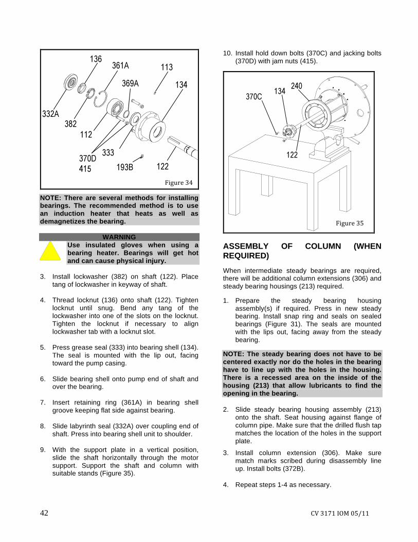
shafts over 9 feet long be handled by two people at all times to prevent possible bending. 1. Install retaining ring (369A) on shaft (122)
(Figure 34). NOTE: S/ST groups do not use the 369A retaining ring. 2. Install thrust bearing (112) on shaft (122).
Figure 33
6
42 CV 3171 IOM 05/11
NOTE: There are several methods for installing bearings. The recommended method is to use an induction heater that heats as well as demagnetizes the bearing.
WARNING Use insulated gloves when using a bearing heater. Bearings will get hot and can cause physical injury.
3. Install lockwasher (382) on shaft (122). Place
tang of lockwasher in keyway of shaft. 4. Thread locknut (136) onto shaft (122). Tighten
locknut until snug. Bend any tang of the lockwasher into one of the slots on the locknut. Tighten the locknut if necessary to align lockwasher tab with a locknut slot.
5. Press grease seal (333) into bearing shell (134).
The seal is mounted with the lip out, facing toward the pump casing.
6. Slide bearing shell onto pump end of shaft and
over the bearing. 7. Insert retaining ring (361A) in bearing shell
groove keeping flat side against bearing. 8. Slide labyrinth seal (332A) over coupling end of
shaft. Press into bearing shell unit to shoulder. 9. With the support plate in a vertical position,
slide the shaft horizontally through the motor support. Support the shaft and column with suitable stands (Figure 35).
10. Install hold down bolts (370C) and jacking bolts (370D) with jam nuts (415).
ASSEMBLY OF COLUMN (WHEN REQUIRED) When intermediate steady bearings are required, there will be additional column extensions (306) and steady bearing housings (213) required. 1. Prepare the steady bearing housing
assembly(s) if required. Press in new steady bearing. Install snap ring and seals on sealed bearings (Figure 31). The seals are mounted with the lips out, facing away from the steady bearing.
NOTE: The steady bearing does not have to be centered exactly nor do the holes in the bearing have to line up with the holes in the housing. There is a recessed area on the inside of the housing (213) that allow lubricants to find the opening in the bearing.
2. Slide steady bearing housing assembly (213) onto the shaft. Seat housing against flange of column pipe. Make sure that the drilled flush tap matches the location of the holes in the support plate.
3. Install column extension (306). Make sure match marks scribed during disassembly line up. Install bolts (372B).
4. Repeat steps 1-4 as necessary.
Figure 35
Figure 34
CV 3171 IOM 05/11 43
ASSEMBLE LIQUID END
1. Press casing collar (155) into adapter (108A) using a suitable press.
2. Prepare the adapter (108A) if required. Press in new steady bearing. Install snap ring and seals on sealed bearings (Figure 30). The seals are mounted with the lips out, facing away from the steady bearing.
NOTE: The steady bearing does not have to be centered exactly nor do the holes in the bearing have to line up with the holes in the housing. There is a recessed area on the inside of the adapter (108A) that allows lubricants to find the opening in the bearing.
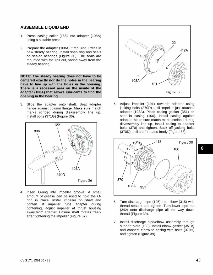
3. Slide the adapter onto shaft. Seat adapter flange against column flange. Make sure match marks scribed during disassembly line up. Install bolts (371G) (Figure 36).
4. Insert O-ring into impeller groove. A small amount of grease can be used to hold the O-ring in place. Install impeller on shaft and tighten. If impeller rubs adapter during tightening, adjust impeller at thrust housing away from adapter. Ensure shaft rotates freely after tightening the impeller (Figure 37).
5. Adjust impeller (101) towards adapter using jacking bolts (370D) until impeller just touches adapter (108A). Place casing gasket (351) on seat in casing (100). Install casing against adapter. Make sure match marks scribed during disassembly line up. Install casing to adapter bolts (370) and tighten. Back off jacking bolts (370D) until shaft rotates freely (Figure 38).
6. Turn discharge pipe (195) into elbow (315) with thread sealant and tighten. Turn lower pipe nut (242) onto discharge pipe all the way down thread (Figure 39).
7. Install discharge pipe/elbow assembly through support plate (189). Install elbow gasket (351A) and connect elbow to casing with bolts (370H) and tighten (Figure 39).
Figure 38
Figure 37
Figure 36
6
44 CV 3171 IOM 05/11
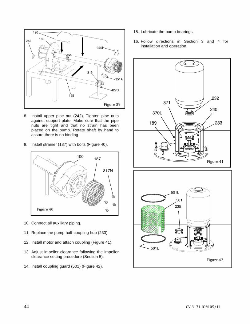
8. Install upper pipe nut (242). Tighten pipe nuts against support plate. Make sure that the pipe nuts are tight and that no strain has been placed on the pump. Rotate shaft by hand to assure there is no binding
9. Install strainer (187) with bolts (Figure 40).
10. Connect all auxiliary piping.
11. Replace the pump half-coupling hub (233).
12. Install motor and attach coupling (Figure 41).
13. Adjust impeller clearance following the impeller clearance setting procedure (Section 5).
14. Install coupling guard (501) (Figure 42).
15. Lubricate the pump bearings.
16. Follow directions in Section 3 and 4 for installation and operation.
Figure 39
Figure 42
Figure 40
Figure 41

CV 3171 IOM 05/11 45
CV 3171 Sizes: 2 x 2-8; 2 x 2-10; 3 x 3-10; 2 x 3-13; 3 x 4-13
6
46 CV 3171 IOM 05/11
LF SIZES LF 1 x 1.5-8; LF 1 x 2-10; LF 1.5 x 3 -13
CV 3171 IOM 05/11 47
APPENDIX I
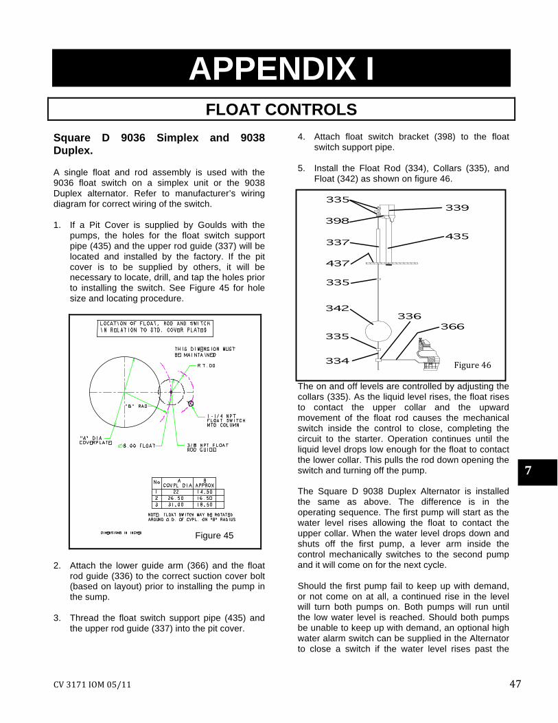
FLOAT CONTROLS Square D 9036 Simplex and 9038 Duplex. A single float and rod assembly is used with the 9036 float switch on a simplex unit or the 9038 Duplex alternator. Refer to manufacturer’s wiring diagram for correct wiring of the switch. 1. If a Pit Cover is supplied by Goulds with the
pumps, the holes for the float switch support pipe (435) and the upper rod guide (337) will be located and installed by the factory. If the pit cover is to be supplied by others, it will be necessary to locate, drill, and tap the holes prior to installing the switch. See Figure 45 for hole size and locating procedure.
2. Attach the lower guide arm (366) and the float
rod guide (336) to the correct suction cover bolt (based on layout) prior to installing the pump in the sump.
3. Thread the float switch support pipe (435) and
the upper rod guide (337) into the pit cover.
4. Attach float switch bracket (398) to the float switch support pipe.
5. Install the Float Rod (334), Collars (335), and
Float (342) as shown on figure 46.
The on and off levels are controlled by adjusting the collars (335). As the liquid level rises, the float rises to contact the upper collar and the upward movement of the float rod causes the mechanical switch inside the control to close, completing the circuit to the starter. Operation continues until the liquid level drops low enough for the float to contact the lower collar. This pulls the rod down opening the switch and turning off the pump. The Square D 9038 Duplex Alternator is installed the same as above. The difference is in the operating sequence. The first pump will start as the water level rises allowing the float to contact the upper collar. When the water level drops down and shuts off the first pump, a lever arm inside the control mechanically switches to the second pump and it will come on for the next cycle. Should the first pump fail to keep up with demand, or not come on at all, a continued rise in the level will turn both pumps on. Both pumps will run until the low water level is reached. Should both pumps be unable to keep up with demand, an optional high water alarm switch can be supplied in the Alternator to close a switch if the water level rises past the
Figure 46
Figure 45
7
48 CV 3171 IOM 05/11
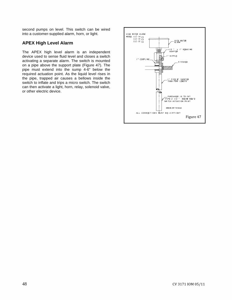
second pumps on level. This switch can be wired into a customer-supplied alarm, horn, or light. APEX High Level Alarm The APEX high level alarm is an independent device used to sense fluid level and closes a switch activating a separate alarm. The switch is mounted on a pipe above the support plate (Figure 47). The pipe must extend into the sump 4-6” below the required actuation point. As the liquid level rises in the pipe, trapped air causes a bellows inside the switch to inflate and trips a micro switch. The switch can then activate a light, horn, relay, solenoid valve, or other electric device.
Figure 47
CV 3171 IOM 05/11 49
Figure 48
193I
355
494V
190G
540M
367B
221
353
107 105 355C
364A
189
106
APPENDIX II
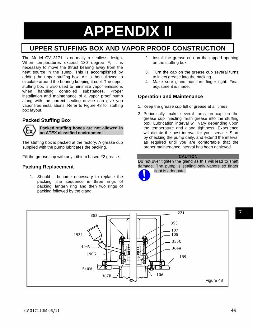
UPPER STUFFING BOX AND VAPOR PROOF CONSTRUCTION The Model CV 3171 is normally a sealless design. When temperatures exceed 180 degree F, it is necessary to move the thrust bearing away from the heat source in the sump. This is accomplished by adding the upper stuffing box. Air is then allowed to circulate around the bearing keeping it cool. The upper stuffing box is also used to minimize vapor emissions when handling controlled substances. Proper installation and maintenance of a vapor proof pump along with the correct sealing device can give you vapor free installations. Refer to Figure 48 for stuffing box layout. Packed Stuffing Box
Packed stuffing boxes are not allowed in an ATEX classified environment
The stuffing box is packed at the factory. A grease cup supplied with the pump lubricates the packing. Fill the grease cup with any Lithium based #2 grease. Packing Replacement
1. Should it become necessary to replace the packing, the sequence is three rings of packing, lantern ring and then two rings of packing followed by the gland.
2. Install the grease cup on the tapped opening on the stuffing box.
3. Turn the cap on the grease cup several turns
to inject grease into the packing. 4. Make sure gland nuts are finger tight. Final
adjustment is made. Operation and Maintenance 1. Keep the grease cup full of grease at all times.
2. Periodically make several turns on cap on the grease cup injecting fresh grease into the stuffing box. Lubrication interval will vary depending upon the temperature and gland tightness. Experience will dictate the best interval for your service. Start by checking the pump daily, and extend the interval as required until you are comfortable that the proper maintenance interval has been achieved.
CAUTION
Do not over tighten the gland as this will lead to shaft damage. The pump is sealing only vapors so finger
tight is adequate.
7
50 CV 3171 IOM 05/11
Mechanical Seals When mechanical seals are furnished, a manufacturer’s reference drawing is supplied with the pump data package. This drawing must be kept for future use when performing maintenance and adjusting the seal. If oil lubed seals are supplied, the seal faces must be lubricated by oil at all times.
CV 3171 IOM 05/11 51
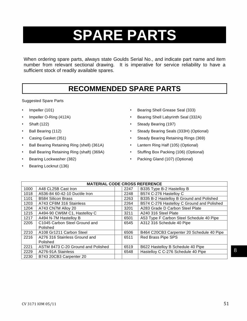
SPARE PARTS When ordering spare parts, always state Goulds Serial No., and indicate part name and item number from relevant sectional drawing. It is imperative for service reliability to have a sufficient stock of readily available spares.
RECOMMENDED SPARE PARTS Suggested Spare Parts • Impeller (101)
• Impeller O-Ring (412A)
• Shaft (122)
• Ball Bearing (112)
• Casing Gasket (351)
• Ball Bearing Retaining Ring (shell) (361A)
• Ball Bearing Retaining Ring (shaft) (369A)
• Bearing Lockwasher (382)
• Bearing Locknut (136)
• Bearing Shell Grease Seal (333)
• Bearing Shell Labyrinth Seal (332A)
• Steady Bearing (197)
• Steady Bearing Seals (333H) (Optional)
• Steady Bearing Retaining Rings (369)
• Lantern Ring Half (105) (Optional)
• Stuffing Box Packing (106) (Optional)
• Packing Gland (107) (Optional)
MATERIAL CODE CROSS REFERENCE
1000 A48 CL25B Cast Iron 2247 B335 Type B-2 Hastelloy B 1018 A536-84 60-42-10 Ductile Iron 2248 B574 C-276 Hastelloy C 1101 B584 Silicon Brass 2263 B335 B-2 Hastelloy B Ground and Polished 1203 A743 CF8M 316 Stainless 2264 B574 C-276 Hastelloy C Ground and Polished 1204 A743 CN7M Alloy 20 3201 A283 Grade D Carbon Steel Plate 1215 A494-90 CW6M C1, Hastelloy C 3211 A240 316 Steel Plate 1217 A494 N-7M Hastelloy B 6501 A53 Type F Carbon Steel Schedule 40 Pipe 2205 C1045 Carbon Steel Ground and
Polished 6545 A312 316 Schedule 40 Pipe
2210 A108 Gr1211 Carbon Steel 6506 B464 C20CB3 Carpenter 20 Schedule 40 Pipe 2216 A276 316 Stainless Ground and
Polished 6511 Red Brass Pipe SPS
2221 ASTM 8473 C-20 Ground and Polished 6519 B622 Hastelloy B Schedule 40 Pipe 2229 A276-91A Stainless 6548 Hastelloy C C-276 Schedule 40 Pipe 2230 B743 20CB3 Carpenter 20
8
52 CV 3171 IOM 05/11
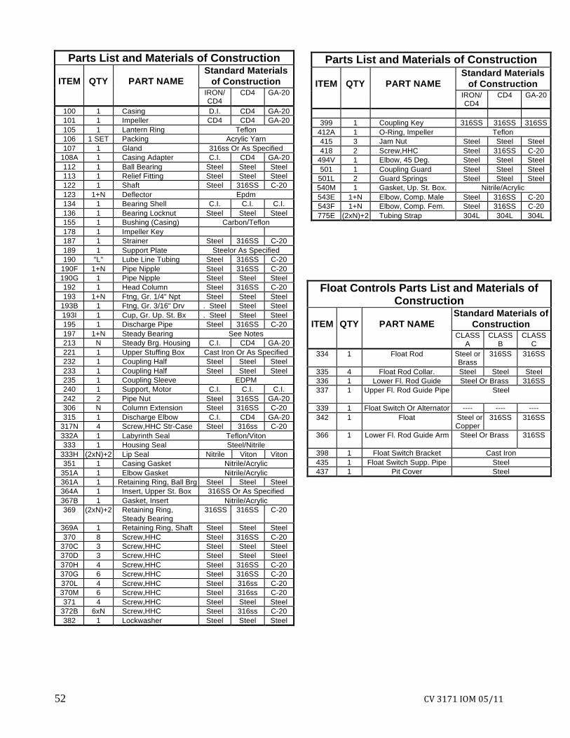
Parts List and Materials of Construction
ITEM
QTY
PART NAME Standard Materials
of Construction IRON/
CD4 CD4 GA-20
100 1 Casing D.I. CD4 GA-20 101 1 Impeller CD4 CD4 GA-20 105 1 Lantern Ring Teflon 106 1 SET Packing Acrylic Yarn 107 1 Gland 316ss Or As Specified
108A 1 Casing Adapter C.I. CD4 GA-20 112 1 Ball Bearing Steel Steel Steel 113 1 Relief Fitting Steel Steel Steel 122 1 Shaft Steel 316SS C-20 123 1+N Deflector Epdm 134 1 Bearing Shell C.I. C.I. C.I. 136 1 Bearing Locknut Steel Steel Steel 155 1 Bushing (Casing) Carbon/Teflon 178 1 Impeller Key 187 1 Strainer Steel 316SS C-20 189 1 Support Plate Steelor As Specified 190 "L" Lube Line Tubing Steel 316SS C-20
190F 1+N Pipe Nipple Steel 316SS C-20 190G 1 Pipe Nipple Steel Steel Steel 192 1 Head Column Steel 316SS C-20 193 1+N Ftng, Gr. 1/4" Npt Steel Steel Steel
193B 1 Ftng, Gr. 3/16" Drv . Steel Steel Steel 193I 1 Cup, Gr. Up. St. Bx . Steel Steel Steel 195 1 Discharge Pipe Steel 316SS C-20 197 1+N Steady Bearing See Notes 213 N Steady Brg. Housing C.I. CD4 GA-20 221 1 Upper Stuffing Box Cast Iron Or As Specified 232 1 Coupling Half Steel Steel Steel 233 1 Coupling Half Steel Steel Steel 235 1 Coupling Sleeve EDPM 240 1 Support, Motor C.I. C.I. C.I. 242 2 Pipe Nut Steel 316SS GA-20 306 N Column Extension Steel 316SS C-20 315 1 Discharge Elbow C.I. CD4 GA-20
317N 4 Screw,HHC Str-Case Steel 316ss C-20 332A 1 Labyrinth Seal Teflon/Viton 333 1 Housing Seal Steel/Nitrile
333H (2xN)+2 Lip Seal Nitrile Viton Viton 351 1 Casing Gasket Nitrile/Acrylic
351A 1 Elbow Gasket Nitrile/Acrylic 361A 1 Retaining Ring, Ball Brg Steel Steel Steel 364A 1 Insert, Upper St. Box 316SS Or As Specified 367B 1 Gasket, Insert Nitrile/Acrylic 369 (2xN)+2 Retaining Ring,
Steady Bearing 316SS 316SS C-20
369A 1 Retaining Ring, Shaft Steel Steel Steel 370 8 Screw,HHC Steel 316SS C-20
370C 3 Screw,HHC Steel Steel Steel 370D 3 Screw,HHC Steel Steel Steel 370H 4 Screw,HHC Steel 316SS C-20 370G 6 Screw,HHC Steel 316SS C-20 370L 4 Screw,HHC Steel 316ss C-20 370M 6 Screw,HHC Steel 316ss C-20 371 4 Screw,HHC Steel Steel Steel
372B 6xN Screw,HHC Steel 316ss C-20 382 1 Lockwasher Steel Steel Steel
Float Controls Parts List and Materials of Construction
ITEM
QTY
PART NAME
Standard Materials of Construction
CLASS A
CLASS B
CLASS C
334 1 Float Rod Steel or Brass
316SS 316SS
335 4 Float Rod Collar. Steel Steel Steel 336 1 Lower Fl. Rod Guide Steel Or Brass 316SS 337 1 Upper Fl. Rod Guide Pipe Steel
339 1 Float Switch Or Alternator ---- ---- ---- 342 1 Float Steel or
Copper 316SS 316SS
366 1 Lower Fl. Rod Guide Arm Steel Or Brass
316SS
398 1 Float Switch Bracket Cast Iron 435 1 Float Switch Supp. Pipe Steel 437 1 Pit Cover Steel
Parts List and Materials of Construction
ITEM
QTY
PART NAME Standard Materials
of Construction IRON/
CD4 CD4 GA-20
399 1 Coupling Key 316SS 316SS 316SS
412A 1 O-Ring, Impeller Teflon 415 3 Jam Nut Steel Steel Steel 418 2 Screw,HHC Steel 316SS C-20
494V 1 Elbow, 45 Deg. Steel Steel Steel 501 1 Coupling Guard Steel Steel Steel
501L 2 Guard Springs Steel Steel Steel 540M 1 Gasket, Up. St. Box. Nitrile/Acrylic 543E 1+N Elbow, Comp. Male Steel 316SS C-20 543F 1+N Elbow, Comp. Fem. Steel 316SS C-20 775E (2xN)+2 Tubing Strap 304L 304L 304L
HOW TO ORDER PARTS
When ordering parts call
1-800-446-8537 or your local Goulds Representative
EMERGENCY SERVICE
Emergency parts service is available 24 hours a day, 365 days/year
Call 1-800-446-8537
Form No. I3171CV Rev. 05/11
© copyright 2006 Goulds Pumps, Incorporated a subsidiary of ITT Corporation