modeling approaches for switching converters - unicampantenor/pdffiles/spiazzi.pdf · modeling...
TRANSCRIPT

Modeling approaches for switching converters 1/72
Modeling approaches for switching converters
by
Giorgio Spiazzi
University of Padova – ITALY
Dept. of Information Engineering – DEI

Modeling approaches for switching converters 2/72
•• Switching cell average model in continuous conduction Switching cell average model in continuous conduction mode (CCM)mode (CCM)
•• Switching cell average model in discontinuous Switching cell average model in discontinuous conduction mode (DCM): firstconduction mode (DCM): first--order modelorder model
PWM convertersPWM converters
Summary of the presentation

Modeling approaches for switching converters 3/72
Basic DC-DC Converter topologies: 2°order
ug
+uo
+
-
DS L
is iL
iD Ro
BuckBuck
ug
+uo
+
-
DS
L
iL iD
iS Ro
BoostBoost
ug
+uo+
-DS
L
is iD
iL Ro BuckBuck--BoostBoost

Modeling approaches for switching converters 4/72
Basic DC-DC Converter topologies: 4°order
ug
+uo+
-DS
L1
i1 i2
Ro
+uC
Co
L2C1
-uS
+uD
+
-CukCuk
ug
+uo
+
-
D
SL1
i1 iD
Ro
+uC
CoL2
C1
-uS
+ uD+-
i2SEPICSEPIC

Modeling approaches for switching converters 5/72
iDiDiLio
iSiLiSig
Ug+UoUoUgUon+ Uoff
UoUo-UgUoUoff
UgUgUg-UoUon
Buck-boostBoostBuck
a p
c
n
DSL
+
-
Uon
is
+
-
Uoff
iD
iL
Commutation Cell for 2°order converters
22°° order converters can be order converters can be described by a unique described by a unique commutation cell: commutation cell:

Modeling approaches for switching converters 6/72
Averaging
( ) ( )∫−
ττ=t
Ttss
dxT1
txMoving average:
Example: instantaneous and average inductor Example: instantaneous and average inductor current in transient condition current in transient condition
2.8 2.9 3 3.1 [ms]5
6
7
8
9
10
11
[A]
iL
iL
Modeling approaches for switching converters 7/72
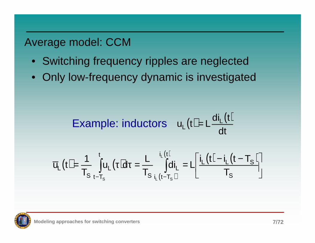
Average model: CCM
• Switching frequency ripples are neglected
• Only low-frequency dynamic is investigated
( ) ( )( )
( ) ( ) ( )
−−==ττ= ∫∫−− S
SLLti
TtiL
S
t
TtL
SL T
TtitiLdi
TL
duT1
tuL
SLS
Example: inductorsExample: inductors ( ) ( )dt
tdiLtu L
L =

Modeling approaches for switching converters 8/72
Average model: CCM
( ) ( )( )
( )( ) ( ) ( ) ( )tz,tywithd,tfz,y,td,tft
z
y
t
t
β=α=ττ=φ=ττ=φ ∫∫β
α
( ) ( )( )
( )( )( ) ( ) ( )( ) ( )
dttd
t,tfdt
tdt,tfd
dt,tdf
dttd t
t
ββ+αα−ττ=φ∫
β
α
( ) ( )dt
tidLtu L
L =
( ) ( ) ?diT1
dtd
dttid t
TtL
S
L
S
=
ττ= ∫
−
( ) ( ) ( )S
SLLL
TTtiti
dttid −−=
Modeling approaches for switching converters 9/72
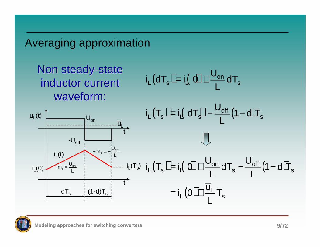
Averaging approximation
t
tdTs
iL(t)
(1-d)Ts
Uon
-Uoff
uL(t)
LU
m on1 =
LU
m off2 −=−
iL(Ts)iL(0)
Lu( ) ( ) ( ) s
offsLsL Td1
LU
dTiTi −−=
( ) ( ) son
LsL dTL
U0idTi +=
( ) ( ) ( )
( ) sL
L
soff
son
LsL
TLu
0i
Td1L
UdT
LU
0iTi
+=
−−+=
Non steadyNon steady--state state inductor current inductor current
waveform:waveform:

Modeling approaches for switching converters 10/72
Averaging
•• Reactive element voltageReactive element voltage--current relations current relations remain valid also for average quantities;remain valid also for average quantities;
•• for inductors, the current variation in a switching for inductors, the current variation in a switching period can be calculated by integrating their period can be calculated by integrating their average voltage;average voltage;
•• for capacitors, the voltage variation in a for capacitors, the voltage variation in a switching period can be calculated by integrating switching period can be calculated by integrating their average current.their average current.
Modeling approaches for switching converters 11/72
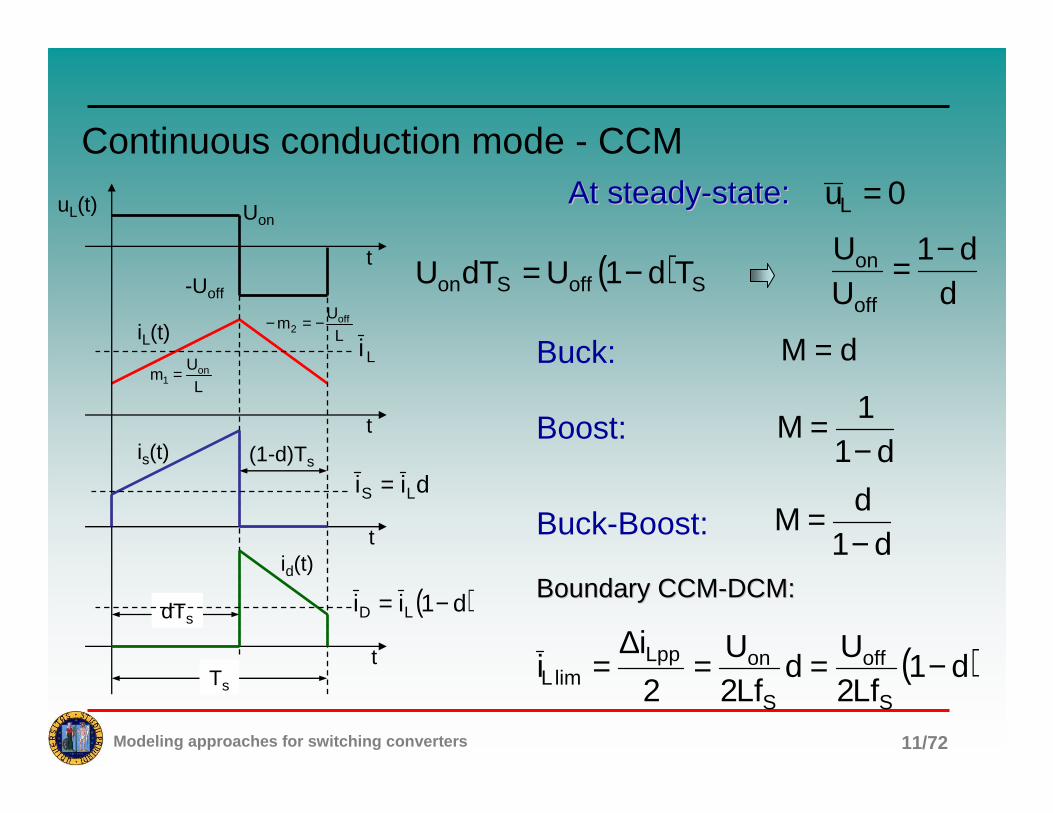
Continuous conduction mode - CCM
( ) SoffSon Td1UdTU −=d
d1UU
off
on −=
At steadyAt steady--state:state:
t
t
dTs
Ts
t
t
iL(t)
is(t)
id(t)
(1-d)Ts
Uon
-Uoff
uL(t)
LU
m on1 =
LU
m off2 −=−
( )d1ii LD −=
dii LS =
Li
0uL =
Buck: dM =
Boost:d1
1M
−=
Buck-Boost:d1
dM
−=
( )d1Lf2
Ud
Lf2U
2
ii
S
off
S
onLpplimL −==
∆=
Boundary CCMBoundary CCM--DCM:DCM:
Modeling approaches for switching converters 12/72
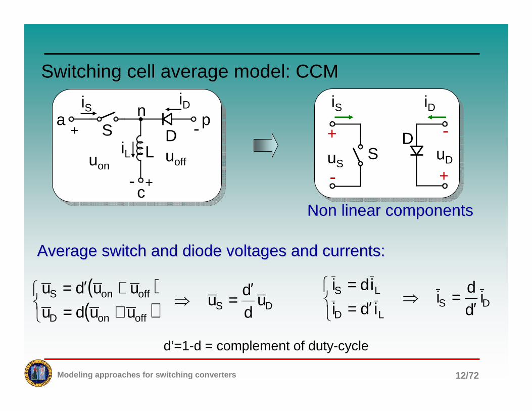
Switching cell average model: CCM
( )( ) DS
offonD
offonS udd
uuudu
uudu ′=⇒
+=+′=
DSLD
LS idd
iidi
idi
′=⇒
′==
a p
c
n
DSL
+
-uon
iS
+
-
uoff
iD
iL
d’=1-d = complement of duty-cycle
DS
iS iD
uD
- +
-uS
+
Non linear componentsNon linear components
Average switch and diode voltages and currents:Average switch and diode voltages and currents:

Modeling approaches for switching converters 13/72
Switching cell average model: CCM
+
- +
-d’:d
Du
Si Di
SuD
S
iS iD
uD
- +
-uS
+
( )( ) DS
offonD
offonS udd
uuudu
uudu ′=⇒
+=+′=
DSLD
LS idd
iidi
idi
′=⇒
′==
+ +
Dudd′
Sidd′
Su
Di
- +
-
Du
Si
d’=1-d = complement of duty-cycle

Modeling approaches for switching converters 14/72
Switching cell average model: CCM
• The non-linear components (switch and diode) are replaced by controlled voltage and current generators representing the relations between average voltage and currents;
• These controlled voltage and current generators can be substituted by an ideal transformer with a suitable equivalent turn ratio.
Modeling approaches for switching converters 15/72
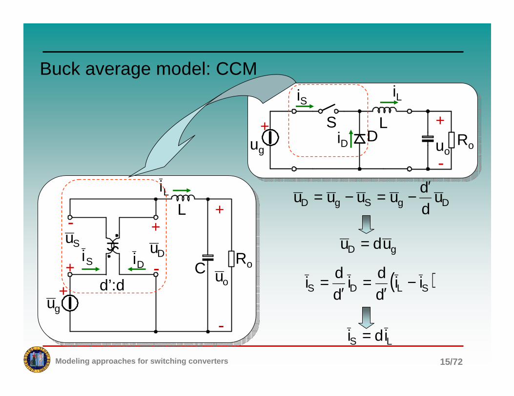
Buck average model: CCM
DgSgD udd
uuuu′
−=−=
gD udu =
( )SLDS iidd
idd
i −′
=′
=
LS idi =
+
+
-
d’:d
L
Ro
+
-+
-
DuSi Di
Su
Li
ou
gu
C
ug
+uo
+
-
DS L
iS iL
iD Roug

Modeling approaches for switching converters 16/72
Buck average model (alternative approach): CCM
D
S
ig iL
ug uD
+
-
+
-
Switching Switching cellcell
Independent variables: Independent variables: uugg, , iiLL
Dependent variables: Dependent variables: uuDD, , iigg
ug
+uo
+
-
DS L
iS iL
iD Ro

Modeling approaches for switching converters 17/72
Buck average model (alternative approach): CCM
D
S
ig iL
ug uD
+
-
+
-
+
-
+
-
1:d
gu
Ligi
Du
AveragingAveraging + +Lid
gudgu
Li
-
+
-Du
gi

Modeling approaches for switching converters 18/72
Buck average model: CCM
−==
−==
o
oLC
C
ogLL
Ru
iidt
udC
uududt
idL
L
C
Lid
gudougu Ro
Li
+ +
-
+
-

Modeling approaches for switching converters 19/72
Boost average model: CCM
+
+
-
d’:d
L
Ro
+
- +
-
DuSi DiSu
Li
ou
gu
C
SoDoS udd
uuuu′
−=−=
oS udu ′=
( )DLSD iidd
idd
i −′
=′
=
LD idi ′=
ug
+uo
+
-
DS
L
iL iD
iS Ro

Modeling approaches for switching converters 20/72
Boost average model (alternative approach): CCM
Switching Switching cellcell
Independent variables: Independent variables: uuoo, , iiLL
Dependent variables: Dependent variables: uuSS, , iiDD
DS
iL iD
uS uo
+
-
+
-
ug
+uo
+
-
DS
L
iL iD
iS Ro

Modeling approaches for switching converters 21/72
Boost average model (alternative approach): CCM
++ Lid′
oud′ou
Li
-
DS
iL iD
uS uo
+
-
+
-
+
-
+
-
d’:1
ou
Li Di
Su

Modeling approaches for switching converters 22/72
Boost average model: CCM
−′==
′−==
o
oLC
C
ogLL
Ru
ididt
udC
uduudt
idL
LC
Li
oud′ougu Ro
Lid′
+ +
-
+
-
d’:1

Modeling approaches for switching converters 23/72
Buck-Boost average model: CCM
( )ogD uudu +=
( )DLSD iidd
idd
i −′
=′
=
LD idi ′=
( )ogS uudu +′=
LS idi =
ug
+uo+
-DS
L
iS iD
iL Ro
+
+
-d’:d
L
Ro
+
- +
-Du
Si Di
Su
Liou
guC
oDoDSg uud1
uuuu −=−+=

Modeling approaches for switching converters 24/72
Buck-Boost average model: CCM
+
+
-d’:d
L
Ro
+
- +
-Du
Si Di
Su
Liou
guC
( )ogD uudu +=
−′==
′−=−==
o
oLC
C
ogoDLL
Ru
ididt
udC
ududuuudt
idL
+ +
-
LRo
+ +
Si Li
ouguCLid′
Lid gud oud′
Di

Modeling approaches for switching converters 25/72
Buck-Boost equivalent average model: CCM
+ +
-
LRo
+ +
Si Li
ouguCLid′
Lid gud oud′
Di
+ +
-
LRo
+
Si Li
ouguC
Di1:d d’:1
}
{
BoostBoost
BuckBuck

Modeling approaches for switching converters 26/72
Cuk average model: CCM
DS
iS iD
uD
- +
-uS
+DS
CD
CS udd
uudu
udu ′=⇒
=′=
( )( ) DS
21D
21S idd
iiidi
iidi′
=⇒
+′=+=
ug
+uo+
-DS
L1
i1 i2
Ro
+uC
Co
L2C1
-uS
+uD
+
-
Switching cellSwitching cell

Modeling approaches for switching converters 27/72
Cuk average model: CCM
+
+
-Ro
+1i
ougu
2i
d’:d
L1
Co
L2
C1
Cu
-
+
+
-
Su Du
−=
−′=
−=
′−=
o
o2
oo
21C
1
oC2
2
Cg1
1
Ru
idt
udC
ididdt
udC
uuddt
idL
ududt
idL

Modeling approaches for switching converters 28/72
Cuk average model: CCM
+ +
-Ro
+
1i
ougu
2i
L1
CoC1Cud
L2+1id′
Cud′
+Cu
2id
+ +
-Ro
+
1i
ougu
2i
L1
CoC1
L2
1id′
Cu
2id
d’:1 1:d
}
{
BoostBoost
BuckBuck

Modeling approaches for switching converters 29/72
SEPIC average model: CCM
DS
is iD
uD
- +
-uS
+
( )( ) DS
oCD
oCS udd
uuudu
uudu ′=⇒
+=+′=
( )( ) DS
21D
21S idd
iiidi
iidi′
=⇒
+′=+=
ug
+uo
+
-
D
SL1
i1 iD
Ro
+uC
CoL2
C1
-uS
+ uD+-
i2
Switching cellSwitching cell

Modeling approaches for switching converters 30/72
SEPIC average model: CCM
+ +
-Ro
+1i
ougu
2i
d’:d
L1
CoL2
C1
Cu Di
-
+
+
-
Su Du( )
( )
−+′=
−′=
′−=
+′−=
o
o21
oo
21C
1
oC2
2
oCg1
1
Ru
iiddt
udC
ididdt
udC
ududdt
idL
uududt
idL

Modeling approaches for switching converters 31/72
SEPIC average model: CCM
+ +
-Ro
+
1i
ou
gu
2i
L1Co
L2
C1 Cu
Di
+ +
+
+Cud′
oud′
1id′
Cud oud′
2id
1id′
2id′
Alternative approachAlternative approach

Modeling approaches for switching converters 32/72
Model perturbation
Generic voltage or current:Generic voltage or current: xXx +=
YxyXXYyx ++≈⋅
Xx <<SmallSmall--signal approximation:signal approximation:
Examples:
( )( ) LLLLLL IdiDDIiIdDid ++≈++=
( )( ) gggggg UduDDUuUdDud ++≈++=
Product of variables:Product of variables:

Modeling approaches for switching converters 33/72
General switching cell: DC and small-signal model
+
- +
-d’:d
Du
Si Di
Su
( ) ( ) DDDSSS UduUDUduUD −+′≈++
( )DDDS
SS uUDD
DUU
duU +′
≈
+++{
Su{
Du
a p
c
n
DSL
+
-uon
iS
+
-
uoff
iD
iL
At steadyAt steady--state:state:
0uL =
====
offDD
onSS
UUu
UUu
DDU
DD
1DU
UU
1DU
DUU SS
S
DSDS
′=
′
+=
+=+

Modeling approaches for switching converters 34/72
General switching cell: DC and small-signal model
+
- +
-d’:d
Du
Si Di
Su
( ) ( ) DDDSSS IdiIDIdiID ++≈−+′
+
- +
-
D’:D
Du
Si Di
Su
+d
DDUS
′ dDD
ID′
( )
+−+′
≈+D
IIdiI
DD
iI DSSSDD{
Di{
Si

Modeling approaches for switching converters 35/72
Buck switching cell: DC and small-signal model
+=+=
dUuDu
dIiDi
ggD
LLg+
-
+
-
1:d
gu
Ligi
Du
dUg
+
-
+
-1:D
Du
gi Li
gu
+
dIL
Perturbation and linearization:Perturbation and linearization:

Modeling approaches for switching converters 36/72
Buck DC and small-signal model
LC
ougu Ro
Li
+ +
-
dUg
1:D
+
dIL
gi
( ) ( )( )
2o
2
o
goud
sQ
s1
U
sDsU
sG
ω+
ω+
==
LC
RQLC1
oo ==ω
DutyDuty--cycle to output voltage transfer function:cycle to output voltage transfer function:

Modeling approaches for switching converters 37/72
Boost switching cell: DC and small-signal model
−′=−′=
dUuDu
dIiDi
ooS
LLD
dUo
+
-
+
-D’:1
ou
Li Di
Su
+
dIL
+
-
+
-
d’:1
ou
Li Di
Su
Perturbation and linearization:Perturbation and linearization:

Modeling approaches for switching converters 38/72
Boost DC and small-signal model
DutyDuty--cycle to output voltage transfer function:cycle to output voltage transfer function:
LC
ougu Ro
Di
+ +
-
+dUo
D’:1
Li
dIL
( )222
o
2
o2gud
LCMsMRL
s1
MRL
s1MUsG
++
−=
RHP zero

Modeling approaches for switching converters 39/72
Boost small-signal model: CCM
1
0t
Normalized output voltage response to a Normalized output voltage response to a dutyduty--cycle step change:cycle step change:
The output voltage initially The output voltage initially moves in the wrong directionmoves in the wrong direction

Modeling approaches for switching converters 40/72
Buck-Boost DC and small-signal model
+
- +
-
D’:D
Du
Si Di
Su
+d
DDUS
′ dDD
ID′
+
+
-
L
Ro
Liou
guC

Modeling approaches for switching converters 41/72
Buck-Boost DC and small-signal model
DutyDuty--cycle to output voltage transfer function:cycle to output voltage transfer function:RHP zero
( ) ( )( )
( ) ( )222
o
o2gud
M1LCsM1RL
s1
M1MRL
s1M1UsG
++++
+−+=
+ +
-
LRo
Si Li
ouguC
Di+
dUo
D’:1dIL
dUg
1:D
+
dIL

Modeling approaches for switching converters 42/72
Cuk DC and small-signal model
D’:D
1i 2i
+d
DDUS
′ dDD
ID′
+
+
-Ro
+
ouguL1
Co
C1
L2
Cu
+
+
-Ro
+1i
ougu
2i
d’:d
L1
Co
L2
C1
Cu
-
+
+
-
Su Du

Modeling approaches for switching converters 43/72
Cuk DC and small-signal model
+ +
-Roougu
+dUC
D’:1dI1
dUC
1:D
+
dI2Cu+
C1
1i 2i
L1
Co
L2
Alternative approachAlternative approach

Modeling approaches for switching converters 44/72
SEPIC DC and small-signal model
D’:D
+d
DDUS
′ dDD
ID′
1i
+gu
L1+
-RoouCo
+C1
Cu
2iL2

Modeling approaches for switching converters 45/72
Discontinuous conduction mode - DCM
t
t
dTs
Ts
t
t
iL(t)
is(t)
id(t)
(d’Ts
Uon
-Uoff
uL(t)
LU
m on1 =
LU
m off2 −=−
Di
Si
Li
SoffSon TdudTu ′=
dd
uu
off
on ′=
( )
+=′+=
off
onon
S
2Lpk
L uu
1uLf2d
dd2
ii
off
2on
S
2Lpk
D uu
Lf2d
d2
ii =′=
onS
2Lpk
S uLf2d
d2
ii ==
At steady-state:
0uL =

Modeling approaches for switching converters 46/72
Discontinuous conduction mode - DCM
Buck:Buck:
−== 1M1
ULf2d
iI gS
2
Lo
2oN
dI
1
1M
+=
Boost:Boost:
−==
1M1
ULf2d
iI gS
2
DooN
2
Id
1M +=
M1
ULf2d
iI gS
2
Do ==oN
2
Id
M =BuckBuck--Boost:Boost:
s
gN
N
ooN Lf2
UI,
II
I ==
t
t
dTs
Ts
t
t
iL(t)
is(t)
id(t)
(d’Ts
Uon
-Uoff
uL(t)
LU
m on1 =
LU
m off2 −=−
Di
Si
Li

Modeling approaches for switching converters 47/72
•• The inductor current is always zero at the The inductor current is always zero at the beginning of each switching period;beginning of each switching period;
•• this loss of the memory effect justifies the this loss of the memory effect justifies the statement that the inductor current is no more a statement that the inductor current is no more a state variable;state variable;
•• switch and diode are replaced by non linear switch and diode are replaced by non linear controlled current generatorscontrolled current generators
First order average models - DCM

Modeling approaches for switching converters 48/72
First order average models - DCM
a p
c
n
DSL
+
-
is
+
-
iD
iL
a p
c
DiSi
Li
onu offu
Inductor average voltage is always Inductor average voltage is always zero in a switching period! zero in a switching period! (?)(?)
t
t
dTs
Ts
t
t
iL(t)
is(t)
id(t)
(d’Ts
Uon
-Uoff
uL(t)
LU
m on1 =
LU
m off2 −=−
Di
Si
Li

Modeling approaches for switching converters 49/72
Buck average model: DCM
uL
LCD
S+
-
ug uo
+
-
Io
+ -
Ro
CLi ougu
oi
gi

Modeling approaches for switching converters 50/72
Buck small-signal model: DCM
dkugugddf
uuf
uuf
i iorgioo
gg
g ++=∂∂+
∂∂+
∂∂=
dkugugddh
uuh
uuh
i ooogfoo
gg
L +−=∂∂+
∂∂+
∂∂=
( ) ( )d,u,uhu
uuu
Lf2d
i ogo
gog
S
2
L =
−=
( ) ( )d,u,ufuuLf2d
ii ogogS
2
Sg =−=={AverageAveragequantities:quantities:
{Perturbation:Perturbation:

Modeling approaches for switching converters 51/72
Buck small-signal model: DCM
CLi ougu
oi
Si
Cgu
Li
oudko
dk i orug
gfug ogig
Si
oR
First order modelFirst order model

Modeling approaches for switching converters 52/72
Boost small-signal model: DCM
CDi ougu
oi
Li
Cgu
Di
oudko
dk i orug
gfug ogig
Li
oR
−=
go
og
S
2
L uuu
uLf2d
i
go
2g
S
2
D uu
u
Lf2d
i−
=

Modeling approaches for switching converters 53/72
Buck-Boost small-signal model: DCM
CDi ougu
oi
Si
Cgu
Di
oudko
dk i orug
gfug ogig
Si
oR
o
2g
S
2
D u
u
Lf2d
i =
gS
2
S uLf2d
i =

Modeling approaches for switching converters 54/72
Full order average models: DCM
t
t=0
t
t
t
t
t
DTs
D’Ts
Li
LL ii +
sTd
sTd′′
i∆
( )tiL
tS
tD
SS tt +
DD tt +
t
St
Dt
Ts
t
( ) { } ( )
se1
TdL
uu
dteidtetiisI
s
s
TDs
soffon
TD
0
st
0
stLLL
′−
′−
∞+−
−+=
∆=== ∫∫L
( ) { } ( )
s
TdsTd
0
st
0
stSS
Tds
e1dte
dtetttsD
ss
≈−==
==
−−
∞+−
∫
∫L
( ) ( )( )
( )
′−′+==
′−
s
TDs
s
offonLid TDs
e1Lf
DuusD
sIsG
s
Impulsive perturbation:Impulsive perturbation:
Response to impulsive perturbation:Response to impulsive perturbation:

Modeling approaches for switching converters 55/72
Full order average models: DCM
t
t=0
t
t
t
t
t
DTs
D’Ts
Li
LL ii +
sTd
sTd′′
i∆
( )tiL
tS
tD
SS tt +
DD tt +
t
St
Dt
Ts
t
First order First order PadPadééapproximation:approximation:
′+
′−
≈′−
2TDs
1
2TDs
1e
s
s
TDs s
( ) ( )
′+
′+≈
2TDs
1
1Lf
DuusG
ss
offonid
Df
fDf2 s
ps
p ′π=⇒
′=ω
( ) ( )( )
( )
′−′+==
′−
s
TDs
s
offonLid TDs
e1Lf
DuusD
sIsG
s

Modeling approaches for switching converters 56/72
Full order average models: DCM
t
t=0
t
t
t
t
t
DTs
D’Ts
Li
LL ii +
sTd
sTd′′
i∆
( )tiL
tS
tD
SS tt +
DD tt +
t
St
Dt
Ts
t
Overall dOverall d’’ perturbation:perturbation:
duu
1du
iLTd
off
on
offs
+=′′⇒
∆=′′
duu
dddoff
on=−′′=′ WRONG!
( )sssD TDtTd)t(Tdt ′−δ⋅′′+δ⋅−=
Dirac functionDirac function
( ) { } ( ) ( ) sTDs
off
onD esD
uu
1sDtsD ′−⋅
++−==′ L

Modeling approaches for switching converters 57/72
Full order average models: DCM
t
t=0
t
t
t
t
t
DTs
D’Ts
Li
LL ii +
sTd
sTd′′
i∆
( )tiL
tS
tD
SS tt +
DD tt +
t
St
Dt
Ts
t
Inductor current perturbation:Inductor current perturbation:
( )( )
sTDs
off
on euu
11sDsD ′−
++−=
′
offonL udud
dt
idL ′−=
( ) ( ) ( ) offonL usDusDsIsL ′−=
( ) ( )( )
( )
′−′+==
′−
s
TDs
s
offonLid TDs
e1Lf
DuusD
sIsG
s

Modeling approaches for switching converters 58/72
Full order average models: DCM
a
pcn
DS
L
iL
a
pcnL
iL
ia
ip
a
pcnL
iLia
uD+ The switch is replaced by a The switch is replaced by a controlled current generator controlled current generator
while the diode is replaced by a while the diode is replaced by a controlled voltage generatorcontrolled voltage generator

Modeling approaches for switching converters 59/72
Full order average models: DCM
( )
=
′+=
di21
i
ddi21
i
Lpa
LpL
ddd
ii La ′+= ( ) ( )dd1uduuu offoffonD ′−−++=
( ) dud
iLf2dddd
Lf2u
ion
Ls
s
onL −=′⇒′+=
t0
iLpiL
tTs0 dTs (d+d’)Ts
uDoffon uu +
offu
ia
a
pcnL
iLia
uD+

Modeling approaches for switching converters 60/72
Example: boost in DCM
a
pcnL
iLia
uD+
( )( )dd1uuduu gooD ′−−−+=
dud
iLf2d
g
Ls −=′
( )( )[ ]
Ldu
idf2
uu
1
dd1uuduuuL1
dt
id
oL
s
g
o
gooogL
+
−=
=′−−−++−=
o
o
s
g2
L
o
oaL
o
CRu
LCf2
ud
C
i
Ru
iiC1
dtud −−=
−−=
( ) ( )( )
( )
+−+
−+
=
+++++
+−=
o
oo
s
g2
LLo
ooLL
s
g
ooL
CRuU
LCf2
UdD
C
iI
dtud
LdDuU
iIdD
f2U
uU1
dt
id
DutyDuty--cycle perturbation:cycle perturbation:

Modeling approaches for switching converters 61/72
Example: boost in DCM( )
−−=
−+−=
o
o
s
gLo
oo
soL
L
CRu
dLCf
DU
C
i
dtud
uDRMf2
dLU2
iM1Df2
dt
id
( ) ( )( ) ( ) ( )
ω+
ω+
ω−
≈−+
−++
−==
pAFpBF
zB
o
ss
o
2
s
s
goud
s1
s1
s1
K
CDR1M2f2
D1Mf2
CR1
ss
sDf2
LCf
DU
sDsU
sG
−−=ω1M1M2
CR1
opHF
SmallSmall--signal linear model:signal linear model:
( )D
1Mf2 spLF
−=ωDf2 s
z =ω( )
k1MM
1M2
U2K g
B−
−=
The same as first order model:The same as first order model:

Modeling approaches for switching converters 62/72
Example: boost in DCM
a) Full order modelb) First order model
10-1
[dB]
-60
-20
-30
-40
-50
( )( ) dBud
ud
0GjG ω
a)
b)
10-210-310-4
-10
100
[deg]
-180
-30
-60
-90
-120
( )ω∠ jGud
a)
b)
-150
10-1
sff10-210-310-4 100
sff
ControlControl--toto--output transfer functionoutput transfer function

Modeling approaches for switching converters 63/72
State-Space averaging (SSA): CCM
Interval Interval dTdTss::
=+=
xCy
uBxAx
1
11&
State, input and output State, input and output variable vector:variable vector:
=C
L
u
ix
=o
g
i
uu
∈∈
=off
on
tt0
tt1)t(q
( ) ( )[ ]( )
⋅+=⋅−+=⋅++=⋅−+−++=
qGxCqxCCxCy
qFuBxAquBBxAAuBxAx
2212
22212122&
Switching function:Switching function:
⋅+=⋅++=
qGxCy
qFuBxAx
2
22&Applying moving Applying moving
average operator:average operator: xx && =
=+=
xCy
uBxAx
2
22&Interval (1Interval (1--d)Td)Tss::
=
g
o
i
uy

Modeling approaches for switching converters 64/72
State-Space averaging (SSA): CCM
Hp: linear ripple approximationHp: linear ripple approximation
=+=+=++=
xCdGxCy
uBxAdFuBxAx
2
22&dFqFqF ⋅=⋅=⋅
t
iL
t
Ts0 dTs
t
q
qiL
Li
LL iqqi =
dq =
?qG?,qF =⋅=⋅
t
uC
t
Ts0 dTs
t
q
quC
Cu
CC uqqu =
dq =
Hp: small ripple approximationHp: small ripple approximation
( )d1AdAA 21 −+= ( )d1BdBB 21 −+=dGqGqG ⋅=⋅=⋅
( )d1CdCC 21 −+=

Modeling approaches for switching converters 65/72
State-Space averaging (SSA): CCM
SteadySteady--state solution:state solution:
=−=
⇒
=+= −
xCy
uBAxxCy
uBxA0 1
( ) ( )[ ]( )
+=−+=++=−+−++=
dGxCdXCCxCy
dFuBxAdUBBXAAuBxAx
21
2121&
SmallSmall--signal linear model:signal linear model:
( ) ( ) ( ) ( )( )( ) ( ) ( )
+=+−= −
sDGsXCsY
sDFsUBAsIsX 1

Modeling approaches for switching converters 66/72
Example: boost converter in CCM
=C
L
u
ix guu = ouy =
Interval Interval dTdTss:: Interval (1Interval (1--d)Td)Tss::
=+=
xCy
uBxAx
1
11&
=+=
xCy
uBxAx
2
22&

Modeling approaches for switching converters 67/72
Example: boost converter in CCM
( )
+−
−=
CrR1
0
0Lr
A
C
L
1( )
( ) ( )
+−
+
+−+−
=
CrR1
CrRR
LrRR
LR//rr
A
CC
C
CL
2
+=
C1 rR
R0C
+=
CC2 rR
Rr//RC
==
0L1
BB 21
SteadySteady--state state solution:solution: g
1 UBAx0x −−=⇒=&
′′
==
′′=
=
R
RDUUY
RD
1
R
U
U
IX
go
g
C
L
( )R//rDDrRDR CL2 ′++′=′
( )R//rDDrRD
RDD1
UU
MCL
2
2
g
o
′++′′
⋅′
==
Voltage conversion ratio:Voltage conversion ratio:

Modeling approaches for switching converters 68/72
Example: boost converter in CCM
SmallSmall--signal linear model:signal linear model:
( )( )
( ) ( )
( )( )
( )d
CrRR
LrRrRDR
R
Uu
0L1
u
i
CrR1
CrRRD
LrRRD
LR//rDr
u
i
C
C
C
gg
C
L
CC
C
CL
C
L
+−
++′
′+
+
+−
+′
+′
−′+−
=
&
&
( ) dR
R||rU
u
i
rRR
R||rDy Cg
C
L
CC ′
−
+′=

Modeling approaches for switching converters 69/72
State-Space averaging (SSA): DCM
Applying moving Applying moving average operator:average operator:
xx && =t
iLpiL
d1Ts d2Ts d3Ts
LUon
LUoff−
t
t
t
1
1
1
q1
q2
q3
( ) uBqxAqtx3
1kkk
3
1kkk
+
= ∑∑
==
&
uBdxAdx3
1kkk
3
1kkk
+
≠ ∑∑
==
&
Why?
State variable vector:State variable vector:
=C
L
u
ix

Modeling approaches for switching converters 70/72
State-Space averaging (SSA): DCM
Example:Example: iiLL··qq11t
iLpiL
d1Ts d2Ts d3Ts
LUon
LUoff−
t
1 q1
iLq1
Li
1L1L qiqi ≠
( )21Lpk
L dd2
ii +=
212L
21
2L2
LpkDL2
dd1
qi
ddd
id2
iiiq
+=
+===
211L
21
1L1
LpkSL1 dd
1qi
ddd
id2
iiiq
+=
+===
Hp: linear ripple approximationHp: linear ripple approximation
Corrective termCorrective term

Modeling approaches for switching converters 71/72
State-Space averaging (SSA): DCM
uBdxMAdx3
1kkk
3
1kkk
+
= ∑∑
==
&
3,2,1iuduquq CiCiCi ===
Hp: small ripple approximationHp: small ripple approximation
+=10
0dd
1M
21
M is the correction matrixM is the correction matrix
( ) uBqxAqtx3
1kkk
3
1kkk
+
= ∑∑
==
&

Modeling approaches for switching converters 72/72
State-Space averaging (SSA): DCM
If dIf d33 = 0, i.e. in CCM, we have:= 0, i.e. in CCM, we have:
uBdxMAdx3
1kkk
3
1kkk
+
= ∑∑
==
&
+=10
0dd
1M
21 1on
Ls2 d
u
iLf2d −
δ=
213 dd1d −−=
=10
01M uBdxAdx
2
1kkk
2
1kkk
+
= ∑∑
==
&