models 8500 & 8500m handheld pulse oximetersprnrents.com/manuals/nonin-8500-manual.pdf · the...
TRANSCRIPT
Operator’s Manual
Models 8500 & 8500M Handheld Pulse Oximeters
English


i
About the Manual There are many contraindications, warnings, and cautions throughout this manual. Read them carefully; they are important to the use of the product. The information in this manual has been carefully checked and is believed to be accurate. In the interest of continued product development, NONIN reserves the right to make changes and improvements to this manual and the products it describes at any time, without notice or obligation.
CAUTION! Federal law (USA) restricts this device to sale by or on the
order of a physician. CAUTION! Read this manually carefully before using the Model 8500.
Nonin Medical, Inc. 2605 Fernbrook Lane North
Plymouth, MN 55447-4755 USA
(763) 553-9968 (800) 356-8874 (USA and Canada)
Fax (763) 553-7807 E-mail: [email protected]
www.nonin.com
Authorized EC Representative: MPS, Medical Product Service GmbH
Borngasse 20 D-35619 Braunfels, Germany
References to “NONIN” in this manual shall imply Nonin Medical, Inc. NONIN, nVISION, Flexi-Form, and FlexiWrap are registered trademarks or trademarks of Nonin Medical, Inc. References to “8500” in this manual imply Models 8500 and 8500M. © 2002 Nonin Medical, Inc.

ii
Table of Contents
Precautions for Use .................................................................... 1 Unpacking the Model 8500 ........................................................3 Introduction................................................................................4 Indications for Use ..................................................................................... 4 General Description ................................................................................... 4 Basic Operation..........................................................................5 Installing Batteries....................................................................................... 5 Connecting Sensors .................................................................................... 7 Features .................................................................................... 10 Controls.................................................................................................... 10 Displays .................................................................................................... 15 Printer/Serial Output ............................................................................. 17 Memory Option (8500M Only) ............................................................ 18 Specifications............................................................................20 Service....................................................................................... 21 Warranty ...................................................................................22 Accessories ...............................................................................23 Troubleshooting Guide ............................................................24
Guide to Symbols
Attention: See instructions for use.
Type BF Applied Part (Patient isolation from electric shock)
Canadian Standards Association
UL Underwriters Laboratories
CE Marking indicating conformance to EC directive No. 93/42/EEC concerning medical devices

1
Precautions for Use
Contraindications • Do not use the 8500 in an MRI environment. • Do not use the 8500 in a situation where alarms are required. The
8500 has no alarms.
Warnings • Explosion Hazard. Do not use the 8500 in an explosive atmosphere. • The 8500 is intended only as an adjunct in patient assessment. It
must be used in conjunction with other methods of assessing clinical signs and symptoms.
• Use only NONIN-manufactured pulse oximeter sensors. These sensors are manufactured to meet the accuracy specifications for NONIN Pulse Oximeters. Using other manufacturers’ sensors may cause improper pulse oximeter performance.
• As with all medical devices, carefully route patient cabling to reduce the possibility of patient entanglement or strangulation.
• Check the application site frequently to determine the positioning of the sensor and the circulation and skin sensitivity of the patient. Each patient’s sensitivity to NONIN sensors might vary, depending upon medical status or skin condition.
• Discontinue use of adhesive tape strips if the patient exhibits an allergic reaction to the adhesive material.
• Do not stretch the adhesive tape while applying the sensor. This may cause inaccurate readings or skin blisters.
• General operation of the 8500 might be affected by the presence of an electrosurgical unit (ESU).
• Do not use a damaged sensor.
Cautions • Federal law (USA) restricts this device to sale by or on the order of a
physician. • Read this manual carefully before using the 8500. • Before use, carefully read the package insert provided with the
sensor(s). • The 8500 is intended for spot-checking or monitoring by a health
care professional. Because the 8500 has no audible alarms, international labeling requirements dictate that it be labeled "Not for continuous monitoring."
• The 8500 pulse oximeter is not an apnea monitor.

2
• Verify that all visible indicators illuminate during the startup (initialization) sequence. If any indicator is not lit, do not use the 8500. Contact NONIN Customer Support for repair or replacement.
• The 8500 must be able to measure the pulse properly in order to obtain an accurate SpO2 measurement. Verify that nothing is hindering the pulse measurement before relying on the SpO2 measurement.
• The 8500 might not work on all patients. If you are unable to achieve stable readings, discontinue use.
• The 8500 might misinterpret motion as good pulse quality. Minimize patient motion as much as possible.
• The 8500 is designed to determine the percentage of arterial oxygen saturation of functional hemoglobin. Significant levels of dysfunctional hemoglobin may affect the accuracy of the measurement.
• Cardiogreen and other intravascular dyes, depending on the concentration, might affect the accuracy of the SpO2 measurement.
• Ear Clip and Reflectance pulse oximeter sensors are not recommended for pediatric or neonatal use. The accuracy of these sensors has not been established for pediatric or neonatal use.
• Do not immerse the 8500 or NONIN sensors in liquid. • Do not use caustic or abrasive cleaning agents on the 8500 or on the
sensors. • The 8500 must be repaired only by trained NONIN personnel. • Do not use different types of batteries or mix fully- and partially-
charged batteries at the same time.; battery leakage might result. • Do not remove any covers (except the battery cover) when replacing
batteries. • Follow local ordinances and recycling instructions regarding disposal
or recycling of the device and device components, including batteries. Batteries might leak or explode if used or disposed of improperly.
• Remove the batteries to avoid the risk of leakage if the 8500 will be stored for more than one month.
• This equipment complies with International Standard EN 60601-1-2:1993 for electromagnetic compatibility for medical electrical equipment and/or systems. This standard is designed to provide reasonable protection against harmful interference in a typical medical installation. However, because of the proliferation of radio-frequency transmitting equipment and other sources of electrical noise in healthcare and other environments (for example, cellular phones, electrical appliances), it is possible that high levels of such interference due to close proximity or strength of a source might result in disruption of performance of this device.

3
Unpacking the Model 8500 Confirm that the items listed below are packed with the 8500 Handheld Pulse Oximeter. The 8500 shipment includes:
• 8500 or 8500M Handheld Pulse Oximeter • Operator’s Manual for Models 8500 and 8500M Pulse Oximeter • Six AA batteries • One sensor
If any item on this list is missing or damaged, contact your distributor. Contact the carrier immediately if the shipping carton is damaged.
4
Introduction
Indications for Use The NONIN® 8500 Handheld Pulse Oximeter is indicated for measuring and displaying functional oxygen saturation of arterial hemoglobin (SpO2) and pulse rate for adult, pediatric, and neonatal patients in hospital, ambulatory, home, and EMS (emergency medical service) environments. The 8500 is intended for spot-checking and/or continuous monitoring when attended by a trained healthcare professional.
General Description The Model 8500 is a digital handheld pulse oximeter that displays numeric values for blood oxygen saturation and pulse rate. It typically operates for 100 hours continuously between alkaline battery replacements and requires no routine calibration or maintenance other than battery replacement. The pulse oximeter determines functional oxygen saturation of arterial hemoglobin (SpO2) by measuring the absorption of red and infrared light passing through perfused tissue. Changes in absorption caused by the pulsation of blood in the vascular bed are used to determine oxygen saturation and pulse rate. Oxygen saturation and pulse rate values are displayed by light-emitting diode (LED) digital displays. On each detected pulse, the pulse quality LED blinks. Patient pulse quality signals are graded as good, marginal, or inadequate and are indicated as such by the pulse quality indicator blinking green, yellow, or red, respectively. This simple method gives the user a pulse-by-pulse visual indication of waveform signal quality without requiring complex waveform analyses. The Model 8500 pulse oximeter may be used with a variety of NONIN pulse oximeter sensors. Because the Model 8500 has no patient alarms, SpO2 and pulse rate displays must be observed frequently. A sensor disconnect or malfunction is indicated by a lack of good pulse quality blinking and/or a dash to the left of the SpO2 value on the LED display. When adequate pulse signals are not received, the SpO2 and/or pulse rate numeric values will be replaced by dashes. Low and critically low battery conditions will be indicated by the low battery LED.
5
Basic Operation
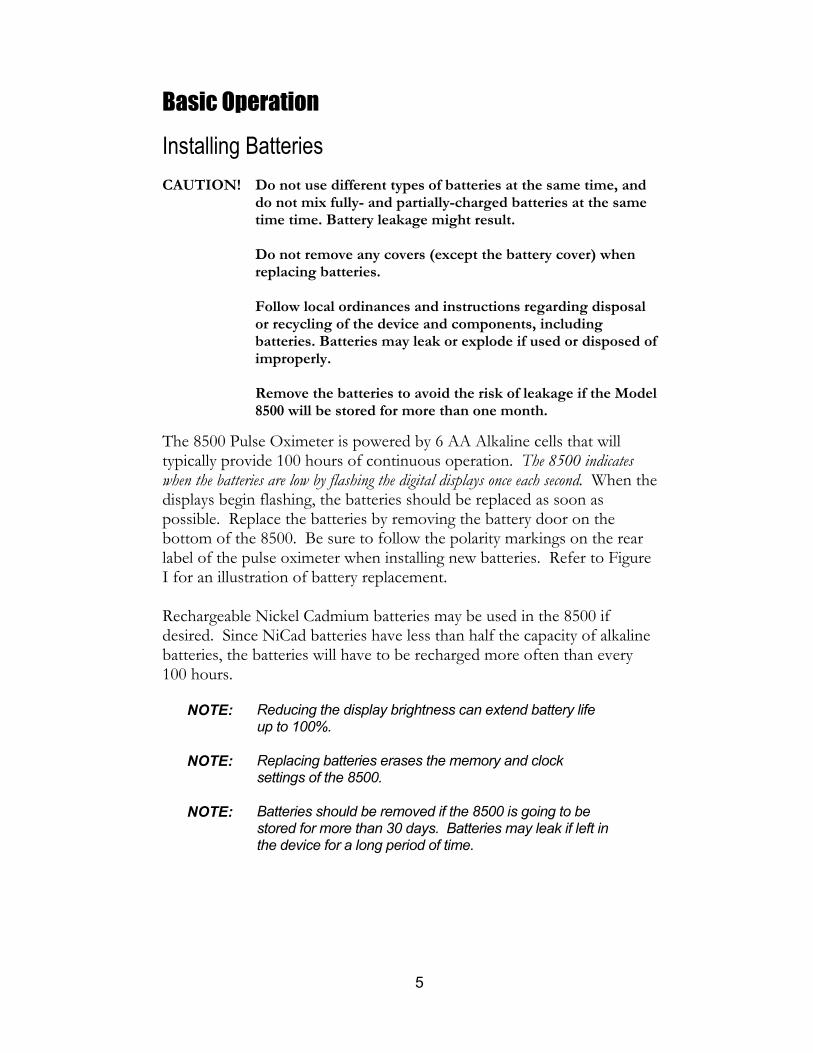
Installing Batteries CAUTION! Do not use different types of batteries at the same time, and
do not mix fully- and partially-charged batteries at the same time time. Battery leakage might result.
Do not remove any covers (except the battery cover) when
replacing batteries. Follow local ordinances and instructions regarding disposal
or recycling of the device and components, including batteries. Batteries may leak or explode if used or disposed of improperly.
Remove the batteries to avoid the risk of leakage if the Model
8500 will be stored for more than one month.
The 8500 Pulse Oximeter is powered by 6 AA Alkaline cells that will typically provide 100 hours of continuous operation. The 8500 indicates when the batteries are low by flashing the digital displays once each second. When the displays begin flashing, the batteries should be replaced as soon as possible. Replace the batteries by removing the battery door on the bottom of the 8500. Be sure to follow the polarity markings on the rear label of the pulse oximeter when installing new batteries. Refer to Figure I for an illustration of battery replacement. Rechargeable Nickel Cadmium batteries may be used in the 8500 if desired. Since NiCad batteries have less than half the capacity of alkaline batteries, the batteries will have to be recharged more often than every 100 hours.
NOTE: Reducing the display brightness can extend battery life
up to 100%. NOTE: Replacing batteries erases the memory and clock
settings of the 8500. NOTE: Batteries should be removed if the 8500 is going to be
stored for more than 30 days. Batteries may leak if left in the device for a long period of time.

6
Figure I: Replacing Batteries in the 8500

7
Connecting Sensors Connect the sensor to its 9-pin mating jack on the top of the 8500 as shown in Figure II. If additional cable length is necessary, connect the Model 8500I Patient Cable between the sensor and the 8500 Pulse Oximeter. Position the appropriate sensor on the patient.
Figure II: Connecting Sensors to the 8500
Turning on the Pulse Oximeter Turn on the Model 8500 by pressing the "" button on the front of the pulse oximeter. Refer to Figure III. When the 8500 is powered on, the SpO2 and ♥ displays will cycle through the following sequence before displaying valid data values:
• " " • time saved in memory in hours and minutes • software revision number • " - - "

8
Figure III: Front View of the 8500
Figure IV: Rear View of the 8500

9
Verifying Operation
CAUTION! The 8500 must be able to measure the pulse properly to obtain accurate SpO2 measurement. Verify that nothing is hindering the pulse measurement before relying on the SpO2 measurement.
Verify that the sensor is properly positioned, and ensure that the system is sensing adequate perfusion by observing that the (perfusion) indicator is blinking green, and the blinking is correlated to the pulse rate for 10 seconds. Should the perfusion light be red or yellow or flashing erratically, reposition the sensor or try a different sensor.
Cleaning the Pulse Oximeter CAUTION! Do not immerse the 8500 in liquid, and do not use caustic or
abrasive cleaning agents.
The 8500 Pulse Oximeter may be cleaned with a mild detergent and a soft cloth or with an isopropyl alcohol wipe. Allow enough time for the 8500 to dry thoroughly before reusing.

10
Features
Controls All functions of the 8500 are controlled by switches found on the front of the unit. Refer to Figure III for an illustration of these switches.
Power Pressing the ON switch ("") causes power to be applied to all internal circuitry. Pressing the OFF switch ("∅") causes power to be removed from the displays and puts the pulse oximetry circuitry into a low power standby mode. In order to conserve battery life, the 8500 automatically powers off after 10 minutes of inactivity. Inactivity is indicated by dashes on the displays and is caused by:
• no sensor connected to the pulse oximeter • patient pulse too low • sensor not attached to a patient
Each time a reading is displayed, the 10 minute timer is restarted. The "" switch has additional clock and printer mode setting functions when used in conjunction with the " " switch.
Display Brightness The arrow switch (" ") causes the brightness of the digital displays to change. When powered up, the digital display defaults to the maximum brightness. Pressing the " " will advance the brightness to the lowest setting, and each subsequent press will advance the brightness through 8 different settings. The function is circular, which means it will cycle through the entire brightness range and then start at the beginning again. Lower brightness may be used to preserve battery life; higher brightness may be used to view the displays from a distance.
NOTE: Reducing the LED display brightness can extend battery
life up to 100%.
The " " switch has additional clock mode setting functions when used with the "" switch.
11
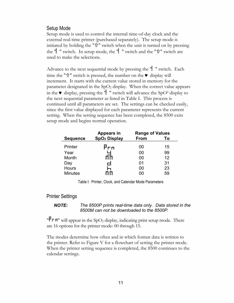
Setup Mode Setup mode is used to control the internal time-of-day clock and the external real-time printer (purchased separately). The setup mode is initiated by holding the " " switch when the unit is turned on by pressing the "" switch. In setup mode, the "" switch and the " " switch are used to make the selections. Advance to the next sequential mode by pressing the "" switch. Each time the " " switch is pressed, the number on the ♥ display will increment. It starts with the current value stored in memory for the parameter designated in the SpO2 display. When the correct value appears in the ♥ display, pressing the "" switch will advance the SpO2 display to the next sequential parameter as listed in Table I. This process is continued until all parameters are set. The settings can be checked easily, since the first value displayed for each parameter represents the current setting. When the setting sequence has been completed, the 8500 exits setup mode and begins normal operation.
Appears in Range of Values Sequence SpO2 Display From To
Printer 00 15 Year 00 99 Month 00 12 Day 01 31 Hours 00 23 Minutes 00 59
Table I: Printer, Clock, and Calendar Mode Parameters
Printer Settings NOTE: The 8500P prints real-time data only. Data stored in the
8500M can not be downloaded to the 8500P.
" " will appear in the SpO2 display, indicating print setup mode. There are 16 options for the printer mode: 00 through 15. The modes determine how often and in which format data is written to the printer. Refer to Figure V for a flowchart of setting the printer mode. When the printer setting sequence is completed, the 8500 continues to the calendar settings.

12
Display
Press Press
Proceed tocalendar setup
DefaultSetting
Press Press
DisplaySpO2
SetupMode
Incrementprintermode
Figure V: Flow Chart for Setting Printer Mode
Printer Mode
Seconds per data
point
Minimum SpO2
printed?*
Touch print
capability?**
00 10 No Yes 01 30 No Yes 02 120 No Yes 03 10 Yes Yes 04 30 Yes Yes 05 120 Yes Yes 15 --- No Yes
* For modes where the minimum SpO2 data is written, there are two lines of data written for each data output. The first line contains the minimum value for SpO2 since the last printout, and the second line contains the current data values. ** The touch print mode enables the user to print out data at any time. This is activated by pressing the "" switch.
Table II: 8500P Printer Modes

13
Calendar Settings
After the printer setting has been determined in the setup mode, " " will appear in the SpO2 display, indicating calendar setup mode for the year. The year may be set to "00" through "99". After selecting the year, the display will show " ," indicating the setup mode for the month. The month may be set to "00" through "12". After selecting the month, the display will show " ," indicating the setup mode for the day of the month. The day may be set to "01" through "31". Refer to Figure VI for a flowchart of setting the calendar. When the calendar setting sequence is completed, the 8500 continues to the clock settings.
NOTE: Setting the month to "00" disables the clock function and
helps conserve battery life.
Display
Press
DefaultSetting
Press
DisplaySpO2
SetupMode
Press
Press
Press
Press
Press
Press
Incrementyear
Press
Incrementmonth
Press
Incrementday
Proceed toclock setup
PressPress
Figure VI: Flow Chart for Setting Calendar

14
Clock Settings After the calendar settings have been determined in the setup mode, " " will appear in the SpO2 display, indicating clock setup mode for the hour. The hour may be set to "00" through "23". After selecting the hour, the display will show " ," indicating the setup mode for the minutes. The minutes may be set to "00" through "59". After selecting the minutes, the display will return to normal operation. Refer to Figure VII for a flowchart of setting the clock.
Display
Press
DefaultSetting
Press
DisplaySpO2
SetupMode
Press
Press
Press
Press
Press
Increment
Press
Increment
hour
Proceed to
minute
normal operation
Figure VII: Flow Chart for Setting Clock
Printer modes determine how often and in which format data is written to the printer. For modes where the minimum SpO2 data is written, two lines of data are written for each data output. The first line contains the minimum value for SpO2 since the last printout, and the second line contains the current data values. Touch print mode enables users to print data at any time by pressing the "" switch.

15
Displays SpO2 Display The left digital display is a 3-digit light emitting diode (LED) digital display that indicates oxygen saturation percentage. Refer to Figure III.
♥ (Pulse Rate) Display The right digital display is a 3-digit LED digital display that indicates pulse rate in pulses per minute. Refer to Figure III.
(Perfusion) Indicator The perfusion indicator (identified by the waveform symbol ) will flash once for each pulse while measuring oxygen saturation. The perfusion indicator changes color to indicate changes in the pulse waveform signal that may affect SpO2 data. The perfusion indicator may blink one of three colors: green, yellow, or red. These colors are similar to the colors of a stoplight such that: Red indicates the pulse amplitude is too small. During red perfusion, SpO2 and pulse rate values are not updated. After ten seconds, values are replaced with dashes, indicating SpO2 measurement is not possible. Yellow indicates the pulse waveform amplitude is marginal or the pulse oximeter has detected artifact. Although SpO2 data is acceptable, corrective measures should be considered to improve sensor placement, change sensor type, or reduce patient movement. Green indicates a good pulse waveform signal and accurate SpO2 data.
CAUTION! The 8500 might interpret motion as good perfusion.

16
Flashing Display The numerical displays will flash once each second if the 8500 determines that a battery low condition exists. Replace all six batteries immediately.
NOTE: Inaccurate SpO2 and/or pulse rate measurement might
result if the 8500 is operated in a low battery condition.
Dash in SpO2 Display If the 8500 determines that a sensor fault exists (sensor disconnect, sensor failure, or sensor dislodgment), a dash (-) appears in the left-most digit of the SpO2 display. The readings displayed will remain unchanged while the sensor fault exists. If the sensor fault is not corrected, dashes will be displayed 10 seconds after the minus sign appears.

17
Printer/Serial Output Both the 8500 and 8500M Hand Held Pulse Oximeters provide output capability to a custom printer via the 9-pin Sub-D connector. This connector serves as a sensor input connector as well as a printer interconnect device. The 9-pin Sub-D connector pin assignments are listed in Table III.
Pin Number Assignment
1 Battery Voltage 2 Infrared Anode, Red Cathode 3 Infrared Cathode, Red Anode 4 Serial Data, TTL Levels 5 Detector Anode 6 Logic Level 7 Cable Shield 8 Coaxial Shield 9 Detector Cathode, +5 V
Table III: Printer/Sensor Interface Assignments
The information from the 8500 in the real-time mode is sent in an ASCII serial format at 9600 baud with 9 data bits, 1 start bit, and 1 stop bit. The data is output at a rate of once per second.
NOTE: The 9th data bit is used for parity in memory playback
mode. In real-time mode, it is always set to the mark condition. Therefore the real-time data may be read as 8 data bits, no parity.
The data printed by the 8500P printer is in the following format:
HH:MM:SS SPO2=XXX HR=YYY
where "HH" represents the hour, "MM" represents the minutes, "SS" represents the seconds, "XXX" represents the SpO2 value, and "YYY" represents the heart rate. SpO2 and heart rate will be displayed as "---" if there is no data available for the data reading.

18
Memory Option (8500M Only) The memory option is identified by the "M" in the model number (i.e. 8500M as opposed to the 8500). This model number is located just above the serial number on the back of the unit. The 8500M Pulse Oximeter can collect and store up to eighteen hours of SpO2 and pulse rate information. The memory in the 8500M functions as an “endless loop.” When memory fills up, the unit begins overwriting the oldest data with the newest. Each time the 8500M is powered up, the current time/date information (if the clock is set properly) is stored in memory to allow quick differentiation of recording sessions. Patient SpO2 and pulse rate are sampled and stored every four seconds. The stored resolution of the oxygen saturation is in 1% increments in the range of 0 to 100 %. The stored pulse rate ranges from 18 to 300 BPM. The stored values have a resolution of 1 BPM from 18 to 200 and a resolution of 2 BPM from 201 to 300. During the printing of the data, the last data recorded is the first data printed. For example, the last four minutes of data recorded would be the first four minutes of printout.
Recording Sessions Each time the 8500M is turned on (except while setting the clock) data is automatically collected.
NOTE: Only recording sessions greater than one minute in length
are kept in memory for later printing.

19
Memory Output Mode
To output the data stored in the memory of the 8500M, start with the unit OFF and then:
1) Hold the " " switch while pressing the "" switch; 2) Release the " " and "" switches when " " is displayed
in the SpO2 and pulse rate LEDs; 3) Observe " XX" will be displayed in the SpO2 and ♥ LEDs; 4) Data is automatically transferred from the memory in
approximately 8 to 10 minutes.
Data is transferred at a rate of 20 minutes of collected data per second. An 18 hour recording session (the maximum memory saved) is transferred in approximately 1 minute. After all the data is transferred, the 8500M should be shut off before collecting new patient data. Patient information is held in memory as long as the batteries are good, so if the memory has to be cleared, remove the battery door for 60 seconds or longer. Outputting the memory does not clear any data from the memory.
NOTE: The memory is cleared each time the batteries are changed.

20
Specifications
1. Oxygen Saturation Range (SpO2)
0 to 100%
2. Pulse Rate Range
18 to 300 Pulses Per Minute
3. Displays Patient Indicator Perfusion LED Digital Displays
3-digit 7-segment LEDs 4. Measurement Wavelengths
Red 660 nanometers Infrared
910 nanometers 5. Accuracy
SpO2 (± 1 Standard Deviation)♦
• 70 - 95% ± 3 digits for neonates using infant or neonatal sensors
• 70 - 100% ± 2 digits for adults using the Finger Clip sensor
• 70 - 100% ± 3 digits for adults using Flex or Reflectance sensors
• 70 - 100% ± 4 digits using Ear Clip sensor
• Below 70% is not specified for all sensors
Pulse Rate
± 3% ± 1 digit
6. Temperature Operating -20 to +50 °C Non-operating
-30 to +50 °C
7. Humidity Operating 10 to 90% non-condensing Non-operating
10 to 95% non-condensing
8. Power Requirements 6 AA alkaline batteries 100 hours typical operation (maximum display brightness) 200 hours typical operation (minimum display brightness)
9. Patient Isolation > 12 MΩ
10. Leakage Current Not applicable
11. Dimensions 3" wide x 6" high x 1" deep 8 cm x 15 cm x 2 cm
12. Weight 10 oz. (280 g) with batteries ♦ Standard Deviation is a statistical measure: up to 32% of the readings may fall outside these limits.

21
Service
CAUTION! The 8500 Handheld Pulse Oximeters must be repaired by trained NONIN personnel only. Any evidence of opening the system, field service by non-NONIN personnel, tampering, or any kind of system misuse or abuse shall void the warranty.
The solid state circuitry within the 8500 requires no periodic maintenance or calibration other than battery replacement. NONIN does not recommend field repair of the 8500 Handheld Pulse Oximeter. The circuit board in the 8500 series is a multi-layer board using traces 0.01" wide. Due to the very small trace size, extreme care must be used when replacing components to prevent permanent non-repairable damage to the circuit board. Most components are surface-mounted and require special hot air jet soldering and desoldering equipment. After any repairs are made, the pulse oximeter must be tested to ensure correct operation.
NOTE: All repair work on the 8500 should be done by trained NONIN
personnel. For NONIN Customer Support, contact:
NONIN Medical, Inc. 2605 Fernbrook Lane North Plymouth, Minnesota 55447 - 4755 USA
(763) 553-9968 (800) 356-8874 (USA and Canada Only) FAX: (763) 553-7807
All non-warranty work shall be done according to NONIN standard rates and charges in effect at the time of delivery to NONIN. All repairs include a complete retest of the pulse oximeter using factory test fixtures.

22
Warranty
NONIN MEDICAL, INCORPORATED, (NONIN) warrants to the purchaser, for a period of three years from the date of delivery, each system exclusive of sensors, cables, and batteries. NONIN shall repair all systems found to be defective in accordance with this warranty, free of charge, for which NONIN has been notified by the purchaser by serial number that there is a defect, provided said notification occurs within the applicable warranty period. This warranty shall be the sole and exclusive remedy by the purchaser hereunder for any systems or accessories delivered to the purchaser which are found to be defective in any manner whether such remedies be in contract, tort, or by law. This warranty excludes cost of delivery to and from NONIN. All repaired units shall be received by the purchaser at NONIN. For any system or accessory sent to NONIN for warranty repair which is found to be within specification, the purchaser agrees to pay $100.00. These systems are sensitive and must be repaired by trained NONIN personnel only. Accordingly, any evidence of opening the system, field service by non-NONIN personnel, tampering, or any kind of system misuse or abuse shall void the warranty. All non-warranty work shall be done according to NONIN standard rates and charges in effect at the time of delivery to NONIN. DISCLAIMER/EXCLUSIVITY OF WARRANTY THE EXPRESS WARRANTIES SET FORTH IN THIS MANUAL ARE EXCLUSIVE, AND NO OTHER WARRANTIES OF ANY KIND, WHETHER STATUTORY, WRITTEN, ORAL, OR IMPLIED, INCLUDING WARRANTIES OF FITNESS FOR A PARTICULAR PURPOSE OR MERCHANTABILITY, SHALL APPLY.
23
Accessories
The following NONIN accessories function with the 8500 Handheld Pulse Oximeter:
Model Description
Pulse Oximeter Reusable Sensors 8000K2 Adult Finger Clip Sensor 8000AA-1 Adult Articulated Finger Clip Sensor (1 meter) 8000AA-3 Adult Articulated Finger Clip Sensor (3 meters) 8000AP Pediatric Finger Clip Sensor 8000J Adult Flex Sensor 8008J Infant Flex Sensor 8001J Neonatal Flex Sensor 8000Q Ear Clip Sensor 8000R Reflectance Sensor Pulse Oximeter Disposable Sensors 7000A Adult Finger Flexi-Form® II Sensor, 10 per box 7000P Pediatric Finger Flexi-Form® II Sensor, 10 per box 7000I Infant Toe Flexi-Form® II Sensor, 10 per box 7000N Neonatal Foot Flexi-Form® II Sensor, 10 per box 7000D Flexi-Form® Sensor Assortment Pack, 10 per box Accessories 8000H Reflectance Sensor Holder System 8000S Patient Simulator 8500CC-B Carrying Case – Black 8500CC-Y Carrying Case – Yellow 8500I Patient Extension Cable (1 meter) 8500MB Mounting Bracket (Wall or Pole Mount System) 8500MC Memory Transfer Cable (for use with PC) 8500RTC Real-Time Transfer Cable (for use with PC) 8500RB Rubber Bumper 8500YC Real-Time Cable NVISION nVISION software for Microsoft Windows 95/98/
2000/NT 4.0 operating systems
For more information about NONIN parts and accessories, contact your distributor, or contact NONIN at (800) 356-8874 (USA and Canada) or (763) 553-9968.

24
Troubleshooting Guide
Symptom Possible Cause Possible Solution 8500 will not power up Batteries are depleted Replace all six batteries. Incorrect battery
installation Verify battery sequence.
Battery door is missing metal contact
Replace the battery door
Numeric displays are blinking at once per second
Battery voltage is low Replace all six batteries of the 8500
Incorrect battery installation
Verify battery sequence.
Minus sign appears in SpO2 display
Sensor fault exists. Sensor may have become dislodged from 8500 or from the patient
Verify sensor is connected to the 8500 and the patient correctly; Try a new sensor if condition persists
Segments of SpO2 or ♥ display are missing
Defective LED displays Displayed values may not be reliable; discontinue use of 8500
Displayed pulse rate does not correlate to pulse rate displayed on ECG monitor
Excessive motion at sensor site may be prohibiting the 8500 from acquiring a consistent pulse signal
Eliminate or reduce cause of motion artifact or reposition sensor to new sensor site where motion is not present
Patient may have an arrhythmia resulting in some heart beats that do not yield a perfusion signal at sensor sight
Examine the patient: Condition may persist even though both monitors are functioning properly if patient's arrhythmia persists
Non-NONIN sensor is being used.
Replace sensor with a NONIN sensor
ECG monitor may not be functioning properly
Examine the patient: Replace ECG monitor or refer to operator's manual for ECG monitor
Erratic ♥ display and/or yellow perfusion LED during use of electrosurgical equipment (ESU)
ESU may be interfering with oximeter performance
Examine the patient: move oximeter, cables, and sensor as far away from ESU as possible or refer to the ESU operator's manual
Perfusion is blinking yellow with each pulse
Perfusion signal at sensor site is marginal
Examine the patient: reposition sensor or select alternate sensor site
25
Symptom Possible Cause Possible Solution
Unable to obtain green perfusion
Low patient pulse strength Reposition sensor on patient
Sensor site poorly perfused Sensor not correctly
positioned
Sensor attached too tightly or tape or other items are restricting perfusion at sensor site
Reapply sensor, select alternate sensor site, or remove restrictive material from sensor site
Circulation reduced due to excess pressure between the sensor and a hard surface
Allow sensor and finger to rest comfortably on surface
Excessive ambient light Reduce ambient light Excessive patient motion Reduce patient motion Sensor applied to a
polished fingernail Remove fingernail polish
Interference from: • arterial catheter • blood pressure
cuff • electrosurgical
procedure • infusion line
Reduce or eliminate interference
Perfusion LED is blinking red and SpO2 and ♥ displays show
Inadequate perfusion signal at sensor site
Examine the patient: reposition sensor or select alternate sensor site
dashes Excessive motion at sensor site may be prohibiting 8500 from acquiring a consistent pulse signal
Eliminate or reduce cause of motion artifact or reposition sensor to sensor site where motion is not present
Printer not printing out after changing Prn mode
Printer mode did not get updated internally
Reset pulse oximeter by turning it off and then on
If any of these solutions do not correct the problem, please contact NONIN Customer Support at (800) 356-8874 (USA and Canada) or (763) 553-9968.