moraine as embankment
TRANSCRIPT


Reron rrepared h, a \\ orking Ciroup of the ( :madian C ommittee 011 Large De; ms
including O. J)a,caL Ci. 'i. l.aroniue . .1. Ci. Lt\alll·e :md 1 .J. l''.tr•· for the ( omrnittee 011 Materi:tJ, lor hll Dam'

MORAINE AS EMBANKMENT AND FOUNDATION MATERIAL. State of the art.
Bulletin 69
Commission I nternationale des Grands Barrages 1 5 1 , bd H aussmann, 75008 Paris - Tél . : 40 42 67 33 - Télex : 64 1 320 F ( ICOLD)

NOTICE – DISCLAIMER :
The information, analyses and conclusions referred to herein are the soleresponsibility of the author(s) thereof.
The information, analyses and conclusions in this document have no legalforce and must not be considered as substituting for legally-enforceableofficial regulations. They are intended for the use of experiencedprofessionals who are alone equipped to judge their pertinence andapplicability and to apply accurately the recommendations to any particularcase.
This document has been drafted with the greatest care but, in view of thepace of change in science and technology, we cannot guarantee that itcovers all aspects of the topics discussed.
We decline all responsibility whatsoever for how the information herein isinterpreted and used and will accept no liability for any loss or damagearising therefrom.
Do not read on unless you accept this disclaimer without reservation.

C O M M ITIEE ON M A TERIALS FOR F I L L DAMS (*)
( 1 983-1989)
ChairmanFrance
Members
Austria
Canada
Colombia
Czechoslovakia
Egypt
Finland
Germany ( F RG)
Great Britain
India
ltaly
Netherlands
Portugal
South Africa/
USA
USSR
Co-opted member
(*) Membership in January 1 989.
2
J. N. PLICHON
H . GRASSI NG ER
G. S. LAROCQ U E
A. M AR ULANDA
P. K LA B ENA
W. K . S H ENOU D A
A. LESKE LA
H . STEFFEN
J . A. C H ARLES
C. S U D HI NDRA
R. JAPPELLI
J . WOESTENENK
F. A. G U E D ES DE M ELLO
G. W. DONALDSON
D. E . BOWES
1. S. M O I S E EV
J . H . G ALLOWA Y (N.Z.)

3
CONTENTS
FOREWORD
1 . INTROD UCTION
2. NATURE O F M ORAINE D E POS ITS
3. M ATERIAL PROPERTI ES
4. D ES IGN AND SPECIFICATIONREQUIREMENTS
5. CONSTRUCTION
6. E MB AN K MENT AND FOUNDATION B E H AVIOUR
7. CASE H I STORIES
8. C LOSING REM ARKS
9 . RÉFÉRENCES
APPENDIX A - Tables
A PPENDIX B - Gradation curves
TABLE OF CONTENTS
FOREWORD . . . . . . . . . . . . . . . . . ... . . . . . . . . .. . . . . . . .. . . . . . . . . . . . . . . . . . .... . . . . . . . . ...... . . . . . . . . . . . ..... . . . . . . . . . ....... . . . . . . . . . . . . . . 1 1
1 . INTRODU CTION ... . ........ . . . . . . . .............. ....... ... .. . . . .. . ................. . ........ .............. . .. . ..... ... .. 1 3
2. NATU RE OF MORAINE DEPOSITS . . . . . . . . ... ... . . . . . . . ......... . . . . . . . . .... . . . . . . .. . .................... 1 5
2 . 1 . Origin ...... ... . ...... . . . . ........................................................... ................... ............... 1 5
2.2. Characteristics ................ ................................... ................................ .................... ..
2.3. Inv estigation difficulties
1 5
1 7
3. MATERIAL PROPERTIES .. .. ............ . . . . . . . ... . . .. .......................................... 23
4. DESIGN AND SPECIFICATION REQU IREMENTS ... . . . . . . . . . . . . ...................... 35
4. 1 . ln the embankment .... . . . . . . . . .. . . . . . ... . . . .. ........ . ... . . . . . . . . . . . . . ... . .. . . . . . . . . . . .... ......................... 37
4. 1 . 1 . Grain-size distribution .. ...... .. ...... ..... .. . .. . . .... . . . ... ......................................... 37 4. 1 .2. Water content and density ............ . ...... ..... .... .... .......... . . ........ ...... . . .... ... . . . ... . 39 4. 1 .3. Width of the core and filter requirements . .. .. . . . . .. . . ... . . .. .... ... ... . . . . .. . . .......... 4 1 4. 1 .4 . Geometry of embankment . . . . . . .. . . . . ............ ................... . . ............ ........ 43
4.2. ln the foundation . . .... ..... . . . . . . . ..... .. . .. .......................................... ..... . . . . .. . . . . . . . . . . . . . . . . . . 45
5. CONSTRU CTION ....... . ...... . .. . . ... . ... . . ..... ............. ........................................................... 49
5 . 1 . Placing the moraine ............ . . ... .. .... .......... ............ . . . .. ................... . . . ... ............ 49
5 . 1 . 1. Compaction in layers . . . . . . . . . . ... . . . .. . . . . .. . . . .. .. .............. .................... 49 5 . 1 .2 . Wet compaction . . . ... . . . . . . ....... .................................. . ... ..................... 53 5 . 1 .3. Moraine dumped in water pools . . . . . . ...... .. . . . . . . . . . . . . . . .. . . . . . . . . . . . . . . .. . . . . . . . . . . . . .. .... 53
5.2. Winter construction ...... .. .......... ....................... ..... ...... . . ......... ............................... .
5.3. Contact zones and instrumentation islands .... . .................... . . ... . . . ..................... ..
5.4. Quality control . . ................ .......... ... . . . ........................... ................................ .......... .
6. EMBANKMENT AND FOU NDATION BEHAVIOU R ...... .. . . . . ...... . . .... .. . . ..... .... ..
6. 1 . Embankment behav iour ........... . . . . . ................ ................ .................................. .. .... . .
6. 1 . 1 . Pore pressures and seepage ...... ............... .. ......... . .............. ................ ....... .
6. 1 .2 . Deformations ........ . .... .... ........ ....... ...... .... .............. ............ . . . . . . .............. . .. . .. 6. 1 .3. Frost action ............................. . . .............. . . ... .. . ..... . ............ . . ... .. . .............. .
6.2. Foundation behav iour ....
7. CASE HISTORIES
5 5
59
59
69
69
69 73 7 5
75
83
7. 1 . Moraine placing .. . . . . . . . . ... . . . . ....... . ............................ ................... 83
7. 1 . 1 . Compaction in thin layers - Manicouagan 3 Main Dam, Quebec, Canada ......... ..................... . .......... . . . .......... . . . . ........ ..... . . ........... . . ... ... . ..... . . ...... 83
7. 1 .2 . Wet compaction - Slottmoberget Dam, Norway . . . . . . . . ... .. .. 87
5

7.1.3. Dumping moraine in water pools - Serebrynka 1 Dam, USSR ............ 89 7.1.4. Winter operations - Ust'-Khantaisk Dam, USSR .................. .................. 91 7.1.5. Segregation in coarse moraine - Mont-Cenis and Grand'Maison, France 95
7.2. Seepage problems ................... .................... . ...................................... . ..................... 97 7.2.1. Manicouagan 3 Main Dam, Quebec, Canada ................ . . . ................. .. .... 97 7.2.2. KA 3 Main Dam, Quebec, Canada......... .. . .................. . . . ..................... ...... 103 7.2.3. Hautapera Dam, Finland .......................................... . . . .................. . . . .......... 103 7.2.4. Uljira Dam, Finl and ........................................ . . .................. ..................... 103 7.2.5. Hyttejuvet Dam, Norway ................... . . ................... . . ................... . ....... 103
7.3. Sinkhol e formation ................... .. .. ................................. . ... ... ..... .. . . .... ..... ..... ............ 105 7.3.1. QA-8 Dike, Quebec, Canada ....... ... . .. ... ................................................... ... 105 7.3.2. Bastusel Dam, Sweden ........... . . . . .......................................... ..... . . . . . .. ..... ...... 107 7.3.3. Viddalsvatn Dam, Norway .......................................... .. .............................. 107 7.3.4. Seitevare Dam, Sweden .......................................... ................................... 109
7.4. Deformation of the structures............................ .. .................................................. 109 7.4.1. LG 2 Main Dam, Quebec, Canada ................................................ 109 7.4.2. Messaure Dam, Sweden ......... .. .......................................... ........................ 113 7.4.3. Svartevatn Dam, Norway .. .......... ...................... . ... ... ................. .................. 113 7.4.4. Serebrynka Dam, USSR ............................... . . .. . ......................................... . 113
7.5. Foundation treatment and behaviour .................... .... .. ........................................ 117 7.5.1. LG 3 Main Dam, Quebec, Canada ................... .. ... . . . . ................................ 117 7.5.2. OA 11 and OA JOB Main Dams, OA 8 Dike-Quebec, Canada ... . . ....... 117 7.5.3. KA 4 Dike-Quebec, Canada ...................................................................... 117 7.5.4. Sonstevatn Dam, Norway .............................. .. ................................... ......... 119
8. CLOSING REMARKS
9. REFERENCES .. ... . . ..... ......................... ......................................................................... .
APPENDIX A . . . . . . . . . . . . . . . . . . . . . . . . . . . . . . . . . . . . . . . . . . . . . . . . . . . . . . . . . . . . . . . . . . . . . . . . . . . . . . . . . . . . . . . . . . . . . . . . . . . . . . . . . . . . . . . . . . . . .
Table 1 - List of surveyed Embankment Dams
121 124
133 Tabl e 2 - Laboratory Properties of Moraine ....................................... ....... .. ............ 143 Table 3 - Placement Requirements and Specifications .......................................... 149 Tabl e 4 - In situ Compaction Data................. ........................... . . . ............................. 153
APPENDIX B .......................... ............................................................... . . .. ....................... .
Mean Gradation Curves .......... .. .. .......................... . ................. . ... . ............................... 162
7

LIST OF FIGURES AND TABLES
Fig. 3. 1 . - Grain size distribution curves (Eastern Quebec moraines).
Fig. 3.2. - Moisture - density curves (Eastern Quebec moraines).
Fig. 3.3. - Angl e of shearing resistance as a function of stress level.
Fig. 3.4. - Angl e of shearing resistance as a function of confining stress, compaction water content and density.
Fig. 3.5 . - Effect of void ratio on permeability coefficient.
Fig. 3.6. - Compressibil ity of the moraine vs compaction and water content.
Fig. 5. 1 . - Compaction degree obtained with tire rollers and vibrating rollers on bulk and kiln-dried moraine.
Fig. 5 .2 . - Dry density of moraine at water content of 8 , 9 and 1 0 °/r, in relation to depth below surface.
Fig. 5 .3. - Pl acing of moraine by dumping in water.
Fig. 6. 1 . - Water l evels in the core of Manie 3 Dam.
Fig. 6.2 . - Frost penetration - La Grande Complex (Quebec, Canada).
Fig. 6.3. - Cooling process of the moraine core (Maximum temperature in the core).
APPENDIX A. - Tables.
Table 1 . - List of surveyed embankment dams.
Table 2. - Laboratory properties of the moraine.
Table 3. - Placement requirements and specification.
Table 4. - ln situ compaction data.
APPENDIX B. - Mean gradation curves.
Fig. 8. 1 . - Canada - Eastern Quebec and N ewfoundland.
Fig. 8.2. - Canada - Northern Quebec.
Fig. 8.3. - Canada - Manitoba and Saskatchewan.
Fig. 8.4. - Canada - Alberta and British Col umbia.
Fig. 8.5. - Sweden and Norway.
Fig. 8.6. - Finl and.
Fig. 8 .7. - New-Zealand - Pukake Dam.
Fig. 8.8. - USSR.
Fig. 8.9. - France.
9

AVANT-PROPOS
Si el le est suffisamment imperméable, la moraine peut constituer une bonne fondation, avec de faibles tassements; elle peut aussi fournir un bon matériau pour la construction du noyau ou des remblais de barrages.
On traite dans ce Bulletin des points suivants : propriétés de la moraine, difficultés des reconnaissances in situ, définition des projets, méthodes de construction et comportement lors de la mise en eau du réservoir et pendant l'exploitation. I l s 'agit d'un exposé très complet des connaissances actuelles sur ce matériau morainique dans son emploi comme remblai ou fondation de barrages.
Des exemples, choisis dans différents pays, i l lustrent la façon dont il peut être uti lisé.
Ce rapport sera donc d'une grande utilité à tous ceux intéressés par ce matériau, que l'on rencontre dans de nombreux pays.
Il est particulièrement abondant au Canada et c'est pourquoi le Comité canadien a bien voulu préparer ce Rapport, mettant ainsi sa grande expérience au service de tous. Qu'il en soit vivement remercié.
J .-N. Plichon Président du Comité des M atériaux
pour Barrages en Remblai
FOREWORD
If sufficiently impervious, moraine is a good foundation material with few settlement problems ; it can also provide satisfactory constructional material for dam cores and homogeneous earth dams.
The Bulletin describes and discusses moraine properties, in situ exploration problems, design, construction and performance during first fi l l ing and long-term operation. It is a comprehensive review of current knowledge and experience of moraine as a dam foundation and fil l material .
Case histories from various countries i l lustrate the ways it can be used.
The report contains valuable information for ail engineers concerned with this material, which is present in many countries.
1t is abundant in Canada, and the Canadian National Committee agreed to take responsibil i ty for this Bul letin, so that their experience could be made to benefit a wider audience. They deserve our appreciation and thanks.
1 1
J .-N. Plichon Chaiman, Committee on Materials
for Fill Dams

1. I NTRODUCTION
" M ost o f North America, the entire northern part o f Europe and considerable portions of other continents have been glaciated several times during the last 2 mil l ion years and covered by various thicknesses of glacial deposits " (23).
" The name til l was originally applied i n Scotland to a stiff hard clay subsoil general ly impervious and unstratified " (23).
The term moraine, which i n North America is usually applied to land forms produced by glaciation only, is often used in Europe as a synonym for t i l l .
I n this report, the term « moraine » is adopted and defined as an unsorted material of glacial origin, general ly broadly graded, used as foundations and as the impervious zone of earth and rockfi l l dams. lt excl udes tluvio-glacial deposits and glacial Jake formations.
M oraine has been used extensively especial ly in northern countries, as fi l l material for impervious cores in zoned embankment dams o r for the main body of homogeneous dikes. M oraine has also served as relatively good quality foundation for water retaining structures.
The main advantages of such a material are its relatively low permeabil ity, its high shear strength and its low deformabil ity compared to other natural fine materials, l ike clay and silt . These desirabl e properties result from the material broad grain size distribution together with its rel atively high fines content, although morainic deposits, because of their glacial mode of deposition, may very from a relatively homogeneous to a very heterogeneous medium.
Because of these characteristics, geotechnical investigations and sampling of moraine deposits are difficult operations. Developments are continually being made in equipment, in sampling and fie ld i nvestigation techniques to better determine the true grain-size composition, the in situ density and the permeabi l ity as well as the anisotropy of morainic deposits. In spite of these difficu lties and because of its advantageous properties, moraine has been used extensively in dam construction.
Through instrumentation readings and behavior monitoring on existing dams, design criteria have been verified and performance predictions validated with the result that this construction and foundation material is now better understood and used with greater confidence even in remote or cold areas. ln fact, moraine is considered by many earth dam designers as an excellent material, provided sound engineering practices are fol lowed i n the design of the filter and drainage zones, which are considered as the first and most i mportant line of defence against internai erosion and piping.
This report presents a number of engineering and construction aspects related to the use of moraine as embankment or foundation material . M odern American, European and Asian practices are presented and compared.
1 3

2. NATURE OF MORAINE DEPOSITS
2. 1 . ORIGIN
Geology and glaciology are the keys to understanding the nature and distribution of glacial deposits. M oraine is formed essential ly of materials which are pulled away from the substratum by glaciers, as they move over continents and valleys, and deposited somewhere else. The major volume of moraine is located in the outer third of the area covered du ring any one glacial episode. It generally travels one wey only. " M oraine becomes generally thinner, sometimes at the extent of being just a few stones and boulders, as one proceeds geographically from the ice edge to the center or source of ice movement, or topographically from the valley floor to high proeminent bedrock knobs covered by ice " (29).
The materia l is called basal moraine if it is the resul t of the initial deposition by the glacier or it is called ablation moraine if the initially deposited material was reworked by the glacier during successive advances and regressions.
The gathering, mixing and crushing of the material during the i ce sheet movement determine the composition, shape and the size of the components and can explain the J ack of stratification of the deposit.
The homogeneity of a particular moraine deposit is influenced by many factors but mainly by the distance from the abrasion source and the topography of thedeposition areas. In a plain, the glacial drift will spread in a thick mantle of ratherhomogeneous soi! . Where there are small hi l ls and ridges, moraine deposits wi l l often be formed behind undulations or in local depressions and may be thinner, which means their relative homogeneity is influenced.
2.2. CHARACTERISTICS
M oraine is characterized by a broadly graded mixture of particles from fines to l arge boulders and is normally found in a high density condition.
As stated earlier, moraine can be described by the fol lowing characteristics " a) glacial origin, b) presence of a variety of rock and minerai fragments of various sizes, many of them having been transported a considerable distance, c) poor sortingwithin a wide range of particle sizes, d) J ack of stratification although some moraines are fol iated or even truly bedded, e) compactness or close packing, also with certain exceptions " (23).
The composition of the particles and their distribution according to size depend on the nature of the source rock and the overburden that the glacier overrode during its journey. Hard and massive rocks l ike granite, granitic gneiss and anorthosite wil l
1 5
develop a moraine with a sandy silt matrix . Soft sedimentary rocks l ike l imestone and shale wi l l form a moraine with a clayey matrix. Moraine laid down close to the epicenter of the glacier wil l contain a l arger percentage of blacks and boulders . Moraine reworked by glaciers can be highly variable in composition.
At the time of l arge continental glaciers, there were successive or partial melting periods and it is common to find granular sorted outwash materials between two moraine deposits or even inside the same deposit. The mobi l ity of the ice front also explains the presence of water and the sorting of materials. The designer must consequent ly be aware that layers of sorted granular outwash materials can be found in the middle of a rather homogeneous moraine deposit.
Compaction by glaciers normally results in a high-density moraine deposit although in the case of an ablation moraine, the deposit may be a l ittle Jess dense. This can also be the case for materials deposited during the successive malting periods.
The degree of saturation of the moraine general ly depends on the position of the water table and the l ocal drainage conditions.
The moraine deposits of Alpine glaciers, although formed in the same way, are easily contaminated by lateral debris fal l ing from the si de wall s of the icefield valley channel and they are much more affected by ice malting periods and subsequent sorting of partiel es. In fact, borrow materials from montai nous areas have often been found to be quite coarse and rather heterogeneous. However, this kind of moraine is dealt with in this report when its properties are similar to those of the moraine originating from a continental ice sheet, such as the moraine used for the core of " Digue Notre- Dame-de-Commiers ", France ( 1 6). Coarse and well graded Alpine materials were also used in the core of M ont-Cenis and Grand-Maison dams (84).
2.3. INVESTIGATION D IFFICULTIES
lt is general ly easy to recognize a moraine deposit because of the high density of the material and the presence of pebbles and blacks in a matrix of smaller partiel es. ln fact, the gradation is one of its main characteristics. I f it is not masked by another deposit lying on it, surface investigations will l ead to easy identification. ln northern countries, because of the recent glacial history, it is often possible to find a moraine deposit within a few kilometers of most dam sites.
Preliminary investigations of a dam site include the preparation of a map using photo interpretation. That map normally shows the location of rock outcrops and overburden. Seismic surveys are often used to establish the thickness of overburden. Based on field visits, walkover surveys, in situ spot checks and a l imited number of borings, the most promising axis for the dam with respect to the l ocal conditions can be located. M ore investigations are usually required to establish the characteristics of the moraine and to find out if there is an economica l advantage to found the dam entirely, partially or not at a i l , on the moraine. The investigations should locate
1 7
moraine deposits that could be used in the embankment itself. Variations of natural water levels in the moraine deposits are important to observe and analyse.
Permeability, gradation, homogeneity, density and shear strength are the most important properties to determine. Deep exploratory trenches are better than boreholes for examining the homogeneity and taking representative l arge size sampi es of the moraine deposit. In some countries, manual ly-excavated and braced shafts are dug to penetrate somewhat deeper into e thick deposit. Broadly graded materials should general ly be investigated only by methods al lowing the recovery of l arge samples, i .e . trenches or shafts at l east 3 m in diameter from which samples of 1 m3 minimum can be taken. M ore rapid and Jess ex pensive methods such as l arge diameter (700- 1 000 mm) bore holes excavated with clam-shel ls and tubing, should be used cautiously, considering that the dimensions of the particles of the sample are l imited by clam-shell or tubing dimensions. As i l lustrated in (84), large differences can be observed between the grain size composition of samples recovered in bore ho les and in large trenches or shafts. Good representative sampi es of the soi! foundation are th us taken and brought to the laboratory for both routine and special testing.
For deep penetration into the deposit however, boreholes are better. But in coarse deposits that very often contain cobbles and boulders dri l l ing and successful sampling are known to be difficult . Normally, percussion dri l l ing is very effective in pushing the casing rapidly down the hole but samples recovered are usually of poor quality.
In conventional diamond dri l l ing, the casing is general ly advanced by rotation. Sampling is normal l y done with split spoon samplers of either standard or l arger diameter. The recovery is general ly low and the sample could be contaminated by washed materials . The use of a triple core barrel has increased in recent years. This technique gives better results in dense, fine and somewhat cohesive moraines than in sandy moraines. Indeed, silty sand moraines are more difficult to sample with this technique. However, dri l l ing and sampling can be successful if enough care is taken and if the dri l l ing team is ski l lful .
Special precautions have to be taken when permeability tests in boreholes are being performed and, even then, good results are not guaranteed. The difficul ty usual ly stems from the determination of the cavity dimension used to inject water in the surrounding soi! and from the water tightness of the soil-casing contact.
I mprovements in field permeability measurements are sti l l required in order to ensure the avai labi l ity of good results. Pumping tests performed through the deposit stil l give the best information. However, considering the imperviousness and anisotropy of the material, the pumping test takes a long time and requires a
1 9

rel atively high number of piezometers. It should also be mentioned that the soi! mass may not always be saturated and that the results coul d therefore be affected.
Through a good investigation and testing program, i t should be possible to assess the stratigraphy and density of the moraine foundation and to evaluate to some extent the anisotropy of deposit permeabi l ity. The underlying conditions should also be wel l established and especial ly the perviousness of the rock contact. When rigid structures are to be founded directly on moraine adjacent to an abutting earthfi l l dam, in situ plate-bearing tests are preferabl e to triaxial tests to evaluate the deformabi l ity of the foundation soils, especial ly if they are to be submitted to differential loading (40). In fact, it is the only rel iable way to do it and care must be taken to make enough tests to be representative.
For moraine borrow areas, the gradation of the material , the percentage of cobbles and boulders and the water content are the most important properties to be determined. The exploration is normally completed by a series of deep trenches. Locating the water table in the moraine deposit is necessary since this material is very sensitive to the degree of saturation and the presence of water.
It is necessary to correctly determine in situ the percentage of boulders in the deposit in order to define future material -placing conditions in the embankment and to choose the best borrow-pit excavation method.
2 1

3 . MATERIAL PROPERTIES
The final se lection of borrow areas is made after test pits a n d boreholes have been made, and l aboratory testing and sometimes fie ld compaction tests are completed. The l imits of the borrow areas are established according to material characteristics, depths to bedrock, position of the ground water table and environmental constraints.
Physical and mechanical characteristics are identified in the l aboratory by means of various tests including gradation, Atterberg l imits, natural water content, permeabi lity, compaction, compressibil ity and shear strength tests. Tabl e 1 i n Appendix A gives a l i s t of t h e embankment dams considered in this report and Table 2 indicates the laboratory properties of the moraine on those projects.
M other-rock composition, deposition and subsequent transportation have ail contributed to the actual grain size distribution of a particu lar moraine and to its associated mechanical and hydraulic behaviour.
Appendix B presents the mean gradation curves when available for the case histories examined. They have been redrawn on the same format and some of the curves represent material from which the coarse fraction has been scalped. The information on the scalped fraction is unfortunately not avail able most of the time and coul d not be taken into account.
The curves are general ly widespread over ail dimensions. General ly speaking, the envelopes for material placed in the dam are thinner than for the moraine in place, which of course retlects the selection made in the choice of the borrow areas as well as the construction selection process.
From the mean curves available, one can see that the amount of particles passing U . S . standard sieve No. 200 (finer than 0.074 mm) varies from 20 to 7 1 % in America, from 1 4 to 5 5 % i n Scandinavia and from 5 to 22 % i n U SS R.
Generally, the fines fraction of the moraine used i n dams is non-plastic except for the Western and Central Canadian moraines originating from sedimentary bedrock and in which the p lasticity i ndex l ies between three and 27 for a clay-sized fraction between 1 5 and 30 %. I n the Scandinavian countries, where clayey and silty types of moraine may exist side by side, the si lty type is preferred because of its quicker pore-pressure dissipation rate.
The natural water content is normal ly around the optimum Standard Proctor water content. It can go up to 4-6 % above in certain conditions.
Proctor maximum densities as reported i n the survey are relatively high, general ly between 1 900 and 2 1 OO kg/ cm3 as an average, but their extremes vary
23

between 1 750 and 2 300 kglcm3• The corresponding optimum water content varies between 1 6 and 5 °/ti as extreme values although the optimum generally lies betweenIO and 7 % even for a moraine containing as much as 1 8 % of clay-sized fraction( Bighorn and Squaw Rapids, C anada). As shown by Lafleur et al. (47) and by Loisel l e and Hurtubise (50), the optimum water content increases with a higher percentage of the fines fraction (finer than 0.074) and the maximum dry density decreases. The fol lowing two Fig. 3 . 1 and 3 .2 show these results.
Strength and deformability parameters and permeability values are general ly measured from drained consol idated triaxial tests on samples up to 1 50 mm in diameter (50). Strengthwise, moraine behaves as a granular material . However, at low or medium confining pressures, some moraines may exhibit some cohesion which is often disregarded for the purpose of stabil ity analysis. For a given stress l evel, the shear strength is related to the fines content.
This is why sandy-silty moraines from Eastern C anada and Scandinavia (Sweden, Norway, Finland) containing Jess than 5 % clay-sized particles (finer than 0.02 mm) exhibit a rather l arge angle of shearing resistance ranging from 3 5 to 45° with l ittle or no cohesion i ntercept. On the other hand, the angle of shearing resistance of clayey moraines from C entral and Western Canada, with more than I O % claysized particles is small er, varying between 23 and 37°. Ail these values havebeen taken from Table 2 of Appendix A : Laboratory Properties of the M oraine.
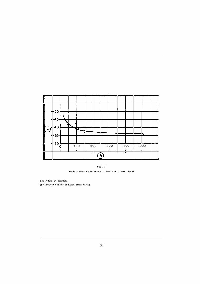
The shear strength as with most soils is rel ated to the stress l evel i.e., the higher the confining pressure, the smal ler the angle of shearing resistance. Fig. 3 .3 , borrowed from Loise l le and H urtubise (50), i l lustrates a change from 48 to 37° with an effective minor principal stress varying from 1 00 to 600 k Pa. For a confining pressure exceeding 600 kPa, the angle of shearing resistance remains nearly constant varying between 36 and 37°.
Water content during compaction has an effect on shear resistance. A smal l variation above or below optimum may result in a decrease i n angle of shearing resistance varying between three and 5° . Fig. 3 .4 taken from Lafleur et al. (47) shows that fact very clearly.
The coefficient of permeabi lity is a fonction oi the fines content and mostly of the clay-sized fraction. Data i n Tabl e 2 of Appendix A indicate that for a variationof the clay-sized fraction from 4-5 % to more than 1 5 %, the permeabi lity coefficientdrops from a range of 1 0 6 - 1 0-9 mis to the range 1 0 9 - 1 0- 1 1 mis, whichcorresponds to a very impervious material . Thi s phenomenon is shown by the Fig. 3.5 (47) in which we see the variation of the fonction Y = e ( 1 -a) [where « e »
is the i nitial void ratio and « a » the fraction of particles smaller than 0.074 mm] with respect to permeabi l ity.
These results confirm the study made by the Norwegian G eotechnical I nstitute (3 1 ) on the effect of compaction and fines content on permeabil ity.
The few deformability and consolidation parmeters avail able are also summarized i n Tabl e 2 of Appendix A. Most of the data are from C anada where large dams have been built recently and where analyses were made to simulate as much as possible the different phases of dam construction and operation . Triaxial
25

tests were conducted for a variety of conditions (pressure l evels, densities, water contents, stress paths, etc.) so that deformabi lity parmeters to be used in finite element analyses could be chosen ( LG-2, LG-4, Mica, Canada). The in situ plate-bearing tests performed on the fou ndation of Squaw Rapids Dam (Saskatchewan, C anada) gave more real istic deformation moduli than those measured by triacial compression tests.
Sorne specia l post-construction l aboratory testing programs have been carried out in order to explain excessive local deformation which occurred during the impounding or operation of the reservoir. Let us mention for example, the compressibility tests ran i n oedometric cells on Northern Quebec moraines ( LG-3 and LG-4 projects). These tests showed that the compressibi lity of these moraines is significantly i nfluenced by the moisture content and the degree of compaction i n the fil ! ( Fig. 3.6). As i l lustrated, the si lty a n d moraine compacted below 90 % o f maximum Standard Proctor a n d on the dry side (3 % below the optimum water content) can undergo up to 6.5 % (compression) sett lement during saturation under a 1 ,000 k Pa confining pressure. This settlement phenomenon similar to the behaviour of a loessial soi! decreases in i mportance with increasing compaction and becomes insignificant for 94 % or more ot the maximum Standard Proctor independently of the water content during p lacement (49).
In the case of the coarse Alpine moraine, the French approach to establishing the m aterial properties can be summarized as fol l ow (84). Sorne years ago, the tendancy was to test the coarse material in the l argest possible equipment to be as close as possible to the real gradation. The tendancy today is to use smaller equipment but to try to establ ish correlations between the measured parameters and the real gradation. To reach these resu lts, the strength parameters are obtained in tests where the conditions in situ are reproduced as much as possible by modeling the stress paths and the flow nets and not only the angle of shearing resistance. The strength parameters are measured for different grading curves to give a better understanding of their variation.
27

1 11 1 1 1 1 s} •. 1 1 200 40 10 4 '5" OO � 1 ; ' / �. ....... ......... � .
-
Jo V i ..... �· '-6 ..... /""' .
1 / � -- 1 � 1 1
1 y Il'. � .... � 1
1 4>.1l%: '.; � 1
6 ; V , � '/ , ...... ' � 1 ,...!/. :
r i,/ : lt/ : V : ' ®
1 v"' �� � ( Il 1 ' '
0 ... . � ' 4
1 V J� � ' lY 1
�" � 1 '
1 v"" l:i?" v"" 1 V ) V : ' V � ,..., i.:. '
Io -
' """""' i--- i.--""" V ' '--.... V ' -- 1
1 -.__. ......... ......... : ' ' 1
0 1001 1
0 1 1 1 0 1 0
Fig. 3 . l .
Grain size distribution curves ( E astern Quebec moraines).
(A) % passing.
(B) Diameter mm.
(C) US Std. sieve.
1 Manicouagan-3 Trench 22.
2 Manicouagan-3 Trench 22 a.
3 Manicouagan-3 Trench 22 b.
4 Outardes-4 Sample B-2- 1 .
5 Manicouagan-3 Borrow 1 3 .
6 Outardes-3 Area C.
7 Outardes-4 Sample B-8-3.
28

(A)
' ' �, S r = 1 0 0 % 1 �
� ' 1 2 2 1 o �-+--->--+----+--+--�--+----..---r------; 1-r
,
; 1 ...... ..-------.,_----,... �
/ V V 1 8901--���l--���1+-�,/'--+�-+�-+-�-+-�-+-�-+-�-+--
t�V
5 6 7 B 9 1 0 I l
® Fig. 3.2.
Moisture - density curves ( E astern Quebec Moraines).
Density ( kg/m3).
(B) Moisture content (%).
(C) Saturation curve 1 00 %.
l Manicouagan-3 Trench 22 .
2 Manicouagan-3 Trench 22 a.
3 Manicouagan-3 Trench 22 b.
4 Outardes-4 Sample B-2-l
Manicouagan-3 Barrow 1 3 .
6 Outardes-3 Area C.7 Outardes-4 Sample B-8-3.
29
1 1 1 1 ,
� 50 1
. ! - 4 5 \
� r"... • 0 40 """"r-:......___ .
35 .
- 30 0 400 800 1 200 1 600 2000
1 t 1
(s) 1
Fig. 3 .3
Angle of shearing resistance as a function of stress level.
(A) Angle 0 (degrees) .
(B) Effective minor principal stress (kPa).
30

flj,
44
42
40
38
36
34
•
10
•
-� . 1 • •
- �
20 30
Fig. 3 .4
• 0.97 <; Rw � 1 . 02• Rw > 1 . 02
Rw < 0 .97
( Ry-= 1 .0 )
( Ry=0.97 )
( Ry-=0.97)
40 d ( M Pa )
Angle of shearing resistance 0 ' as a functionof confining stress (cr'), compaction water content (ro) and density (y).
Optimum water content
(R,) Maximum density.
3 1

1 1 · '
' i ! 1 1 : 1 1
1 1 1 1 1 1 1 1 1
1 1 1 : 1
25
1 1 1 1 1
! 1
2 3
2 1 -1 1 i 1 Il 1 1 v
1 Il
JV �V 1 ' / •
0 1 9
p Il li )V . 1 7
/. " Il 1 51.l'
' /
0 j 1 1 1
1 L1 1 i
J./�� .V '� e
/ • � V V '"
V y Il
� 'r I
; i Y" V� li /
y i , . / 1
V
Fig. 3 .5
// � i. /
V
1 '{Y: i j ' Il /',/
�V V
1
1
1 1 . ' '
1
1 1
Effect of void ratio (e) on permeabi l i ty coefficient.
(A) Coefficient of permeability (cm/s) (B) Y : e ( 1 -a)
e : void ratio of the soiL
' 1 � i 1 : i ! 1 ·
: ' 1 1 1 1
a : fraction of particles smaller than 0.074 mm.
32

7
6
5
4
3
2
� î 1 1-----l- + - ,_ ..... � �·-�� h -'� '
� �+- - t t
� 1_ v )...-1 - i.- l
r v t
� 17+-,.,.. 1
� t �· t T
r--1, k j ' 1 r-., 1
· -... 1 "� � +,--, 5
I', .... '1' . : î l ; 1 �!"
0
_L_ l ---i-,� -+ "'
l'\J 1 -��
>*= I" [',.! '-� 1 ,_ +
-+- ....,... '
·-� � ! 1 t · - -
! 1 t
1 + -
'cJ.._
+- -- � - t
i � ._,_ - c--t--' -t
f'-. -.......... !'-..
'\. "'!'\ ' 1\ t
� - ;
, ... 1'
+ :
� '\
!
I' "
' -
f'\
j j c
! + -+
.. '
t t 1 1
._t--H-..;.._•3 t +- �� L .
1 1 1 '"' 1 [\ ' ! t
"N_ . •f\ 1 1 ��
1 t j l j !'.:
'\ t + � J\
t ' �b t ·J, i - ' 1 �
2 3 4 5 6
Fig. 3 .6
l - � -�
-t
�
i
K2 1 -\
1 \
1\ ' L_j
r'\ 1 \ N
l\ 7 e
--
1 _,_
' + f
,..
r\r \
Compressib i l ity of the moraine vs compaction and water content.
(A) Compressibi l i ty (%).
(B) Water content (%).
( 1 ) 82 % Std. Proctor.
(2) 86 % Std. Proctor.
(3) 90 % Std. Proctor.
(4) 94 % Std. Proctor.
(5) 98 % Std. Proctor.
33
t- +-
�
- c-��
c--t--
ËE �
1
-++ ;J_,_
-- t- � t--+-----+-----
9 10

4. DESIGN AND SPECIFICATIONREQUIREMENTS
As a water retammg structure, a dam must exhibit a reasonable degree of imperviousness combined at the same time with a strong mechanical resistance to withstand various external forces. In the case of the morainic m aterial , these characteristics can be obtained by a well-graded grain-size distribution and an adequate density.
Whi le the need for a detailed specification and an extensive control of the grain-size distribution is generall y accepted, Jess consensus can be found throughout the world on density specifications of requirements.
Currently, there are three different approaches to the construction of a dam with moraine as the impervious zone and these of course affect the design and the placing requirements. They can be described as fol lows :
a) The moraine is spread moist i n rel atively thin l ayers ( 1 00 to 450 mm) andcompacted with compactors to its maximum dry density at approxim ately the optimum water content or thereabouts.
b) The moraine is placed wet and spread at a water content substantia l ly higherthan its optimum in l ift heights varying from 200 mm to 2.0 m and compacted general ly by the hauling and spreading equipment and only occasionall y with l ight compactors.
c) The moraine is p laced in tempory pools of water formed on the raisingembankment. Densification is obtained by consolidation under the weight of the moraine.
The first approach is used mainly i n Canada, USA and Eastern Europe, while the second was developed and is particularly used in Scandinavia (Sweden, N orway, Finland). The third approach was in itiated and is largely used in the USSR.
Placing the moraine i n wet or even i n saturated conditions has the fol lowing advantages :
- greater embankment deformability during construction and i mpounding of the reservoir, thus reducing the possibil ity of cracking the i mpervious zon e ;
- greater embankment deformabi l ity which reduces the arching phenomenon and th us the danger of hydraulic fracturing ;
- by dumping moraine i n water, work can go on continuously i n severe climatic conditions throughout the calendar year, and placing it in relatively thick l ifts redu ces the need to el iminate the coarse partiel es ;
3 5

- dumping moraine i n water has the additional advantage of avoiding l ayering in the embankment and favours the fi l l ing of voids with finer material .
The segregation phenomenon is quite important and deserves some discussion.
The experience of the USSR in the Kola peninsula, where non-uniform moraines were used extensively for dam construction, showed that the degree of segregation depends on many factors : grain-size distribution, initial water content, water pool depth, height of the dumped layer, type of transportation and method of delivering soi l s to the embankment (87).
The larger the coarse fraction in the moraine, the greater the degree of segregation. With an increase i n the fines content and i n the water content, segregation decreases. The segregation phenomenon is more dangerous when the boulder content reaches 25 % and more and the content of fines is Jess than 30 (Vo .
Segregation occurs either when " dry " soil is being placed or when it is being dumped it in water. With the " dry " method of placing moraine, the l arger partiel es separating from the remaining mass rol l down the slope and reach the bottom . When the soil is dumped into water, the opposite results : on the upper part of the underwater slope, the soil converted into quick material retains the l arge particles and the finer particles slide down and accumulate at the bottom forming a gentle si ope.
The separation of the moraine into various fractions increases with an increase in the thickness of the dumped l ayer.
When low-fine moraine is being placed, segregation occurs at a smaller thickness of the l ayer since for a dumped layer of 1 to 1 .5 m and a pool depth of 0.5 to 0.7 m, the process of segregation, which begins i n the upper part of the s lope, can reach the base. The water is not deep enough to stop the boulders from roll ing down the si ope. The danger is that the coarse partiel es deposited at the base of the slope form transversal drains across the core of the dam. Segregation decreases if moraine is dumped on the edge rather than on the slope and pushed to the ponds by bul ldozers.
4.1 . IN THE EMBANKMENT
4.1 . 1 . Grain-size distribution
Two schools of thought exist in the selection of design criteria for the impervious moraine portion of embankment dams.
I n North America, and to a lesser degree in some European countries, the fines content is emphasized* . A minimum of 1 5 % is required for a permeability I ower than 1 o-6 mis to be obtained. I t is desirable to have a maximum of 50 % of the fines
• ln America and some European countries, si lt-sized particles are smaller than 0.074 mm andclay-sized particles smaller than 0.002 mm. ln USSR and other European countries, s i lt particles are smaller than 0.050 mm and clay particles smal ler than 0.005 mm.
37

content to avoi d difficulties i n p lacing and compaction and to avoid the generation of excessive pore pressures during construction. M oreover, for s i lty to sandy moraines, the maximum particle size varies between 1 50 and 300 mm and must not exceed 213 of the lift thickness. For c layey moraines where the l ift thickness has to be Jess to al low for better pore-pressure dissipation and compaction homogeneity, the maximum particle size varies between 75 and 200 mm.
In Sweden and N orway, where m any dams are built during the wet summer season, the wet compaction method is often preferred, since the water acts as a lubricant helping the penetration of large particles into the finer m atrix . The tendency is also to use thick l ayers where fairl y l arge b lacks up to 500 to 600 m m i n diameter can b e buried. I n every case however, the boul ders are not l arger than 213 of the l ift thickness. The fines content can be as low as 1 5 % of the 5-mm fraction which could lower the fines content of the total sample to less than 1 0 %.
Near the abutments, close to the rock foundation and i n special zones, a more plastic moraine i s general ly required. I f such a m aterial is not avail able, the same moraine can be used with selective borrowing i n the borrow area where the fines content as well as the natural water content are higher. The moraine can then be compacted on the wet side of the optimum ( + 2 %) to compensate for the Jack of plasticity of the natural m aterial . The condition obtained may not be permanent. The addition of a few percent of bentonite to the moraine is more expensive and may give improved performance. However the soi! chemistry of the situation should be careful ly studied to ensure that the possibil i ty of an adverse reaction i s acceptably remote during the l ife of the dam.
On l arge projets, trial compaction embankment tests are often carried out at the site to better define the optimum l ift thickness, the size of the l argest particle, the best type of compaction equipment and the number of passes to be made.
4.1.2. Water Content and Density
When moraine is spread and compacted in thin l ayers around its optimum water content, the water requirement ranges between + 2 % and - 1 to - 2 % of the optimum. The depth of the ruts m ade by the equipment rol li ng on the fil l wi l l sometimes indicate that the water content is getting too high. A 1 50-mm rut is often considered as such a l i mit. Compaction of silty moraine is more sensitive to water-content variation, especial ly when water content exceeds the optimum.
I n the case of the wet-compaction method, the p lacing water content i s normal ly above optimum and is only l imited by the sinking of the equipment on the fil ! . The water content may be in the order of 4 to 6 % above the optimum. A 200-m m tractor rut is about the l imit for compaction to be accepted.
39

When moraine is p laced in pools, the water content of the moraine at the time of placing has no great influence on the final density, but a higher natural water content wi l l reduce segregation during placing operations.
In the case of the first approach with rel atively thin layers, the compaction requirements are about the same everywhere : a minimum in situ density specified as a percentage of the maximum Standard Proctor density. A minimum of 97 to 98 % Standard Proctor is general ly required, except in Scandinavia where 95 % of the Modi.fied Proctor is used. To reach this goal, the design normally specifies the l i ft thickness, the range of water content for compaction, the type of compaction equipment and sometimes the number of passes. In one case (9 1 ), 1 00 °1i1 StandardProctor was specified so as to obtain a very rigid material to I imit the differential settlement between the core and the adjacent stiffer filter zones.
The size fraction of the material which is used in the standard test and what allowances, if any, are made in relating this to the total material in the dam are general ly not stated in the information gathered for this report. l n America, the ASTM specific method (A or D) for determination of the Standard Proctor maximum density is used depending on the percentage of the corresponding coarse fraction. White method A test is easier and faster to perform, method D tests are considered better suited for typical coarse moraines.
Comparative tests performed according to methods A and D with a large rigid box (0.6 1 m x 0.6 1 m x 0.36 m - ASTM D-2922) demonstrated that both method D and method A (when duly corrected for the coarse fraction according to U S B R E-38 relationship) can b e used for the moraine with a n oversize fraction not exceeding 30 (�i of the total weight. Both methods yield results considered to beconsistent with the l arge test box and the in situ conditions. The total field density is often determined with a nucleodensimeter, calibrated against known density concrete blacks. The replacement method using a large sand cone gives results of the measured field density some 50 kg/m3 higher ( i .e . , 2 to 3 % deviation).
In Scandinavia and in the USSR in particu lar, the density of the material is not so impotant as long as the angle of shearing resistance i s greater than 30° and the permeabi l ity less than 1 0 6 m/s (52).
4. 1 .3. Width of the Core and Filter Requirements
The use of morai ne as the impervious element of a dam, in spite of its high performance, requires some supplementary l ines of defense. The width of the core and adequate fi lter zones represent, among others, the most important factors for an efficient and safe behaviour of the core.
ln current practice when vertical moraine cores are used, a minimum core width is considered to be 0.3 times the hydraulic head. For incli ned cores, smaller widths are accepted mainly when the moraine is homogenous, contains a higher percentage of fines and exhibits some plasticity.
4 1

The selection of the filter material and the width of the filter-transition zones are major questions. The fi lter zone constitutes the first and foremost I ine of defense against i nternai erosion of the i mpervious element of the dam.
The filter design criteria, aimed at preventing any soi l particle m igration from the core to the adjacent zone of the embankment, while al lowing free drainage of water through the core are traditionnally those suggested by Terzaghi ; i .e . : the D 15* of the fi lter should be Jess than four to five times the 085 of the base soil, andD 1 5 of the filter should be Jess than at l east five times higher than the 01 5 of the base soi l .
Whi le the choice of these criteria generally seems to ensure a satisfactory behaviour of the dam, some incidents recorded at structures using coarse broadly graded materials have raised some doubts about their adequacy in protecting the core. Considering that these criteria were developed for materials with a uniform gradation, their use with coarse broadly graded materials (coarse moraine) could lead to the selection of very coarse filters (82).
Consequently C asagrande ( 1 5) recommands to use " next to coarse til l , or similar core materials , a zone of good quality concrete sand ; and next to that zone one or more coarser l ayers when using downstream a rockfi l l zone ".
The US Soil Conservation Service (SCS), based on recent studies on filters and their experience with broadly graded soils, changed their design criteria for filters in embankment dams. Thus for sands, s i lts, clays and s ilty and clayey sands (40 to 80 % finer than 0.075 mm), they use 015 of the fi lter < 0.7-mm (83).
Sherard et al. (82) recommend that " for impervious soils containing gravels, the grave) s ize should be ignored and the ses criteria should be applied to theportion of the soi! gradation curve which is finer than the No. 4 sieve (5 mm).
Kleiner (39) recommends the use of the fol lowing supplementary criteria for filters next to coarse, broadly graded materials : a) the upstream filter should contain a generous percentage of medium to fine sans so that, i f core cracking occurs, a supply of sand is avai lable to wash i nto and thereby plug the crack ; b) the maximum percentage of non-plastic fines (finer than 0 .080 mm i n the fi lters) i s limited to 5 % (generally Jess than 2-3 %) to ensure adequate permeabi l i ty. c) themaximum particle sizes of the filters are l imited to 75 mm to minimize segregation.
The possibil ity of internai i nstabi l i ty of the fi lter m aterial , where fines can be washed out by seepage, should also be considered. This phenomenon would \eave the moraine core unprotected (32).
4.1.4. Geometry of embankment
The moraine material exhibiting in general h igh strength characteristics, has a very s light i nfluence on the outside geometry (slopes, crest width, etc.) of the embankment. Foundation conditions, seismicity and eventually the characteristics
• D,, = particle size of filter for which 15 % by weight of particles are smaller.
43

of the shell material are the main parameters conditioning the embankment geometry. A review of the current practice in dam design i ncorporating moraine material can be summarized as fol lows.
4. 1 . 4. 1 . Homogeneous embankment
In Canadian (Eastern) practice homogeneous moraine embankments constituted of compacted moraine material sited on rock or firm soi! foundation are provided in general with upstream slopes of 2.25 - 2.5 H : 1 V (H horizontal ; V vertical) and downstream slopes of 2 H : 1 V. Crest widths of 7.5 to 9.0 m are genera l ly adopted (80,64).
The USSR practice, where the moraine i s compacted only by the hauling and spreading equipment or where the material is dumped in water pools, upstream and downstream slopes of 3 - 4 H : 1 V and 2.25 H : 1 V respectively are adopted ( 1 2) . The crests of these dams have a width of 9- 1 2 m (85). However dams i ncorporating conventional compacted moraine material are provided with steeper s lopes (2 .25 -3 H : 1 V upstream slopes) and narrower crests (4-6 m wide).
4. 1 . 4. 2. Zoned embankment
Dams sited on rock or firm soi! foundation, are provided with the fol lowing outside slopes (Canadian practice) (64).
T ype of dam
Rockfill . . . . . ....... .. . .
Earthfill . . . ....... . . . . . . . . . .
Ups tream
1 .7 -1 .9 H : 1 V 2.25 -3 .0 H : 1 V
SI opes
Downs tream
1 .6 -1 .8 H : 1 V 2.0 -2.25 H : 1 V
Crest width of 8- 1 0 m are designed to accom modate the heavy hauling and compacting equipment used in modern dam construction. For smaller dams, crest width is reduced to 6,6 m .
Simi lar geometrical parameters are used for the design of zoned dams built with moraine core dumped in water pools. The dam outer slopes are constituted of a number of steps with steep slopes ( 1 .25- 1 .8 h : 1 V) separated by horizontal berms of various widths. Crest widths of about 1 0 m are also currently adopted ( 1 2) .
While the moraine core outside l imits are relatively gentle for the material dumped in water ( 1 ,0- 1 , 1 h : 1 V), cores of compacted moraine are provided with contact s lopes as steep as 0. 1 5 H : 1 V. At dams with inclined cores the core contact slopes are general ly in agreement with the outerslopes of the embankment.
4.2. IN THE FOUNDATION
An acceptable moraine foundation for embankment dams is defined in general
45

as a firm undisturbed material having a density and an imperviousness equal to or greater than that of the overlaying compacted impervious zone of the dam.
Thus, loose and pervious materials are removed from under the core and filter areas. M oraine under the shel l area, free from organic of other undesirable soft materials, is acceptable without specific density requirement if the original moraine deposit was not disturbed. However the cleared surface is always recompacted after the excavation operation, and cleaning and grubbing operations and stripping and removal of peaty m aterials are a lways required everywhere under the embankment.
I t should be mentioned that the moraine in situ exhibits i n general a very high density, due to its consolidation u nder the weight of the glacier. Consequently the presence of loose and pervious m aterial is l imited to the upper part of the formation. Whil e only l imited data exist on the l iquefaction potential of the moraine i t can be assumed that under some severe earthquakes the material can l iquefy. Laboratory tests carried out on moraine (Canada) have indi cated the significant influence of the density on its dynamic strength. As an example it can be mentioned that an i ncrease of the density from 1 600 kg/m3 to 1 800 kg/m3 of a C anadian (Quebec) moraine indicate an increase of 1 OO % of its cyclic strength. In general, however the moraine does not represent a significant l iquefaction potential at low to moderate earthquake shaking.
For a tight contact between the core zone and the so called impervious moraine foundation, a eut-off trench is general ly required. The core trench is normal ly excavated in accordance with the fol lowing requirements :
minimum depth 1 / 1 0 H ( H : hydraulic head) ;
- minimum width 3 .0 m or 30 % to 50 % H (with a maximum of 1 0 m) ;
- excavation side slopes : 2 horizontal to 1 vertical .
For a stratified foundation with pervious lenses o r l ayers, the core trench i s made deeper and m ay be provided with a core drain, a pervious downstream blanket and toe drains of variable depth depending on foundation characteristics, water table, etc. Downstream toe berms or upstream impervious blankets below the shell may also be required depending on the local conditions.
47

5 . CONSTRUCTIO N
5.1 . PLACING THE MORAINE
5. 1 . 1 . Compaction in layers
The use of heavy compactors ( 1 0-50 tons) becomes efficient only if the water content of the material is at or around its optimum. I n general, a scatter betweenWopt + 2 % and Wopt - 1 % is considered acceptable . Greater densities areobtained when the layer to be compacted is Jess than 300 mm thick. However, with the energy of compaction developed by the equipment avai lable today, it seems possible to compact satisfactoril y l ifts of material as thick as 1 m if the material is not too clayey (35) .
The number of passes required to obtain the specified degree of compaction depends on the size and type of compactor. Two main types of compactors are used to compact non-plastic moraine, pneumatic and vibrating compactors. The heavy 50-ton pneumatic rol ler, although cumbersome on the rolled surface, has been commonly used in North America to compact non-plastic types of moraine. On the La Grande Project (Quebec, Canada), the prescribed four passes of 50-ton rubber-tire rol lers were general ly sufficient to obtain a target density corresponding to 97 % of maximum Standard Proctor density, as long as the moraine water contentwas kept within - 1 % and + 2 % of optimum. The l ayer thickness in this case was450 mm.
Vibrating rol l ers, general ly l ighter (6- 1 0 tons), are used main ly on si lty moraine. The reasons for this preference seems to be that a smaller type of compactor moves more easily on a restricted core surface and a higher degree of energy can be transmitted to the l ayer by a vibrating rol ler than by a static one. A 50-ton pneumatic roller cannot adequately compact a 1 -m thick layer of moraine with a reasonable number of passes, whereas the heavy vibrating rol lers can do it satisfactori ly (84).
The users of both types of compactors seem satisfied with the behaviour of the compacted moraine during and after construction. The uniformity of compaction may be questioned for both types of compactors.
The pneumatic rol ler performs better on an uneven surface and is Jess sensitive to the presence of boulders and cobbles close to the surface of the layer than a vibrating rol ler, but the latter compensates by having a better punching action which tends to level the surface by the dis placement of cobbles within the compacted layer. Both types of compactors wi l l sink in the moraine if the material is placed on the wet side (water content more than 2 % above the optimum).
49

At M anie 3 (Quebec, Canada), fine moraine p laced on the wet side (Wopt + 2 %) in thin l ayers ( 1 00- 1 50 mm) was satisfactorily compacted with l ight vibrating rol lers (Jess than six tons). The effectiveness is i l lustrated by a comparison of the performance obtained with rubber-tire rol ler compactors. Whi le the average density obtained with rubber-tire rol l ers reached 97.5 % of standard Proctor density (2.5 standard deviation) with 38.2 % Jess than 97 %, the average in situ density of the material compacted with the vibrating rollers gave a value of 97.7 % of Standard Proctor density ( 1 .9 standard deviation) with only 25 .8 % less than 97 % as shown on Fig. 5 . 1 ( 1 9).
To compact the clayey type of moraine encountered i n the Western Provinces of C anada, sheepsfoot or padfoot rol lers are also used as well as 50-ton pneumatic rol lers. To be efficient, the kneading action of the compactor should not be i mpeded by cobbles or an excessively l arge amount of grave! i n the soi! . It is common to l imit rock size to the spacing of the sheepsfoot, typically 1 50 m m .
P lacing can be better control led when t h e natural water content of t h e borrow material is close to the optimum, preferabl y somewhat below. I f the natural water content exceeds 2 % of the optimum, particularly in silty moraines, the material has to be dried mechanically or artificially in order to be properly p laced.
When the ambient air is dry enough, the material can be dried by mechanical aeration either in the borrow pit or on the fil l (4 1 ). However the most effective way to reduce the moisture content is to use a rotary kiln dryer. This method was successful ly used on l arge dam sites at La Grande and at Manie 3 in Canada : a 1 .5-2 % reduction was generall y obtained. The warm material could also be p lacedduring l ight rain or early freezing periods (ambient temperature Jess than - 3 oqwhich extended the placement season by about one month .
A comparison of the influence of water content on moraine compaction il lustrates the results obtained with the same material placed at natural water content (W = Wopt + 2-3 %) and after being dried in a ki ln (W = Wopt + 1 .5 %). The average density obtained at natural water content reached 97.7 % of Standard Proctor with 25 .8 % ot the results smal ler than 97 % while after the material was ki ln dried, the average density was raised to 98.8 % of Standard Proctor, with only 13 % of the results under 97 % ( Fig. 5 . 1 ).
The coarse well graded Alpine moraine can be satisfactori ly compacted in l ifts of 50 cm by 4-6 passes of 8-20 ton vibrating rol lers (smooth). Scarifying the previously compacted layer to a depth of 5-7 cm and eventual ly wetting of the scarified surface is in general required to obtain an adequate bond between the compacted layers (84).
The main problem encountered with this type of material is segregation. Particular measures are taken at the borrow area, during material transport and spreading before compaction, to avoi d this segregation (84).
5 1

5.1 .2. Wet compaction
Placing of moraine in relatively high moisture conditions (rainy weather, high natural water content) is done by the wet compaction procedure as developed in Scandinavian countries.
One method is to spread the moraine having a water content of 2 to 6 % above its optimum in layers approxi matel y 250 mm thick and to compact it with heavy bulldozers weighing at least 1 5 tons. No lower l imit for the density of the material is specified after compaction.
A second method is to spread the moraine in rather thick l ifts (0.5 to 2 m) and compact it with vibrating rol lers weighing 6- 1 0 tons. No lower l imit for the density is specified after compaction.
Thick layers favour high productivity since a l arge number of cobbles and boulders can be included in the fi l l . This reduced the necessity of scalping them at the borrow area. Furthermore, the surface of the fil l is less frequently exposed to rain and saturation, which is a major concern in rainy areas.
Placing the impervious material in wet conditions could cause high pore pressures in the fil l . In spite of a relatively low permeability, these pore pressures do, however dissipate relatively rapidly. This can be explained by the relatively high consolidation coefficient of moraine. The high initial pore pressure, which is a consequence of the wet method, therefore does not general ly require special procedures for dam stabi lity to be ensured. The method has the disadvantages however of preventi ng the free passage of the hauling equipment across the core.
The placing of moraine in thick layers produces a Jess uniform material . The dry densities vary with the depth and the water content. As shown in Fig. 5 .2, the degree of compaction tends to be lower at the bottom of the layer than at the top, and decreases with a higher water content (35).
According to curves, maximum compaction occurs at a depth of 0.2-0.3 m. The reduced compaction in the upper part of the layer can be explained by cracking produced by vibrating rol lers, to a depth of about 5 cm and perpendicular to the direction of travel .
The presence of coarse particles in the layer i ncreases the segregation possibilities. However, the vibration compaction combined with a high moisture content does reduce the probabil ity that unacceptable segregation will persist in the compacted fi l l .
Full-scale tests both o n t h e compaction of t h e material a s wel l a s t h e placing operation have to be carried out.
5.1 .3. Moraine dumped in water pools
I n the USSR, the impervious zones of many dams are made by dumping moraine into water. Two continuous longitudinal dikes about 3 m in height are built along the upstream and downstream l imits of the core while transversal dikes are built across the core 1 OO to 200 m a part, th us forming a series of independent basins
53

to be fi l led successively. Each basin is fil led with water to a depth of 2 to 2 .5 m. Drainage pipes are i nstal led at the desired level to l et the water go into adjacent sections when the pool is fi lled with moraine. The moraine is unloaded at the water's edge of the working section and is bul ldozed into the water. The required soil compaction is provided by repeated passes of the tractors. Trucks haul the moraine rol l ing over the previously fi l led section and thus i mprove compaction. Sometimes, especial ly in the sections close to the abutments, which are fi l led l ast, the dumped material must be further compacted.
The optimal thickness of the l ayers, the water depth in the pool and the rate of fi l l ing are determined by large-scale tests performed during the initial construction period.
I n general, the surrounding dikes are made with l ayers 0 .5 to 0 .7 m thick, compacted by the hauling equipment while the water depth in the pool can reach 1 .5 to 3 m (95).
Even the shape of the bottom of the <lump trucks has an effect on soi! segregation during u nloading. For i nstance, with a fiat bottom, the rate of s l iding and segregation increases, whereas for an irregular bottom, both the rate of sliding and segregation decrease.
5.2. WINTER CONSTRUCTION
Two approaches are considered for construction under severe cl imatic conditions :
a) just before the ground freezes, the placing of morainic material is stopped and the soi! already in place is protected with an insulating blanket to avoid frost penetration ;
b) placing operations continue even during severe freezing periods but special techniques are used : chemicals are added, the moraine is stockpiled or heated or dumped in water, etc.
The rate at which the unfrozen moraine loses heat and freezes during construction depends on many factors, such as the temperature of the fi l l in the borrow pit, the distance hauled, the construction surface area, the placing rate, the ambient temperature, the wind velocity, etc.
In North America and Scandinavia placing is prohibited during freezing periods so as to avoid the presence of ice, snow or frozen materials in the core of the dam. The melting of these frozen materials at a I ater date coul d soften the compacted moraine, reduce its shear strength and increase its permeabi l ity.
lt should also be mentionned that under severe winter conditions heavy snowfal ls and strong winds - the placing of morainic materials becomes more expensive and can j ustify avoiding construction under those conditions.
l t is also recom mended in North America and Scandinavia that freezing of the in situ compacted material be avoided. The formation of ice I enses during freezing,
55

which is accompanied by heaving and fol lowed by thawing, produces a Joss of density and a softening of the m aterial .
In the spring, any frozen material must be removed or thawed before embankment construction is resumed. Material with excessive moisture content, which cannot be satisfactori ly dried on the fil l prior to compaction, must be removed. Density tests are used to ascertain thawed embankment layers are adequate.
Thus, at the onset of winter, the normally p laced moraine material should be covered with an insulating blanket to provide protection over the winter months and reduce the amount of excavation of frostloosened material (94).
The relative efficiency of some insulating blankets was tested at some projects in Canada (24). With a freezing index of 2 000 °C-days, the frost penetration in a moraine not protected against frost can reach 3 to 3 . 5 m in one year. A protective cover of 0.6 m of snow can reduce that penetration by 1 .8 to 2 . 1 m leaving 1 .2 to 1 .4 m of frozen moraine. A 1 . 5 to 1 . 8 m thick granular blanket can reduce the penetration by 2.8 to 3.3 m leaving 0.2 m of frozen moraine. A combination of 0.45 m of sand and grave! and 0.75 to 1 m of snow offers enough protection to avoid any frost penetration i n the moraine.
I n the U S S R, for many years, soi! i n dam construction has been placed during the winter at air temperatures as low as - 40 °C (95). The excavation and stockpi l l ing of moraine du ring the summer and its subsequent use during the winter were and are sti l l used in USSR to allow for winter construction. During stockpil ing, the material is mixed with a low water content material like sand and grave! and some chemicals l ike commercial sodium chloride. Stockpiles 50-60 m wide and 1 5 m high with a volume of some 200 000 m3 are currently used. Sometimes, during excavation, the top of the pile is heated. The soi! at a temperature of 6-8 °C is hauled from the stockpile to the site in trucks also heated by exhaust gases. At temperatures below - 1 0 °C and especial ly in windy weather, the soi! is covered by tarpaulins to reduce heat losses during transportation. The soi! delivered on the site is immediately spread i nto l ayers 0.4 to 0 .5 m thick. The time for dumping and spreading does not exceed 1 0 to 20 min. After being spread with the bul ldozer, the surface of the freshly levely soi! is sprayed with a concentrated solution of ch lorides.
The upper part of the layer treated with chlorides remains plastic when it freezes during compaction and does not hinder compaction of the underlying material . Frost does not cause the soi ! salted with chlorides to heave ; the surface i s free of cracks and ice between l ayers is absent. The contacts between the layers being placed are monolithic. I nvestigations established that the extremely salted and therefore saturated surface of the soi! is a natural accumulator of cold and leads to a more intense cooling of the lower part of the l ayer.
In regions with a wet climate, the moisture content of the moraine in the pi le may be higher than the optimum even i n summer. This rules out placing moraine in winter by the process i ndicated above. Because of the increased moisture content, the soi! has a weak load-bearing capacity. Trucks move with difficulty over the soi!
57

being placed ; it is springy, and deep ruts form on the surface which hamper compaction of the soil when they freeze. Therefore, it is impossible to treat the freshly-leveled soi! surface by spraying with chloride solutions. The surface of the moraine material not treated with the sait solution becomes covered with frost cracks when it freezes, is fractured by the vehicles, and has the appearance of dumped rubble without cohesion and solidity.
It should be pointed out that when the moisture content is high, the solution penetrates Jess than in soi! with a lower moisture content. For salting to be effective, new techniques are needed to force salting of the soil to the required depth.
Dumping the moraine into water is a method developed more recently and is now used quite extensively. The basic principles are the fol lowing : a) the soi! remains constantly underwater, and is thus protected against freezing ; b) the water pool is a powerful heat conductor and the water can be heated if necessary ; c) the surface of the water in the pool can be protected with various insulation boards to reduce heat losses.
5.3. CONTACT ZONES AND INSTRUMENTATION ISLANDS
Screened moraine is p laced in thin l ayers against rock foundations, abutments and concrete structures within the core zone. The fil l p laced around instruments located in a protective is land is genera l ly placed in l ayers half the thickness of surrounding layers. Smaller compactors (vibrating plates or rollers) are used to compact these restricted fil l zones. I t is possible to satisfactorily p lace selected moraine in these zones, but special care must always be taken to ensure the sucess of such placing operations. At two locations in the La Grande Complex (QA-8 and T A- 1 0, Quebec, C anada), the fil l for such instrument is lands was p laced in a looser state than the surrounding moraine. The differential settlement at the time of impounding resulted i n sinkholes at crest level within the protection is land zone along instrument casings, or adjacent to the island zone. As cores are wide and instruments are located in the middle of the core zone, no stabil ity problem developed from those isolated incidents except l ocal abrupt and l arge differential settlements.
5.4. QUALITY CONTROL
The purpose of quality contrai is to ensure that the material characteristics and the construction procedures concur with the designers technica l specifications and that the final product meets the design criteria.
Depending on the moraine's characteristics and the construction method adopted, quality contrai is directed mainly at checking in situ densities or permeabil ities of the core.
The quality contrai programs of those who support the school of thought that emphasizes strength behaviour aim to ensure the moraine presents at least the
59
minimum required density which will guarantee the requested strength parameters and at the same time l imit deformation.
The quality contrai pragrams of the second school of thought aim to en sure that the in situ material has the minimum imperviousness specified.
These parameters are contralled by direct measurement and by the checking and monitoring of some other material characteristics or of the construction procedures.
Grain-size distribution and water-content tests are commonly used by both schools of thought, to take into account the influence of these characteristics on the strength and seepage parameters of the moraine. These tests are made fol lowing current standards and are carried out at frequencies varying from 1 per 1 000 to 1 per 5 000 m3•
ln situ density measurement or the degree of compaction is carried out in different ways as follows :
- Direct measurement of the in situ density and water content and comparison with the Standard or Modified Practor maximum densities and optimum water contents as measured in the laboratory.
Depending on design specifications, field values over 95-97 °Ai of the referencedensities (Std or Mod. Practor) are considered satisfactory. The frequency commonly used for these tests varies between 1 per 1 000 m3 and 1 per 5 000 m1.
- Direct measurement of the l ift thickness and strict monitoring of the number of passes of the compactor. Yisual inspection of the compacted material , which includes excavation of trenches and pits to check homogeneity and to assess the presence of local weaknesses especially at interfaces between l ayers of compacted moraine, completes the evaluation. M aterial density is then measured in situ only for record and with a frequency of 1 per 5 000 to 1 per 8 000 m1 . The holes excavated for inspection are later very careful ly fi lied and compacted in layers to avoid creating weaknesses.
Reference tests l ike Practor density and Optimum Water Content are carried out periodically (average 1 per 3 000 m1) or when the borraw material changes visibly. The modern tendency is to use the Standard Practor instead of the Modified Proctor.
For the coarse Alpine moraine of Mont-Cenis and Grand-Maison ( France), the placement specifications were l imited to a contrai of the grain size distribution (which contrais the permeabi l i ty of the material) and on the water content (which influences trafficabil i ty on the compacted layer, segregation, pore pressure development, etc.). No requirements for minimum compacted densities were specified.
For wet compaction and for dumping the moraine in water, the adequacy of the in situ material is checked only by permeability testing and by close monitoring of construction pore pressures. No in situ density measurements are carried out. If densities are measured during the wet compaction pracess, an average density measured at mid thickness of the l ift is more representative for quality contrai .
6 1

Sorne organizations use l aboratory or in situ permeability tests as monitoring tools with a frequency of 1 per 5 000 to 1 per 1 0 000 m3• However, these in situ test results are not considered to be a basis for rejection of the achieved compaction as can be the case when the density requirements are not met.
Finally, it should be emphasized that visual inspection of the compacted surface and of trenches and pits is considered as the most reliable means of quality control (homogeneity, layering, appearance of the compacted surface, etc.).
63

30
/ ® /! , � o 25 x 0 (,/o<97°/o i - 1 0
1 57 97 5 2 .5 0 24 3 8 2 62 97 7 1 9 2 5 8 -20
?O 3 1237 98 8 2 1 -0 0 6 1 3 0 30
0 I "_,-- 4 (_,
5 0
- 60 1 0
{CJ
- R O
-90
0 -.J__,::::;:.. .... ���".:-,- -���������---T""""',....=..,..��������������- 100 9 0 95 05 l l C
Fig. 5 . 1
Compaction degree obtained with rubber t ire rollers and vi brat i ng rollers on bulk and kiln d ried moraine.
(A) % of results.
(B ) % of results above.
(C) Compaction degree (%).
( D) Cumulative frequency.
( E) Distribution of results.
( ! ) Rubber-tire rol ler(bulk material).
(2) Vibratory rollers (bulk material).
(3) Vibratory rollers (k i ln dried material) .
(N) Number of samples.
(X) Average compaction <legree.
(a) Standard <leviation.
64
1 1 5
0

0 1 0
2 0
3 0
4 0
0 5 0
6 0
7 0
8 0
9 01 0 0
(A) Depth ( m ).
95 9 6 9 7 9 8 9 9 1 0 0 1 0 1 10 2 1 03 1 0 4' 1 05
® Fig. 5 .2
Dry density of moraine at water content of 8, 9 and I O % in relation to depth below surface.
(B) Dry density in % Std. Proctor.
65

#�� � �;<;;;;;;g:;s IS .... . :.� : . o. :_._ .. : . · _o . ·:· . ""' ·. · .� - - : . ... . .. . � . ... . ·
. � . ..d_-.:. � ·'..-. �>:.·_- _: _� ·- ·. ·
1 Moraine.
2 Sand and grave!.
3 Cobbles.
4 Water pool.
5 Polystyrene sheet.
6 Rockfil l .
7 Concrete.
8 Clay.
9 Grout.
Fig. 5 .3
Placing of moraine by dumping in water.
66
s_ 1 ...

6. EMBANKMENT AND FOUNDATION BEHAVIOUR
6.1 . EMBANKMENT BEHA VI OUR
The use of various methods for placing the core infl uences the behaviour of the moraine and thus the behaviour of the entire embankment. However, as shown below, the differences in behaviour are relatively small, and mainly related to the material characteristics. The fol lowing parameters generally characterize the performance of moraine material in the embankment.
6.1 . 1 . Pore pressures and seepage
The placing of moraine is normal ly accompanied by a pore pressure build up which can persist for a more or less extended period. Placing i t at or above the optimum water content and compaction with relatively heavy equipment can i ndu ce a pore pressure ratio up to Ru * = 1 . A Ru value of 0.5 can be tolerated under man y circumstances ; however a lower value of 0.3 is preferred. Sandy to silty moraines normally lose most of the placing pore pressures within a few months after construction or between construction seasons. In clayey materials on the other hand, pore water pressures dissipate slowly l asting even as much as several years as reported in somme Western Canada dams. This explains the preference of designers for the sandy to silty type of moraine in the construction of impervious cores or homogeneous dams.
With the use of more sandy-si lty moraines for dumping in water excess pore-pressure bui ld up has been avoided. The USSR experience has shown that Ru values do not exceed 0. 1 to 0. 1 5 . Pore-pressure measurements have also indicated a very rapid pore pressure dissipation (3 to 6 days) as well as a rapid consolidation of the material in these cases (45).
The behaviour of moraine cores after construction and reservoir impoundment are general ly reported to be satisfactory.
Many of the instrumented structures of the La Grande Complex (Quebec, Canada) show an obvious tendency of equipotential flow lines to concentrate in the downstream part of the core. This may be explained partly by the stress concentration in that part of the core due to downstream or downward movement of the core under the water load or some loosening of the material due to arching phenomena in the upstream portion fol lowing differentiel settlement between the compressible core and the adjacent stiffer fi lter zones.
At M anie 3 dam (Quebec, C anada), after a few years of reservoir operation, almost no pore pressure dissipation was observed across the core ( Fig. 6 . 1 ) . The only
• Ru : pore pressure/weight of overlaying material.
69

reasonable explanation for this performance is the existence of horizontal weaknesses (cracks, loosened material , etc.) permitting a direct connection of the reservoir pressure to the downstream portion of the core after the development of some arching phenomena and a subsequent Joss of density. However, piezometers instal led i n the downstream filter zone after reservoir i mpounding show no water I evel bui ld-up and so it can be concluded that behaviour of the core-fi lter system is satisfactory. Similar behaviours were reported in Norway and Sweden where arching in thin cores was suspected to cause horizontal cracking. This situation is of course ampl ified in a narrow valley where there is a real potential for transverse archi ng.
Very l ow seepages are measured at most of the dams built with moraine cores and the measured flows general ly correspond to the computed ones. Excessive seepage, with transportation of fines, wherever it occurs, is the obvious sign of internai erosion and a dangerous behaviour. This can be caused by a too pervious moraine core, an improperly designed downstream filter material or local weaknesses in the filter zone that allow erosion of the core fines to the more pervious shoulder zone or other weaknesses in the foundation of the core. H igh seepages are often fol lowed by sink hales appearing on the crest or on the s lopes of the dam. Remedial measures normally consist in grouting the core or the foundation until the seepage quantity is reduced to an acceptable level and the seepage water becomes clear.
Observations in the USSR on pore pressure and seepage developments during operation can be summarized as fol lows :
- Over the year, water-level fluctuations i n most piezometers at constant reservoir level lie within the range of 0.2 to 0.4 m, reaching 0.8 m in a few piezometers. Seasonal changes i n the position of the phreatic l ine are clearly seen only in some piezometers where the reservoir water level drops during the winter, reaches a minimum before the flood and rises during the summer and the first half of the fal l . Occasionally, a sharp rise in water level is noted i n some piezometers during high snowmelt or after a heavy rain . U nder these conditions, water levels in piezometers in the upstream slope m ay even rise above reservoir level. The maximum range of water level fluctuations in the piezometers over many years for the same reservoir level conditions has been 1 . 5 m . As mentioned i n (93), and also observed in some Canadian (Quebec) dams, at particular points, the piezometer level has risen steadily over a period of several years (probably due to the development of a more impervious zone downstream of the piezometer) while at others, it has fal len gradually (probably due to the increase of drainage capacity of the material downstream of the piezometer). There have been instances of complete drying out of piezometers i nstalled on the downstream slope with their tips i n the drainage zone.
- The head drop varies from 2 to 4 % in the upstream portion of the core of Kaitakoski dam and from 65 to 85 % i n the middle.
- At Yaniskoski dam, from 25 to 95 % of the head is dissipated in the core ; at certain sections, the core has practically no effect : the phreatic l ine is nearly horizontal across the whole core.
- For large reservoirs, where the a llowable rate of drawdown is about
7 1

50 cm/day, the position of the phreatic l ine i n the core varies i n accordance with the drop of the reservoir level . H owever, in many cases, the water level in the piezometers goes down more slowly than the reservoir level and can stay above for as much as 40 cm:.
6. 1 .2. Deformations
Deformations of embankment dams are usually small and within acceptable limits. Post-construction settlements of the crest range from 0.03 % H ( LG-4 M ain Dam, Quebec, Canada) to 0.35 % H (Outardes-4, Dam no. 1 Quebec, Canada). However, settlements reaching 1 % have also been recorded (Svartevan, Norway). Surveys have shown that about 213 of post-construction settlements occur during reservoir impounding and material wetting on the upstream side. For practical purposes the total settlement is considered complete when the annual settlement rate is Jess than 0.02 % H. Eastern C anadian experience indicates that this value 1s reached in about 24 to 36 monts fol lowing the end of construction (20 à).
Differential settlements between the moram1c core and the adjacent Jess compressible fi lter zones lead to development of arching phenomena. This arching facilitates hydraulic fracturing and development of Jess compacted zones (wet seams) below the section of the core that is hanging on to the adjacent transition-filter m ateria l . I t should be remembered that a release of this arching phenomenon which could eventually occur wi l l produce a sudden and larger settlement. An earthquake could be the triggering event.
Post-construction horizontal displacements in the downstream direction are also small , varying from 0.02 % H (Mica Dam, British Colombia, Canada) to 0.4 °;(i H (Outardes-4, Dam no. 1 Quebec, Canada). Such a detlection varies from 1 to 2.5 times the corresponding settlement.
Settlements of moraine fi l l as measured in the dams of the Paz hydropower scheme (USS R) were smal l . In the case of Khevoskoski dam, the maximum recorded settlement after four months of observation was 3 mm ; after a long period of service a settlement of 1 to 2 mm per 5 -year interval was observed. Only at Yaniskoski dam were more noticeable settlements recorded after 30 years of operation, viz., 1 mm/yr at two measuring points. Horizontal crest displacements are insignificant and comparable with errors in survey measurements.
At Serebrynka dam (USSR), the total settlement of the rockfi l l shel ls was in the order of 7 to 8 %. The major part of the rockfi l l settlement, took place in the first two years after it was placed. The settlement recorded during construction reached 2-5 % in the fi rst year. However the rockfi l l placed in the upstream shell , was wetted twice (by a flood during construction and by reservoi r i mpounding) which lead to an additional settlement, reaching the value of 7-8 (Yo . The core settlement over theentire period of dam construction and reservoir fi l l ing can be estimated at not over 1 %, which is indicative of the high compaction of the moraine in the core .
Since the settlement of the shells considerably exceeded the settlement of the core, the rockfi l l underwent a relative displacement with respect to the core. This
73

displacement of the shel ls led to surface cracks i n the rockfi l l , i n the transition zones, and partially in the core. Longitudinal surface cracks were detected over almost the entire length of the dam throughout the construction period ; however, the crack formation process was more clearly evident during i mpounding. Severa! longitudinal cracks were formed, for example, i n the berms of the upstream shell i n 1 969, during the spring flood, when the head on the dam reached 40 m . In August 1 970, during the final fil ling, longitudinal cracks formed along the upstream and downstream crest edges, in the shell berms, and in the core itself. The width of the crack in the shell berms and in the transition zone reached 1 0 cm, and in one case reached 30 cm. On the surface of the dam core, the width of the cracks reached 0.5 to 5 cm.
6.1 .3. Frost action
Frost action on compacted moraine results in a volumetric expansion and sometimes i n the formation of ice lenses which may result i n cracking, followed by softening during thawing due to excess water content.
Laboratory tests have shown (86) that an increase in confining loads can limit or even prevent ice Jens formation and thus eliminate the cracking or softening of the material . U nder a Joad of 1 3 .8 k Pa, laboratory samples exhibited heave up to 40 % of their initial height during freezing, while the heave decreased to 6 % under a Joad of 96.5 k Pa. The tests have also shown that the rate of heave increases after the first freezing cycle if the frost heave is not retarded by a Jack of water or a heavy surcharge.
I n Northern Quebec, Canada, field measurement by means of resistance thermometers and methylene blue indicators, have shown that at least for the first 4 to 7 years of operation, the frost penetration i ncreases every year ( Fig. 6.2). This is due to the fact that the moraine which is p laced and compacted during summer and early fall at temperatures varyong from 1 0° to 20 °C is slowly cooling off ( Fig. 6.3).
Field observations indicate that seasonal cracking of the dam's crest and subsequent softening of the underlaying material, continue even under a blanket of 2-2.5 m (45-50 k Pa) of granular material .
Limitation of frost penetration has been attempted using i nsulating material to cover the core crest (24).
Frost action on moraine slopes (natural or compacted) is manifested by solifluction (slow viscous downslope flow of material normally underlain by frozen ground). It can be controlled if a layer of protective granular material layer is placed on it or by vegetation.
6.2. FOUNDATION BEHAVIOUR
M oraine deposits are general ly dense and impervious enough to serve as a satisfactory dam foundation with respect to underseepage, piping, heaving and toe
75

softening. However, if such conditions are not ful ly established, special drainage measures within the deposit are implemented to ensure the safety of the dam. Drainage trenches, and sometimes drainage channels, are dug at the toe of the dam. A core drain ccinnected to a toe drain with a horizontal blanket underneath the downstream shel l also provides a good drainage system. These measures are justified either by the presence of a more pervious layer often observed at the contact with the rock or the presence of a series of lenses of pervious soi! having some kind of conti nuity within the deposit which results in horizontal permeabil ities several times larger than the vertical ones.
Problems were reported where the moraine deposit covered partly or total ly a more pervious deposit or a more compressible soi l . Back-fi l l ing the upstream sinkhole zone with a moraine blanket was reported to effectively stop the undermining action of the foundation material (82) when openwork foundation is not too coarse and the sealing material has the proper gradation.
A dam founded partly on bedrock and abutting against or over a moraine foundation needs a eut-off of sufficient length to ensure a long enough seepage path to avoid excessive gradient at the downstream toe of the dam and possible internai erosion. This solution must be combined with a good blanket grouting of the rock below such a transition.
I n some cases, it i s preferable to cover the nearby upstream rock outcrops with an impervious blanket which otherwise would serve as an open window below the adjacent moraine deposit on which the dam is founded.
Based on La Grande Complcx experience, dams lying on a semi-impervious foundation should have a combined protection feature of an impervious blanket under the upstream shell and a core trench with a core drain connected to a deep toe drain covered by a berm at the downstream toe to control exit pressures due to upward gradient.
77

700
660 ,': __ _,..._-::. ._ . , _, - .C.W _-:: =--"'::::. =-......- -......- .:::-_� � -:-_-:. =-:.-....2"lo-- -i' 620
�80
�40
0 �OO
460
420
380
HO
li76 197 7 1978 li79 1980 191 1 1982
Fig. 6. 1
Water levels in the core of Manic-3 Dam.
(A) Piezometric levels ( ft) .
( B) Time since construction (years).
( F) Till elevation.
(R) Reservoir level.
78

6
® 4 5 6
L G - 3
( F I ' 2400)
L G - 4
3
4
6 6 ( F I = 2800) ( F 1 = 3100)
Fig. 6.2.
Frost penetration La Grande Complexe (Quebec, Canada).
(A) Frost penetration (m . )
(B) Time since construction (years)
(F 1 ) Freezing index
LG-3
1 North dam.
2 South dam.
3 Dyke TA-24.
4 Dyke TA-24.
LG-4
M ain dam.
2 Dyke QA-8
CANIAPISCAU
Dyke KA-3
2 Dyke KA-4.
3 Dyke KA-5.
4 Dyke KA-7.
79

(.) 0
w a:: '.:)
0 � a:: w a. ::!! w f-
1 0. 0
s . o
-1-------
6 m -- ���-
/ - 3. 2 m 1--------l----- ·-
.
�� / --�---� -
---
--
0 L---1-9_8_1 __ .L-__ 1_9_8_2 __ .L-__ 1 9_8_3--�--1 9_8_4 __ ......_ __ 1_9_8_5 __ ._ __ 1_9_8_6 __ .._ __ 1 9_8_7 _ __,
Fig. 6.3
Cool ing process of the moraine (maximum temperature in the core).
(A) Temperature ("C) .
(B) Years.
80

7 . CASE HISTORIES
7.1. MORAINE PLACING
7.1.1. Compaction in thin layers
Manicouagan 3 Main Dam, Canada ( 1 1 , 1 9)
The M anicouagan 3 main dam is a 1 06 m high earthfil l structure resting on a 1 28 m deep canyon fil led with sediments. The dam contains a fairly wide central moraine core. An upstream impervious moraine blanket about 9 m thick l inks the central core with the impervious elements of the upstream cofferdam thus lengthening the seepage path under the dam.
The moraine avai lable for construction was characterized by a water content 3 to 6 % above Standard Proctor optimum and a high fines fraction with 50 % of particles finer than 0 .074 mm. These characteristics yielded a highly sensitive material. The moraine in the borrow area was relatively cold. Even during the summer, temperatures of 0° to 5 °C were recorded in the freshly stripped material . The material dried with difficulty by natural evaporation and became rapidly covered by a film of condensation when humidity in the air was high.
Surface drainage trenches were not very effective and e lectro-osmosis vacuum pumping system yielded negative results in the l aboratory.
During the first year of construction in 1 973, it was decided that 250-mm thick layers would be placed and compacted with a 50-ton rubber-tire roller based on the assumption that the n atural water content would be reduced by scarification, transportation and rehandling of the embankment. Serious difficulties were encountered, efficiency was poor and the density results were lower than expected and required.
After various studies and tests, it was decided to dry the moraine artificially to reduce its natural water content. Consequently, a 450 ton/h rotary ki ln was i nstal led.
The material leaving the kiln was stored i n coneshaped stockpiles. With its slopes, accumulated heat and compactness, the pile was adequately protected against rain penetration and did not require any protective shelter. The material would keep on drying o ut in the stock pile and the water content would be distributed more uniformly.
An 8 to 9-ton vibrating roller was used fol lowing the positive results obtained with it on the dried m aterial . This equipment satisfactorily compacted the materialwith 3 to 4 passes on l i fts 1 OO mm thick, even when the water content exceeded theoptimum by as much as 2 percent. A l ight scarifying of the compacted surface before
83

the new layer was spread al lowed an intimate bonding between the two l ifts. Observation trenches excavated in the material for quality control purposes did not reveal the presence of any compaction joints.
However, moraine compacted at a water content over its optimum continued to deform under the truck loads. These deformations were associated with the opening of multi-fissures in the compacted material . A major modification to the placing and compaction procedure was introduced. Traffic of the trucks hauling the moraine was accepted on the transition zones only. The material dumped on the upstream and downstream edges of the core was spread by bulldozers in layers of 100- 1 50 mm in the upstream-downstream direction and compacted along the same direction. This was a major deviation from the general practice.
During summer periods, the compacted surface could become too dry ; the scarified material was therefore sprayed to obtain a water content slightly above the optimum. However, when the material would dry deeper (75 to 1 50 mm) fol lowing and extended work stoppage ( 1 to 3 days), removal of the entire dried material was considered more economical . Sorne rewetting tests carried out indicated the results were acceptable, but the wetting operation required many hours without any guarantee that a homogeneous material would be obtained. The removal of the same materials following a rain also seemed more economical than in situ drying and it allowed a much more rapid resumption of the construction operations.
After the ki ln started operating, the average degree of compaction was maintained around 1 OO (Yri. The average dry density reached 2 1 1 0 kg/m3 ; the watercontent after compaction averaged Wopt + 0.9 %, and the degree of saturationvaried between 70 and 1 OO %.
Based on 1 974 prices, considering that the drying equipment was entirely depreciated, the drying operations raised the cost of moraine in place by about 70 %. Considering, however, that only about 2/3 of the material had to be dried, the additional cost amounted to 50 % of the total cost of the moraine. In spite of theincrease in cost, the drying operation was more than economical, since to complete the project without it could have necessitated an additional year.
While fi l l was being placed and compacted, a substantial increase of pore pressures in the moraine core was noted. This increase seemed to be more pronounced in the moraine placed at a higher moisture content and compacted with heavier equipment where Ru would reach 0.40 to 0 .55 . The moraine p laced at a lower water content and compacted with light vibrating rol lers showed and Ru ratio of Jess than 0.2. Sorne piezometers installed in the latter material however, exhibited Ru rations up to 0.4 which was attributed to the use of a finer moraine on the upper part of the dam (average of 5 1 % passing sieve no. 200 as compared to 40 % in thelower portion). The increase in pore pressure was fol lowed by relatively slow dissipation, with the Ru decreasing to between 0. 1 and 0.25 for ai l piezometers.
85

7.1.2. Wet compaction
Slottmoberget Dam, Norway (35)
The 37-m high Slottmoberget Dam located i n the northern part of Norway is a zoned rockfill structure with a wide central moraine core that was commissioned in 1 960. The core was i nitially placed i n layers 400 mm thick which necessitaed the removal of all boulders exceeding 300 mm. To i mprove the economy of fi l ) placing operations, the l i ft thickness was increased to about 950-mm so that boulders would not have to be removed in the borrow area. In order to obtain a good idea of the compaction effort required, a field test was made. The compaction equipment selected was an 8-ton vibrating roller pulled by a 1 8-ton bulldozer. " The vibrating roller had a tendency to cause cracks about 5 cm deep in the surface normal to the direction of travel ".
Settlement due to the compaction operation was of the order of 1 50 mm. If this settlement is taken as a compression of the original 0.95-m thick layer and disregarding a possible settlement of the surface of the underlying layer, the thickness was reduced by 16 %.
For contrai purposes, the surface of the previously compacted underlying layer, made visible by means of l imestone powder, was exposed for visual crack i nspection. I t was found that al l the cracks were sealed and would not be detrimental to the core function.
Tests carried out on the moraine compacted by 8 passes of the compactor show a good correlation between measured dry density and water content.
The variation of dry density from 9 1 to 1 05 % of Standard Proctor optimum was mainly dependent on the water content which varied between water content at Proctor Standard optimum + 4.9 % and - 0.9 % respectively. It may be pointed out that at a water content below + 2 %, all values of dry density determined on samples taken from any depth were 96 % or more of Standard Proctor maximum density. Although dry density mainly depends on the water content, a certain correlation with the depth could also be detected. The degree of compaction is s l ightly lower in the upper part of the compacted l ayer reaching a maximum at about 20-30 cm depth, decreasing subsequently with increasing depth. The lower compaction in the upper part of the l ayer may be explained by the occurrence of the cracks mentioned above.
Experience in Scandinavia has shown that a heavy vibrating roller can compact moraine to acceptable requirements with respect to dry density even with a leyer one meter thick, thus al lowing the placing of boulders up to a size of 0.6 m. This, of course, depends to a very large degree on the compaction characteristics of the soil and also on the chosen requirements.
87

7.1.3. Dumping moraine in water pools
Serebrynka 1 Dam, USSR (45, 88)
The Serebrynka 1 Dam built on the Voroniga River, which tlows toward the Barents Sea, is a 78-m high rockfi l l dam with a central moraine core and a crest length of 2 400 m. The dam was builted under the severe climatic conditions of the Far North from 1 966 to 1 97 1 . The core was constructed with moraine placed in water. The fil ter and transition zones between the core and the rock fi l i shel ls consistsof a sand-gravel material ranging in width from 6 to 8 m.
During winter, placing operations had to be stopped due to the formation of a thick ice caver on the surface of the water in the pond and considerable freezing of the dumped moraine. The following modifications were then introduced : water delivered to the ponds was heated to 60 °C and warm water was added periodically to maintain the temperature above 5 °C at a depth of 0.3 m from the surface level. To faci litate this and to equalize the temperature over the entire surface of the pool, two 700-kW heating elements were tloated in the pool. In order to reduce the heat tosses, 80 to 95 % of the pool surface was covered with polystyrene sheets. Modifications were also made in the construction of the peripheral dikes and in the moraine placing operations. Longitudinal dikes were built with transition-zone material instead of moraine, whereas the internai slopes were covered by moraine material before impounding. For the core, moraine was dumped along two longitudinal strips up to 1 0 m wide from the upstream and downstream si des. After these two bands were placed, the pond was raised so the next level could be placed. Thus the upper layer of these strips and the layer between them, which were frozen to a depth of 1 m, became covered by the heated water and within 30-40 days would thaw completely. To accelerate the thawing process, the frozen zones were covered with a 25 % sol ution of calcium chloride before impounding. Dumping of the next layer of soit could begin after the soit in the bottom of the pond had thawed to a depth of 1 5 cm, however thawing of the deeper frozen layer continued even after the next layer was placed. An airplane jet engine mounted on a truck chassis was used to remove the snow and ice èrust on the slope before the soil was dumped and to remove the ice on the pool 's surface.
Considering the characteristics of the moraine and the placing method as well as the relatively fast construction pace (0.2 to 0.3 m per day), observations of pore pressures in the core were considered to be very important. Pore pressure in this cas however did not get higher than 1 0 to 1 5 % of the weight of the overlying soi ! .
When t h e soi l was dumped in pools, t h e fol lowing phenomena were observed. As the loaded trucks moved over the freshly placed material, the surface of the layer subsided elastical ly . Surface vibrations could be perceived at a distance of 5 to 1 0 m from the passing trucks. The fact that the soit below was in an unconsolidated state for some time and that the pressure due to the weight of the soi! and of the moving trucks was partially transmitted to the water explains the vibrations. In addition, small mud spouts appeared on the freshly-placed surface, and then disappeared
89

usually one day after being generated. The placing of each l ift took 5 to 7 days and between 6 and 9 m were placed monthly.
7. 1.4. Winter Operations - Ust'-Khantaisk Dam, USSR
a) Right Bank-Dam (56)
The embankment, which is a 33-m high and 2,500-m long dam, has a central moraine core and sand and grave! shells . As a result of a delay in construction it became necessary to prepare the foundation and build the first stage of the dam during the winter of 1 970- 1 97 1 . It was then decided to proceed section by section to prevent the foundation rock from freezing.
After excavation of the soft overburden under the core and dewatering of a limited area ( 1 0 to 20 m2), the exposed foundation was covered right away with a 1 .5-m thick moraine l ayer, which was immediately leveled and compacted by bulldozers. A wood-metal platform was then placed over this protective l ayer and the excavator was moved in position to excavate the next l imited area.
The cohesive moraine, which came from a borrow area where the soil temperature was 0 °C, was quickly frozen thus permitting the passage of trucks and equipement. The material th us placed had a heterogeneous cloddy structure and was interspersed with ice and snow crystals ; these characteristics did not meet the technical specifications.
The moraine fi l l was then prepared for electrical heating. The surface was carefully freed of ice and snow and was treated with a chloride solution. Electrodes ranging in diameter from 1 2 to 20 mm were driven into the frozen soil in grid form 0.5 m apart and electrical heating was applied. Areas of 250 to 300 m2 were heated for 3 to 4 days. The electrodes were then removed, the surface was further treated with chlorides, and the soil was compacted by tractors. The result obtained was a suite impervious homogeneous l ayer with a high moisture content and a low density. The lower part of the core was left in place below the design values, in the hope that subsequent consolidation would produce the required results. A total of about 10 000 m3 was heated during a period of 1 .5 month. Thi s technique made i t possible to prepare the core foundation and to avoid removal of the protective blanket.
For improved fil l quality and elimination of ice and frozen materials at the lower levels, it was proposed to place the fill i n water. In order to form the pool, fil l dikes 4 to 5 m high were built on the upstream and downstream sides. Ali the ice and snow were removed from the core foundation. The surface was carefully treated with a calcium chloride solution and was heated by a jet engine.
The pool was fil led with warm water and the fi l l was placed i n water completely free from ice, under an ambient temperature of - 1 0 to - 20 °C. During the p lacing of the fil l , the water was heated to keep it warm.
9 1

b) Channel Dam (95)
The 67.5-m high rockfill Channel Dam was built with a central core of moraine material . The placement period was extended during the winter, because of the short summer and frequent rainy periods. It was decided to stockpi le the moraine during the summer for subsequent use in the winter.
To obtain a homogeneous material, the soil was dumped and placed in stockpiles in three layers : the fi rst layer was 3 to 4 m thick, the second one 5 to 6 m, and the third one consisted of salted soi ! l .5 to 2 m thick. A sand-gravel mixture was added in layers 300 to 500 mm thick to form about 1 0 % i n volume. In the summer of 1 97 1 , the morain e material was stored inside the hole left i n a l imestone quarry. Such stockpil ing reduced the soi! surface in contact with air and thereby el imi nated soi! lasses during winter excavation. The presence of the salted layer on top helped to keep the soi! in a plastic state during the freezing of the upper part and the top of the pi le was also hefited by electric elements. Electric heating increased the temperature of the soi l , improved the conditions for excavation, and reduced the frozen-lump content.
At temperatures of 6 to 8 °C, the moraine was hauled from the stock-pile to thedumping site in trucks with dumping boxes heated by exhaust gases. At temperatures below - 1 0° and especially in windy weather, the soi! was covered with tarpaulins to reduce the heat loss during transportation.
The material was placed in l ayers by the " step-back " method : the vehicles traveled on the soi! already placed and compacted. The soil delivered to the site was immediately leveled out by bulldozers into layers 0.4 to 0.5 m thick within 1 0 to 20 minutes. After being leveled by bulldozer, the surface was sprayed with a concentrated solution of chlorides.
The upper part of the l ayer treated with chlorides remained plastic duri ng compaction and did not hinder compaction of the underlying material. Frost heaving action did not develop in the soi! salted with chlorides ; the surface was free of cracks and ice interlayers were absent.
For soils with a high moisture content the solution penetrated less than in soil with a lower moisture content. For salting to be effective, new techniques are needed to force salting of the soil to the required depth. When it was not possible to reduce the moisture content of the soil being placed, especially during winter, it was necessary to develop a process which would allow placing wet moraine in the winter.
The process that was developed was based on the so-called " Swedish " method. In summer, the moraine containing a small amount of clay sized particles was compacted in 250 mm l ayers by tractors. ln winter, the moraine was placed in the core from the transition zones whose elevations exceeded that of the moraine material already placed by the thickness of the layer being laid. Thi s provided a reliable contact of the core with the transition zones. Since travelling over the moraine was difficult, the vehicles were u nloaded on the edge of the transition zones. The thickness of the l ayers placed in the loose body of the dam was 0.5 to 0.7 m.
93

The delivered soi! was i mmediately moved by bul ldozer to the middle of the core. The ieveled surface was treated with chloride solution using a tank installed on a tractor. The use of a tractor permitted movement of the machine over the saturated soi! and promoted deeper penetration of the solution. The hauling tractor was subsequently equipped with cultivator type rippers which provided uniform penetration of the sait solution to the required depth. The soi! was then compacted by other tractors with l arger tracks and rolled continuously and uniformly creating a smooth surface. Frozen soi! was not p laced in the body of the dam, and clods were removed from the core. If necessary, the surface of the soi! was heated by jet engin es instal led on a truck. Test holes showed that the soi! was homogeneous and free of voids.
The core was built at air temperatures down to - 30 °C at a rate up to 3 000 m3/day. The temperature of the soi! being placed at the site varied from 3 to 6 °C. The Khantaisk method a llows soi! of fluid and fluid-plastic consistency to beplaced in the winter. The average moisture content was 1 5 .3 %, whereas the optimal moisture content did not exceed 9 to 1 0 %. The density of the soi! p laced by the Khantaisk method was 5 % Jess than the density of the soi! placed at an optimal moisture content. This must be taken into account when the control characteristics of soils being placed under s imilar conditions are being determined.
Operation shows that there are no visible core deformations. Apparently the deformations of the frozen soi! due to its plasticity, are commensurabl e with the deformations of the shoulders.
7.1 .5. Segregation in coarse moraine - Mont-Cenis and Grand'Maison Dams, France (84)
As discussed elsewhere in this report, the use of coarse broadly graded moraine as the i mpervious core of a dam can lead to segragation. The two case histories presented i l lustrate the necessity of special procedures to minimize that phenomenon. In some cases, a selective excavation in the borrow pit may be satisfactory. I n other cases, special measures have to be taken not only during excavation but also during loading and transportation to obtain an acceptable homogeneous material .
The possibil i ty of segregation general ly increases with the content of grave! and cobbl es in the moraine. Specifications consequently require that at l est 40 % of the soi! be finer than no. 4 standard sieve or 5 mm. The maximum grain size is also important : a finer material can be mixed m uch easier and l eads to a more homogeneous product. Segregation is final ly an i nverted fonction of the moisture content and better results are obtained if the water content varies between 1 and 3 % of the optimum standard Proctor (76 d). At M ont Cenis dam, the material in the borrow area was excavated by nine D 9 bulldozers working at various e levations which a llowed for better mixing of the moraine. This type of operation substituted the excavation with a shovel of a 5-m high bank. The excavated material was subsequently loaded in tip-lorry trucks by a 1 .7 -m wide conveyer, after passing through a 1 50 m m screen.
95

Fol lowing placement i n the core of the dam, seepage was detected along preferential paths. A detailed analysis of the phenomenon led to the conclusion that the segregation was taking place during transportation and not during spreading of the fil l .
In spite of various dispersion gadgets installed i n the loading hoppers segregation coul d not be e l iminated when the material contained less fines, that is Jess than 1 2 % of particles smaller than 0. 1 mm. As a final solution, the material was stockpiled which al lowed for a thorough mixing at loading. The material spread in 1 -m thick layers i n the stockpile, was subsequently excavated with a scraper, which worked on a sloped surface and which blended the layers, thus obtaining a more homogeneous material .
At Grand' -Maison Dam, the moraine was also excavated i n the borrow area with D 9 buldozers and dumped in hoppers by two 992 C loaders (7 m3 bucket). The material was then screened on a 1 50 mm sieve and transported to a l 50-m3 hopper by a conveyer. From the hopper the material was transported to the site by dumpers.
During these operations, segregation would take place,
- when the material would fal l over a height of more than 1 to 2 m either in the borrow area when the buldozers are dumping the soit too deep or when the material is dumped in the hoppers by the conveyers ;
- when the material would have a low fine content and at the same time a low moisture content.
As remedial measures, the fol lowing actions were taken :
- an improved investigation of the borrow area to avoid excavation of materials of unsuitable quality ;
- during transportation :
• maintain the hoppers always ful l ;• installation of deflectors in the hoppers to direct the soit flow, ;
• speeding up the dumpers loading (a 50 t dumper loaded in l ess than4 seconds) by increasing the flow section to 1 . 5 m x 1 . 5 m, and by usinghydraulic jacks to open the gates ;
- installation of a homogenizing stockpile for low quality material .
7.2. SEEPAGE PROBLEMS
7.2 . 1 . Manicouagan 3 Main Dam, Canada ( 1 8)
Since reservoir i mpounding in the fal l of 1 975, piezometers installed in the downstream part of the core recorded a high water table, i.e. only a few meters below the reservoir l evel .
The following hypotheses have been considered to explain the situation
a) high permeabil ity anisotropy of the core ;
97

b) transition and shel l materials have a permeabil ity s imi lar to the horizontalpermeabi lity of the core, and consequently, the dam be haves as a homogeneous fi l ! ;
c) presence of cracks in the core, which al low rapid transmission of water l evelsto the downstream portion of the core.
A) High anisotropy of the core
Flow net analytical studies indicate that even a permeabil ity anisotropy as high as Kh/Kv = 1 000 coul d not ex plain such a high water table . I t should be mentioned that numerous test pits excavated in the core during construction showed a relatively homogeneous material , which precluded inference of such high anisotropy. Current experience shows that natural moraine exhibits in general a mass anisotropy varying between 10 and 20 with extreme values between 1 and 1 OO. In practice, anisotropiesof 3 to 1 0 are considered normal for compacted moraine. Thus, it can be assumedthat a compacted moraine placed in a core should have a much lower anisotropy.
B) Dam behaves as a homogeneous embankment
Assuming that the dam behaves as a homogeneous embankment, a theoretical flow net was constructed and found to be very consistent with the water l evels recorded by the piezometers i nstalled within the core. The phreatic l i ne of the flow net extends into the downstream granular sheU zone, th us indicating the probable presence of a perched water table in that zone. H owever, stand-pipe piezometers installed in the downstream filter and shel l zones did not detect the presence of any water l evel .
C) Cracking of the core
The presence of some horizontal or subhorizontal cracks or fissures through the core which coul d easily transmit high water levels to the downstream part could possibly explain the situation.
To val idate that hypothesis, three boreholes were dri l l ed i n the core. The three boreholes did not detect any water infl o w in the upper 20 to 30 m portion of the core. However, at a depth of 75 m, numerous zones with substantial water i nflows were detected. These could be explained either by the presence of open cracks or soft and more pervious zones. The size and the significance of these wet zones were translated into a permeabi l ity coefficient computed from the fie ld measurements and a correlation for a variabl e head. The computed permeabi l ities varied between 1 0-9
and 1 0 -6 mis.
The investigations confirmed the existence of zones of weakness (soft and more pervious l ayers) generally located more than 30 m deep. These layers of loose material transmitted the reservoir level with l ittle Joss of head to the piezometers instal led i n the downstream part of the core.
99
These soft zones may have been formed during construction as horizontal cracks due to arching of the core between the much Jess compressible fi lter-transition zones and shells . It should be mentioned that the relatively high water content of the compacted moraine and its degree of compaction compared to the high relative density of the compacted fi l ter-transaction zone, translate into significant differences in compressibil ity of these two materials . The subsequent relatively quick application of the water Joad (rapid rise of the reservoir) produced a substantial decrease in effective stresses in the upstream shell and in the adjacent zone of the core. However, the reservoir Joad produced additional compressive stresses in the downstream fi lter and shell and in the adjacent zone of the core, thus causing a s l ight expansion of the upstream shel l . This may have opened up cracks in the upstream part of the core and closed any open cracks over a l imited distance on the downstream face. ln the crack, the moraine was exposed to swell ing and softening that probably closed the cracks.
The relatively high permeability of these Jayers cou Id also be explained hy the Joss of density of some layers below sections of core which were hanging on to the adjacent transition Jayers because of differential settlement. As mentioned earlier, the permeabi l ity coefficient of compacted moraine varies appreciably with relatively small changes in the void ratio ( Fig. 3 . 5). Tests on various Quebec morai nes have shown permeabil ity variations up to three orders of magnitude.
The opening of these cracks or the Joss of density of some Jayers during construction and reservoir impounding. Piezometers installed in the downstream part of the core, recorded water levels close to reservoir level at the moment, or very shortly after, the reservoir level reached the piezometer elevation. Consequently, it can be assumed that the reservoir head was directly and immediately transmitted to the piezometers because of pre-existing cracks, Jow density Jayers or hydraulic fracturing.
Considering that the shell of the dam is bui l t of sand and grave! with a composition simi lar to the fi lter zone, the presence of these cracks or low density Jayers does not jeopardize stabil ity. ln fact, even the shell material could act as a filter and thus prevent piping.
Since no free water table was detected in the downstream fi lter or shel l , it can be assumed that the flow through these weakness zones is relatively small and is handled without any difficu lty by the free draining downstream fi lter zone. Consequently, the presence of these weakness zones has no effect on the stabi l i ty of the dam. With proper monitoring of pore pressure in the fi l ter and shel l materials, the dam can fonction safely and without any special corrective action.
1 0 1
7.2.2. KA 3 Main Dam (Caniapiscau River Diversion), Quebec, Canada (77)
The KA 3 dam is one of the two closing structures of the Caniapiscau River which creates, with a series of some 41 dikes, the head reservoir of the La Grande Complex. The KA 3 rockfi l l embankment dam, which is 54 m high and 3.3 km long, was built between 1 978 and 1 98 1 . The moraine in its vertical core contains more clay-sized partiel es than any other type of moraine encountered elsewhere in the La Grande Complex. H ence the material has a higher plasticity and a very low permeability.
The imperviousness of this particular type of moraine ex plains the residual pore pressures (Ru = 0.4 to 0.5) as measured in the core one or two years after completion. The dissipation of those excess pressures has been very slow in several piezometers, throughout the central core. This particular behaviour (post-construction residual pore pressures) has been l imited to the moraine deposits located in the north east area of the Caniapiscau reservoir.
7.2.3. Hautapera Dam, Finland (52)
Hautapera dam is a homogeneous structure built entirely of moraine (homogeneous type) with a horizontal fi lter layer and drainage pipes on the downstream half of the embankment. After the reservoir was impounded, wet spots appeared on the downstream slope and a minor slip occurred. As remedial work, a berm of sand was placed along the si ope and additional drainage i nstal led. The cause of the incident is attributed to the lack of an internai chimney drain and the anisotropy in the permeability of the placed moraine due to variations in material properties and placing techniques.
7.2.4. Uljira Dam, Finland (52)
Uljira dam, which is 1 3 m high, has a narrow central moraine core supported by rockfil l shoulders and is founded on a moraine deposit. A month after the reservoir was impounded in 1 970, sudden but localized l eakage occurred. The leakage was stopped by grouting the overburden foundation. A berm was added at the downstream toe to counterweight the existing water pressures. " The most probabl e cause of leakage is the presence of a coarse grained or less compacted soi! layer in the foundation under the fairly narrow core of the dam. "
7.2.5. Hyttejuvet Dam, Norway (92)
Hyttejuvet dam is a 93 m high rockfi l l structure. I t has a rather narrow vertical core protected by a grave) fi l ter and a transition zone in contact with the rockfi l l shell. The dam is located in a very asymmetrical valley with steep abutments. The right abutment becomes gradual ly Jess steep higher up on the side of the vall ey. " When the reservoir was fi l l ed for the first time i n 1 966, erratic l eakages occurred when the water had almost reached its maximum level. It was suggested that the
1 03

leakage was coming through horizontal cracks in the core caused by hydraulic fracturing. " The core was extensively grouted to reduce leakage t o an acceptable value.
In 1 972, after the dam had operated for s ix years, a sinkhole was discovered at the upstream edge of the core in the middle of the valley. There was no particular increase in leakage. A finite element analysis was made to find out where tensile longitudinal stresses could exist in the core. The signs of stress were observed precisely in those areas. A clear explanation coul d not be found to ex plain the cavity. However, the fi l ter material appeared to have been effective enough to ensure healing of the core and contrai the seepage phenomenon.
7.3. SINKHOLE FORMATION
7.3. 1 . QA 8 Dike, Quebec, Canada (73)
The QA 8 dike closes an auxi l iary val ley of the LG 4 reservoir. The 92-m high zoned dike has granular shoulders and a central core made of moraine lying directly on a treated rock foundation. The 2 km long embankment has a volume of J Q.6 X ] 06 ITT1 .
When the reservoir was nearly full in October 1 983, a 4-m diameter sinkhole (3 m deep) appeared suddenly in the middle of the dike crest at an instrument protection island location. The reservoir was immediately lowered by 5 m, instrumentation readings reviewed and the sinkhole fi l led. The piezometers and inclinometers indicating that pore pressures and internai displacements had stabilized after small but sharp reactions at the t ime of the local subsidence. A series of penetration tests made through the core after repair revealed the presence of a zone of loose material 30 m deep which in fact correspond to the zone of soi! protection placed in thinner l ifts around a riser col umn containing electrical instrument wiring for piezometers and an inclinometer casing.
This very local phenomenon was explained by a Jack of compaction especially around the instrument protection island which could not be reached by the 50-ton compaction ro ller. The progressive wetting of a less-compacted column of core material during impounding initiated a progressive and cumulative subsidence within the core until the phenomenon reached the crest of the embankment. A special laboratory testing program demonstrated clearly that the moraine has a tendency to collapse due to saturation when it is placed in a dry state and compacted below 95 'Yo of the Standard Proctor density.
The same type of sinkhole has also been observed on another dike (TA 1 0) located to the North of LG 3 Main Dam. It was explained in the same way as for QA 8, but the Jack of compaction within the zone of the instrument protection island was more evident. In fact, the progression of the internai island zone settlement was observed during ai l the impounding period and attributed to a structure collapse of the loose moraine column which stopped near the top part of the crest due to the presence of denser material supported by arching. Knowing that peculiar behaviour,
1 05

the dike crest was vibrated with a heavy sounding equipment and a subsidence around the riser pipe then developed up to the crest forming at the surface a three meter diameter sinkhole.
7.3.2. Bastusel Dam, Sweden (4)
The Bastusel dam has a maximum height of 40 m. The dam is a rockfi l l embankment with a vertical moraine core. The highest part of the dam is founded on rock with both wing sections founded on a moraine deposit which contains lenses of pervious soils . There is a grave! fil ter underneath the rockfi l l shel l . An imperviousblanket was provided over the transition of rock to moraine foundations to improve the seepage conditions. As the reservoir reached its maximum level in 1 972, leakage appeared downstream and tended to increase until a sinkhole developed at the crest of the dam. It was located in the upstream fi lter zone and had a diameter of 5 m and a depth of 3 m. This subsidence was explained by internai erosion through the bottom soil layers located near the end of the grout curtain in the rock foundation. As remedial work, additional rockfi l l was placed upstream and along the abutments, the grout curtain was extended lateral ly and both overburden and rock were grouted.
7.3.3. Viddalsvatn Dam, Norway (89)
The Viddalsvatn Dam is m ade of a relatively-thin central moraine core, fi lter zones of screened tunnel spoil, transition zones of unscreened tunnel spoil and quarry run rockfi l l . The dam has a maximum height of 1 OO m and lies on a rock foundation.
The core and fi lter materials were placed in 0.75-m thick l ayers and compacted with a vibrating roller. The upstream half of the core was screened and scalped at 17 cm. The transition zones were built in 1 . 5 m layers and the rockfi l l allowed to be placed in 5 m l ayers. Both were placed with water jets.
When the reservoir was fi l led for the first time in 1 97 1 , concentration leaks of dirty water emerged abruptly at several locations on the downstream side but the leakages were variable proving that the dam had a certain self-healing abil ity. These l eaks were judged to be the result of horizontal hydraulic fractures through the core produced by arching as well as vertical cracks produced by the differential settlement of the various zones.
In the fal l of 1 973, two si nkholes appeared on top of the dam, one on the upstream face, the other on the crest. lt was assumed the various cracks had eroded and the fil ter zones had not worked properly.
The core was grouted in the l eaking sections and seepage stopped.
1 07
7 .3.4. Seitevare Dam, Sweden ( 4)
Seitevare dam, completed in 1 967, is a 1 06-m high rock fi li structure with a vertical moraine core. The dam is founded partial ly on rock and partial ly on a homogeneous moraine deposit. Leakage was observed downstream during fi rst reservoir fi l l ing. As a remedial measure, it was considered necessary to extend the existing grout curtain beyond the section of the dam lying on bedrock. The contact between the moraine deposit and the rock was found to be quite pervious. Obviously, a flow concentration at the end of the existing grout curtain had caused erosion in the adjoining soi ls of the foundation.
A second extension of the grout curtain was necessary in 1 97 1 to reduce the leakage to an acceptable value. No new leakage has developed since .
7.4. DEFORMATION OF THE STRUCTURES
7.4.1 . LG 2 Main Dam, Quebec, Canada (63 & 74)
The LG 2 main dam is a 1 60-m high and 2.9-km long structure founded mainly on bedrock. The dam construction required 23 Mm3 of fi l l , 20 % of which is glacial moraine for the sl ightly inclined impervious core. This core is protected by relatively wide fi lter and transition zones. The shel ls consist of rockfi l l .
Fi l l ing of the LG-2 reservoir started in October 1 978 and was completed in December 1 979. No major deformation or cracking was observed on the dam crest during the initial phase of reservoir fi l l ing, i .e . before the reservoir l evel reached about two thirds of the maximum height.
A series of longitudinal cracks first appeared in April 1 979 along the upstream edge of the crest at a point corresponding to the maximum height of the dam. The cracks had a maximum width of the maximum height of the dam. The cracks had a maximum width of 5 cm and no differential movement nor subsidence was noticed. The length of the cracks extended du ring the summer of 1 979 to reach a total length of 350 m over the deepest part of the river valley where the height of the dam varies from 1 20 to 1 50 m. New cracks, which developed after Apri l , were located doser to the centerl ine of the crest. Due to constant crest grading during the summer, the measurable width of the cracks did not exceed 5 cm.
However, the subsidence on the upstream side became more and more evident in late September, at which time the main longitudinal crack developed to a maximum width of 1 5 cm. Two inspection trenches were then excavated in the critical zone and revealed that the main crack had propagated to 1 .5 m in depth. The crest itself, upstream from the crack, had subsided by as much as 30 cm.
The recorded movement of the dam crest was not deemed unusual or detrimental considering the rate of impoundment and the height of the rockfi l l dam.
1 09

The cracks, hidden by snow during the winter, were exposed again in the spring of 1 980 and appeared to be at the same location, but they were generally wider and a series of small sinkholes were observed along the main crack.
Three new trenches were dug to a depth of 3 .5 m below the crest. The measured width of the main crack, located close to the centerline, varied from 75 cm at the top of the inspection trench to about 5 cm at the bottom. The crack was partially filled with materîals coming from the col l apsing wall s and i t was considered that the real opening of the crack probably did not exceed 1 5 to 20 cm. The crack was practically vertical and probably extended a few meters deeper before closing or changing into hairline cracks. The upstream part of the core located 2.4 m below crest elevation appeared to h ave subsided by about 0 .5 m with respect to the downstream part.
At the end of 1 980, the number and extent of the cracks had increased only slightly and since the reservoir was nearly ful l for at l east a year, it was considered that the dam had satisfactorily passed through the critical first reservoir fî l l ing. The cracks were then backfî l led with sand and the crest surface was restored to the original level .
The movements of the crest during impoundment were mainly recorded by the surface monuments installed on the upstream edge of the crest. These instruments recorded l arge vertical and horizontal displacements especially within the cracking zone. The movement rates were maximum at the end of reservoir fi l l ing. The recorded settlements of two surface monuments were about 0.3 and 0.6 m respectively and the horizontal displacements in the downstream direction 0.37 and 0.53 m respectively. In 1 980, the movement noticeably s lowed down and everyth ing was practically stabil ized in 1 98 1 when the total sett lements for the same stations reached 0.46 and 0.63 m. Horizontal displacements were of the order of 0.4 1 and 0.66 m respectively.
A few large rockfi l l dams have been reported to behave similarly to the LG 2 dam. The downstream movement of the core, observed during the reservoir fi l li ng period, combined with a pronounced settlement of the upstream rockfi l l shell can explain the longitudinal cracking of the crest and the observed s l ipping movement through the top upstream portion of the core. It is believed that the downstream deflection of the main dam body is caused by the reservoir Joad and the settlement of the upstream shell due to the softening of the particle edges of rockfi l l material under saturation and the subsequent adjustment to the Joad.
An inclinometer located in the upstream part of the core experienced a sharp tilt in Septernber 1 980 and then in November a blockage at about 1 8 m below the crest, probably indicating the depth of a shear plane in the core.
The stress-strain conditions in the dam at the end of construction and reservoir fi l l ing were simulated by finite-element analyses. They revealed an important discontinuity in the deformation along the upstream fi lter showing a differential sett lement of about 1 m of the upstream edge of the dam crest. This theoretical study confirmed the probabi l ity of vertical and horizontal movements at the crest as a
1 1 1

result of a lack of confinement subsequent to the downstream core displacement, combined with the vertical sett lement of the submerged upstream rockfi l l shel l .
7.4.2. Messaure Dam, Sweden (6)
Messaure dam is 1 OO m high, has rockfil l shoulders, a central moraine core and large fi l ter zones. It was completed in 1 963. The core was placed according to the wet compaction m ethod mai ni y because of time constraints. The dam is founded on rock. Considerable settlement of the core occurred during the construction period but i t was considered that the material had enough plasticity to adjust itself to differential movements. The long term settlement in the wet compacted core, however, is thought to be appreciably less than for a conventionally rolled compacted core.
7.4.3. Svartevatn Dam, Norway (22, 36)
" Svartevatn dam, a 1 29-m high rockfil l dam with a sloping moraine core, was extensively instrumented so that surface and internai displacements, seepage, and internai soil stresses cou Id be monitored ".
" For the vertical displacements, the measured values in general exceeded the computed on es by a factor of 1 . 5 to 2. For the horizontal displacements in the interior shell, the picture is reversed " . The most probable explanation for the discrepancies observed between the analysis and measurements, in particular concerning the internai horizontal displacements, is the inadequacy of the Duncan-Chang hyperbolic mode! to predict correct stiffness for the combined loading conditions of embankment construction and reservoir fi l l ing for the case presented.
7.4.4. Serebrynka-1 Dam, USSR (45)
The core of the dam was built by dumping moraine m water (detailed description in Chapter 7 . 1 .3 .) .
Observations on settlement started in June 1 966 when construction began. The total settlement of the upstream shell was estimated at 7 to 8 (Vri of its height.
Observations indicated that the core did not sett le more than 1 % over the entire period of dam construction and reservoir fi l l ing. This figure is indicative of the high density of the moraine.
The shells settled considerably more than the core. As a result, the shell prisms were displaced with respect to the core which lead to the formation of surface cracks in the rockfi l l , in the transition layers, and partial ly in the core. Longitudinal surface cracks were detected over al most the entire length of the dam during the construction period, however, the crack formation process was more clearly evident during the period of reservoir fi l l ing. Severa! longitudinal cracks were formed, for example, in
1 1 3
the berms of the upstream shell in 1 969, during the spring flood, when the head on the dam reached 40 m. I n August 1 970, during the final period of reservoir fi l l ing, longitudinal cracks formed along the upstream and downstream crest edges, in the shell berms, and in the core itself. The width of the cracks in the shel l berms and in the zone of the transition layers reached 1 OO mm, and in one case reached 300 mm. On the surface of the dam core, the width of the cracks reached 5 to 50 mm.
The formation of paral le l longitudinal cracks in the dam can be accounted for in the fol lowing manner. As a resul t of settlement, the rockfi l l shell s l ides over the transition layer between the core and the rockfi l l , which leads to the formation of a primary vertical crack. The widening of this primary crack aggravates the subsequent cracking process i n the unsupported mass above. A row of cracks is then formed above the primary crack. Sliding of the upper shel l mass l eads to development of a longitudinal crack and of a vertical step (or several paral le l cracks with steps) in the transition l ayer zone at the dam crest. A 60 to 70 cm high step was formed along the upstream edge of the core during fil l ing of the reservoir. Two parallel cracks with 1 2 to 1 5 cm high steps were formed along the downstream edge of the core.
Widening of the upper cracks in the contact zone between the transition layers and the crest part of the core led to formation of longitudinal cracks in the peripheral parts of the core. M ost of the cracks formed, with widths ranging from several mill imeters to 3 to 5 cm, were located at a distance of 1 . 5 to 2.5 m from the boundary between the core and the transition layer.
A very long crack was formed approximately along the core axis. The width of the crack was 5 to 7 mm. Its depth was measured only to 1 .2 m from the surface. This crack was curved in plan, s imi lar to those occurring in large s l ides. It may be assumed that this crack was caused by differential settlement of the core which had been wetted by seepage. From an analysis of the position of the saturation line in the core at that time and of the nature of the possible vertical displacements of the parts of the core located to the left and the right of the core axis, the formation of a vertical longitudinal crack along this axis is found to be quite possible. Furthermore, owing to the sharp drop of the saturation line from the upstream face of the core to its axis, an appreciable difference in the settlement of the above mentioned parts of the core is also possible which would lead in turn to formation of a break along the core axis. Careful inspection of the dam, in particular of the zones with sharp changes in their height (bank abutments), did not reveal transversal cracks from the upstream to the downstream sides. The above mentioned longitudinal cracks did not show any appreciable increase over a two-week period of observation and were l ater fil led with soi! . During the next three years of operation, nothing unusual developed.
1 1 5
7.5. FOUND ATION TREATMENT AND BEHAVIO U R
7.5. 1 . L G 3 Main Dam, Quebec, Canada (6 1 )
The north section of the LG 3 Main Dam, a large part of which l ies directly on rock, has i ts right wing resting on a thick (27 m) moraine deposit. To take care of the mass anisotropy of the deposit, which contains at mid-depth a series of pervious lenses, special measures for seepage contrai were used. They included : a) an upstream 6 to 9-m thick impervious blanket over the moraine foundation connecting the vertical core with the upstream toe of the dam where a cutoff trench down to the rock was excavated and fi l led with selected moraine ; b) a drainage b lanket underneath the downstream shel l , and c) at the downstream toe, a deep drainage trench completing the downstream seepage control system.
According to readings from piezometers instal led throughout the moraine foundation, most of the hydraulic head is dissipated in the upstream blanket rather than in the foundation which indicates the effectiveness of the seepage contrai features. Near the toe of the dam, only s l ight upward gradients are observed with nearly fu l l reservoir head pressure dissipation .
7.5.2. OA 1 1 and OA I O 8 Main Dams, OA 8 Dike (Eastmain and Opinaca Rivers Diversion), Quebec, Canada (65, 66)
A portion of the 3 .2-km long OA 1 1 Main Dam on the Eastmain River lies on a moraine deposit without particular foundation treatment (no cutoff or deep toe drain). Discontinuous layers or l enses of fine sans were encountered within the moraine foundation. The OA 10 B Dam closes the North val ley of the Opinaca River River and lies on a 20-m thick moraine deposit. A partial cut-off has been built under the central core to contrai seepage through the upper more pervious strata of the deposit . The OA 8 B dike l ies on a moraine deposit overlain locally by a 1 . 5-m surface layer of sand which has been eut off by a shallow core trench.
The seepage analyses made for different values of soil permeabil ity anisotropy (horizontal to vertical ratio) indicated that the agreement between the observed and the calculated pore pressures is best achieved for a permeabil ity anisotropy ranging between 1 0 and 20. It is also considered that the pore pressures in su ch a foundation will not be fully dissipated under the shell zone and that some 5 to 20 per cent of the head may be transmitted to the toe through the foundation. Contrai of exit gradients and uplift pressures at the toe was necessary.
7.5.3. KA 4 Dike (Caniapiscau River Diversion), Quebec, Canada (78)
The KA 4 dike is a 47-m high rockfi l l embankment with a central moraine core. The dike was built over a moraine deposit except for its central section lying directly
1 1 7

on bedrock. Two deep and long core trenches penetrate i nto the deposit on both sides of the exposed bedrock section to extend the seepage path l aterally.
I mmediately after impoundment, boils developed downstream of the dike. This was control led by the instal l ation of four rel ief wel ls penetrating the u nderneath bedrock which is more pervious than the moraine deposit itself due to numerous subhorizontal joint systems existing in the upper part of the bedrock.
7.5.4. Sonstevatn Dam, Norway (72)
Sonstevatn dam is a 46-m high rockfi l l dam with a wide central moraine core. The dam was built on top of a moraine deposit of variable thickness (up to 22 m) that occupies both sides of the vall ey.
" I n order to build a stable structure, a drainage system consisting of galleries, trenches and drainage pockets was built downstream of the dam. The performance of the drainage was checked by measurement of the moraine deposit pore pressure and the amount of drainage water from the galleries " . The total l eakage measuredduring the first year of operation was of the order of 1 .5 Ils " which is of the sameorder of magnitude as predicted ".
1 1 9
8 . CLOSING REMARKS
Moraine is a good construction material for dams and, where it is available, it is used widely and with confidence.
Existing moraine, when sufficiently impervious, can also be an excell ent foundation for an embankment dam. Settlement of fou ndations is small because of the broad nature of its gradation on one hand and its natural high density on the other. Field investigations must be carried out with great care. In situ permeability however is not so easy to measure. Continuity of more sandy and consequently more pervious layers can significantly affect the permeability, especial ly in the horizontal direction and may require specific drainage provisions. H omogeneity and isotropy do not real ly exist in natural moraine deposits and in certain cases preventive design measures of l ines of defense such as toe drains, deep drainage wells, inverted fi lters, loading berms, should be incorporated in the design.
Within the embankment, homogeneity and permeability can be controlled more easily even if the borrow area is never entirely homogeneous and more than often results in some more pervious zones or horizons. Although selective excavation, mixing of the different layers or el imination of local portions of the borrow area, may increase construction cost, they should be specified to improve homogeneity.
The natural water content in a borrow area may be so high that the deposit might be rejected, or the wet compaction method might be selected or the material be dried artificial ly. ln America, the tendency has been to reduce the natural water content of the moraine to bring it cl oser to the optimum, even when artificaial drying was required. I n Scandinavia and in the USSR, the tendency has been to place the moraine as it is found by using different wet p lacing approaches.
In America, Europe and some parts of Scandinavia, the tendency is to stop placing moraine when temperatures become so low that ice or frozen moraine could be included in the embankment. The moraine surface is then covered by a protective layer to help prevent frost penetration and reduce resultant damage. In other parts of Scandinavia and in the USSR in particular, much moraine has been placed in the winter over the years with the result that wet construction approaches have been used. The results obtained up to now with the wet compaction method and the deposition of moraine under water are within design expectations even if qual ity control is somewhat diffi cult .
Selection of appropriate fi lter design criteria is critical to prevent ptpmg. Because of the predominence of the fine-grained partiel es over the broad gradation in moraine, it is imperative to ignore the coarser fraction when computing the filter
1 2 1

gradation requirement. A finer fi lter wi l l resu l t and problems associated with segregation and i nternai erosion wi l l be prevented. If the l argest particle size of the specified filter material is J ess than 75 mm, the segregation potential of the filter material when it is placed on the fi l l wi l l be reduced. At the same time, the need for a transition zone between the fi l ter zone and the outside shells, depending of course on the nature of the shell material , should be careful ly evaluated. H ere again, care m ust be taken to avoid segregation duri ng placing of such a transition, especially along the fil ter-transition zones interface. The maximum size of the transition material should not exceed 1 50 mm.
Certain broadly graded fi lters are internally u nstable because the fine portion is able to move with the seepage water through the coarse portion. If the filter is not properly designed, large sinkholes or cavities on the si opes or near the crest of the dam can develop because of i nternai erosion.
Dams bui lt moraine that have experienced performance problems generally had one or more of the fol lowing characteristics : thin core ; homogenous embankment without a drain ; rel atively coarse sandy-gravel fi lter without appreciable content of fine sand-sized parti cl es ; rock fou ndations with steep cliffs and/ or open joints not completely sealed by surface treatment ; and unusual ly rapid initial reservoir fil l ing.
1 23

9 . REFERENCES
! . ARHIPPAINEN E. : " Earth- Rock Dam of the Yla-Tuloma Hydro Plant " , 9th ICOLD Congress, Istanbu l , Turkey, 1 967, Q. 35, R. 1 1 .
2. B.C. Hydro : " Revelstoke Project Earthfi l l Dam Memorandum on FilterM aterial ", Internai Report No. H . E.C. 896, M arch 1 978 .
3 . BERNELL L. : " M easurements in the M essaure Dam, A Rockfi l l Structure With Wet-Compacted M oraine Core ", 8th ICOLD Congress, Edimburgh, Scotland, 1 964, Q. 29, R. 1 8 .
4. BERNELL L. : " Control of Leakage Through Dams Founded on Glacial Til lDeposits ", 1 2th I COLD Congress, Mexico, M exico, 1 976, Q. 45, R. 56.
5. BERNELL L. : " Economie Aspects on Compaction of Coarse-Grained Soils andRockfi l l s in Embankments ", I Oth ICOLD Congress, Montreal, Canada, 1 970,Q. 36, R. 1 .
6. BERNELL L. : " Experiences of Wet Compacted Dams in Sweden ", 1 4th ICOLDCongress, Rio, Brazi l , 1 982, Q. 55, R. 24.
7. BERNELL L. : " The Properties of Moraine " , Proc. of the 4th I nt . Conf. on SoilMechanics and Foundation Engineering, pp. 286-290, London, 1 957.
8 . B ERNELL L., SCHERMAN K . A. : " Application of Nuclear Testing to Qual ity Control of Grouting Procedure ", 1 Oth ICOLD Congress, Montreal , Canada, 1 970, Q. 37, R. 1 .
9. BISHOP R. G . : " Persona( Documents on Pukaki Dam. "
1 0. BOROVOI A. A. , EvooKI MOV P. D., PRAVEDNYI G . Kh. : " Construction of Watertight Elements of Earth Dams ", Gidrotekhnicheskoe Stroite/'stvo. No. 5, M ay 1 973 ( English trans lation).
1 1 . BouLIANE C. A., REI D P. : « Problèmes posés par le remblai imperméabl e du type spécial util isé au barrage Manicouagan 3 ( Problems Arising From the Use of a Critical M aterial at the Manicouagan 3 Dam) », 1 2th ICOLD Congress, Mexico, 1 976, Q. 44, R. 7.
1 2. BuKIN P. A. : " Characteristics of Dams Constructed With M oraine Soi ls at the Hydroelectric Developments of the Kovda Cascade ", Gidroteknicheskoe Stroitel'stvo. No. 2, February 1 968 ( English translation by C / B Consultants Bureau, New York).
1 3 . BuKIN P. A. : " Special Features of the Construction of Dams of Moraine Soil at the Hydroelectric Stations of the Kovda M u lt istage Development ", Gidroteknicheskoe Stroitel"stvo. No. 4, April 1 968 (English translation).
1 4. CAPELLE O. F. , DASCAL O., LAROCQU E G. S . : " Behaviour of the Main Outardes Dam During Construction and Impounding of the Reservoir " , World Dams Today, Tokyo, Japan, 1 970.
1 5 . CASAGRANDE A. : Persona) correspondence 1 977.
1 24
1 6. CONTE J . et CHANEZ R. : « Aménagement de St-Georges-de-Commiers, C hamp 1 1 sur le Drac, Digue de Notre-Dame » (St-Georges-de-Commiers, C hamp 1 1 Development on the Drac River, Notre-Dame Dyke), Travaux, April 1 964, pp. 201 -208.
1 7 . DASCAL O. : « Manicouagan 3 : Auscultation du barrage principal » ( M anicouagan 3 : Main Dam Monitoring), Canadian Geotechnical Journal, Vol . I O, No. 3 , 1 973, p p . 536-552.
1 8 . DASCAL O. : " Peculiar Behaviour of the Manicouagan 3 Dam's Core " , Proc. Int . Conf. on C ase Histories, in Geotechnical Engineering, Vol . 1 1 , St. Louis, Mo, 1 984.
1 9 . DASCAL O. : " Compaction Practice for Dam Cores at Hydro-Quebec ", Transportation Research Record, No. 897, National Academy of Science, Washington, D.C. , 1 982.
20. DASCAL O. , SUPERINA Z. : « Fiabi l ité des i nstruments à corde vibrante pourl 'ausculation des barrages » (Reliability of Vibrating Wire Instruments in DamMonitoring), l 5th ICO LD Congress, Lausanne, Switzerland, 1 985, Q. 56, R. 6 .
20 a. DASCAL O. : " Post construction deformation of rockfi l l dams " , Journal of' geotech. Engineering, ASCE, Vol. 1 1 3 , N°. GTl , Dam 1 987.
2 1 . DI B IAGIO A., KJAERNSLI B . : " I nstrumentation of Norwegian Embankment Dams ", 1 5th I COLD Congress, Lausanne, Switzerland, 1 985 , Q. 56, R. 57 .
22 . D IB IAG IO E. , M YRVOLL F. , VALSTAD T. , H ANSTEEN H. : " Field Instrumentation, Observation and Performance Evaluation for the Svartevann Dam " , NG I Publication, No. 1 42, Oslo, Norway, 1 982.
23. DREIMANIS A. : " Ti l l s : Their Origin and Properties ", Volume Glacial Til l : AnInterdiscipl inary Study, The Royal Society of Canada, Special Publication.No. 1 2, pp. 1 1 -50, Ottawa, Canada, 1 976.
24. DuGU ID D. R., REYNOLDS J. H., ROBINSON A. D. G. : " Control of Frost H eaveCracking in a Zoned Earth Dyke ", Northern Canada Power Commission,I nternai Report, 1 973.
25. DUMAS J . C. , LAROCQU E G. S . , LEBEL M. : " Preventive Measures AgainstFissuration of Outardes 4 M ai n Dam Core ", 1 Oth ICOLD Congress, M ontreal,Canada, 1 970, Q. 36, R. 28 .
26. DussEAULT R. , LAROCQU E G. S . , O U I M ET J . M. : " Outardes 4 M ain Dam ", Canadian Geotechnical Journal. Vol. 7 , No. 1 7, 1 970.
27. EDEN W. J . : " Construction Difficulties With Loose Glacial Til l on LabradorPlateau », The Royal Society of Canada, Special Publ ication, No. 1 2,pp. 39 1 -400, Ottawa, Canada, 1 976.
28. FORBES D. J . , GORDON J . L., RUTLEDG E S . E . : " The Foundation Cut Off for theBighorn Dam ", Canadian Electrical Association, Vancouver, Canada, M arch1 97 1 .
29. GOLTHWAIT et al. : " Ti l l : A Symposium " , Ohio State University Press,Columbus, U SA, 1 97 1 .
30. JORGENSEN P. : " Sorne properties of Norwegian Ti l l s " , NGI Publication.No. 1 2 1 , Oslo, Norway, 1 978.
3 1 . JoRGENSEN P. : " Compaction and Permeability at Proctor Optimum ", NGI Publication. No. 1 2 1 , Oslo, Norway 1 978 .
1 25

32. KENNEY T. C. , LAN D . : " I nternai Stabil ity of Granular Filters ", Canadian Geotechnical Journal, Vol. 22, No. 4, 1 985 .
33 . KJAERNSLI B. : " Beispiele von Verdichtungen an Staudammen in Norwegen " ,
Sonderbruck aus " straj3en und Tiejbau ", Heft 1 0/ 1 965.
34. KJAERNSLI B . : " General Procedure i n I nvestigation, Design and ContraiDuring Construction of Earth and Rockfi l l Dams in Norway ", NGI Publication,No. 80, Oslo, Norway, 1 968.
35 . KJAERNSLI B. , TORBLAA I . : " Compaction i n Three Feet Layers " , 7th ICOLD Congress, Rome, ltaly, 1 96 1 , Q. 27, R. 8 1 .
36. KJAERNSLI B., KVALE G., LUNDE J . , BAADE-MATH I ESEN J . : " Design,Construction and Contrai of the Svartevann Earth-Rockfi l l Dam ", NGI Publication, No. 1 42, Oslo, Norway, 1 982.
37 . KJE L LBERG R., NüRSTEDT U. , FRAGE RSTROM H. : " Leakage and Reconstruction of the Juktan Earth and Rockfi l l Dams ", 1 5th ICOLD Congress, Lausanne, Switzerland, 1 985, Q. 59, R. 35 .
38 . KHUKH LAEV G. A. : " Construction of an E arth Dam at the Serebryansk Hydroelectric Plant in the Polar Region ", Gidroteknicheskoe Stroitel 'stvo, No. 8, August 1 969.
39. K LEINER D. E. : " Design and construction of Embankment Dams in coldRegions ", Treatise of fulfield the requirements for Professional Registration inthe State of Alaska, M arch, 1 983 .
40. KLOH N E. J . : " The Elastic Properties of a Dense Glacial Deposit " , CanadianGeotechnical Journal, Vol . 2, No. 2, M ay 1 965 .
4 1 . KLOHN E. J . : " Design and Performance of Earthwork and Foundation for the Squaw Rapids Development ", Canadian Geotechnical Journal. Vol . 4, No. 2, October 1 966.
42. K LOHN E. J . : " Answer to questionnaire. "
43 . KRONIK Ya. A., KADKINA E . L., LüSEVA S. G. : " Analysis of Soi! State in the Core of the Ust'-Khantaisk H ydroelectric Plant Dam ", Gidroteknicheskoe Stroitel 'stvo, No. 1 1 , November 1 978.
44. K u usINIEMI R. : " Improving the Frost Protection i n the Earth Dam of theFinnish N ational Board of Waters ", 1 5th ICOLD Congress, Lausanne, 1 985,Q. 59, R. 54.
45. KuzNETSOV V. S. : " Results of Full Scale Observations of the Dam at Serebrynka- 1 Hydroelectric Plant ", Gidroteknicheskoe Stroitel 'stvo. No. 4, April 1 974( English trans lation).
46. KuzNETSOV V. S . , LIBERMAN A. I. : " I nvestigations of the Moraine Soi! in theCore of the Serebryansk Dam ", Gidrotekhnicheskoe Stroitel 'stvo, No. 1 0, October1 973 (English transl ation).
47. LAFLEUR J., SOULIE M., H U RTUBISE J. E. : " M echanical Characteristics ofCompacted Till in Dams ", Proceedings Colloque Int. on Compaction, Vol . 1 ,pp. 1 5 1 - 1 55, Paris, 1 980.
47 a. LEFEBVRE G . : « Étude de l 'affaissement d'un til l à la submergence. »
1 26

48. LIBERMAN A. 1 . , STANKEVICH M . V. : " Use of Chlorides i n Construction of theSerebryansk H ydroelectric Station Earthdam " , Gidrotekhnicheskoe Stroitel'stvo.No. 1 0, October 1 973.
49. LEFEBVRE G. : « Étude en l aboratoire de l 'affaissement d'un ti l l à l a submergence » (Laboratory test on the subsidence of a ti l l at submersion), Reportsubmitted to S E BJ , June 1 985 .
50. LOISELLE A. A . , H U RTUBISE J . E. : " Properties and Behaviour of Till asConstruction M aterial ", The Royal Society of Canada Special Publication. No. 1 2,pp. 346-363 , Ottawa, Canada, 1 976.
5 1 . Lou KOLA E., S L U NGA E. : " Observation on the Seepage Through and Under Dams M ade of Glacial Til l " , 1 4th ICOLD Congress, Rio, Brazi l , 1 982, Q. 52, R. 1 6 .
52. LOUKOLA E. , LESKELA A. : " Documents on Taivalkoski and Vajukoski Dams ",From the National Board of Water, Received Dec. 1 985 and Jan. 1 986.
53. M AC DONALD D. H ., de RUITER J . , KENNEY T. C. : " The Geotechnical Propertiesof Impervious Fi l l M aterials in Sorne Canadian Dams ", Proc. 5th !nt . Conf. onSoil Mech. and Found. Engineering, Vol . I I , Paris, 1 96 1 .
54. M cCoNNELL A . D. , PARÉ J . J . , VERMA N. S . , RATTUE D . A. B. : " M aterial andConstruction M ethods for the Dam and Dyke Embankments of the LG-4Project ", 1 4th I COLD Congress, Rio, Brazil , 1 982, Q. 55, R. 8.
55 . M I LLIGAN V. : " Geotechnical Aspects of Glacial Ti l ls ", The Royal Society of Canada, Special Publication, No. 1 2, pp. 3 9 1 -400, Ottawa, Canada, 1 976.
56. M YZNI KOV Yu. N., ZHI LENAS S . V., TEN N. A. : " Construction of Right Bankat Ust'- Khantaisk Hydroelectric Plant " , Gidroteknicheskoe Stroitel'stvo, No. 4,April 1 973 (English translation).
57. NG UYEN D. K. , DASCAL O. : " Post-Construction Behaviour of the Outardes 4Main Dam ", World Dams Today, Tokyo, Japan, 1 977.
58. NGI : " Papers on Earth and Rockfill Dams in Norway " , NGI Publication,No. 80, prepared for the 36th Executive Meeting fof ICOLD, Oslo, 1 968 .
59. N ussBAU M H. , STEVENSON G . W. : " Performance of Mica Dam Embankment " ,
A merican Power Conference, Vol . 2, Paper No. 1 0, 1 978 .
60. PARÉ J . J . , ARES R. : « Barrage principal de LG-3 » , Proc. Cancold AnnualM eeting, Quebec, 1 980.
6 1 . PARÉ J . J . , ARES R., G H AZALA : « Traitement de la fondation de moraine du barrage LG-3 » , Canadian Geotechnical Journal, Vol. 1 6, No. 2 , M ay 1 979.
62. PARÉ J. J., BONCOM PAIN B., KONRAD J . M . , VERMA N. S. : " EmbankmentCompaction and Quality Contrai at James Bay Hydroelectric Development ",6 1 st Annual Meeting, Transportation Research Board, Washington D.C., 1 982.
63. PARÉ J . J . , LAROCQU E G. S. : " Earth Dam Behaviour on the La Grande Project ",Proceeding of the I nternational Conference on Safety of Dams, A.A. Balkena,Coimbra, Portugal , 1 984.
64. PARÉ J. J., LAROCQU E G. S., ScHNEE B ERGER C. E . : " Design of Earth andRockfill Dams for La Grande Hydroelectric Complex in Northern Quebec " ,Water Power and Dam Construction.
1 27
65. PARÉ J. J . , VERMA N. S., LoISELLE A. A., PINZAR I U S. : " Performance of OA- 1 1 Dam Foundation Treatments ", Proc. 7th Pan American Conf. on Soil M echanics and Foundation Engineering, Vancouver, Canada, 1 983.
66. PAR É J. J., VERMA N. S., LOISELLE A. A, PI NZA R I U S. : " Seepage Through Til lFoundation of Dams at E.O.L. Diversion ", Canadian Geotechnical Journal. Vol . 1 0, No. 1 , Feb. 1 984.
67. PEPLER S. W. E., MACKENZI E 1. P. : " Glacial Till in Winter Dam Construction ",The Royal Society of Canada, Special Publication. No. 1 2, pp. 38 1 -390, Ottawa, Canada, 1 976.
68. PETERS J . , McKEON J . : " Glacial Till and the Development of the Nelson River ", The Royal Society of Canada, Special Publication, No. 1 2, pp. 364-380, Ottawa, Canada, 1 976.
69. PI RA G., BERNELL L. : " Jarkvissle Dam, An Earthfi l l Dam Founded U nder Water ", 9th ICOLD Congress, I stanbul, Turkey, 1 967, Q. 35, R. 1 2.
70. Rox s u RG H P. C . : " Answer to Questionnaire and Internai Documents from Transalta Util ities Corporation. "
7 1 . SANDE A. : " The Bordai Earth and Rockfi l l Dam ", NGI Publication. No. 80, Oslo, Norway, 1 968.
72. SANDE A. : " Drainage Galleries in M oraine Deposit at Sanstevan Dam " , NGJ Publication, No. 80, Oslo, N orway, 1 980.
73. SEBJ : " Sinkholes at LG-3 and LG-4, Review and Recommendation ", Progress Report for the 43rd Board of Engineering Consultants Meeting, I nternai Report S E BJ, August 1 985 .
74. S E BJ : « Aménagement LG-2 : Barrage principal, Rapport conforme à l ' exécution » , S EBJ, Internai Report, 1 979.
75. S E BJ : « Aménagement LG-3 : Barrage nord-histogramme de construction » ,
S EBJ, Internai Report, 1 98 1 .
76. S EBJ : « Aménagement LG-4 : Barrage pri ncipal, Rapport conforme à l 'exécution », S E BJ, Internai Report, 1 982.
77. SEBJ : « Aménagement Caniapiscau, Région Duplanter : Barrage KA-3, Rapport conforme à l 'exécution » , S E BJ, I nternai Report, 1 982 .
78. SEBJ : « Aménagement Caniapiscau, Région Du planter : Digue KA-4, Rapport conforme à l 'exécution », S E BJ, Internai Report, 1 982 .
79 . S EBJ : « Aménagement Caniapiscau, Région Duplanter : Digue KA-7, Rapport conforme à l ' exécution » , S E BJ, I nternai Report, 1 982.
80. SEEMEL R. N., Bo1v1N R. D. : " The Churchill Falls Power Development, Design of the Dykes ", Paper presented at the Cancold annual meeting 1 973, Que bec city.
8 1 . SH ERARD D. : " Discussion on the Paper-Peculiar Behaviour of the M anicouagan 3 Dam's Core '', Proc. !nt. Conf. on C ase H istories in Geotechnical Engineering, Vol . 1 1 , St. Louis, Mo, 1 984.
82. SHERARD J. J., DUNNIGAN J. P. : " Filters and Leakage Control in Embankment Dams ", ASC E Proc. Symposium Seepage and Leakage from Dams and Impoundments ", Denver, Colorado, M ay 1 985 .
1 28

83. TAL BOT J . R., RA LSTON D. c. : Earth Dam Seepage Control, ses Experience," ASC E Symposium Seepage and Leakage Control from Dams and I m poundments ", Denver, Colorado, M ay 1 985 .
84. TAQUET B . , FRY J . J . : " Terres grossières dans les barrages des Alpes françaises "(Coarse soils for Dam in the French Alps), Symposium M aterials for Dams 84.Monte Carlo, Dec. 1 984.
85. TAY LOR H . , Lot ; J. K. : " Design and Construction of Revelstoke Earthfi l lDam " , Canadian Geotechnical Journal, Vol . 20, 1 983 .
86 . US ARM Y CO RPS O F ENG I N E ERS : " Cycl i c Freeze-Thaw Frost Susceptibil ity and Thermal Conductivity Testing on a Gravelly Si lty Sand Core Material for Earthdams " , I nternai Report prepared for the James Bay Energy Corp., H anover, N . H . , October 1 974.
87. VAS I L I EV A. F. : " Basic C onclusions from 40 Years Experience of Use ofMoraine in Hydraulic Engineering on the Kola Peninsula and in Karelia ",Gidroteknicheskoe Stroite/ 'stvo. N o. 8, August 1 969 ( English translation) .
88 . VAS I LI E V A. F., B U K I N P. A. : " Winter Construction of Dam at the Serehrinka- 1 Hydroelectric Plant ", Gidrotekhnicheskoe Stroite/'stvo. No. 1 , January 1 97 5 ( Engl ish trans lation) .
89. VESTAD H. : " Viddalsvatn Dam : A H istory of Leakages and I nvestigations " ,1 2th ICOLD Congress, Mexico, M exico, 1 976, Q. 45, R. 22 .
90. WADE N. H ., C O U R A G E L. R. : " Self- H ealing Sinkholes in an Earth DamFoundation ", First M ultidiscipl inary Conference on Sinkholes, Orlando,Florida, 1 984.
9 1 . WEBSTER J. L. : " M ica Dam Designed With Special Attention to Control of Cracking ", 1 Oth I C O L D Congress, Montreal, Canada, 1 970, Q. 36, R. 30.
92. Woon D. M. , KJ A E R NS LI B. , HoH; K. : " Thoughts Concerning the U nusualBehaviour of H yttejuvet Dam ", 1 2th ICOLD Congress, M exico, M exico, 1 976,Q. 45, R. 23 .
93. YASH K U L D. M . : " Embankment Dams of Paz Cascade of Hydropower Stationsand Sorne Conclusions From Their Operational ExperienceGidrotekhnicheskoe Stroitef 'stvo, No. 1 1 , November 1 980 ( Engl ish translation).
94. ZAI KOFF D. W. : « Pénétration du gel dans les sols et les barrages en terre et/ouenrochement » ( Frost Penetration in Soils and Earth and/or Rockfi l l Dams),Internai Report, H ydro-Quebec, M ontreal, October 1 973 .
95. Z H I LENAS S . V . , M YZN I KOV Yu. N . , T E N N . A. : " Winter Placement of MoraineM aterial in the Dam of the UST'- Khantaisk H ydro Development " , Gidrotekhnicheskoe Stroite/'stvo, No. 1 , January 1 975 ( English trans lation) .
1 29

APPENDIX A
TAB L ES 1 TO 4
1 3 1

w w
T A B L E 1 L I S T OF S U R V E Y E D EMBANKMENT DAMS
I D E N T I F ! CA T I O N
N U M B E R LOC A T I O N A N D N A M E OF THE DAM
1 . 0 � 1 . 1 QUEBEC
1 . 1 1 J A M E S BAY D E V E L O P M E N T
1 . 1 1 1 LG-2 ( M a i n d c m )
1 . 1 1 2 L G - 3 { N o r t h e n d s o u t h d a m s )
1 . 1 1 3 L G - 4 { M a i n d o m )
1 . 1 1 4 KA-3
1 . 1 1 5 KA-4
1 . 1 1 6 KA-7
1 . 1 1 7 OA- 1 08
1 . 1 1 8 O A- 1 1
1 . 1 2 MAN I COUAGAN R I VE R
1 . 1 2 1 M a n i c o u a g a n 3 M a i n D c m
1 . 1 3 O U T A R D E S R I V E R
1 . , J , O u t a r d e s 4 D c m # 1 ( m a i n )
1 . 1 3 2 O u t a r d e s 4 D c m # 2
1 . 1 3 3 Ou t a r d e s 4 D c m # 6
N o t e : T E • e o r t h f i 1 1E R .. r o c k f i 1 1
i . e . .. i n t e r n a i c o r e e a r t h
h . e . � o m o g e n e o u s e o r t h
MAX I MUM
HE I G HT
( m )
1 6 8 , 0
9 3 , 0
1 28 , 0
5 4 , 0
4 7 , 0
2 3 , 0
2 5 , 0
3 3 , 0
1 0 7 , 0
1 2 2 , 0
1 0 7 , 5
3 6 , 0
T Y P E
O F
F I L L
E R ( i . . . ) E R ( i . . . ) T E / E R ( i . • . ) E R ( i . • . ) E R ( i . • . )
T E ( h . • . )
T E ( i . • . )
T E / E R ( i . e
T E ( i . • . )
E R ( i . e . ) E R ( i . e . ) T E ( i . e )
R = r o c k
)
TYPE
OF
FOUNDA T ! O N
R
R & R/S
R
R
R/S
R/S
s R/S
s
R
R
R
R / S � r o c k a n d s o i 1
1
PAGE 1
VOLUME
O F YEAR
MORA I N E O F
X 1 03 m 3 COMPL E T I O N REMARKS
3 8 2 0 1 9 78
3 7 7 0 1 9 8 1
2 450 1 98 3
1 7 2 0 1 98 1
4 4 5 1 98 1
2 9 5 1 9 8 0
? 1 9 8 0 ? 1 9 8 0
2 5 6 C 1 9 7 5
8 8 5 1 9 68
6 0 1 1 9 68
1 2 7 1 9 68

TA B L E 1 L I S T OF S U R V E Y E O E M B A H K M E H T DAMS P A G E 2
V O L UME MAX I MUM T Y P E T Y P E OF Y E A R
I D E N T I F I CA T I O N H E I G H T O F O F M O R A I N E OF H U M B E R L O C A T I O N A N D N A M E O F T H E DAM ( m ) F I L L F O U H O A T I O N x 1 0 3 m 3 COMP L E T I O N R E M A R K S
1 . 2 H E W F O U H O L A H D 1 . 2 1 CHURCH I L L D E V E L O P M E H T
1 . 2 1 1 G L - 1 8 3 2 , 0 T E ( h . • . ) R / S 1 6 2 0 1 9 7 1
1 . 2 1 2 G F -8 2 7 , 0 T E ( h . e . ) R / S 2 1 2 0 1 9 7 1
1 . 2 1 3 G R - 2 3 1 , 0 T E ( h . • . ) R / S 3 70 1 9 7 1
1 . 2 1 4 F F - 1 0 3 6 , 0 T E ( h . • . ) R / S 1 2 0 0 1 9 7 1
1 . 3 MAN I TO B A 1 . 3 1 N E L S O N R I V E R
1 . 3 1 1 L o n g S p r u c e ( No r t h dam ) 3 0 , 0 T E R & R / S ? 1 9 7 6
1 . 3 2 1 V e r m 1 1 1 o n 1 7 ' 0 T E ( ; . e . ) s 8 1 1 9 7 9
1 . 4 S A S K ATCHEWAN 1 . 4 1 S A S K A T C H E WA N R I V E R
1 . 4 1 1 S q u a w R a p 1 d 3 4 , 0 C B / T E s ? 1 9 6 2
1 . 4 2 1 Q u ' A p p e l l e 2 7 , 0 T E S / R 6 5 3 0 1 9 6 7
1 . 5 A L B E R T A
1 . 5 1 1 N c r t h S a s k a t c h ew a n R 1 v e r - B 1 g h o r n 1 0 0 , 0 T E ( 1 . e . ) s 1 9 7 2
1 . 5 2 1 T h r e e S 1 s t e r s 2 3 , 0 T E ( h . e . ) s 1 9 5 1
1 . 5 3 1 B r a z e a u R i v e r 6 9 , 0 T E s 1 9 6 2
1 . 5 4 1 B o w R f v e r B e a r s p aw 3 2 , 0 T E / P G 7 1 9 5 4
1 . 5 5 1 \.l a t e r t o n 5 6 , 0 T E ( i . e . ) R 1 7 6 0 1 9 6 4
1 . 5 6 1 T r a v e r s 4 4 , 0 T E ( 1 e . ) R I S 1 5 0 0 1 9 5 3

T A B L E 1 L I S T OF S U R V E Y E D E M B A N K M E N T DAMS P A G E 3
V O L U M E
MAX I MUM T Y P E T Y P E O F Y EA R
I D E N T I F I C A T I O N H E I G H T O F O F MORA I N E O F
N U M B E R L O C A T I O N A N D N A M E O F T H E DAM ( m ) F I L L F O U N D A T I O N X 1 0 3 m 3 COMP L E T I O N R E M A R K S
1 . 6 B R I T I S H C O L U M B I A
! . 6 1
1 . 6 1 1 C o l u mb 1 a R i v e r , M 1 c a D a m 2 4 3 , 0 T E ( 1 . e . ) R ' 1 9 7 2
! . 6 1 2 R e v e l s t o k e 1 7 5 , o I P G I E R R & R I S ? 1 9 8 3
1 2 2 , 0
2 . 0 N O R W A Y
2 . 1 S l o t t m o b e r g e t 3 5 , 0 E R ( 1 . e . ) R 1 9 5 9
2 . 2 A r s t a d d a l e n 6 0 , 0 E R ( 1 . e . ) R 1 9 6 3
2 . 3 V 1 d d a l s v a t n 8 0 , 0 E R ( 1 . e . ) R 1 9 7 0
2 . 4 B o r d a l e n 4 2 , 0 T E ( i . e . ) R 1 9 6 1
2 . 5 H y t t e j u v e t 9 0 , 0 E R ( 1 . e . ) R 1 9 6 5
2 . 6 S o n s t e v a t n 4 6 , 0 E R ( i . e . ) R I S 1 9 6 6
2 . 7 s v a r t e v a t n 1 2 9 . 0 E R ( 1 . e . ) R 1 9 7 7
2 . 8 T u n h o v d 3 7 , 0 E R ( 1 . e . ) R 1 9 6 4
3 . 0 S W E O E N
3 . 1 M e s s a u r e 1 0 1 . 0 T E ( i . e . ) R I S 1 6 0 0 1 9 6 3
3 . 2 S e 1 t e v a r e 1 0 6 , 0 E R ( 1 . e . ) R I S 1 9 6 8
3 . 3 L e t s 1 8 5 , 0 E R ( 1 . e . i R I S 1 9 6 7
3 . 4 J a r k v 1 s s 1 e 2 3 , 0 T E ( 1 . e . ) s 1 9 5 9
3 . 5 B a s t u s e l 40 , 0 E R ( 1 . e . ) R I S 1 9 7 2
3 . 6 J u b t a n 1 8 , 0 E R R 1 9 78

T A B L E 1 L I S T OF S U R V E Y � � E M B A N K M E N T DAMS PAGE 4
V O L UME MAX I MUM T Y P E T Y P E O F YEAR
I D E N T I F I C A T I O N H E I G H T OF OF MORA I N E O F
N U M B E R L O CA T I O N A N D NAME O F T H E DAM ( • ) F I L L F O U N DA T I ON X 1 0 3m 3 COMP L E T I O N R EMARKS
4 . 0 F I N L A N D
4 . 1 T a 1 v a l k o s k 1 2 5 , 0 T E ( h . e . ) R / S 1 9 75
4 . 2 Vaj u k o s k 1 1 9 ' 0 ? ? 1 9 83
4 . 3 H a u t a p e r a 2 5 , 0 T E ( h . e . ) R I S 1 9 76
4 . 4 U l j u a 1 6 , 0 T E ( 1 . e . / h . e . R / S 1 9 70
4 . 5 K a l a j a r v 1 1 3 ' 0 T E ( h . e . ) R I S 1 9 76
5 . 0 N E W ZEALANO
5 . 1 P u k a k 1 L a k e c o n t r o l 6 1 , 0 T E ( 1 . e . ) s 1 9 7 6
6 . 0 � 6 . 1 0 K o l a P e n i n s u l a
6 . 1 0 1 N l v a I l l Ko l a P e n 1 n s u l a 20 , 0 s 1 5 0 1 9 5 0
6 . 1 0 2 K n y a z h eg u b s k 2 1 , 0 R I S 5 3 0 1 9 5 6
6 . 1 0 3 L y a k h k om 1 n s k 1 9 , 0 R I S 3 3 1 1 9 5 7 6 . 1 0 4 T u p ' egub s k 1 1 , 0 R I S 1 8 3 1 9 5 7
6 . 1 0 5 I o v s k 2 7 , 0 s 4 5 0 1 9 60 6 . 1 0 6 K u m s k 1 9 , 0 E . R . R I S 1 0 4 1 9 6 2
6 . 1 0 7 T o l v a n d s k 2 7 , 5 s 8 3 0 1 9 6 4 6 . 1 0 8 V e r k hnyay a - T u l o m a 4 6 , 0 s 6 0 0 1 9 64
6 . 1 0 9 S e r e b r y a n s k 2 0 , 0 E R ( i . e ) 3 9 9 1 9 70
6. 1 1 0 K a 1 t a k o s k 1 1 5 ' 4 T E ( i . e ) s 1 7 3 1 9 5 9
6 . 1 1 1 Y a n 1 s k o s k i 2 1 , 3 T E ( i . e ) R I S 2 8 6 1 9 4 9 ( 5 1 )
6 . 1 1 2 R a y a k o s < 1 2 2 , 0 T E ( i . e ) 1 - 1 9 5 6 6 . 1 1 3 I K h ey o s k o s k i 2 0 , 0
1T E ( i . e )
1s - 1 9 70
i

T A B L E 1 L I S T OF S U R V E I E D E N B A N K M E N T D A M S P A G E 5
V O L U M E
MAX I M U M T Y P E T Y P E O F Y E A R
I D E N T I F I C A T I O N H E I G H T O F O F M O R A I N E O F
N U M B E R L O C A T I O N A N D N A M E O F T H E D A M ( m ) F I L L F O U N D A f i O N X 1 0 3 m 3 C O M P L E T I O N REMA R K S
6 . 2 0 0 K h a n t a 1 s k R 1 v e r
6 . 2 0 1 U s t ' K h a n t a l s k 3 3 , 0 T E ( 1 . e ) s 5 4 6 , 5 -
7 . 0 F R A N C E
7 . 1 N o t r e - D a m e - d e - C o m m 1 e r s 4 0 , 5 T E ( 1 . e . ) s 2 0 0 1 9 6 4
7 . 2 M o n t C e n 1 s 1 2 0 , 0 0 T E / E R R / S 6 7 8 0 1 9 6 8
( 1 . e . )
7 . 3 G r a n d 1 M a 1 s o n 1 6 0 , 0 0 T E / E R R 1 9 8 5
( 1 . e )
1
TABLE 2 - LABORATORY P ROPE R T i t S OF THE HùRA I NE PAGE l
GRA I N S I Z E O I S T R I B U T I ON ATTERBERG DENS I TY PROP E R T I ES EFFEC . S T R ENGTH CONSOL I DA LON PASS I NG S I EVE I L I M I TS max . PARAMETERS PARAMETERS PERMEAB I L I T Y
I D EN T I F I CA T I O N #4 #200 ( 2 ,,.., L l P l S t d . P r o c to r Wo cj,' c ' C v K
NUMBER NAME OF THE DAM i i i i i k g / m3 i ( k P a ) Cc c1112 / s ! 0 - 5 c m / s
1 . 0 CANAOA
! . I l ! LG - 2 ( M a t n O a m ) 9 2 2 5 2 - N . P . 2 1 1 0 - 2 1 3 5 6 , 5 - 7 , 6 3 9 , 4 0 3 , 5- 6 , 7 0 , 03
! . l l 2 L G - 3 ( Ma t n D a m ) 80 4 5 5 - N . p . 2 1 2 5 - 2 1 85 6 , 0 -8 , 7 3 9 , 2 0 0 . 06-0 . 4 3 0 , 01 2 - 0 , 05
1 . 1 1 3 LG-4 ( M a i n Dam) 93 40 6 - N . p . 2 0 8 0 - 2 1 30 6 , 2 - 7 , 5 3 6 , 0- 4 1 , 0 0 1 6- 3 3 0 , 08 - 1 , 7
KA- 3 , KA- 4 , K A - 7 1 5 6 2 1 80 8 , 0 3 7 , 0 -4 1 , 0 0 0 , 002 0, 0 3
1 . 1 2 1 Mani couagan- 3 8 0 - 9 9 2 0 - 7 5 4 - 1 5 - 3 . 5 1 90 0 - 2 1 5 0 7 . 6 - I 4 . 5 3 5 , 0-40 , 0 0 0 , 05 -0 , l 0 , 05
1 . 1 3 1 - 1 . 1 3 3 Outardes-4 D am s # 1 , # 2 , 1 3 6 0 - 9 2 1 0-38 - - 0 2060 - 2 2 2 0 7 , 0- I O , O 3 5 , 0 - 4 2 , 5 0 - 0 , l - 0 , 0 1
! . 2 1 1 Churc h i l l Fa 1 1 s G L - 1 8 60-90 1 8 - 3 2 - - - 2 1 5 0 - 2 1 9 0 7 , 0 - 9 , 0 3 7 . 0 - 4 3 . 5 0 - 1 4 0 , l -0 . 0 1
1 . 2 1 2 G F - 8 4 9 - 8 3 1 2- 3 5 - - - 2 1 2 0 - 2 30 5 5 , 0 - 7 , 0 3 7 , 5 - 4 0 , 5 0 - 2 0 0 , 0 2 - 7
1 . 2 1 3 GR-2 5 3 -84 1 4-40 - - - 2 1 2 0 - 2 2 60 5 , 0- 8 , 0 3 6 . 0-40 . 5 0-40 0, l - 1 0
1 . 3 1 1 Long Spruce - - 18 2 1 8 2 0 2 0 J O , 0 3 6 , 5 - 3 7 , 0 0-28 0. 0 2 5 0 , 000 1 -0 , 00 !
! . 3 2 1 Verm1 1 1 o n 9 3 - 9 5 55-68 1 5 - 1 6 1 4 - 2 9 6 - 1 5 1 7 70 1 6 , 5 3 2 5
1 . 4 1 1 S a s katchewan Squaw R ap 1 d - - 1 5 1 9 7 2 0 5 0 - 2 1 3 0 8 , 0 - 1 0 , 0 3 6 , 0 0 0 . 0 6 5 l X 1 0 - 3 0 , 0 0 1
1 . 4 2 1 Q u ' Appel l e 2 4 - 4 1 7 - 2 7 1 8 3 0 - 1 8 9 0 1 3 , 5- 1 5 , 8 2 4 . 5 3 8
1 . 5 l l 8 1 ghorn 1 8 1 3 - 2 5 3 - 7 2 1 4 0 7 2 8 , 0 - 3 5 , 0 0 - 3 6 - - -
1 . 5 2 1 T h ree 5 1 s t e r s 1 8 - - - - 3 4 , 0 - 3 7 , 0 0 - - -
1 . 5 3 1 B razeau 30 2 5 - 50 1 0 - 2 7 - - 2 8 , 0 5 - - -
1 . 5 4 1 B e a r spaw 1 8 2 1 - 3 5 7 - 1 9 1 79 0 - 2 0 40 1 0 - ! G 3 4 , 0 3 - - -
! . 5 5 1 Waterton 9 3 - 9 5 5 5 - 6 8 1 5 - 1 6 2 3- 7 7 a v . 2 1 1 760 16 2 5 , 5 - 2 9 2 1 - 2 8
! . 5 6 1 T r a v e r s Dam 9 9 - 1 0 0 6 3 - 7 6 1 2 - 3 6 3 4 1 8 1 770 1 5 , l 2 3 3 5 1 0-4
1 . 6'. l M1 ca - 2 6 5 2 1 30 9 . 4 3 4 . 0 0 - - 0 , 0 1
1 . 62 1 R e v e l s t o k e 2 - 1 0 1 5 - 2 7 3 - 1 0 2 1 50 9 , 0 3 5 . 0 0 0 . 0 4 3 X ! 0 -3 0 , 0 5

TAB L E 2
G RA I N S I ZE D I S T R I B U T I ON PASS I NG S ! EV E I
! D E Ni ! F ! CA T I Oll #4 1200 < 2 u
NUMBER NAME OF THE DAM % 1 %
1 . 0 NORWAY ( G enera l ) 2
2 . 1 S l o ttmoberget - - 2 2 . 2 A r s taddal en - - -2 . 3 B o r da 1 en - - -2 . 4 Hyttej u v e t - - 4 2 . 5 S o n s tevatn - - -2 . 6 T u n hovd - - -
3 . 0 SWEOEN
C l ayey mora i n e 6 S a n dy mora 1 ne 2
4 . 0 F ! NLANO
4 . l T a 1 v a l k o s k. 1 4 4 . 2 Vaj u k o s k 1 4 4 . 3 H a u tapera 4 4 . 4 K a l aj a r v 1 4
5 . 0 NEW ZEALAND
5 . 1 P u k a k 1 L a k e 60 - 9 5 6 - 1 5 2 - 4
6 . 0 � ! ) 2 ) 3 )
5 . 1 0 1 N l v a N o . 3 6 3 54 I l 0 . 1 0 2 K n y a z h e g u b s k 58 5 5 8 5 . 1 0 3 : L y a k h 1-: 0 ."' i r s k & Tuo ' e ç J b s " 4 3 3 1 . 5
LABCRA TOR'f PROPE R T I E S CF THE MCRA : t �::
ATTERB ERG DENS ! T Y PROPER T ! E S L I M I TS max .
L L P l S t d . P r o c t o r •o 1 i k g / ml %
8 , 0 2 1 2 0 8 , 0 2 1 00 9 ' 0
2 0 0 0 - 2 0 5 0 7 ' 5-8 , 4 2 1 70 7 ' 8 2 1 50 7 ' 5 2 1 50 7' 5
Mod. P r o c t o r 1 -2 2 2 0 0 7 ' 5 -8 ' 3
1 8- 2 3 4 -9 2 1 5 0 6 , 7- 7 , 2 1 4 2 1 9 6 0 5 , 0 - 6 , 0
- - 1 880 6 ' 9
Low 2 0 0 0- 2 2 0 0
- 2 2 0 0 - - 1
EFFEC . STR ENGTH PARAMETERS
(> c '
( k P a )
38 , 0 2 4 ' 5 3 7 ' 5 1 0
3 7 . 6 1 0
4 5 ' 0 -4 4 ' 0 -
36 , 0 0
u p 4 3 , 0 -
2 8 ' 0 -
CONS PAR
C c
0 ' 0 7
0 ' 0 1
0 ' 0 8 0 ' 0 1
-
PAGE 2
O L I OAT I ON AMETERS PERMEAB I L I T Y
�_/_'�-+-�1 0_-_5_
K_c_m_l s�-
o ' 1 - 1 , 0 0 , 0 5-0 , 5 0 ' 00 7 2 -3 0 . 0 0 7 0 , 00 2 -0 , 0 7 0 ' 0 7
x r o- 3 0 , 00 11 0 1 - 1 0
1 , 0 1 . 0 1 , 0 1 , 0
0 ' 5
3' 0

ïAB L E 2 c_ t..B O R A T O R Y P R O P E � T : E S CF THE MORA ! flE PACC 3
G R A I N S ! Z E D I S T R I B U T I O N A T T E ΠE R G DUIS l T '! P R OPcR T ! ES EFFEC . S T R E NGTH CONSOL I DA T I ON PASS ! NG S ! EVE I l ! Ml TS max . PARAMETERS PARAME TERS PERME AB l l l TY
I D E N f ! F ! CA T i C�I 1 4 1 2 0 0 < 2 ,U l l P l S t d . Proctor •o '/;' c ' Cv K N�MB ER NAME OF THE DAM % % i % % k g / m3 % ( k P a ) Cc cm2 / s 1 0 - 5 cm/s
! ) 2 ) J )
6 . 1 0 4 I ov s k 5 3 -80 1 9 - 2 7 6-9 2 0 5 0 1 0 . 0
6 . 1 0 5 K u m s k 63 13
6. 106 T o l vandsk 8 0
6 . 1 0 7 Ve r k h nyaya- Tu 1 orna 6 . 1 0 8 Serebryansk 65-83 8 - 1 6 0 - 3 2000 li 6, 0
6 . 1 0 9 Kheyo s k o s k 1 59 4 9 I l 2 2 2 0 2 9 1 , 0
6 . 1 1 0 Us t-Kha n t s r
""" 7 . 0 FRANCE -.J 4 ) 5 )
7 . 1 Notre- Dame-de-Comm i e r s 7 0 - 8 6 5 0 - 70 1 2 - 1 0 1 830 1 1 - 1 5 J O l o-4
7 . Mont Cen i s 1 0 - 3 0 2 0 - 3 0 0 - 7 2 1 70 7 - 7 . 5 1 0-1 - 1 0 -4
7 . G rand ' Ma i s o n 5 - 4 0 2 2 - 3 2 5 - 6 2 1 00 38-39
4 ) P a s s i ng � 1 e v c 2 mm5) S t d AASHO comp a c t : on
! D E N T I F He l.'
1 . 0
1 . 0
1
l CA T ! O�I B E R
1 . 1 1
\ , 1 2
1 1 3
1 . 2 1
1 . 3 1
1 . 4 1
1 . 5 3 1
1 6 1 1
1 . 6 2 1
1 NAME CF T H E DAM
CAH,\ 0 �
B a i e J a m e s
M a n i c o u a g a � - 3
Outardes-4
C h u r r: t-- i 1 1 F a l 1 s
Long Spruce
S q u aw R a p i d
Brazeau R 1 v e r
M i c a
R e v e l s t c k e
I
HCR�AY
( G e n e ra l 1
TAB '... E P L AC Ll�ENT R E (. :..: ! R E l � E N T S A N D S P E C: : F : CA T I CH
COMPAC T ! ON R E Q U ! R E M E N T S MATE R : AL SPEC I F I CA T I ON Oens î ty
or 'Z S td-Proctor Water content D max < O ' 0 8 mm P e rmeabi 1 1 ty ( kg / m l or % ) % mm l m i s
9 7 l w 1 t h 1 e s s t h a n 1 0 % Wo) +� 3 0 0 m i n . 1 5 --b e tween 95-97 %
97 % , max . 1 5 'Z 1 e s s t h a n -- 1 50 m i n . 30 --97%
9 7 % , max . 1 5 % l e s s than w0 ±2 1 5 0 m1 n . 1 5 --97%
Average 9D % w01 + 4 J O C m i n . l é --m1 n . 95 % J-2
Ave rage 98 % •o +2 75 m i n . 3 0 - -
1 0 0 % •o
95 % w0}+2 1 0 0 20 ---1
1 0 0 1 •o 200
9 5 % w0)+2 1 5 0 - 1
95 % 250-600 1 m � n . 1 5
PAGE 1
CGRE F I L TER REMt. R K S
T h i c k n e s s C r 1 t e r i a m
40-50 % H T e r z a g h 1 o n mater l a l e u t o n s 1 eve # 4 max . 75 mm
1 0 +0 , 7 H
6+0 , 2 5 H Sand a n d g r a v e l a n d c r u s h ed s tone m a x . 1 5 0 mm
homogeneous --
homog eneous --
-- - -
6 + 0 ' 3 H T e rzagh l , ( S and and G ra v e l )
--
Sand a n d G r a v e l

I D E NT I F I CA T I ON NUMBER NAME OF THE DAM
3 . 0 � ( Gen e ro I )
4 . 0 � ( G e n e r o 1 )
5 . 0 NEW ZEALAND
U! ( G e n e ra 1 )
6 . e � 6. 1 0 9 S e r e b r ya n s k
6 . 1 1 0- 6 . 1 1 3 Ka i t a k o s k i , , K e v o s k a s k i 6 . 20 1 Us t - K h o t o i sk
1 . e F RANf_S
7 . 1 Not r e-Dcme- de-Comm i e r s
7 . 2 t.!on t C e n i s
7 . 3 G r a n d ' M o i s o n
. P e r c e n t o f t h e f r c c t i o n p o s s i n g s i e v e
TABLE 3 - PLACEMENT REQU I R EMENTS A N D SPEC I F I C A T I O N
COMPAC T I ON REQUIREMENTS Oens i t y
o r % S t d - P r o c t o r( k g/m3 o r % )
W e t c o m p a c t i o n
95% Mod . P r o c t o r
80% o f t e s t s o v e r 95%
D u m p e d in w a t e r p o o l s
W e t c om p a c t i o n
m i n . 1 6 00
5 •m
W a t e r co n t e n t
wo �+2 .r 1
wo: + 1- 1 . 5
•o +2 ; +2
wo ,. _ , -::: +3
w ' -2 0 �
MATERIAL SPEC I F I CA T I ON CORE
D max
2/3 0 f t i f t
t h i c k n e s s
200
1 50- 2 0 0 400
1 5 0
1 50 1 50
0 , 08 %
m i n .
m i n .
1 2
1 5 •
m i n .
m i n .
m i n .
1 5
1 5
50
1 7
1 5
Permeob i l i t y T h i cknesa
m/o
4 + 0 ' 2 5 H
3 , 5 x 1 0- 6 ( 75%
1 0- 6- 1 0-B
1 0- 6
10+0 . 6 1 +
10+0 , 5H
PAGE 2
f 1 L TER REMARKS
C r i t e r i o
C o e f f . u n i f o r m 40
T e r z a g h i
S a b l e - g r a v i e r

fAB L E 4 - éN S I T U COMPACT ! OH DATA PAGE l
G R A I N S ! ZE O l S T R l BU T l O N ACH l EVEO COMPACT ION 1 1 i P A S S I NG S l EV El D OEHS I T Y WATER l ! FT COMPACTOR HUMBER QUAU TY
I DEN T J F I CA T I C N < 2 ... max . o r CON T . TH lCKNESS TYPE PASSES CONTROL NUMBER NAME OF THE DAM #4 1200 l mm l S T D . PROCTOR l mm
! . 0 CANADA 1 . 1 1 1 LG-2(M a l n D a m ) 6 4 - 9 2 2 2 - 4 4 4 300 100 7 ' 4 450 4 5 t pneum a t i c 4 gra 1 n s i z e , w1 th 1 . 1 1 2 LG-3 ( North Dam) 73-93 2 3 - 5 5 2 3 0 0 9 8 8 , l 450 + v 1 b r a U ng ro l l er s 4 dens1 ty . water 1 . 1 1 2 LG-3 ( South Oam) 300 98 7 ' 8 4 50 4 content �
1 tes tlday o r 1 . 1 1 3 LG-4 ( Ma 1 n Dam) 62 -83 2 0 - 3 5 2 3 0 0 9 8 6 , 8 4 5 0 " " 4 l t e s t / 5000m3 . ! . l l 4 KA-3 60-88 2 5- 4 0 8 - 1 6 3 0 0 9 6 8 , 0 4 5 0 2 0 - 4 0 t pneu . U red r o t 4 2 permeab 1 1 l t y per 1 . 1 1 5 KA-4 74-86 2 1-36 5-10 300 98 7 ' 4 4 5 0 3 5 t p n eu . t 1 r e d ro l l e r s e a s o n
4
1 . 12 1 M a n 1 couag a n-3 .. M a i n Dam 8 0 - 1 0 0 3 2 - 7 5 - - 1 50 99 - 1 5 , 6 % 1 e s s Wet 0 , 9 9 0 - 1 20 7 - 9 t v 1 b r a t l ng ro l l er 4 g r a i n s i ze l / SOOom3
than 97 % s i tu den. ! l l 350m3 S t . Proctor 1 1 soooml 1 W / C 1 1 400om3
1 . 1 3 1 Outardes-4 D a m # 1 58-92 1 0 - 3 7 - - 1 5 0 1 02 - 3 , 4% l e s s 9 7 % W0 0 , 2 2 5 0 - 3 0 0 sot pneu . t 1 r e d ro l l er 6 g r a 1 n s î ze 1 / 3 700m3
1 . 1 3 2 Outardes-4 Da• # 2 6 0 - 9 5 1 0 - 4 4 1 5 0 ! 0 0 , 9-6 , 4% 1 e s s 9 73 W0 - 0 , 4 2 5 0 - 3 0 0 " " 6 1 s 1 tu den. l l l l 80ml l . 1 3 3 Outardes-4 Dam # 6 1 0 0 ' 5 - 3 ' 7 1 1 e s s 9 7'.t W0 0 ' 2 2 5 0 - 3 0 0 " " 6 S t . P roctor li 4500m3
- -
- -
1

TAB L E 4 - Hl S i T U CGMPA C T I CN G A T A PAGE 2
G RA I N S I ZE D I S T R I B U T I O N ACH I E V E D COMPACT I O N 1 PAS S I NG S I EVEi D DENS I TY WATER L i FT COMPACT OR HUMBER QUAL I TY I DE N T I F I CA T I O N <2 ,le max . o r CONT . TH I CKNESS TYPE PASSES CONTROL
NUMBER NAME OF THE DAM #4 1200 % mm % S T D . PROCTOR % mm
1 . 2 1 1 G L - 1 8 ) 4 5 0 s o t pneu . t l red ro 1 1 er 4 1 . 2 1 2 G F - 8 4 5 0 " 4 1 . 21 l GR-2 4 5 0 " 4
1 . ll l Long Spruce 88-94 58-67 12-20 75 1 0 0 9 , 4±0 , 8 200 P a d type + 50t pneu . 4 1 n s 1 tu den . 1 / 670m3 t 1 red rol l er s test p l ts 1 n core
1 . l 2 1 Verm1 1 1 o n l l 70 k g / ml 1 6 . 8 200 S h eepfoot 10 1 / 1444 ml dens l t y test
1 . 4 1 1 Squaw Rap1 d s 1 0 0 w0 + 1 -2'% 1 5 0 S heepfoot No req 1 0 - 1 2 dens 1 ty t e s t s / s h l f t
1 . 4 2 1 Qu ' Appel l e 1 84 0 - 1 960 k g fol 1 2 . 6- 1 5 . 2 1 2 5 S heepfoot 10 l /268 m3 dens 1 ty tes
1 . 5 1 1 B i g horn 4 l -85 1 7-55 18 1 5 0 1 0 0 6 200 S heepfoot 4-6 2 w / c / s h l f t 1 . 5 2 1 T h ree S i sters 75-90 20-60 - - - - lOO Tapered foot r o l 1 e r 8 1 den s l ty / s h l f t 1 . 5 l l B r a z eau - - lO 4 0 1 54 0 - 1 9 9 0 k g / m l l l 200 Sheepfoot - l dens l ty / s h l f t 1 . 541 Bearspaw - - 18 40 1 9l 0 kg /ml 1 1 Tapered s heepfoot - 1 dens l ty / s h l f t 1 . 5 5 1 Wate rton 1 6 70-1860 k g / ml 1 4 - 1 7 200 Sheepfoot 12 l / 26l4 mlden s l ty tes 1. 561 Travers 1 750 kg/ml 1 0 . 9 200 Sheepfoot 1 1 1 / 55 7 ml den s l ty tes
1 . 6 1 1 M 1 c a 5 7 - 7 5 2 5-40 - 1 5 0 2 2 4 0 kg/m l 8. 7 2 5 0 7 5 t pneu . t 1 r ed r o l l e r 4 g radat 1 o n , compact 1 on 1 . 6 1 2 Revel stoke 50-92 1 5-50 2 - 1 0 75 •o ±2 2 2 5 4 water cont e n t
1 lOOt pneu . t 1 red l / 2 000m l r o l 1 e r

T A B L E 4 i N S I T U CCMPAC T I O�� D A T A PAGE 3
GRA I N S I Z E D I S TR I B U T I O N f, CH l E V E O COMPACT I O N 1
PAS S ! NG S ! E VE� D CENS I T Y '..t A T E R L I FT COMPACTOR NUllBER QUAL I T Y
I DE N T I F I C A T I ON <2 ,u m a x . c r C O N ! . T H I CKNESS T Y P E PASSES CONTROL
NUMB ER NAME OF THE DAM # 4 # 2 0 0 � mm � S T O . PROCTOR i mm
2 . 0 NORWAY
2 . 1 S l o ttmob erget 7 4 ( m a x ) 30 2 600 9 8 • o +2 4 0 0 - 9 5 0 8 t V l b r at l ng ro 1 1 e r 8 v 1 s u a l 1 nspect 1 o n
2 . 2 A n s t a d da l e n 9 0 - 1 0 0 4 0 -64 ± 1 0 2 0 0 9 7 1 2 2 5 0 1 5 V l b ra t l ng r o l l e r 5 -·s W /C a n d f i ne
2 . 3 Vi dda1 s v a t n 6 0 - 7 0 2 0- 28 ±4 2 0 0 ? • o 7 50 ? V l b r a t l ng ro 1 1 e r ? 2 . 4 B e r da l e n 7 D ( m a x ) 2 0- 2 5 1 2 0 0 1 0 2 9 5 7 600 Bt V 1 b r a t i ng ro 1 1 er 6 W / C + d e n s i ty + p e r -
2 . 5 Hyttej u v e t - - 4 3 0 0 Wet compa c t i o r, 2 5 0 1 5t do z e r 5 m e a b i l i ty g r a i n s i z e
1 . 6 S v a r t e v a t n 5 8 - 6 8 6 - 2 0 ± 2 2.10 1 0 0 . 4 •o + 0 4 300 9- l O t ro 1 1 er 9 1 / w e e k
2 . 7 T u n h o v d - - 5 - 1 0 9 9 8 800 St v1 b . ro l l e r 8
3 0 SWEDEN3 . 1 M e s s a u r e - - 2 600 Wet compact i o n 2 5 0 - 60 0 ? 2 P e r m + W / C
3 . 2 - 3 . 4 S e l t e v a r e , J a r k v l s s l e - - "5 7 5 9 5 M o d P r . • o + 2 2 5 0 -600 1 0 - ! S t V i b r . rol J er 4 - 6 D en s i ty + w / C
3 . 6 J u b t a n 4 2 - 5 2 1 0 - 1 8 2 up to 50 9 5 Ma d . P r . • o +1 7 0 0 - 1 0 0 0 ?
4 . 0 F I NL AN O
4 . 1 T a 1 v a l k o s k i - - 4 600 9 5 Mo d . P r - 6 0 0 - 1 0 0 0 8 - 1 S t v i b r . r o 1 1 e r 4 - 6 D e n s i ty+W/C 1 / 40 0m3 4 . 2 Vaj u k o s k 1 - - 4 600 9 5 M a d . P r . - 6 0 0 - 1 0 0 0 4 - 6 G ra i n s i z e l / 1 2 0 0 m3
4 . 3 H a u t a p e r a - - 4 4 0 0 9 3 M o d . P r . 4 - 1 1 600-1000 4 - 6
4 . 4 Ul J u a - - 4 600 9 2 M o d . Pr 9' 2 6 0 0 - 1 000 4-6 P e rmeab . l / 180Dm 3
4 . 5 Ka 1 aj a r v 1 - - 4 600 94 Mo d . P r . 9 , G 6 00 - 1 00 0 4 - 6
5 . 0 NEW Z E A L A N J 5 . 1 P u k a k 1 L a k e 460 !Dt V 1 b . r o 1 1 e r + 4 + 4 O e n s l ty , p ermeab .
5 0 - 7 0 t pneuma t 1 c l / 4 000m 3
t i rcd r o l l e r 2 W / C / s h i f t
1
T A B L E 4 I N S I T U Cot-l? A C T I O N D A T A P A G E 4
1 G R A I N S ! Z E D I STR I BUT I O N 1 AC H I E V E D COMPACT I O N
PAS S ! NG S I EYEi D DENS I ïY W A T E R L I F T COMPACTOR NUMBE R QUAL l TY
I DE N T I F I CA T I ON <2 ;<l-' m a x . o r C O tH . T H l CKNi:SS TYPE PASSES CONTROL
NUMBER NAME OF THE DAM 14 1200 % mm % S T D . P R OC TOR % mm
6 . 0 U . S . S . R
500- 700 T ran :::p o r t T ru c k s Tes t sets w1 th 1 n 6 . 1 0 2 Knyazhegubsk 55 6 1 , 8 .' UOO l g / m 3 1 500- 3000 Oumped 1 n pool o f - s 1 t u d e n s i t y
6 . 1 0 3- 6 . 1 0 4 Lyakhkoml nsk & Tup 1 egubsk 35 1 , 5 1 , 5 1 9 1 0 r g /m3 Op . p a r t 600-700 water 1 9 40 k g / m 3 Low 1 500-2500 Oumped 1 n poo 1 s
6 . 1 0 5 I o v s k 73 1 8 9 :1060 k g / m 3 500- /ûO îr ansport T r u c k s 20C 0-2500 Oumped i n poo l s
6 . 1 06 Kumsk 45 9 4 2 0 30 -2090 kg lm3 2 000 Oumped i n poo l s 6 . 1 0 7 Tol Vandsk 70 6 3 1800 600- 1 0 00 T ra nsp o rt T r u c k s
1 500- 3000 Oumped 1 n poo l s 6 . 108 Verkhne-î u l om 63-BS 1 0 -25 •o +3 8 , 5 t Y l brat l n g rol l . I n s 1 t u dens Hy
"o -2 w / c 1 n s i tu p e r m . S t d . Proctor , g ra 1 n s i z
6 . 1 0 9 Serebryansk 50-78 8 - 1 5 - 20 30 - 2 1 0 0 k g / m l Dumped 1 n pool s K = l 0 -4 cm/ s e c . 6 . 1 1 0 K a 1 takov s k 1 1 5 0 1 5 0 100-150 V i b ra t i ng ro l 1 e r s 6 6 . 1 1 1 Yan1 skov s k 1 S h e l 1 s of the dam of mo ra i ne 1 600 k g / m 3 K = l o -4 c m / s ec . 6 . 1 1 2 Rayakosk 1 - - - 1 600 k g / m 3 K = l o-4 cm / s ec . 6 . 1 1 3 Khevo s k o s k l - - - 1 600 kg /m3 600-700 V \ b r a t i ng r o l l er s
7 . 0 FRANCE 1 )
7 . 1 Not re-Dame-de-Comm 1 e r s 75-90 50-70 1 0 -30 1 5 0 1 9 00 K g / m 3 wJ,>3 250 4 5 t P neum . + 1 r e d ro l l 6 K = l 0 -2 cm/sec
4 7 ' 5 1 8 1 5 0 )2
m3 7 . 2 Mont C e n i s - 9 9 . 3% W0 + 1 4 0 0 S t Y 1 b r a t 1 n g Ra 1 1 er 4 g r a 1 n s l ze 1 / 2000 w / c I /3000 m3 dens' ty 1 1 2000 m3
7 . J G r a nd ' Ma 1 son 6 0 ' 0 32 150 99 - 1 00% W0+ 1 500 19t V 1 b ra t i ng R o l l e r 6 g r a 1 n s 1 ze 1 / 2000 m3 w / c 1 1 500 m 3
1 ) Sma 1 1 er than 2 den s 1 ty 1 / 500 m3

GRANULOMETRIQUES APPENDIX BI
MEAN GRADATION CURVES
1 6 1

1 00
90
80
70 .,, z "' "' 60 <( Il. -;!. ' 50 t-z <( � 40 <( Il. -;!. 30
20
1 0
G 2 4 ::; 1 1 J U I N 801
( l )
(2)
(3)
(4)
200 1 \"' 60 40 �o 1 0
T �
2
....... If �'
_-,, t �
,, _, , ,, ,
77 _,,
'"� ,,,,
,, ,,
.,, . ,,
O Ol mm 2 1 O lmm lmm
1 J1a• 3/4• l
-__.
_,, - ,
�
_,,
T =-. 4 3
IOmm
1 1 12• l
_,, ,
3" 1 .,.
,,.,
1
s• a• 1 1
IOOmm
ARG I L E À S I LT CLAY TO S I LT
F I N / FINE MOYEN/MEDIUM GROS F IN /F INE GROS/COARSE CAILLOUX COARSE SAB L E / SANO GRAV IER / GRAVEL PEBBL ES
Fig. B. l
Canada - Eastern Quebec and Newfoundland ;
Manicouagan-3 : Main Dam.
Outardes 4 : Dams nos. l and 2 .
Churchill Falls Dyke G L- 1 8 .
Churchil l Falls Dyke GR-2.
1 2• 24'
1 0
20
30 Cl w z <(
40 t-w a:: -;!.
50 ' ::i z w
60 t-w a:: -;!.
70
80
90
1 00 IOOOmm
BLOCS
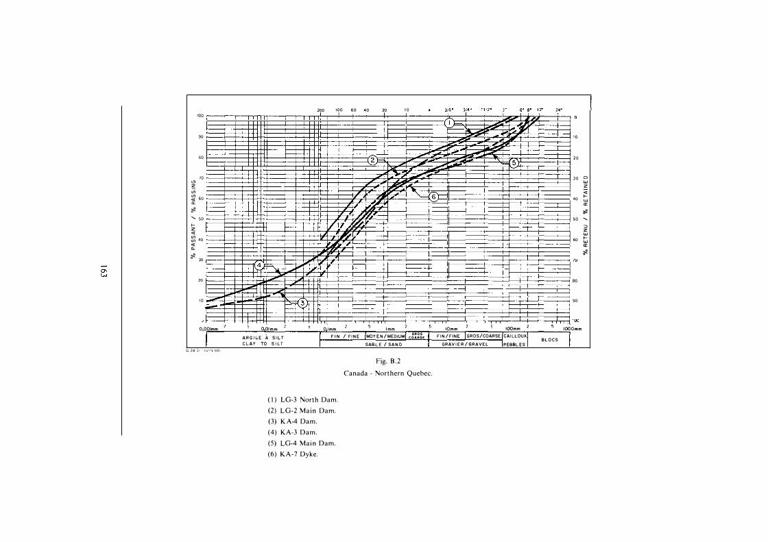
100
90
80
70"' z (/) (/) 60<( a_ � ' 50f-z <( � 40<( a_
� 30
20
10
O,OOlmm
G 24 3 1 ' J U • \J 8 0 :
4
oormm 2 ARG I LE À S I LT CLAY TO S I LT
3
200 100 60 40 1
• I
20 1
I • -• I __ , ,
I I I I ,r,r1
,
O lmm lmm MOYEN/MEDIUM SABL E / SAN O
F I N / FI N E
1 0
GROS COARSE
6
Fig. B . 2
Canada - Northern Quebec.
( 1 ) LG-3 North Dam.
(2) LG-2 Main Dam.
(3) K A-4 Dam.
(4) KA-3 Dam.
(5) LG-4 Main Dam.
(6) KA-7 Dyke.
IOmm FIN / FINE
IOOmm 2
GROS/COARSE CAI LLOUXGRAV I E R / GRAVEL PEBBL ES
24" '
BLOCS
10
20
30
40
50
60
80
90
IOOOmm
0wz<(f-wa:� 0 ' �zwf-wa:�

0,00lmm O Ol m m 2 A R G I L E À S I LT
C L A Y TO S I LT
Name of the dam.
( 1 ) Long Spruce. (2) Squaw Rapid.
200
1
100 60 40 1
� I
20 10
O i m m l mm
F I N / F I N E MOY E N / M E DI U M
SAB L E / S A N D
Fig. B . 3
GROS COARSE
J1a• 314 � 1 1 1 2 ·• J" 6" 8" 1 2" 24" ' 1 1
.-1
IOOmm 2 IOmm
F I N / F I NE GROS/COARSE C A I L L O U X
G R A V I E R / G R A V E L PEBBL E S B L O C S
Canada - Manitoba and Saskatchewan.
> O
20
JO 0
w
z
<(
40 r-w a::
;;?. so
::0 z w
60 r-w a::
;;?. 70
80
90
> OO
IOOOmm

°' V1
1 00
90
80
70 "' z
(f) (f)
60 <t ()._
� ' 50 >--z <t
� 40
<t ()._
200 100
3 A
I "
1 1
, I
60 40 20 10 1
t----t--1--+-r-t-++-t+--+--+-1-+-t--r.'''-+-�--r--+-- � 51. 1 r
1-------t-f-+---t-++-f+---+--+-�'+-+'-+-- : �--ri:Z=!...,," >-----+--+-+->-+++-++--+----+,-,1-+-!--4-C-+-�--+- Il t----t---+-l--+-++t-t+----+--<1---+-+-+ J__ � 3 B
, ,
- r
318" 314 " 1 1 /2'' 3" 6" 8' , ,. 24" 1 1 1
r , -
1 0
,, 20
JO 2
40
50
60
� r---+---t..-t-++-+++t-- -t--boo"!-t-+-h->�-+--,::::::::r===�--�----,-�'t---r--4---+-+--+---+-�--+-� 30 ,,
�
20
1 0
opo1mm
' ! U • N 801
OO lmm 2 ARG I L E À S ! LT CLAY TO S ! LT
Name of the dam. Nom du barrage. ( 1 ) Three Sisters. (2) Bighorn. (3) Brezeau. (4) Mica. (5) Revelstoke.
O lmm F I N / FI N E
lmm MOY E N /MEDIUMSAB L E / SAND
Fig. B.4
G R O S C O A R S E
IOmm IOOmm 2 F I N / F INE GROS/COARSE CAILLOUX GRAV I E R / GRAVEL PEBBL E S
Canada - Alberta and British Columbia.
Alberta et Colombie Britannique.
70
80
90
100 IOOOmm
B LOCS
0
w
z
<t >--
w a::
� ' ::;) z w >--w a::
�

1 00
90
80
70 "' z (/) (/) 60 rt_ 'if!. ...... 50 f-z <t � 40 <t Q.
'if!. 30
20
10
OiOOlmm
G·24 ::; 1 1 J U I N 8 0 1
O Olmm 2
ARG I L E À S IL T CLAY TO S I LT
Name of the dam. ( 1 ) Arstaddalen. (2) Tunhovd. (3) Hyttej u vet. (4) Sonstevatn.
•' ,
200 l'i" 60 40 20 10 J18 • 3/4 - 1 1 12t1 3• 1
5• a• 1 1
� 1 ·' ,1 4 ' ,,, _, . ,,,
... _ ,, - -
,,, ...... ,, .
''2' · "' JI �
,,,, ,.. - ,,, ,. .- ,.,,. .
,. - ,,, .-....
- 5 I ,, ,,
.1 ,. , ., ,. 11 - - ,
_1r3 ' - -- ,,
,, I
O lmm F I N / FI N E
lmm MOYEN/MEDIUMSAB L E / SANO
GROS COARSE
Fig. B.5
Sweden and Norway.
I
7 I
IOmm IOOmm 2
F IN/ FINE GROS/COARSE CAi LLOUXGRAV I ER / GRAVEL PEBBLES
1 2' 24' ' '
.. ....... 61= 10
20
30 0 w z <t
40 f-w 0:: 'if!.
50 ......
:::> z w
60 f-w 0:: 'if!.
70
80
JOOOmm
B LOCS
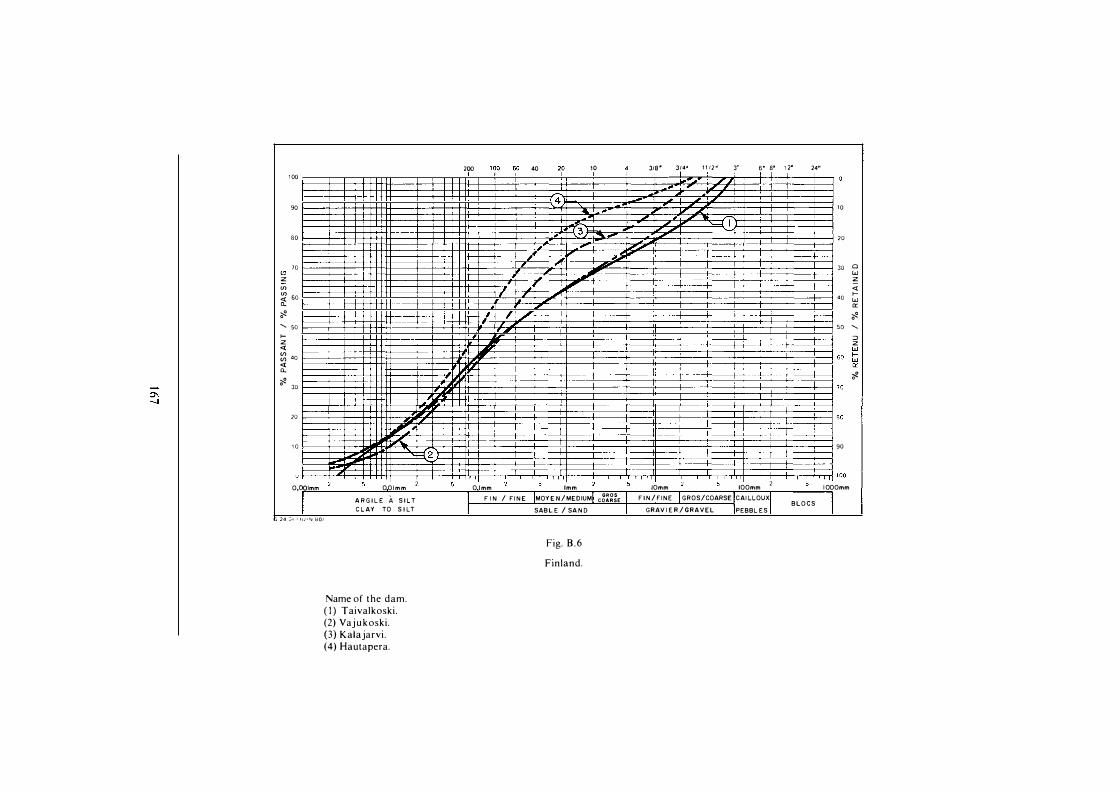
1 00
90
80
70 "' z (f) (f) 60 <t a. i<-' 50>--z <t � 40 <t a.
i<- 30
20
1 0
200 "?0 60 40 2,0 1 0 31a •
-
4 ...
, 3 -·
.· ,. ,�
I , ,,
--,, ,
-,. ., ,
.
1.
314• 1 1 12 � 3" 1 1
,, Il , 1 I ,, •' I
- �
5• s� 1 2• 24" 1 1 1 1
10
20
30
40
50
Clwz<t>w0::i<-':::>z
��������6
0
� t==t= 'il-�==t=:t::t:t::tl+tl====��,,��::tr:::t::=t:==:t==!:===J:t===:!====:!====ti===:!::===:t===::!=J:=:::!:=j::=::t::===!::=:j rn
��·� �����80
- 2 90
!�����iïl!��������������������������������������������� f--�-f-...L+-+--f-+++++-��+--+--l-+-Hfln+---'-,--'�--,l-,-,-,-,1,J��-+�r-,-l,;-r-,--,-,J+-��t,.-�---.J,��,.J,..,+----'--l�-H-,-�i-.-.......1 1 00
O,OOlmm OOlmm 2 O lmm lmm MOYEN/MEDIUMSABL E / SAN D
IOmm IOOmm 2 I OOOmm
G 24 ::; 1 1 J LJ • N 801
ARG I L E À S I L T CLAY TO S I LT
Name of the dam. ( 1 ) Taivalkoski. (2) Vajukoski. (3) Kalajarvi. (4) Hautapera.
F I N / FI NE
Fig. B .6
Fin land.
GROS COARSE F I N/FINE GROS/COARSE CAI LLOUX BLOCS
GRAV I E R / GRAVEL PEBBL ES

2?" 190 60 •.o 2.0 10 318" 314" 1 1 12'' 3" 5• s• 1 2" 24'' 100 1 1 1
" 1
90 10
.-80 20
70 JO Cl "' - LU z � z Cf) 7 <{ Cf) 60 f-<{ 40 LU "- ,, 1 a: � 1 � ' 50 7 50 f- :::J z z <{ T LU � 40 60 f-LU °' <{ a: OO "-� �
30 70
fi' 20 I 80
,
1 0 90
----+--
1 1 1 00 O,OOlmm O OJmm 2 O lmm lmm IOmm IOOmrn IOOOmm
AR G 1 L E À S I L T F 1 N / F INE MOYE N /MEDIUM GROS F I N / FINE GROS/COARSE CAILLOUX COARSE B LOCS CLA 1 TO S 1 LT SAB L E / SA N D GRAV I E R / GRAVEL PEBBL ES
G 2 4 ::; 1 I U ' '\j S ü i
Fig. B.7
New-Zealand - Pukake Dam.

"' z
100 ��---.�.-,-..,rrTT-rr��,.--,---,-r-r-,2�?_0,.--147_0�46o�-•+?��4�0���1�0��-+���431�a-· �-';�·-· �-1�1 11 _, _" ���-" ,.,--+�-" 4B_'__,1_2·��'�•-" �
0,00lmm O Olmm ARG I L E À S I L T CLAY TO S I LT
Name of the dam. ( 1 ) Knyazhegubsk.
O lmm tmm F I N / FI NE MOY E N /MEDIUM
SAB LE / SAN D
Fig. 8 .8
USSR.
(2) Lyakhkominsk and Tupegubsk. (3) lorsk. (4) Kumks. (5) Tolvanks.
G R O S C O A R S E
IOOmm 2 lümm FIN /FINE GROS/COARSE CAILLOUX GRAV IER / GRAVEL PEBBL ES
BLOCS
1 0
20
30
40
50
60
70
80
100 IOOOmm
0
w
z
<l f-w a:
� ::0 z w f-w a:
�

100
90
80
70 "' z <f) <f) 60 � � ' 50 f-z <( � 40 <( a. � 30
20
1 0
O,OOlmm
G :'4 ::; 1 1 J U I N 801
O Olmm 2
A R G I L E À S I L T C LAY TO S 1 LT
Name of the dam. ( l ) Grand'Maison. (2) Mont-Cenis.
290 100 60 40 2,0 101
T
t+-- "" ' "
CT ,.
/ 7 / /1 .A
,
- ,, ,, " -
O lmm lmm
F I N / F I N E MOY E N / MEDIUM GROS COARSE
SAB L E / SA N D
Fig. B.9
France.
J1a• 314 " 1 1 1 2 " 3" s· B' 12• 24" 1 1 1 1/ "
,
, " 1 0,
, , ,
20
, 30 0 w , z
IF ., <( ,., f-40 w
,, 0: , ,,, r � ,, 50
::J z w 60 f-w 0: �
70
80
90
100 IOmm IOOmm 2 IOOOmm
F I N /F INE GROS/COARSE CAILLOUX BLOCS
GRAV I E R / GRAVEL PEBB L E S

I mprimerie de Montl igeon 6 1 400 La Chapelle Montligeon
Dépôt légal : janvier 1 989 No 1 4 1 77
lSSN 0534-8293 Couverture : Olivier Magna

Copyright © ICOLD - CIGB
Archives informatisées en ligne Computerized Archives on line
The General Secretary / Le Secrétaire Général : André Bergeret - 2004
_______________________________________________________________
International Commission on Large Dams Commission Internationale des Grands Barrages 151 Bd Haussmann -PARIS –75008
http://www. icold-cigb.net ; http://www. icold-cigb.org