morphology development of an airfoil by numerical...
TRANSCRIPT

ICAST2014: 25nd International Conference on Adaptive Structures and Technologies October 6-8th, 2014, The Hague, The Netherlands
1
ICAST2014 #024
Morphology development of an airfoil by numerical analysis
M. A. Carrizales Rodríguez, M. Castillo Morales
Facultad de Ingeniería Mecánica y Eléctrica, Universidad Autónoma de Nuevo León, Avenida Universidad s/n, Ciudad Universitaria, San Nicolás de los Garza, Nuevo León, México, C.P. 66451.
Abstract
As aerial application is not quite feasible for small croplands with current aircrafts in the market, because their higher
operational speed. An adequate solution is to generate morphology in the airfoil of the wing of an aircraft, that would
allow to decrease the operational speed of the aircraft by increasing the lift that the wing can generate at lower speed
without the issue of reach the stall speed. Different airfoils were evaluated in order to compare their characteristics of
high-lift and low Reynolds number with those of the NACA 4415, which is the current airfoil of the chosen agricultural
aircraft. Such evaluation was carried out by numerical analysis in two dimensions, using Computational Fluid
Dynamics software (CFD) at the same air conditions. It is observed that some airfoils obtain much better lift, compare
with the base airfoil, but the geometry became very complex. The GOE 449 airfoil was selected due to the minimum
geometric changes to do in order to perform the morphology from the original airfoil obtaining 26% more lift. In order
to obtain the minimum geometric changes as possible in the morphology from the NACA 4415 airfoil to seek the GOE
449 lift performance a new airfoil was obtained. The aerodynamics properties of this airfoil, called FUSION, are close
to the GOE 449 airfoil, obtaining a 7% less lift. It is expected to substitute the use of any auxiliary mechanism like
flaps, slats or airbrakes, using smart materials in order to increase the operational capacities of the aircraft and replace
the weight of this by payload.
1. Introduction
The morphology applied to an aircraft is not a new subject in aeronautics, but in recent times it has been
retaken by the development of new materials, sensors, microelectronics and support systems[1].
The first design that attempt to emulate the flight of the bird was made by Leonardo Da Vinci, by a
rigorous analysis of the mechanics of bird flight [2]. Nowadays whit the development of modern aviation
and in particular in World War II, aircrafts whit some type of mechanical morphology appear like the F4U
“Corsair” that can fold their wings for easy storage on the aircraft carries[3], other designs were made by
the Luffwafe with the Me 1102/5 that was a concept of a jet bomber capable of change the sweep angle of
the wing in flight, a similar morphology was used in the Me P.1101 prototype capable of change the sweep
angle of the wing from 35 to 45 degrees on ground[4].
A the end of the war the American Army took possession of the Me P.1102/5 and whith the aid of NASA
and Bell aircraft corporation, the X-5 was developed and became the first aircraft capable of change the
sweep angle in flight. From these programs the F-111 “Aardvark” and the F-14 “Tomcat” were born[5].
In the late 80’s and the early 90’s, NASA developed 2 coordinate programs that were aimed to research
new technologies that involucrate different areas, “The NASA aircraft morphing program”[6] and “The
mission adaptive wing program”[7]. In these programs were used for the first time smart materials.

ICAST2014: 25nd International Conference on Adaptive Structures and Technologies October 6-8th, 2014, The Hague, The Netherlands
2
In 2002 the DARPA launched a program aimed to develop an aircraft whit morphing structures the
“Morphing aircraft Structures (MAS)” was born. The main objective of the program was to investigate the
capability of an aircraft to change the shape of its wing in order to increase its aerodynamic efficiency[1].
In this program only 2 prototypes were able to change the geometry of the entire wing one from Lockheed-
Martin[8] and other from NextGen[9].
The aircraft morphology can be classified depending in what is the target of the change Fig.1.[10].
In this research work, the aim is focus on making the morphology in the upper camber of the airfoil, and
in this particular area most of the research have been made changing the leading edge of the airfoil using
smart materials, using Macro-Fiber Composite (MFC)[11], Electric Active Polymer (EAP)[12], Post-
Buckled Pre-compressed Piezoelectric (PBP)[13], Lightweight Piezo-composite Curved Actuator
(LIPCA)[14] and shape memory alloys[15, 16].
The objective to make a morphology on an aircraft, more precisely in the upper camber of an agricultural
aircraft, is because the work speed to perform an aerial application is too high, leaving farmers whith less
that 10 Ha out of this service[17]. A solution to this issue is to make the change from the original airfoil,
that the aircraft have, to another airfoil whith specific characteristics like high lift and low flight speeds[18],
by doing this the lift required can be obtained at lowers speeds, being able to access small farming areas.
2. Aerial application analysis parameters
According to Food and Agriculture Organization of the United Nations (FAO), some general parameters
in aerial application need to be taken into consideration [19]. For this research work the standard atmosphere
is considered at Monterrey Sea Level, and the working conditions used in this work are showing in table 1.
Aircraft Morphing
Structured Wing
Platform
Telescoping Sweep
Out-of-Plane
Folding Camber Twist Winglets Skin
Inflatable Wing
Figure 1. Categories of morphing wing in aircraft.

ICAST2014: 25nd International Conference on Adaptive Structures and Technologies October 6-8th, 2014, The Hague, The Netherlands
3
Table 1 Operational Conditions for Aerial Application based on standard atmosphere, considered in the
numerical analysis
Parameters Value Units
Altitude 600 m
Density 1.155978 Kg/m3
Atmospheric Pressure 94323.87 N/m2
Viscosity 1.77049 e-5 N*s/m2
Airfoil Cord 2.07 m
Working Speed 66.59318 m/s
Reynolds Number 9 e 6
Mach Number 0.197
2.1 Numerical analysis results versus the experimental analysis results
In order to validate the numerical analysis results obtained from CFD software is necessary to compare
with experimental results obtained from wind tunnel test published in literature as Ira H. Abbot [20]. The
airfoil to be analyzed, which is used by the aerial application aircraft, is the NACA 4415. Table 2 shows the
parameters selected to carry out the numerical analysis considering the standard atmosphere.
Table 2 Wind Tunnel Parameters considered in the numerical analysis of the NACA 4415
Parameters Value Units
Altitude 0 M
Density 1.225 Kg/m3
Atmospheric Pressure 101327.3 N/m2
Viscosity 1.78372 e-5 N*s/m2
Airfoil Cord 1 M
Working Speed 51.05 m/s
Reynolds Number 3.49 e 6
Mach Number 0.15

ICAST2014: 25nd International Conference on Adaptive Structures and Technologies October 6-8th, 2014, The Hague, The Netherlands
4
As many CFD computational programs are used to acquire data in scientific papers, it was
decided to perform the analysis results in three of them ANSYS FLUENT, Design Foil (Demo Version),
and XFL 5 (Free Software), in order to obtain the best approximation to the experimental data, each one of
these use the same input parameters and good results have been obtained as shown in Fig.2.
All of the software shows a good approximation to the experimental data within the linear zone of
the graph Lift Coefficient (CL) versus Angle of Attack (AOA). Making a comparison among these
software, in the linear zone is observed that the data obtained from ANSYS FLUENT has the minimum
percentage of error to the experimental data, the percentage of error for each program is shown in Table 3.
Table 3 Percentage of error among experimental data and numerical analysis data from different software
programs for the NACA 4415 airfoil
Experimental Data
Average Error
Linear Zone
Design Foil ANSYS FLUENT XFL 5
5.97% 2.32 % 3.18%
3. Airfoil Selection process for morphology
In order to achieve the change in geometry of the NACA 4415 to improve the aerodynamics properties an
airfoil selection must be carry out to match the necessities set by the operation of the aircraft. The selected
airfoil must fit the important aspects seek to improve the NACA 4415, such as lowers working speeds and
a greater lift force, these airfoils are within the group of low Reynolds number.
A group of 81 airfoils, classified airfoils of low Reynolds number, were selected using the UIUC Airfoil
Data Base [21] from the University of Illinois. These airfoils are showed in Table 4.
Figure 2. 𝐶𝐿 vs AOA graph, comparison among experimental data and numerical analysis for the
NACA 4415 airfoil.

ICAST2014: 25nd International Conference on Adaptive Structures and Technologies October 6-8th, 2014, The Hague, The Netherlands
5
Table 4 Airfoils of low Reynolds number selected from [21]
A18 E171 E423 FX76-120 GOE 289 GOE 449 K3311 S1223 RTL USA 35B
Apex 16 E174 Falcon FX76-140 GOE 386 GOE 418A MB253515 S2048
Aquila E176 FX05-188 FX76-160 GOE 390 GOE 498 MH113 S2050
Avistar E178 FX60-100 FX83-108 GOE 398 GOE 508 Miley S2091
CH10 S E180 FX60-100S FX83-160 GOE 404 GOE 523 N-24 S4020
DF102 E182 FX60-126 Gemini S GOE 413 GOE 527 NACA 2414 S4233
DH4009S E184 FX63-137 GOE 225 GOE 420 GOE 533 NACA 2415 S8036
DU86-084 E201 FX69-281 GOE 234 GOE 433 GOE 534 RG-15 SA7035
E168 E210 FX73-152 GOE 241 GOE 441 GOE 612 S1210 SD6080
E169 E220 FX74-140 GOE 288 GOE 446 GOE 798 S1223 USA 34
The procedure to select the airfoil required for this work is achieving as follows:
𝐶𝐿 selection.
Geometric selection.
𝐶𝐷 selection.
The software used to obtain numerical information from each airfoil is “Design Foil” due to the short
period of time required to obtain results.
3.1 CL selection
In order to improve the Lift force given by the NACA 4415 the new suggested airfoil must give the same
Lift force with a lower operational speed, meeting the following statement in the linear zone of the
𝐶𝐿 𝑣𝑠 𝐴𝑂𝐴 chart:
𝐿 =1
2𝜌𝑉2𝑆𝐶𝐿 1
Where L is the Lift force, is the density, V the velocity, and S the Surface.
If
𝐿𝐵𝑎𝑠𝑒 = 𝐿𝐶𝑎𝑛𝑑𝑖𝑑𝑎𝑡𝑒 𝜌 = 𝑐𝑜𝑛𝑠𝑡𝑎𝑛𝑡 𝑆 = 𝑐𝑜𝑛𝑠𝑡𝑎𝑛𝑡

ICAST2014: 25nd International Conference on Adaptive Structures and Technologies October 6-8th, 2014, The Hague, The Netherlands
6
Where LBase is the Lift force of the NACA 4415 airfoil and the LCandidate is the Lift force of the suggested
airfoil: Then
𝑉 = √2𝐿𝐵𝑎𝑠𝑒
𝜌𝑆𝐶𝐿𝐶𝑎𝑛𝑑𝑖𝑑𝑎𝑡𝑒
2
Where V is the velocity, so the following statement is:
𝑉𝑐𝑎𝑛𝑑𝑖𝑑𝑎𝑡𝑒 < 𝑉𝐵𝑎𝑠𝑒 ∴ 𝐶𝐿𝐶𝑎𝑛𝑑𝑖𝑑𝑎𝑡𝑒 > 𝐶𝐿𝐵𝑎𝑠𝑒
Where the selected airfoil must give higher CL at lower velocities, compared to the NACA 4415.
After the CL selection, only 29 airfoils met the stated condition. Three groups were formed from the
selected airfoils according to the magnitude of the CL compared to the NACA 4415. Fig. 3.
3.2 Geometric comparison
From the 29 airfoils selected by CL magnitude, considering the most approaching geometry to the NACA
4415 the geometric selection is carried out. The changes are considering achieving the morphology from
the original airfoil to the selected one. The aim in this section is to avoid the complicated shapes of the
selected airfoil that can originate a sophisticated and too complex morphology design in the airfoil as seen
in Fig. 4a, and select the airfoils with shapes similar to the NACA 4415 airfoil as seen in Fig. 4b.
Figure 3. Group of selected airfoils showing a better lift coefficient in comparison to the base airfoil
(NACA 4415); a) Group of selected airfoils with the highest CL., b) Group of selected airfoils with
a moderated CL., c) Group of selected airfoils with slightly higher CL.

ICAST2014: 25nd International Conference on Adaptive Structures and Technologies October 6-8th, 2014, The Hague, The Netherlands
7
At this stage, 12 airfoils were chosen; most of them are from the third group of the CL selection. Table 5
shows the airfoils selected, which fits with the purpose of this stage.
Table 5 List of candidate’s airfoil’s whit adequate geometric change
Fx83-108 GOE 288 GOE 289 GOE 390
GOE 398 GOE 413 GOE 446 GOE 449
GOE 508 GOE 527 GOE 612 GOE 798
3.3 Drag coefficient selection
The CD selection is done similar to the CL selection. It is seek the less possible amount of the drag force
obtained from the suggested airfoil compared to the NACA 4415 airfoil. From the drag equation:
𝐷 =1
2𝜌𝑉2𝑆𝐶𝐷 3
Where D is the Drag force.
If
𝐷𝐶𝑎𝑛𝑑𝑖𝑑𝑎𝑡𝑒 ≤ 𝐷𝐵𝑎𝑠𝑒 𝜌 = 𝑐𝑜𝑛𝑠𝑡𝑎𝑛𝑡 𝑆 = 𝑐𝑜𝑛𝑠𝑡𝑎𝑛𝑡
Where DCandidate is the Drag force of the suggested airfoil, and DBase is the Drag force of the NACA 4415
airfoil, the next equation is obtained:
𝑉 = √2𝐷𝐶𝑎𝑛𝑑𝑖𝑑𝑎𝑡𝑒
𝜌𝑆𝐶𝐷𝐶𝑎𝑛𝑑𝑖𝑑𝑎𝑡𝑒
4
Figure 4. a). Airfoils with a complex geometry to achieve, b). Airfoils with geometry not too
complex to achieve.
ICAST2014: 25nd International Conference on Adaptive Structures and Technologies October 6-8th, 2014, The Hague, The Netherlands
8
So
𝑉𝑐𝑎𝑛𝑑𝑖𝑑𝑎𝑡𝑒 < 𝑉𝐵𝑎𝑠𝑒 ∴ 𝐶𝐷𝐶𝑎𝑛𝑑𝑖𝑑𝑎𝑡𝑒 < 𝐶𝐷𝐵𝑎𝑠𝑒
Where CD Candidate is the Drag coefficient of the suggested airfoil, and the CD Base is the Drag coefficient of
the NACA 4415 airfoil.
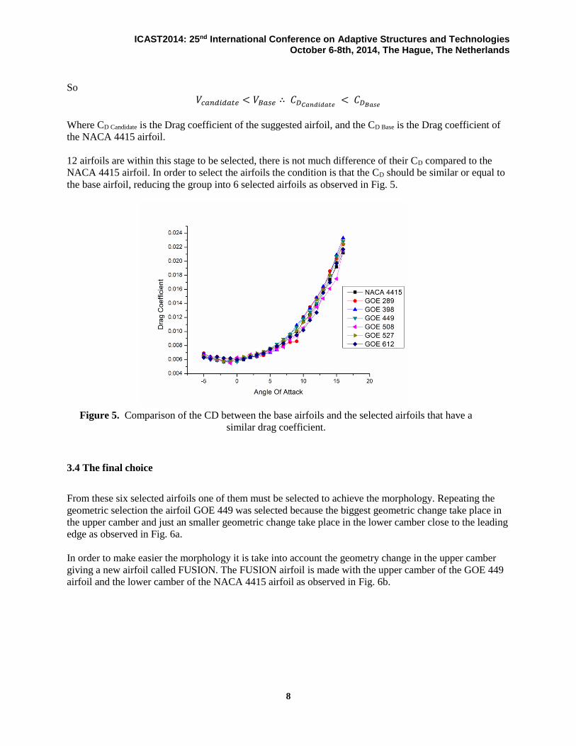
12 airfoils are within this stage to be selected, there is not much difference of their CD compared to the
NACA 4415 airfoil. In order to select the airfoils the condition is that the CD should be similar or equal to
the base airfoil, reducing the group into 6 selected airfoils as observed in Fig. 5.
3.4 The final choice
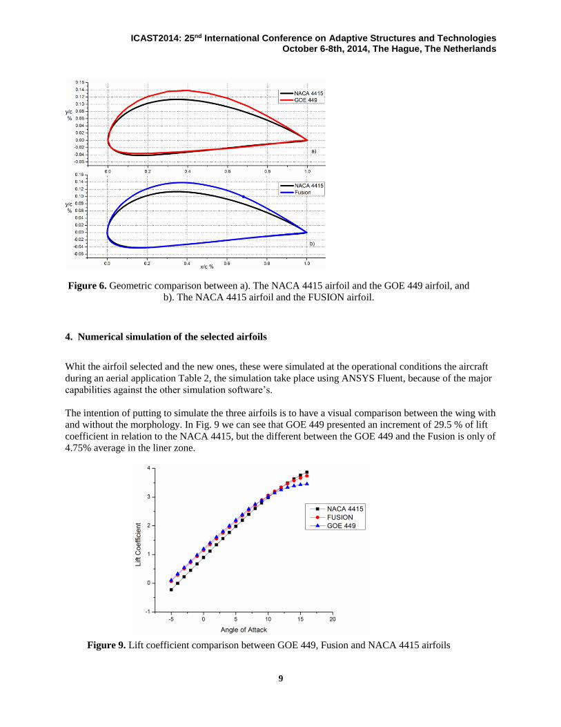
From these six selected airfoils one of them must be selected to achieve the morphology. Repeating the
geometric selection the airfoil GOE 449 was selected because the biggest geometric change take place in
the upper camber and just an smaller geometric change take place in the lower camber close to the leading
edge as observed in Fig. 6a.
In order to make easier the morphology it is take into account the geometry change in the upper camber
giving a new airfoil called FUSION. The FUSION airfoil is made with the upper camber of the GOE 449
airfoil and the lower camber of the NACA 4415 airfoil as observed in Fig. 6b.
Figure 5. Comparison of the CD between the base airfoils and the selected airfoils that have a
similar drag coefficient.
ICAST2014: 25nd International Conference on Adaptive Structures and Technologies October 6-8th, 2014, The Hague, The Netherlands
9
4. Numerical simulation of the selected airfoils
Whit the airfoil selected and the new ones, these were simulated at the operational conditions the aircraft
during an aerial application Table 2, the simulation take place using ANSYS Fluent, because of the major
capabilities against the other simulation software’s.
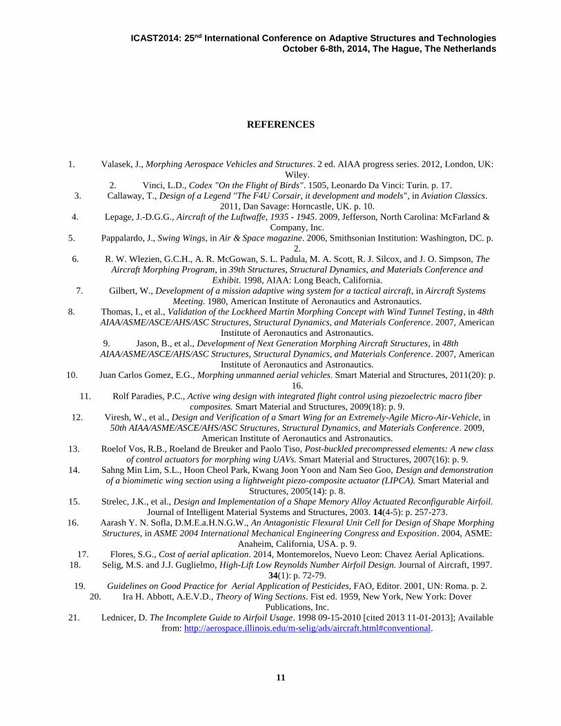
The intention of putting to simulate the three airfoils is to have a visual comparison between the wing with
and without the morphology. In Fig. 9 we can see that GOE 449 presented an increment of 29.5 % of lift
coefficient in relation to the NACA 4415, but the different between the GOE 449 and the Fusion is only of
4.75% average in the liner zone.
Figure 9. Lift coefficient comparison between GOE 449, Fusion and NACA 4415 airfoils
Figure 6. Geometric comparison between a). The NACA 4415 airfoil and the GOE 449 airfoil, and
b). The NACA 4415 airfoil and the FUSION airfoil.

ICAST2014: 25nd International Conference on Adaptive Structures and Technologies October 6-8th, 2014, The Hague, The Netherlands
10
Another think that we saw is at high AOA the GOE 449 drop faster unlike the FUSION that almost
maintain equal to the NACA 4415.
In terms of the operational speed, the lift force generated by the NACA 4415 in the simulation level fly is
of 127.9107𝑥103 𝑁, applying the lift force equation and the but the lift coefficients of the GOE 449 and
FUSION instead of the NACA 4415, it can be calculate the new operational speed of the aircraft has
shown in Table 6.
Table 6 Speed require for operational conditions for each airfoil
Airfoil Lift Force (N) Lift
Coefficient Operational Speed (m/s)
NACA 4415
127.9107x(10)^3 1.339 66.593
GOE 449 127.9107x(10)^3 1.552 60.766
FUSION 127.9107x(10)^3 1.608 61.863
So it is possible to reduce the speed of the operation, by making a morphology, in this particular case the
reduction is only of 8.75% for the GOE 449 and of 7.10 % for FUSION meaning only a difference of 2%.
For this reason and that only the upper surface have to change, the FUSION airfoil is the one to make the
morphology aircraft wing.
5. Conclusions
Throughout this work an evaluation of airfoils to improve the aerodynamics of the actual airfoil has been
done selecting one, which is similar to the actual airfoil in order to have the improvements without
complicated geometric changes. It is observed that:
Making a change from a base airfoil in the wing by a morphology valid way to change the mission
speed of a particular aircraft
At this moment by lack of manufacture we have to choose an airfoil that we gain little speed.
ACKNOWLEDGMENTS
The authors gratefully acknowledge the financial support of CONACyT, PROMEP and the FIME-UANL
ICAST2014: 25nd International Conference on Adaptive Structures and Technologies October 6-8th, 2014, The Hague, The Netherlands
11
REFERENCES
1. Valasek, J., Morphing Aerospace Vehicles and Structures. 2 ed. AIAA progress series. 2012, London, UK:
Wiley.
2. Vinci, L.D., Codex "On the Flight of Birds". 1505, Leonardo Da Vinci: Turin. p. 17.
3. Callaway, T., Design of a Legend "The F4U Corsair, it development and models", in Aviation Classics.
2011, Dan Savage: Horncastle, UK. p. 10.
4. Lepage, J.-D.G.G., Aircraft of the Luftwaffe, 1935 - 1945. 2009, Jefferson, North Carolina: McFarland &
Company, Inc.
5. Pappalardo, J., Swing Wings, in Air & Space magazine. 2006, Smithsonian Institution: Washington, DC. p.
2.
6. R. W. Wlezien, G.C.H., A. R. McGowan, S. L. Padula, M. A. Scott, R. J. Silcox, and J. O. Simpson, The
Aircraft Morphing Program, in 39th Structures, Structural Dynamics, and Materials Conference and
Exhibit. 1998, AIAA: Long Beach, California.
7. Gilbert, W., Development of a mission adaptive wing system for a tactical aircraft, in Aircraft Systems
Meeting. 1980, American Institute of Aeronautics and Astronautics.
8. Thomas, I., et al., Validation of the Lockheed Martin Morphing Concept with Wind Tunnel Testing, in 48th
AIAA/ASME/ASCE/AHS/ASC Structures, Structural Dynamics, and Materials Conference. 2007, American
Institute of Aeronautics and Astronautics.
9. Jason, B., et al., Development of Next Generation Morphing Aircraft Structures, in 48th
AIAA/ASME/ASCE/AHS/ASC Structures, Structural Dynamics, and Materials Conference. 2007, American
Institute of Aeronautics and Astronautics.
10. Juan Carlos Gomez, E.G., Morphing unmanned aerial vehicles. Smart Material and Structures, 2011(20): p.
16.
11. Rolf Paradies, P.C., Active wing design with integrated flight control using piezoelectric macro fiber
composites. Smart Material and Structures, 2009(18): p. 9.
12. Viresh, W., et al., Design and Verification of a Smart Wing for an Extremely-Agile Micro-Air-Vehicle, in
50th AIAA/ASME/ASCE/AHS/ASC Structures, Structural Dynamics, and Materials Conference. 2009,
American Institute of Aeronautics and Astronautics.
13. Roelof Vos, R.B., Roeland de Breuker and Paolo Tiso, Post-buckled precompressed elements: A new class
of control actuators for morphing wing UAVs. Smart Material and Structures, 2007(16): p. 9.
14. Sahng Min Lim, S.L., Hoon Cheol Park, Kwang Joon Yoon and Nam Seo Goo, Design and demonstration
of a biomimetic wing section using a lightweight piezo-composite actuator (LIPCA). Smart Material and
Structures, 2005(14): p. 8.
15. Strelec, J.K., et al., Design and Implementation of a Shape Memory Alloy Actuated Reconfigurable Airfoil.
Journal of Intelligent Material Systems and Structures, 2003. 14(4-5): p. 257-273.
16. Aarash Y. N. Sofla, D.M.E.a.H.N.G.W., An Antagonistic Flexural Unit Cell for Design of Shape Morphing
Structures, in ASME 2004 International Mechanical Engineering Congress and Exposition. 2004, ASME:
Anaheim, California, USA. p. 9.
17. Flores, S.G., Cost of aerial aplication. 2014, Montemorelos, Nuevo Leon: Chavez Aerial Aplications.
18. Selig, M.S. and J.J. Guglielmo, High-Lift Low Reynolds Number Airfoil Design. Journal of Aircraft, 1997.
34(1): p. 72-79.
19. Guidelines on Good Practice for Aerial Application of Pesticides, FAO, Editor. 2001, UN: Roma. p. 2.
20. Ira H. Abbott, A.E.V.D., Theory of Wing Sections. Fist ed. 1959, New York, New York: Dover
Publications, Inc.
21. Lednicer, D. The Incomplete Guide to Airfoil Usage. 1998 09-15-2010 [cited 2013 11-01-2013]; Available
from: http://aerospace.illinois.edu/m-selig/ads/aircraft.html#conventional.