motorized stage/controller/cable sets - photon lines france · compatible controller gsc-01,...
TRANSCRIPT
G026
Mot ion Cont ro l Products
Guide
Controllers/Drivers
Softwares
AC Servo Motor
Cables
Piezo
X Translation
Theta Rotation
Goniometer
Vacuum
Options
□40mm
□60mm
□80mm
□85mm
□100mm
□120mm
Others
Application Systems
Optics & Optical Coatings
Holders
Bases
Manual Stages
Actuators
Motoeized Stages
Light Sources
Index
Stepping Motor
Motorized Stage/Controller/Cable Sets
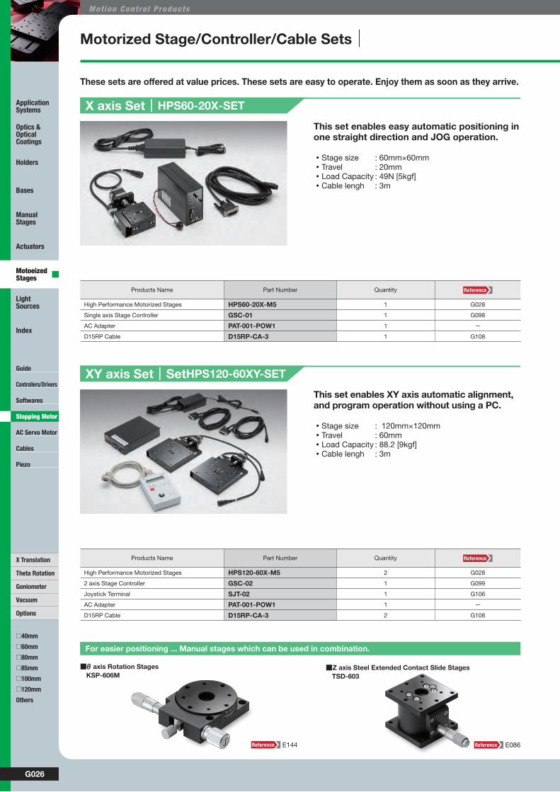
This set enables easy automatic positioning in one straight direction and JOG operation.
These sets are offered at value prices. These sets are easy to operate. Enjoy them as soon as they arrive.
This set enables XY axis automatic alignment, and program operation without using a PC.
・Stage size : 60mm×60mm・Travel : 20mm・Load Capacity : 49N [5kgf]・Cable lengh : 3m
・Stage size : 120mm×120mm・Travel : 60mm・Load Capacity : 88.2 [9kgf]・Cable lengh : 3m
X axis Set|HPS60-20X-SET
XY axis Set|SetHPS120-60XY-SET
Products Name Part Number Quantity
High Performance Motorized Stages HPS60-20X-M5 1 G028
Single axis Stage Controller GSC-01 1 G098
AC Adapter PAT-001-POW1 1 ー
D15RP Cable D15RP-CA-3 1 G108
Products Name Part Number Quantity
High Performance Motorized Stages HPS120-60X-M5 2 G028
2 axis Stage Controller GSC-02 1 G099
Joystick Terminal SJT-02 1 G106
AC Adapter PAT-001-POW1 1 ー
D15RP Cable D15RP-CA-3 2 G108
■θ axis Rotation Stages KSP-606M
■Z axis Steel Extended Contact Slide Stages TSD-603
For easier positioning ... Manual stages which can be used in combination.
E144 E086

G027WEB http://www.sigma-koki.com/english/ E-mail [email protected] TEL +81-3-5638-8228 FAX +81-3-5638-6550
Guide
Controllers/Drivers
Softwares
AC Servo Motor
Cables
Piezo
X Translation
Theta Rotation
Goniometer
Vacuum
Options
□40mm
□60mm
□80mm
□85mm
□100mm
□120mm
Others
Application Systems
Optics & Optical Coatings
Holders
Bases
Manual Stages
Actuators
Motoeized Stages
Light Sources
Index
Stepping Motor
Motorized stage system for minute positioning and angle adjustment such as for marking of semiconductor wafers.
This set is best suited for measuring and inspection equipment and for XYZ axis automatic positioning of workpieces.
・It can be controlled externally using Ethernet/RS232C/USB interface.Also, the number of axes is extendable by adding slave controllers (Part Number: HIT-S).
・Stage size : φ120mm・Travel : ±6° [θ axis] : 60mm [XY axis]・Load Capacity : 58.8N [6kgf]・Cable lengh : 3m
◦It can be controlled externally using RS232C/GP-IB/USB interface, or manually using a joy stick (JS-300).
・Stage size : 60mm×60mm・Travel : 85mm [XY axis], 10mm [Z axis]・Load Capacity : 29.4N [3kgf]・Cable lengh : 3m
Xyθ axis Set|HPS/HDS120-XYθ-SET
XYZ axis Set|OSMS20-XYZ-SET
Products Name Part Number Part Number
High Performance Motorized Stages HPS120-60X-M5 2 G028
High durability automatic rotation stage HDS-120YAW 1 G080
Extensible Stage Controller (Master) HIT-M 1 G103
Extensible Stage Controller (Slave) HIT-S 3 G103
AC Adapter 1 ー
D15RP Cable D15RP-CA-3 3 G108
Products Name Part Number Part Number
OSMS Series Translation Motorized Stages - 5 Phase Stepping Motor OSMS20-85(X) 2 G032
Translation Motorized Stages, Flat Z axis - 5 Phase Stepping Motor OSMS60-10ZF 1 G070
4 axis Stage Controllers SHOT-304GS 1 G102
Joystick Terminal JS-300 1 G107
D15RP Cable D15RP-CA-3 1 G108
D15D15A Cable D15D15A-CA-3 2 G108
MDR14-CA-2.5 Cable MDR14-CA-2.5 1 G109
■Software for Positioning, Measurement & Analysis SGMACSE
■Software for Monitoring & Control SGVIEWE
Make it more convenient … Software for stage control
G022 G022
W9062CatalogCode

G028
Mot ion Cont ro l Products
Guide
Controllers/Drivers
Softwares
AC Servo Motor
Cables
Piezo
Theta Rotation
Goniometer
Vacuum
Options
□40mm
□85mm
□100mm
Others
Application Systems
Optics & Optical Coatings
Holders
Bases
Manual Stages
Actuators
Motoeized Stages
Light Sources
Index
□120mm
□80mm
□60mm
X Translation
Stepping Motor
High Performance Motorized Stages HPS
Motorized stages with ball screws offering middle/high performance at low price.
SpecificationsPart Number HPS60-20X-M5 HPS80-50X-M5 HPS120-60X-M5
MechanicalSpecifications
Travel [mm] 20 50 60
Table Size [mm] 60×60 80×80 120×120
Feed Screw Ball screw diameter φ6mm, 1mm lead
Ball screw diameter φ6mm, 1mm lead
Ball screw diameter φ6mm, 1mm lead
Positioning Slide Ball guide Ball guide Ball guide
Stage Material Aluminum Aluminum Aluminum
Finish Black anodized Black anodized Black anodized
Weight [kg] 0.6 1 1.5
AccuracySpecifications
Resolution (Full) [μm/pulse] 2 2 2
(Half) [μm/pulse] 1 1 1
MAX Speed [mm/sec] 10 10 10
Positioning Accuracy [μm] 15 25 25
Positional Repeatability [μm] ±1 ±2 ±2
Load Capacity [N] 49 (5kgf) 73.5 (7.5kgf) 98 (10kgf)
Moment Stiffness
Pitch [″/N・cm] 0.4 0.5 0.5
Yaw [″/N・cm] 0.4 0.5 0.5
Roll [″/N・cm] 0.3 0.2 0.2
Lost Motion [μm] 1 2 2
Backlash [μm] 1 2 2
Parallelism [μm] 30 40 50
Running Parallelism [μm] 10 10 10
Pitch [″] / Yaw [″] 25/25 30/25 30/25
Sensor
Sensor Part Number Micro photo sensor: GP1S097HCZ(Sharp Corporation)
Limit Sensor Equipped (NORMAL CLOSE) Equipped (NORMAL CLOSE) Equipped (NORMAL CLOSE)
Origin Sensor Equipped (NORMAL OPEN) Equipped (NORMAL OPEN) Equipped (NORMAL OPEN)
Proximity Origin Sensor None None None
Motor / Sensor Specifications
Motor
Type 5-phase stepping motor 0.75A/phase (Oriental Motor Co., Ltd.)
Motor Part Number PK523HPB-C12 (□28mm)
Step Angle 0.72°
Sensor
Power Voltage DC5 - 24V ±10%
Current Consumption 60mA or lower (20mA or lower per sensor)
Control Output NPN open collector output DC30V or lower, 50mAWhen load current is 16mA, the residual voltage is under 0.4V When load current is 50mA, the residual voltage is under 0.7V
Output Logic In the case of light shielded ,output transistor OFF (No conduction): Limit sensorIn the case of light shielded ,output transistor ON (Conduction): Origin sensor
Compatible Driver / Controller
Control SystemCompatible Driver SG-5M, SG-5MA, SG-55M, SG-55MA, SG-514MSC, MC-7514PCL
Compatible Controller GSC-01, GSC-02, SHOT-702, GIP-101, SHOT-302GS, SHOT-304GS, HIT-M・HIT-S, PGC-04
▶Please contact us when assembled into XYZ axis or use in reversion on the ceiling or vertical direction.
▶Opposite model or various motor changes are optionally available. G030
Guide
◦Ball screws with improved durability compared to the existing TSDM series.
◦Our original high precision integrated ball guide used in place of a cross roller guide makes it possible to offer a price lower than the TAMM series.
G029WEB http://www.sigma-koki.com/english/ E-mail [email protected] TEL +81-3-5638-8228 FAX +81-3-5638-6550
Guide
Controllers/Drivers
Softwares
AC Servo Motor
Cables
Piezo
Theta Rotation
Goniometer
Vacuum
Options
□40mm
□85mm
□100mm
Others
Application Systems
Optics & Optical Coatings
Holders
Bases
Manual Stages
Actuators
Motoeized Stages
Light Sources
Index
□60mm
□80mm
□120mm
X Translation
Stepping Motor
W9061CatalogCode
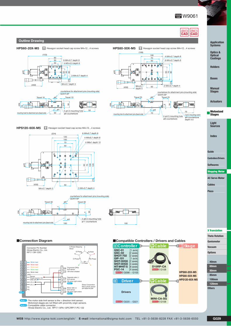
Outline Drawing
Hexagon socket head cap screw M4×12…4 screwsHPS60-20X-M5 Hexagon socket head cap screw M4×12…4 screwsHPS80-50X-M5
Hexagon socket head cap screw M4×12…4 screwsHPS120-60X-M5
4-φ4.5 mounting holeφ8 counterbore
6-M4×0.7 depth 8
4-M3×0.5 depth 6
M4×0.7 depth 5
counterbore for attachment pins (mounting side)GOHT-AP
mounting hole for attachment pins (bezel side)
(153)
605032
605032
(15)
30
15(29)
50
φ4
6.5
50
φ20
φ6
1
Travel 10 Travel 10
(450)
(199)
10070
8070(1
5)30
15(29)
70
φ4
6
70φ
20
φ6
1
Travel 25 Travel 25
(450)
50
50
50
4-φ4.5 mounting holeφ8 counterbore
4-M4×0.7 depth 8
M4×0.7depth 5
counterbore for attachment pins (mounting side)GOHT-AP
mounting hole for attachment pins (bezel side)
6-M4×0.7 depth 8
4-φ4.5 mounting notchφ8 counterbore depth 4.5
2-M4×0.7 depth 4
(224)
120
50
120
50
(15)
30
15
(29)
100
φ4
4
100
φ20
φ6
1
Travel 30 Travel 30
(450)
100
100
70
70
50
4-φ6.5 mounting holeφ11 counterbore
6-M4x0.7 depth 8
counterbore for attachment pins (mounting side)GOHT-AP
mounting hole for attachment pins (bezel side)
4-M6x1 depth 12
4-M4x0.7 depth 8
M4×0.7 depth 5 2-M4×0.7 depth 4
2-M4×0.7 depth 4
Stage
Driver
Drivers
Cable
ControllerGSC-01GSC-02SHOT-702GIP-101SHOT-302GSSHOT-304GSHIT-M・HIT-SPGC-14
[1 axis][2 axes][2 axes][1 axis][2 axes][4 axes][8 axes][4 axes]
D15RP-CA
Cable
MINI-CA-SGG020 − G021 G108
G098 − G105G108
HPS60-20X-M5HPS80-50X-M5HPS120-60X-M5
■Compatible Controllers / Drivers and Cables
Motor lead
Motor lead
Motor lead
Motor lead
Motor lead
SensorPower source 12VGND (0V)
LS (+)
LS (−)
ORG
FG
FG
B-PhaseD-Phase
A phase
C-Phase
E-Phase
5-Phase SteppingMotorConnector Pin Number
Hirose Electric Co., Ltd.RP17-13R-12SC
Sharp CorporationMicro photo sensorGP1S097HCZ0F
1
2
3
4
5
6
7
8
9
10
11
12
1
2
3
4
5
6
7
8
9
10
11
12
Originside (ORG)limit sensorON when shaded
■Connection Diagram
Opposite side (−)limit sensor
Motor side (+)limit sensor
ON when light enters
ON when light enters
Note 1
Note 1Note 2
The motor side limit sensor is the + direction limit sensor.Motorized stages are not fitted with proximity origin sensors.Compatible cable connector: Hirose Electric Co., Ltd. RP17-13PA-12PC/RP17-PC-122
Note 1
Note 2

G030
Mot ion Cont ro l Products
Guide
Controllers/Drivers
Softwares
AC Servo Motor
Cables
Piezo
X Translation
Theta Rotation
Goniometer
Vacuum
□40mm
□80mm
□85mm
□100mm
□120mm
Others
Application Systems
Optics & Optical Coatings
Holders
Bases
Manual Stages
Actuators
Motoeized Stages
Light Sources
Index
□60mm
Options
Stepping Motor
High Performance Motorized Stage Options HPS Option
Specifications (ex. HPS60-20X)Part Number HPS60-20X-M2 HPS60-20X-MA HPS60-20X-ML
MechanicalSpecifications
Travel [mm] 20 20 20
Table Size [mm] 60×60 60×60 60×60
Feed Screw Ball screw diameter φ6mm, 1mm lead
Ball screw diameter φ6mm, 1mm lead
Ball screw diameter φ6mm, 1mm lead
Positioning Slide Ball guide Ball guide Ball guide
Stage Material Aluminum Aluminum Aluminum
Finish Black anodized Black anodized Black anodized
Weight [kg] 0.6 1 0.6
AccuracySpecifications
Resolution (Full) [μm/pulse] 5 2 (500P/R) −(Half) [μm/pulse] 2.5 1 (1000P/R) −
MAX Speed [mm/sec] 20 40 −Positioning Accuracy [μm] 15 15 −Positional Repeatability [μm] ±2 ±0.5 −Load Capacity [N] 49 (5kgf) 49 (5kgf) 49 (5kgf)
Moment Stiffness
Pitch [″/N・cm] 0.4 0.4 0.4
Yaw [″/N・cm] 0.4 0.4 0.4
Roll [″/N・cm] 0.3 0.3 0.3
Lost Motion [μm] 1 1 −Backlash [μm] 1 1 1
Parallelism [μm] 30 30 30
Running Parallelism [μm] 10 10 10
Pitch [″] / Yaw [″] 25/25 25/25 25-25
Sensor
Sensor Part Number Micro photo sensor: GP1S097HCZ (Sharp Corporation)
Micro photo sensor: GP1S097HCZ (Sharp Corporation)
Micro photo sensor: GP1S097HCZ (Sharp Corporation)
Limit Sensor Equipped (NORMAL CLOSE) Equipped (NORMAL CLOSE) Equipped (NORMAL CLOSE)
Origin Sensor Equipped (NORMAL OPEN) Equipped (NORMAL OPEN) Equipped (NORMAL OPEN)
Proximity Origin Sensor None None None
Motor / Sensor Specifications
Motor
Type 2-phase stepping motor (Oriental Motor Co., Ltd.)
α STEP motor (Oriental Motor Co., Ltd.) (No motor)
Motor Part Number PKP223D15B (□28mm) ARM26SBK (□28mm) −Step Angle 1.8° 0.72°(500P/R) −
DriverPart Number A8576-0415Y ARD-K −Power input DC24V±10% 1A DC24V ±10% 0.9A −
Sensor
Power Voltage DC5 - 24V ±10%
Current Consumption 60mA or lower (20mA or lower per sensor) A8576-0415Y
Control Output DC24V±10% 1A
Output LogicNPN open collector output DC30V or lower, 50mA
When load current is 16mA, the residual voltage is under 0.4V When load current is 50mA, the residual voltage is under 0.7VIn the case of light shielded ,output transistor OFF (No conduction): Limit sensor
▶Please contact us when assembled into XYZ axis or use in reversion on the ceiling or vertical direction.
▶Replacement with electromagnetic brakes or grease change is also available. Contact our International Sales Division for more information.
Guide
Specification Method of Option Code
Stage size Travel Opposite Model Motor option
60 20 5None
HPS 80 - 50 X - M 2R
120 60 AL
2 Phase Motor with Driver
It can reduce the total cost because a driver is equipped. On the other hand, precision is inferior to 5 phase motors.
α Stepping Motor with Driver
Can be replaced with an α stepping motor with driver which can move fast. The motor also has built-in encoder.
No MotorNo Motor Provide a stage without motor because the customer mounts own motor. Note that mounting and adjustment of a motor requires specialized skills.
None: Standerd model R: Opposite model
5: 5 Phase Stepping Motor (Standerd model)2: 2 Phase Motor with DriverA: α-step Motor with DriverL: No motor
■Example of Code Specification
HPS60-20X□-M□■Option Code
HPS120-60X-MA
■Features of Options

G031WEB http://www.sigma-koki.com/english/ E-mail [email protected] TEL +81-3-5638-8228 FAX +81-3-5638-6550
Guide
Controllers/Drivers
Softwares
AC Servo Motor
Cables
Piezo
X Translation
Theta Rotation
Goniometer
Vacuum
□40mm
□80mm
□85mm
□100mm
□120mm
Others
Application Systems
Optics & Optical Coatings
Holders
Bases
Manual Stages
Actuators
Motoeized Stages
Light Sources
Index
□60mm
Options
Stepping Motor
Outline Drawing
Section 5 PhaseStepping Motor
2 PhaseStepping Motor αSTEP Motor
Positioning Accuracy ○ ○ ◎
Minute Feed Accuracy ○ ○ ○
Speed Stability ○ △ ◎
Heat Generation (Continuous Operation) ○ △ ◎
Max. Speed ○ ○ ◎
Rising Responsiveness ○ ○ ◎
■(Reference) Motor Comparison Table
Hexagon socket head cap screw M4×8…6 screws
HPS60-20X-M2
Hexagon socket head cap screw M4×8…6 screws
HPS60-20X-MA
Hexagon socket head cap screw M4×8…6 screws
HPS60-20X-ML (110)605032
605032
(15)
30(29)
50φ4
6.5
50
1
Travel 10Travel 10
φ22
H7
20.5 6
8.5
φ4
g6
10
23
23
7
4-φ4.5 mounting holeφ8 counterbore
6-M4×0.7 depth 8
4-M3×0.5 depth 6
counterbore for attachment pins (mounting side)GOHT-AP
mounting hole for attachment pins (bezel side)
4-φ3 drill holeφ5 counterbore depth 3 φ6
(450)
(153)605032
605032
(15)
30
15(2
9)
50
φ4
6.5
50
φ6
1
Travel 10 Travel 10
(450)
4-φ4.5 mounting holeφ8 counterbore
6-M4×0.7 depth 8
4-M3×0.5 depth 6
M4×0.7 depth 5
counterbore for attachment pins (mounting side)GOHT-AP
mounting hole for attachment pins (bezel side)
φ20
(187)605032
605032
(15)
30(29)
50
φ4
6.5
50
φ20
1
Travel 10 Travel 10
(450)
15
4-φ4.5 mounting holeφ8 counterbore
6-M4×0.7 depth 8
4-M3×0.5 depth 6
M4×0.7 depth 5
counterbore for attachment pins (mounting side)GOHT-AP
mounting hole for attachment pins (bezel side)
φ6
■Connection Diagram
SensorPower source 12VGND (0V)
LS (+)
LS (−)
ORG
NC
NC
NC
NC
Connector Pin NumberHirose Electric Co., Ltd.RP17-13JA-12SC
Sharp CorporationMicro photo sensorGP1S097HCZ0F
1
2
3
4
5
6
7
8
9
1
2
3
4
5
6
7
8
9Originside (ORG)limit sensorON when shaded
Opposite side (−)limit sensor
Motor side (+)limit sensor
ON when light enters
ON when light enters
Note 1
Note 1
The motor side limit sensor is the (+) forward direction limit sensor. There is no origin proximity sensor for this motorized stage.Compatible cable connector: Hirose Electric Co., Ltd. RP17-13PA-12PC/RP17-PC-122
Note 1
Note 2
Note 2 *Rough guide for when the motors are mounted on our motorized stage. (◎ : goodness ○ : standard △ : inferior)
G032
Mot ion Cont ro l Products
Guide
Controllers/Drivers
Softwares
AC Servo Motor
Cables
Piezo
Theta Rotation
Goniometer
Vacuum
Options
□40mm
□60mm
□80mm
□100mm
□120mm
Others
Application Systems
Optics & Optical Coatings
Holders
Bases
Manual Stages
Actuators
Motoeized Stages
Light Sources
Index
□85mm
X Translation
Stepping Motor
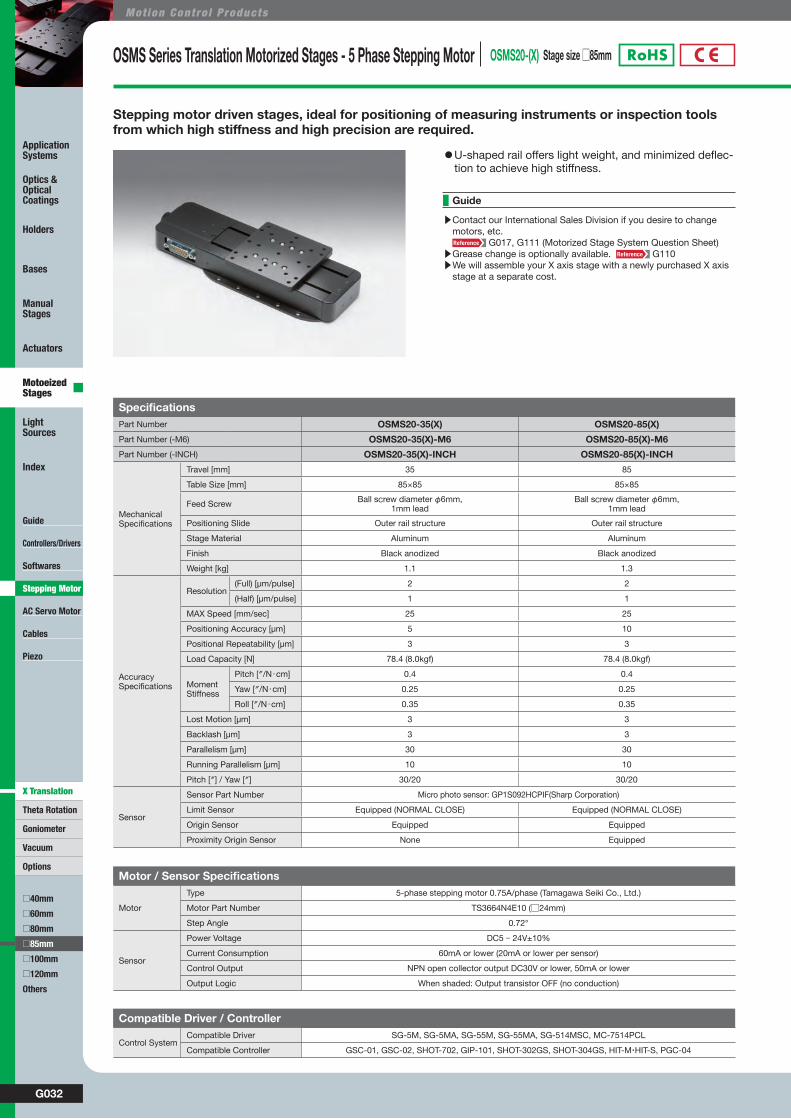
OSMS Series Translation Motorized Stages - 5 Phase Stepping Motor OSMS20-(X) Stage size □85mm
Stepping motor driven stages, ideal for positioning of measuring instruments or inspection tools from which high stiffness and high precision are required.
SpecificationsPart Number OSMS20-35(X) OSMS20-85(X)
Part Number (-M6) OSMS20-35(X)-M6 OSMS20-85(X)-M6
Part Number (-INCH) OSMS20-35(X)-INCH OSMS20-85(X)-INCH
MechanicalSpecifications
Travel [mm] 35 85
Table Size [mm] 85×85 85×85
Feed Screw Ball screw diameter φ6mm, 1mm lead
Ball screw diameter φ6mm, 1mm lead
Positioning Slide Outer rail structure Outer rail structure
Stage Material Aluminum Aluminum
Finish Black anodized Black anodized
Weight [kg] 1.1 1.3
AccuracySpecifications
Resolution (Full) [μm/pulse] 2 2
(Half) [μm/pulse] 1 1
MAX Speed [mm/sec] 25 25
Positioning Accuracy [μm] 5 10
Positional Repeatability [μm] 3 3
Load Capacity [N] 78.4 (8.0kgf) 78.4 (8.0kgf)
Moment Stiffness
Pitch [″/N・cm] 0.4 0.4
Yaw [″/N・cm] 0.25 0.25
Roll [″/N・cm] 0.35 0.35
Lost Motion [μm] 3 3
Backlash [μm] 3 3
Parallelism [μm] 30 30
Running Parallelism [μm] 10 10
Pitch [″] / Yaw [″] 30/20 30/20
Sensor
Sensor Part Number Micro photo sensor: GP1S092HCPIF(Sharp Corporation)
Limit Sensor Equipped (NORMAL CLOSE) Equipped (NORMAL CLOSE)
Origin Sensor Equipped Equipped
Proximity Origin Sensor None Equipped
Motor / Sensor Specifications
Motor
Type 5-phase stepping motor 0.75A/phase (Tamagawa Seiki Co., Ltd.)
Motor Part Number TS3664N4E10 (□24mm)
Step Angle 0.72°
Sensor
Power Voltage DC5 - 24V±10%
Current Consumption 60mA or lower (20mA or lower per sensor)
Control Output NPN open collector output DC30V or lower, 50mA or lower
Output Logic When shaded: Output transistor OFF (no conduction)
Compatible Driver / Controller
Control SystemCompatible Driver SG-5M, SG-5MA, SG-55M, SG-55MA, SG-514MSC, MC-7514PCL
Compatible Controller GSC-01, GSC-02, SHOT-702, GIP-101, SHOT-302GS, SHOT-304GS, HIT-M・HIT-S, PGC-04
▶Contact our International Sales Division if you desire to change motors, etc.
G017, G111 (Motorized Stage System Question Sheet)▶Grease change is optionally available. G110▶We will assemble your X axis stage with a newly purchased X axis
stage at a separate cost.
Guide
◦U-shaped rail offers light weight, and minimized deflec-tion to achieve high stiffness.
G033WEB http://www.sigma-koki.com/english/ E-mail [email protected] TEL +81-3-5638-8228 FAX +81-3-5638-6550
Guide
Controllers/Drivers
Softwares
AC Servo Motor
Cables
Piezo
Theta Rotation
Goniometer
Vacuum
Options
□40mm
□60mm
□80mm
□100mm
□120mm
Others
Application Systems
Optics & Optical Coatings
Holders
Bases
Manual Stages
Actuators
Motoeized Stages
Light Sources
Index
□85mm
X Translation
Stepping Motor
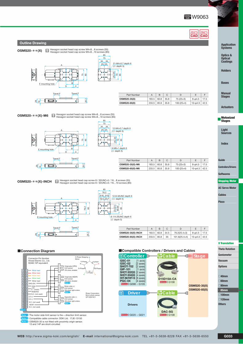
W9063CatalogCode
Outline Drawing
Hexagon socket head cap screw M4×8…8 screws (35)Hexagon socket head cap screw M4×8…10 screws (85)OSMS20-**(X)
Hexagon socket head cap screw M4×8…8 screws (35)Hexagon socket head cap screw M4×8…10 screws (85)OSMS20-**(X)-M6
Hexagon socket head cap screw 8 / 32UNC×5 / 16…8 screws (35)Hexagon socket head cap screw 8 / 32UNC×5 / 16…10 screws (85)OSMS20-**(X)-INCH
85
A
B75
D
29 35.7
Travel FTravel F
16
85
75
35 3525 25
8570
2525
CE mounting hole
☆ ☆ ☆ ☆ ☆
21-M4×0.7 depth 6(☆ depth 5)
8575 8585
2525
35
70
35
2525
75
A
B
CD
1629
Travel F Travel F
35.7
9-M6×1 depth 6(☆ depth 5)
12-M4×0.7 depth 6(☆ depth 5)
E mounting hole
85
85
25.4
25.425.434.93
69.8
5
34.93
25.4
76.2
8576.2
A
BCD
35.7
1629
Travel FTravel F
12-8-32UNC depth 6(☆ depth 5)
6-1/4-20UNC depth 6(☆ depth 5)
E mounting hole
Stage
Driver
Drivers
Cable
ControllerGSC-01GSC-02SHOT-702GIP-101SHOT-302GSSHOT-304GSHIT-M/HIT-SPGC-04
[1 axis][2 axes][2 axes][1 axis][2 axes][4 axes][8 axes][4 axes]
Cable
OSMS20-35(X)OSMS20-85(X)
■Compatible Controllers / Drivers and Cables
DAC-SG
D15D15A-CA
G098 − G105G108
G020 − G021 G108
■Connection Diagram
Motor lead
Motor lead
Motor lead
Motor lead
Motor lead
ORG+VS5 − 24VDCRESERVE
LS (+)
LS (−)
Connector Pin NumberHirose Electric Co., Ltd.SDAB-15P equivalent
Sharp CorporationMicro photo sensorGP1S097HC1
1
2
3
4
5
6
7
8
9
10
11
12
13
14
15
1
2
3
4
5
6
7
8
9
10
11
12
13
14
15 N.C. (not used)
N.C. (not used)
NEAR
GND (0V)
N.C. (not used)
A phase
B-Phase
C-Phase
D-Phase
E-Phase
5-Phase SteppingMotor
The motor side limit sensor is the + direction limit sensor.
OSMS20-35 is not fitted with proximity origin sensor. 13 and 14P are short-circuited
Compatible cable connector: DDK Ltd. 17JE-13150
Note 1
Note 2
Note 3
Note 2
Originside (NEAR)limit sensorON when shaded
Originside (ORG)limit sensorON when shaded
Motor side (+)limit sensorON when light entersNote 1
Opposite side (−)limit sensorON when light entersNote 1
Note 3
Part Number A B C D E F
OSMS20-35(X)-INCH 183.5 60.8 34.5 76.2(25.4×3) 8-φ4.5 17.5
OSMS20-85(X)-INCH 233.5 85.8 35 101.6(25.4×4) 10-φ4.5 42.5
Part Number A B C D E F
OSMS20-35(X)-M6 183.5 60.8 35.8 75 (25×3) 8-φ4.5 17.5
OSMS20-85(X)-M6 233.5 85.8 35.8 100 (25×4) 10-φ4.5 42.5
Part Number A B C D E F
OSMS20-35(X) 183.5 60.8 35.8 75 (25×3) 8-φ4.5 17.5
OSMS20-85(X) 233.5 85.8 35.8 100 (25×4) 10-φ4.5 42.5

G034
Mot ion Cont ro l Products
Guide
Controllers/Drivers
Softwares
AC Servo Motor
Cables
Piezo
Theta Rotation
Goniometer
Vacuum
Options
□40mm
□60mm
□80mm
□100mm
□120mm
Others
Application Systems
Optics & Optical Coatings
Holders
Bases
Manual Stages
Actuators
Motoeized Stages
Light Sources
Index
□85mm
X Translation
Stepping Motor
OSMS Series Translation Motorized Stages - 5 Phase Stepping Motor OSMS20-(XY) Stage size □85mm
SpecificationsPart Number OSMS20-35(XY) OSMS20-85(XY)Part Number (-M6) OSMS20-35(XY)-M6 OSMS20-85(XY)-M6Part Number (-INCH) OSMS20-35(XY)-INCH OSMS20-85(XY)-INCH
MechanicalSpecifications
Travel [mm] 35 85
Table Size [mm] 85×85 85×85
Feed Screw Ball screw diameter φ6mm, 1mm lead Ball screw diameter φ6mm, 1mm lead
Positioning Slide Outer rail structure Outer rail structure
Stage Material Aluminum Aluminum
Finish Black anodized Black anodized
Weight [kg] 2.2 2.6
AccuracySpecifications
Resolution (Full) [μm/pulse] 2 2
(Half) [μm/pulse] 1 1
MAX Speed [mm/sec] 25 25
Load Capacity [N] 68.6(7.0kgf) 68.6(7.0kgf)
Backlash [μm] 3 3
Orthogonality of Motion [μm] 5 5
Sensor
Sensor Part Number Micro photo sensor: GP1S092HCPIF(Sharp Corporation)
Limit Sensor Equipped (NORMAL CLOSE) Equipped (NORMAL CLOSE)
Origin Sensor Equipped Equipped
Proximity Origin Sensor None Equipped
(Reference) Precision Specifications of Single Axis StagePart Number OSMS20-35(X) OSMS20-85(X)
AccuracySpecifications
Positioning Accuracy [μm] 5 7
Positional Repeatability [μm] 3 3
Moment Stiffness
Pitch [″/N・cm] 0.4 0.4
Yaw [″/N・cm] 0.25 0.25
Roll [″/N・cm] 0.35 0.35
Lost Motion [μm] 3 3
Parallelism [μm] 30 30
Running Parallelism [μm] 10 10
Motor / Sensor Specifications
Motor
Type 5-phase stepping motor 0.75A/phase (Tamagawa Seiki Co., Ltd.)
Motor Part Number TS3664N4E10 (□24mm)
Step Angle 0.72°
Sensor
Power Voltage DC5 - 24V±10%
Current Consumption 60mA or lower (20mA or lower per sensor)
Control Output NPN open collector output DC30V or lower, 50mA or lower
Output Logic When shaded: Output transistor OFF (no conduction)
Compatible Driver / Controller
Control SystemCompatible Driver SG-5M, SG-5MA, SG-55M, SG-55MA, SG-514MSC, MC-7514PCL
Compatible Controller GSC-01, GSC-02, SHOT-702, GIP-101, SHOT-302GS, SHOT-304GS, HIT-M・HIT-S, PGC-04
Stepping motor driven stages, ideal for positioning of measuring instruments or inspection tools from which high stiffness and high precision are required.
▶Contact our International Sales Division if you desire to change motors, etc.
G017, G111 (Motorized Stage System Question Sheet)▶Grease change is optionally available. G110▶We will assemble your X axis stage with a newly purchased X axis
stage at a separate cost.
Guide
◦U-shaped rail offers light weight, and minimized deflec-tion to achieve high stiffness.

G035WEB http://www.sigma-koki.com/english/ E-mail [email protected] TEL +81-3-5638-8228 FAX +81-3-5638-6550
Guide
Controllers/Drivers
Softwares
AC Servo Motor
Cables
Piezo
Theta Rotation
Goniometer
Vacuum
Options
□40mm
□60mm
□80mm
□100mm
□120mm
Others
Application Systems
Optics & Optical Coatings
Holders
Bases
Manual Stages
Actuators
Motoeized Stages
Light Sources
Index
□85mm
X Translation
Stepping Motor
W9064CatalogCode
Outline Drawing
■Connection Diagram
Motor lead
Motor lead
Motor lead
Motor lead
Motor lead
ORG+VS5 − 24VDCRESERVE
LS (+)
LS (−)
Connector Pin NumberHirose Electric Co., Ltd.SDAB-15P equivalent
Sharp CorporationMicro photo sensorGP1S097HC1
1
2
3
4
5
6
7
8
9
10
11
12
13
14
15
1
2
3
4
5
6
7
8
9
10
11
12
13
14
15 N.C. (not used)
N.C. (not used)
NEAR
GND (0V)
N.C. (not used)
A phase
B-Phase
C-Phase
D-Phase
E-Phase
5-Phase SteppingMotor
The motor side limit sensor is the + direction limit sensor.
OSMS20-35 is not fitted with proximity origin sensor. 13 and 14P are short-circuited
Compatible cable connector: DDK Ltd. 17JE-13150
Note 1
Note 2
Note 3
Note 2
Originside (NEAR)limit sensorON when shaded
Originside (ORG)limit sensorON when shaded
Motor side (+)limit sensorON when light entersNote 1
Opposite side (−)limit sensorON when light entersNote 1
Note 3
Stage
Driver
Drivers
Cable
ControllerGSC-01GSC-02SHOT-702GIP-101SHOT-302GSSHOT-304GSHIT-M/HIT-SPGC-04
[1 axis][2 axes][2 axes][1 axis][2 axes][4 axes][8 axes][4 axes]
Cable
OSMS20-35(XY)OSMS20-85(XY)
■Compatible Controllers / Drivers and Cables
DAC-SG
D15D15A-CA
G098 − G105G108
G020 − G021 G108
Hexagon socket head cap screw M3×6…4 screwsOSMS20-**(XY)
Hexagon socket head cap screw M3×6…4 screwsOSMS20-**(XY)-M6
Hexagon socket head cap screw M3×6…4 screwsOSMS20-**(XY)-INCH
85
75
67.2
85
B
85
AB
A
71.4
35.7
CD
Trav
el F
Trav
el F
Travel F Travel F
85
85
25
2525
35
70
35
25
75 E mounting hole
☆☆ ☆ ☆☆
21-M4×0.7 depth 6(☆ depth 5)
85
85
75
2525
70
35 35
25 25
AB
85
85
B
A
85
75
67.2
35.7
71.4
CD
Travel F Travel F
Trav
el F
Trav
el F
9-M6×1 depth 6(☆ depth 5)
12-M4×0.7 depth 6(☆ depth 5)
E mounting hole
AB
85
76.2
67.2
A
B
35.7
71.4
CD
85
85
76.2
69.8
525.4
25.4
34.93 34.93
25.4 25.4
Travel F 85 Travel F
Trav
el F
85 Tr
avel
F12-8-32UNC depth 6(☆depth 5)
6-1/4-20UNC depth 6(☆ depth 5)
E mounting hole
Part Number A B C D E F
OSMS20-35(XY)-INCH 183.5 60.8 34.5 76.2(25.4×3) 8-φ4.5 17.5
OSMS20-85(XY)-INCH 233.5 85.8 35 101.6(25.4×4) 10-φ4.5 42.5
Part Number A B C D E F
OSMS20-35(XY)-M6 183.5 60.8 35.8 75 (25×3) 8-φ4.5 17.5
OSMS20-85(XY)-M6 233.5 85.8 35.8 100 (25×4) 10-φ4.5 42.5
Part Number A B C D E F
OSMS20-35(XY) 183.5 60.8 35.8 75 (25×3) 8-φ4.5 17.5
OSMS20-85(XY) 233.5 85.8 35.8 100 (25×4) 10-φ4.5 42.5
G036
Mot ion Cont ro l Products
Guide
Controllers/Drivers
Softwares
AC Servo Motor
Cables
Piezo
Theta Rotation
Goniometer
Vacuum
Options
□40mm
□60mm
□80mm
□100mm
□120mm
Others
Application Systems
Optics & Optical Coatings
Holders
Bases
Manual Stages
Actuators
Motoeized Stages
Light Sources
Index
□85mm
X Translation
Stepping Motor
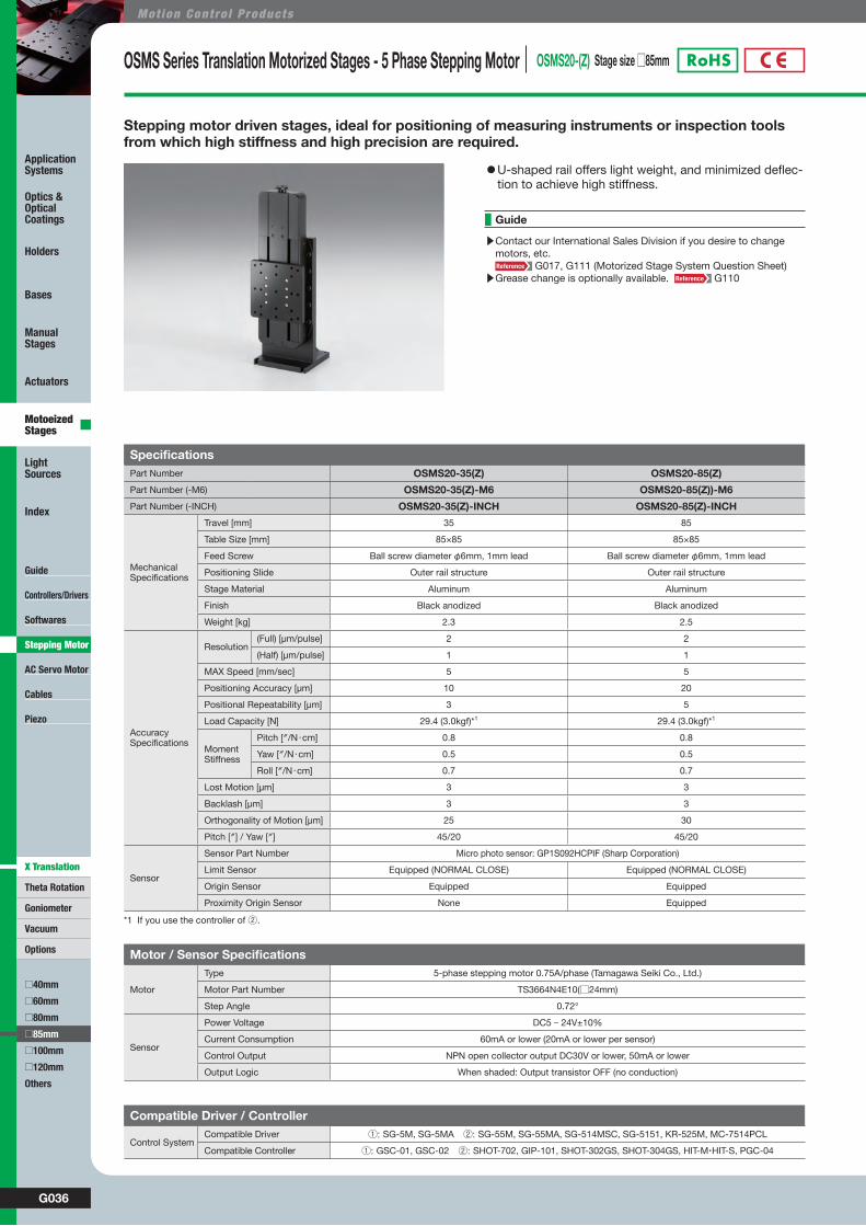
OSMS Series Translation Motorized Stages - 5 Phase Stepping Motor OSMS20-(Z) Stage size □85mm
SpecificationsPart Number OSMS20-35(Z) OSMS20-85(Z)
Part Number (-M6) OSMS20-35(Z)-M6 OSMS20-85(Z))-M6
Part Number (-INCH) OSMS20-35(Z)-INCH OSMS20-85(Z)-INCH
MechanicalSpecifications
Travel [mm] 35 85
Table Size [mm] 85×85 85×85
Feed Screw Ball screw diameter φ6mm, 1mm lead Ball screw diameter φ6mm, 1mm lead
Positioning Slide Outer rail structure Outer rail structure
Stage Material Aluminum Aluminum
Finish Black anodized Black anodized
Weight [kg] 2.3 2.5
AccuracySpecifications
Resolution (Full) [μm/pulse] 2 2
(Half) [μm/pulse] 1 1
MAX Speed [mm/sec] 5 5
Positioning Accuracy [μm] 10 20
Positional Repeatability [μm] 3 5
Load Capacity [N] 29.4 (3.0kgf)*1 29.4 (3.0kgf)*1
Moment Stiffness
Pitch [″/N・cm] 0.8 0.8
Yaw [″/N・cm] 0.5 0.5
Roll [″/N・cm] 0.7 0.7
Lost Motion [μm] 3 3
Backlash [μm] 3 3
Orthogonality of Motion [μm] 25 30
Pitch [″] / Yaw [″] 45/20 45/20
Sensor
Sensor Part Number Micro photo sensor: GP1S092HCPIF (Sharp Corporation)
Limit Sensor Equipped (NORMAL CLOSE) Equipped (NORMAL CLOSE)
Origin Sensor Equipped Equipped
Proximity Origin Sensor None Equipped
Motor / Sensor Specifications
Motor
Type 5-phase stepping motor 0.75A/phase (Tamagawa Seiki Co., Ltd.)
Motor Part Number TS3664N4E10(□24mm)
Step Angle 0.72°
Sensor
Power Voltage DC5 - 24V±10%
Current Consumption 60mA or lower (20mA or lower per sensor)
Control Output NPN open collector output DC30V or lower, 50mA or lower
Output Logic When shaded: Output transistor OFF (no conduction)
Compatible Driver / Controller
Control SystemCompatible Driver ①: SG-5M, SG-5MA ②: SG-55M, SG-55MA, SG-514MSC, SG-5151, KR-525M, MC-7514PCL
Compatible Controller ①: GSC-01, GSC-02 ②: SHOT-702, GIP-101, SHOT-302GS, SHOT-304GS, HIT-M・HIT-S, PGC-04
Stepping motor driven stages, ideal for positioning of measuring instruments or inspection tools from which high stiffness and high precision are required.
▶Contact our International Sales Division if you desire to change motors, etc.
G017, G111 (Motorized Stage System Question Sheet)▶Grease change is optionally available. G110
Guide
◦U-shaped rail offers light weight, and minimized deflec-tion to achieve high stiffness.
*1 If you use the controller of ②.
G037WEB http://www.sigma-koki.com/english/ E-mail [email protected] TEL +81-3-5638-8228 FAX +81-3-5638-6550
Guide
Controllers/Drivers
Softwares
AC Servo Motor
Cables
Piezo
Theta Rotation
Goniometer
Vacuum
Options
□40mm
□60mm
□80mm
□100mm
□120mm
Others
Application Systems
Optics & Optical Coatings
Holders
Bases
Manual Stages
Actuators
Motoeized Stages
Light Sources
Index
□85mm
X Translation
Stepping Motor
W9065CatalogCode
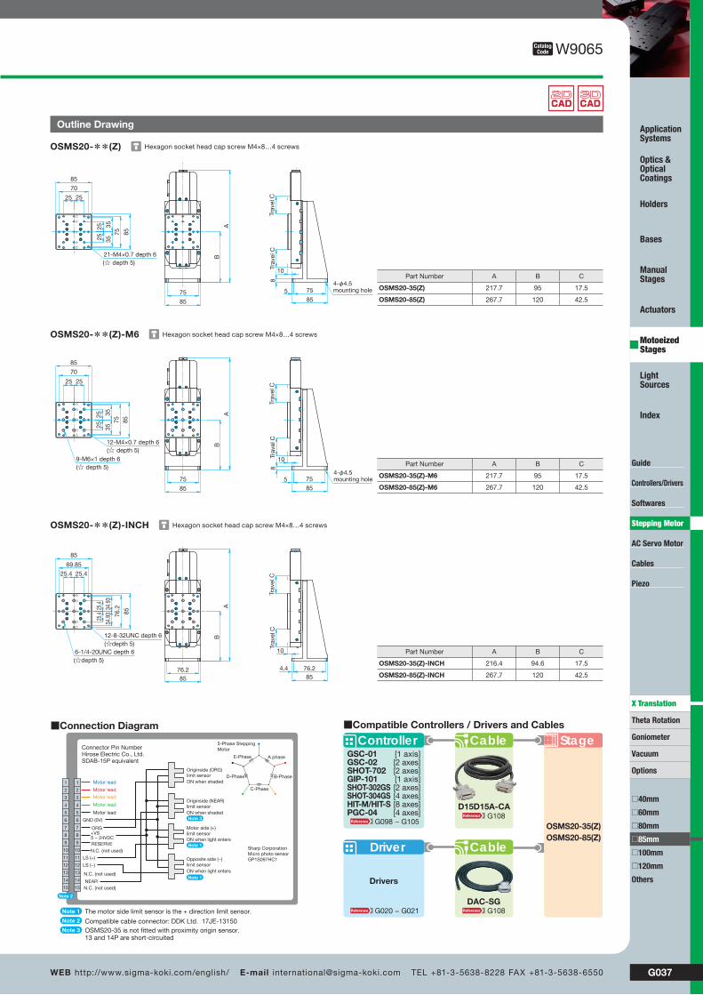
Outline Drawing
Stage
Driver
Drivers
Cable
ControllerGSC-01GSC-02SHOT-702GIP-101SHOT-302GSSHOT-304GSHIT-M/HIT-SPGC-04
[1 axis][2 axes][2 axes][1 axis][2 axes][4 axes][8 axes][4 axes]
Cable
OSMS20-35(Z)OSMS20-85(Z)
■Compatible Controllers / Drivers and Cables
DAC-SG
D15D15A-CA
G098 − G105G108
G020 − G021 G108
Hexagon socket head cap screw M4×8…4 screwsOSMS20-**(Z)
Hexagon socket head cap screw M4×8…4 screwsOSMS20-**(Z)-M6
Hexagon socket head cap screw M4×8…4 screwsOSMS20-**(Z)-INCH
85
85
25
2525
35
70
35
25
75
10
B
Tra
vel C
Tra
vel C
5 75
8575
85
8
A
21-M4×0.7 depth 6(☆ depth 5)
4-φ4.5 mounting hole
85
85
75
25 25
70
3535
2525
A
B
75
85
5 75
85
Tra
vel C
Tra
vel C
8
109-M6×1 depth 6(☆ depth 5)
12-M4×0.7 depth 6(☆ depth 5)
4-φ4.5 mounting hole
85
85
76.2
69.85
25.425.4
34.9
334
.93
25.4
25.4
76.24.485
Tra
vel C
Tra
vel C
10
76.285
B
A
12-8-32UNC depth 6(☆depth 5)
6-1/4-20UNC depth 6(☆depth 5)
■Connection Diagram
Motor lead
Motor lead
Motor lead
Motor lead
Motor lead
ORG+VS5 − 24VDCRESERVE
LS (+)
LS (−)
Connector Pin NumberHirose Electric Co., Ltd.SDAB-15P equivalent
Sharp CorporationMicro photo sensorGP1S097HC1
1
2
3
4
5
6
7
8
9
10
11
12
13
14
15
1
2
3
4
5
6
7
8
9
10
11
12
13
14
15 N.C. (not used)
N.C. (not used)
NEAR
GND (0V)
N.C. (not used)
A phase
B-Phase
C-Phase
D-Phase
E-Phase
5-Phase SteppingMotor
The motor side limit sensor is the + direction limit sensor.
OSMS20-35 is not fitted with proximity origin sensor. 13 and 14P are short-circuited
Compatible cable connector: DDK Ltd. 17JE-13150
Note 1
Note 2
Note 3
Note 2
Originside (NEAR)limit sensorON when shaded
Originside (ORG)limit sensorON when shaded
Motor side (+)limit sensorON when light entersNote 1
Opposite side (−)limit sensorON when light entersNote 1
Note 3
Part Number A B C
OSMS20-35(Z)-INCH 216.4 94.6 17.5
OSMS20-85(Z)-INCH 267.7 120 42.5
Part Number A B C
OSMS20-35(Z)-M6 217.7 95 17.5
OSMS20-85(Z)-M6 267.7 120 42.5
Part Number A B C
OSMS20-35(Z) 217.7 95 17.5
OSMS20-85(Z) 267.7 120 42.5
G038
Mot ion Cont ro l Products
Guide
Controllers/Drivers
Softwares
AC Servo Motor
Cables
Piezo
Theta Rotation
Goniometer
Vacuum
Options
□40mm
□60mm
□80mm
□100mm
□120mm
Others
Application Systems
Optics & Optical Coatings
Holders
Bases
Manual Stages
Actuators
Motoeized Stages
Light Sources
Index
□85mm
X Translation
Stepping Motor
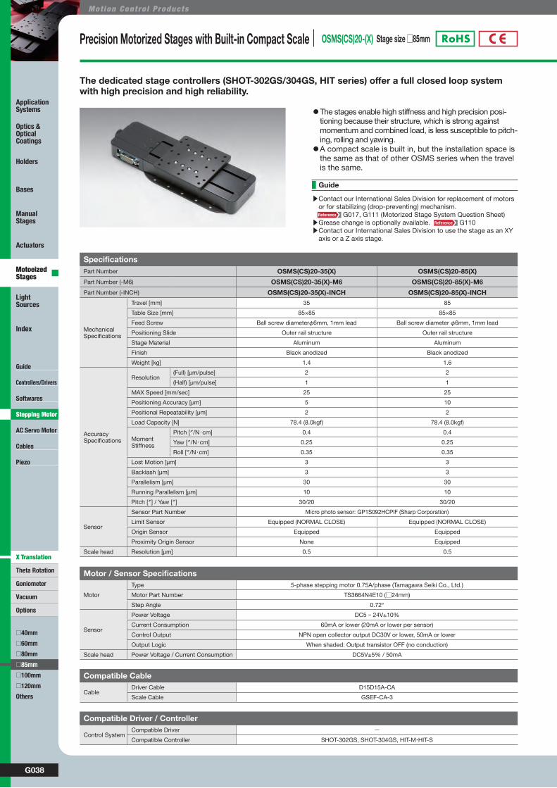
Precision Motorized Stages with Built-in Compact Scale OSMS(CS)20-(X) Stage size □85mm
The dedicated stage controllers (SHOT-302GS/304GS, HIT series) offer a full closed loop system with high precision and high reliability.
SpecificationsPart Number OSMS(CS)20-35(X) OSMS(CS)20-85(X)
Part Number (-M6) OSMS(CS)20-35(X)-M6 OSMS(CS)20-85(X)-M6
Part Number (-INCH) OSMS(CS)20-35(X)-INCH OSMS(CS)20-85(X)-INCH
MechanicalSpecifications
Travel [mm] 35 85
Table Size [mm] 85×85 85×85
Feed Screw Ball screw diameterφ6mm, 1mm lead Ball screw diameter φ6mm, 1mm lead
Positioning Slide Outer rail structure Outer rail structure
Stage Material Aluminum Aluminum
Finish Black anodized Black anodized
Weight [kg] 1.4 1.6
AccuracySpecifications
Resolution (Full) [μm/pulse] 2 2
(Half) [μm/pulse] 1 1
MAX Speed [mm/sec] 25 25
Positioning Accuracy [μm] 5 10
Positional Repeatability [μm] 2 2
Load Capacity [N] 78.4 (8.0kgf) 78.4 (8.0kgf)
Moment Stiffness
Pitch [″/N・cm] 0.4 0.4
Yaw [″/N・cm] 0.25 0.25
Roll [″/N・cm] 0.35 0.35
Lost Motion [μm] 3 3
Backlash [μm] 3 3
Parallelism [μm] 30 30
Running Parallelism [μm] 10 10
Pitch [″] / Yaw [″] 30/20 30/20
Sensor
Sensor Part Number Micro photo sensor: GP1S092HCPIF (Sharp Corporation)
Limit Sensor Equipped (NORMAL CLOSE) Equipped (NORMAL CLOSE)
Origin Sensor Equipped Equipped
Proximity Origin Sensor None Equipped
Scale head Resolution [μm] 0.5 0.5
Motor / Sensor Specifications
Motor
Type 5-phase stepping motor 0.75A/phase (Tamagawa Seiki Co., Ltd.)
Motor Part Number TS3664N4E10 (□24mm)
Step Angle 0.72°
Sensor
Power Voltage DC5 - 24V±10%
Current Consumption 60mA or lower (20mA or lower per sensor)
Control Output NPN open collector output DC30V or lower, 50mA or lower
Output Logic When shaded: Output transistor OFF (no conduction)
Scale head Power Voltage / Current Consumption DC5V±5% / 50mA
Compatible Driver / Controller
Control SystemCompatible Driver −Compatible Controller SHOT-302GS, SHOT-304GS, HIT-M・HIT-S
Compatible Cable
CableDriver Cable D15D15A-CA
Scale Cable GSEF-CA-3
▶Contact our International Sales Division for replacement of motors or for stabilizing (drop-preventing) mechanism.
G017, G111 (Motorized Stage System Question Sheet)▶Grease change is optionally available. G110▶Contact our International Sales Division to use the stage as an XY
axis or a Z axis stage.
Guide
◦The stages enable high stiffness and high precision posi-tioning because their structure, which is strong against momentum and combined load, is less susceptible to pitch-ing, rolling and yawing.
◦A compact scale is built in, but the installation space is the same as that of other OSMS series when the travel is the same.
G039WEB http://www.sigma-koki.com/english/ E-mail [email protected] TEL +81-3-5638-8228 FAX +81-3-5638-6550
Guide
Controllers/Drivers
Softwares
AC Servo Motor
Cables
Piezo
Theta Rotation
Goniometer
Vacuum
Options
□40mm
□60mm
□80mm
□100mm
□120mm
Others
Application Systems
Optics & Optical Coatings
Holders
Bases
Manual Stages
Actuators
Motoeized Stages
Light Sources
Index
□85mm
X Translation
Stepping Motor
W9066CatalogCode
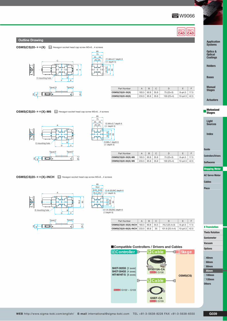
Outline Drawing
Hexagon socket head cap screw M3×6…4 screwsOSMS(CS)20-**(X)
Hexagon socket head cap screw M3×6…4 screwsOSMS(CS)20-**(X)-M6
Hexagon socket head cap screw M3×6…4 screwsOSMS(CS)20-**(X)-INCH
A
C
DB
F
29 35.7
Travel GTravel G
16
85
75
35 3525 25
8570
2525
EH mounting hole
☆ ☆ ☆ ☆ ☆
21-M4×0.7 depth 6(☆ depth 5)
85
85
2525
35
70
35
2525
75
A
B
CD
1629
Travel F Travel F
35.7
9-M6×1 depth 6(☆ depth 5)
12-M4×0.7 depth 6(☆ depth 5)
E mounting hole
85
85
25.4
25.425.434.93
69.8
5
34.93
25.4
76.2
8576.2
A
BCD
35.7
1629
Travel FTravel F
12-8-32UNC depth 6(☆ depth 5)
6-1/4-20UNC depth 6(☆depth 5)
E mounting hole
Part Number A B C D E F
OSMS(CS)20-35(X)-INCH 183.5 60.8 34.5 76.2 (25.4×3) 8-φ4.5 17.5
OSMS(CS)20-85(X)-INCH 233.5 85.8 35 101.6 (25.4×4) 10-φ4.5 42.5
Part Number A B C D E F
OSMS(CS)20-35(X)-M6 183.5 60.8 35.8 75 (25×3) 8-φ4.5 17.5
OSMS(CS)20-85(X)-M6 233.5 85.8 35.8 100 (25×4) 10-φ4.5 42.5
Part Number A B C D E F
OSMS(CS)20-35(X) 183.5 60.8 35.8 75 (25×3) 8-φ4.5 17.5
OSMS(CS)20-85(X) 233.5 85.8 35.8 100 (25×4) 10-φ4.5 42.5
GSEF-CA
D15D15A-CA
Stage
Cable
Controller
SHOT-302GSSHOT-304GSHIT-M/HIT-S
[2 axes][4 axes][8 axes]
Cable
OSMS(CS)
■Compatible Controllers / Drivers and Cables
G108
G109
G102 − G103

G040
Mot ion Cont ro l Products
Guide
Controllers/Drivers
Softwares
AC Servo Motor
Cables
Piezo
Theta Rotation
Goniometer
Vacuum
Options
□40mm
□60mm
□80mm
□85mm
Others
Application Systems
Optics & Optical Coatings
Holders
Bases
Manual Stages
Actuators
Motoeized Stages
Light Sources
Index
□120mm
□100mm
X Translation
Stepping Motor
OSMS Series Translation Motorized Stages - 5 Phase Stepping Motor OSMS26-(X) Stage size □100mm
SpecificationsPart Number OSMS26-50(X) OSMS26-100(X) OSMS26-200(X) OSMS26-300(X)
Part Number (-M6) OSMS26-50(X)-M6 OSMS26-100(X)-M6 OSMS26-200(X)-M6 OSMS26-300(X)-M6
Part Number (-INCH) OSMS26-50(X)-INCH OSMS26-100(X)-INCH OSMS26-200(X)-INCH OSMS26-300(X)-INCH
MechanicalSpecifications
Travel [mm] 50 100 200 300
Table Size [mm](M6, INCH)
100×100(120×120)
100×100(120×120)
100×100(120×120)
100×100(120×120)
Feed Screw Ball screw diameter φ8mm, 2mm lead
Ball screw diameter φ8mm, 2mm lead
Ball screw diameter φ8mm, 2mm lead
Ball screw diameter φ8mm, 2mm lead
Positioning Slide Outer rail structure Outer rail structure Outer rail structure Outer rail structure
Stage Material Aluminum Aluminum Aluminum Aluminum
Finish Black anodized Black anodized Black anodized Black anodized
Weight [kg] 2.2 2.7 3.8 4.0
AccuracySpecifications
Resolution (Full) [μm/pulse] 4 4 4 4
(Half) [μm/pulse] 2 2 2 2
MAX Speed [mm/sec] 40 40 40 40
Positioning Accuracy [μm] 5 10 15 20
Positional Repeatability [μm] 3 3 6 6
Load Capacity [N] 117 (12.0kgf) 117 (12.0kgf) 117 (12.0kgf) 117 (12.0kgf)
Moment Stiffness
Pitch [″/N・cm] 0.23 0.23 0.23 0.23
Yaw [″/N・cm] 0.12 0.12 0.12 0.12
Roll [″/N・cm] 0.2 0.2 0.2 0.2
Lost Motion [μm] 3 3 5 5
Backlash [μm] 3 3 3 3
Parallelism [μm] 50 50 50 50
Running Parallelism [μm] 10 10 10 20
Pitch [″] / Yaw [″] 25/20 25/20 30/25 30/25
Sensor
Sensor Part Number Micro photo sensor: GP1S092HCPIF (Sharp Corporation)
Limit Sensor Equipped(NORMAL CLOSE)
Equipped(NORMAL CLOSE)
Equipped (NORMAL CLOSE)
Equipped(NORMAL CLOSE)
Origin Sensor Equipped Equipped Equipped Equipped
Proximity Origin Sensor Equipped Equipped Equipped Equipped
Motor / Sensor Specifications
Motor
Type 5-phase stepping motor 0.75A/phase (Oriental Motor Co., Ltd.)
Motor Part Number PK525HPB-C4(□28mm)
Step Angle 0.72°
Sensor
Power Voltage DC5 - 24V±10%
Current Consumption 80mA or lower (20mA or lower per sensor)
Control Output NPN open collector output DC30V or lower, 50mA or lower
Output Logic When shaded: Output transistor OFF (no conduction)
Compatible Driver / Controller
Control SystemCompatible Driver SG-5M, SG-5MA, SG-55M, SG-55MA, SG-514MSC, MC-7514PCL
Compatible Controller GSC-01, GSC-02, SHOT-702, GIP-101, SHOT-302GS, SHOT-304GS, HIT-M・HIT-S, PGC-04
Stepping motor driven stages, ideal for positioning of measuring instruments or inspection tools from which high stiffness and high precision are required.
▶Contact our International Sales Division if you desire to change motors, etc.
G017, G111 (Motorized Stage System Question Sheet)▶Grease change is optionally available. G110▶We will assemble your X axis stage with a newly purchased X axis
stage at a separate cost.
Guide
◦U-shaped rail offers light weight, and minimized deflec-tion to achieve high stiffness.
G041WEB http://www.sigma-koki.com/english/ E-mail [email protected] TEL +81-3-5638-8228 FAX +81-3-5638-6550
Guide
Controllers/Drivers
Softwares
AC Servo Motor
Cables
Piezo
Theta Rotation
Goniometer
Vacuum
Options
□40mm
□60mm
□80mm
□85mm
□100mm
□120mm
Others
Application Systems
Optics & Optical Coatings
Holders
Bases
Manual Stages
Actuators
Motoeized Stages
Light Sources
Index
X Translation
Stepping Motor
□100mm
□120mm
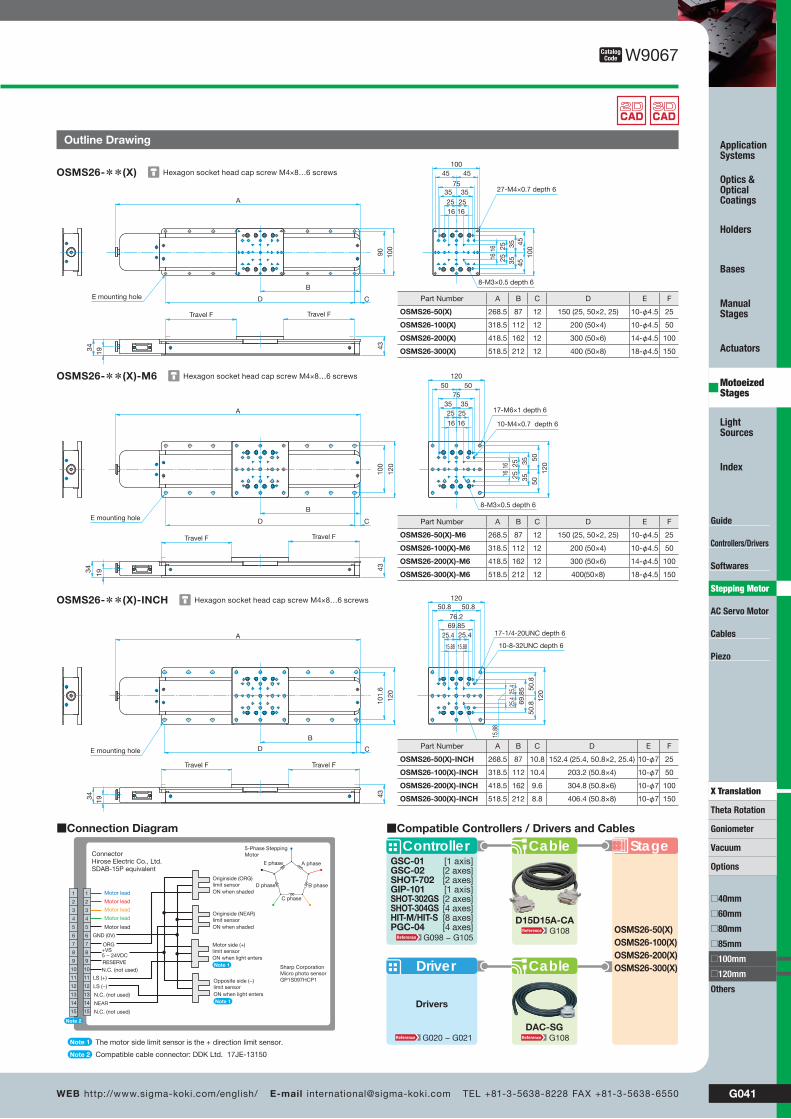
Hexagon socket head cap screw M4×8…6 screwsOSMS26-**(X)
Hexagon socket head cap screw M4×8…6 screwsOSMS26-**(X)-M6
Hexagon socket head cap screw M4×8…6 screwsOSMS26-**(X)-INCH
A
D
B
1934
Travel F Travel F
43
10045 45
35 3525 2516 16
100
454535
35252516
16
C
90 100
E mounting hole
27-M4×0.7 depth 6
8-M3×0.5 depth 6
75
120
120
50 50
35 3525 25
1616
5050
2525
3535
1616
A
120
100
CD
B
43
1934
Travel FTravel F
8-M3×0.5 depth 6
10-M4×0.7 depth 6
17-M6×1 depth 6
E mounting hole
75
120
120
15.88 15.88
15.8
8
25.425.4
69.8
5
69.85
25.4
25.4
76.2
50.8
50.8
50.8
50.8
A
B
CD
101.
6
120
1934
Travel FTravel F
43
10-8-32UNC depth 6
17-1/4-20UNC depth 6
8-6-32UNC depth 6E mounting hole
W9067CatalogCode
Outline Drawing
Part Number A B C D E F
OSMS26-50(X) 268.5 87 12 150 (25, 50×2, 25) 10-φ4.5 25
OSMS26-100(X) 318.5 112 12 200 (50×4) 10-φ4.5 50
OSMS26-200(X) 418.5 162 12 300 (50×6) 14-φ4.5 100
OSMS26-300(X) 518.5 212 12 400 (50×8) 18-φ4.5 150
Part Number A B C D E F
OSMS26-50(X)-M6 268.5 87 12 150 (25, 50×2, 25) 10-φ4.5 25
OSMS26-100(X)-M6 318.5 112 12 200 (50×4) 10-φ4.5 50
OSMS26-200(X)-M6 418.5 162 12 300 (50×6) 14-φ4.5 100
OSMS26-300(X)-M6 518.5 212 12 400(50×8) 18-φ4.5 150
Part Number A B C D E F
OSMS26-50(X)-INCH 268.5 87 10.8 152.4 (25.4, 50.8×2, 25.4) 10-φ7 25
OSMS26-100(X)-INCH 318.5 112 10.4 203.2 (50.8×4) 10-φ7 50
OSMS26-200(X)-INCH 418.5 162 9.6 304.8 (50.8×6) 10-φ7 100
OSMS26-300(X)-INCH 518.5 212 8.8 406.4 (50.8×8) 10-φ7 150
Stage
Driver
Drivers
Cable
ControllerGSC-01GSC-02SHOT-702GIP-101SHOT-302GSSHOT-304GSHIT-M/HIT-SPGC-04
[1 axis][2 axes][2 axes][1 axis][2 axes][4 axes][8 axes][4 axes]
Cable
OSMS26-50(X)OSMS26-100(X)OSMS26-200(X)OSMS26-300(X)
■Compatible Controllers / Drivers and Cables
DAC-SG
D15D15A-CA
G108G020 − G021
G098 − G105G108
■Connection Diagram
Motor lead
Motor lead
Motor lead
Motor lead
Motor lead
ORG+VS5 − 24VDCRESERVE
LS (+)
LS (−)
Connector Hirose Electric Co., Ltd.SDAB-15P equivalent
Sharp CorporationMicro photo sensorGP1S097HCP1
1
2
3
4
5
6
7
8
9
10
11
12
13
14
15
1
2
3
4
5
6
7
8
9
10
11
12
13
14
15 N.C. (not used)
N.C. (not used)
NEAR
GND (0V)
N.C. (not used)
A phase
B phase
C phase
D phase
E phase
5-Phase SteppingMotor
Note 2
Note 1
Note 2
The motor side limit sensor is the + direction limit sensor.
Compatible cable connector: DDK Ltd. 17JE-13150
Originside (ORG)limit sensorON when shaded
Originside (NEAR)limit sensorON when shaded
Opposite side (−)limit sensorON when light entersNote 1
Motor side (+)limit sensorON when light entersNote 1

G042
Mot ion Cont ro l Products
Guide
Controllers/Drivers
Softwares
AC Servo Motor
Cables
Piezo
Theta Rotation
Goniometer
Vacuum
Options
□40mm
□60mm
□80mm
□85mm
Others
Application Systems
Optics & Optical Coatings
Holders
Bases
Manual Stages
Actuators
Motoeized Stages
Light Sources
Index
□120mm
□100mm
X Translation
Stepping Motor
OSMS Series Translation Motorized Stages - 5 Phase Stepping Motor OSMS26-(XY) Stage size □100mm
SpecificationsPart Number OSMS26-50(XY) OSMS26-100(XY) OSMS26-200(XY) OSMS26-300(XY)Part Number (-M6) OSMS26-50(XY)-M6 OSMS26-100(XY)-M6 OSMS26-200(XY)-M6 OSMS26-300(XY)-M6Part Number (-INCH) OSMS26-50(XY)-INCH OSMS26-100(XY)-INCH OSMS26-200(XY)-INCH OSMS26-300(XY)-INCH
MechanicalSpecifications
Travel [mm] 50 100 200 300
Table Size [mm](M6, INCH)
100×100(120×120)
100×100(120×120)
100×100(120×120)
100×100(120×120)
Feed Screw Ball screw diameter φ8mm, 2mm lead
Ball screw diameter φ8mm, 2mm lead
Ball screw diameter φ8mm, 2mm lead
Ball screw diameter φ8mm, 2mm lead
Positioning Slide Outer rail structure Outer rail structure Outer rail structure Outer rail structure
Stage Material Aluminum Aluminum Aluminum Aluminum
Finish Black anodized Black anodized Black anodized Black anodized
Weight [kg] 4.4 5.4 7.6 8.0
AccuracySpecifications
Resolution (Full) [μm/pulse] 4 4 4 4
(Half) [μm/pulse] 2 2 2 2
MAX Speed [mm/sec] 40 40 40 40
Load Capacity [N] 98 (10.0kgf) 98 (10.0kgf) 98 (10.0kgf) 98 (10.0kgf)
Backlash [μm] 3 3 3 3
Orthogonality of Motion [μm] 5 5 10 5
Sensor
Sensor Part Number Micro photo sensor: GP1S092HCPIF (Sharp Corporation)
Limit Sensor Equipped(NORMAL CLOSE)
Equipped(NORMAL CLOSE)
Equipped(NORMAL CLOSE)
Equipped(NORMAL CLOSE)
Origin Sensor Equipped Equipped Equipped Equipped
Proximity Origin Sensor Equipped Equipped Equipped Equipped
(Reference) Precision Specifications of Single Axis StagePart Number OSMS26-50(X) OSMS26-100(X) OSMS26-200(X) OSMS26-300(X)
AccuracySpecifications
Positioning Accuracy [μm] 5 10 15 15
Positional Repeatability [μm] 3 3 6 6
Moment Stiffness
Pitch [″/N・cm] 0.23 0.23 0.23 0.23
Yaw [″/N・cm] 0.12 0.12 0.12 0.12
Roll [″/N・cm] 0.2 0.2 0.2 0.2
Lost Motion [μm] 3 3 5 5
Parallelism [μm] 50 50 50 50
Running Parallelism [μm] 10 10 10 10
Motor / Sensor Specifications
Motor
Type 5-phase stepping motor 0.75A/phase (Oriental Motor Co., Ltd.)
Motor Part Number PK525HPB-C4 (□28mm)
Step Angle 0.72°
Sensor
Power Voltage DC5 - 24V±10%
Current Consumption 80mA or lower (20mA or lower per sensor)
Control Output NPN open collector output DC30V or lower, 50mA or lower
Output Logic When shaded: Output transistor OFF (no conduction)
Compatible Driver / Controller
Control SystemCompatible Driver SG-5M, SG-5MA, SG-55M, SG-55MA, SG-514MSC, MC-7514PCL
Compatible Controller GSC-01, GSC-02, SHOT-702, GIP-101, SHOT-302GS, SHOT-304GS, HIT-M・HIT-S, PGC-04
Stepping motor driven stages, ideal for positioning of measuring instruments or inspection tools from which high stiffness and high precision are required.
▶Contact our International Sales Division if you desire to change motors, etc.
G017, G111 (Motorized Stage System Question Sheet)▶Grease change is optionally available. G110▶We will assemble your X axis stage with a newly purchased X axis
stage at a separate cost.
Guide
◦U-shaped rail offers light weight, and minimized deflec-tion to achieve high stiffness.

G043WEB http://www.sigma-koki.com/english/ E-mail [email protected] TEL +81-3-5638-8228 FAX +81-3-5638-6550
Guide
Controllers/Drivers
Softwares
AC Servo Motor
Cables
Piezo
Theta Rotation
Goniometer
Vacuum
Options
□40mm
□60mm
□80mm
□85mm
Others
Application Systems
Optics & Optical Coatings
Holders
Bases
Manual Stages
Actuators
Motoeized Stages
Light Sources
Index
□120mm
□100mm
X Translation
Stepping Motor
W9068CatalogCode
Outline Drawing
Stage
Driver
Drivers
Cable
ControllerGSC-01GSC-02SHOT-702GIP-101SHOT-302GSSHOT-304GSHIT-M/HIT-SPGC-04
[1 axis][2 axes][2 axes][1 axis][2 axes][4 axes][8 axes][4 axes]
Cable
OSMS26-50(XY)OSMS26-100(XY)OSMS26-200(XY)OSMS26-300(XY)
■Compatible Controllers / Drivers and Cables
DAC-SG
D15D15A-CA
G108G020 − G021
G098 − G105G108
Hexagon socket head cap screw M4×8…6 screws
OSMS26-**(XY)
Hexagon socket head cap screw M4×8…6 screws
OSMS26-**(XY)-M6
Hexagon socket head cap screw M4×8…6 screws
OSMS26-**(XY)-INCH
1009079
BA
AB 86
43
CD
Trav
el F
Trav
el F
Travel F Travel F
100
100
2516
16
16
162525
35
35
35
35
25
45
45
45
45
E mounting hole
8-M3×0.5 depth 6
27-M4×0.7 depth 6
75
100
100
120
120
16
1616
162525
35
35
35
35
2525
75
50
50
50
50
CD
4386
AB
120
BA
120
12010079
Trav
el F
Trav
el F
Travel F Travel F
8-M3×0.5 depth 6
10-M4×0.7 depth 6
17-M6×1 depth 6
E mounting hole
120
120
76.269.85
69.8
550
.850
.8
25.42
5.415.8815.88
50.8 50.8
15.88 15.88
120101.6
79
AB
CD
4386A
B120Travel F Travel F
120
Trav
el F
Trav
el F
10-8-32UNC depth 6
17-1/4-20UNC depth 6
8-6-32UNC depth 6
E mounting hole
25.4 25.4
■Connection Diagram
Motor lead
Motor lead
Motor lead
Motor lead
Motor lead
ORG+VS5 − 24VDCRESERVE
LS (+)
LS (−)
Connector Hirose Electric Co., Ltd.SDAB-15P equivalent
Sharp CorporationMicro photo sensorGP1S097HCP1
1
2
3
4
5
6
7
8
9
10
11
12
13
14
15
1
2
3
4
5
6
7
8
9
10
11
12
13
14
15 N.C. (not used)
N.C. (not used)
NEAR
GND (0V)
N.C. (not used)
A phase
B phase
C phase
D phase
E phase
5-Phase SteppingMotor
Note 2
Note 1
Note 2
The motor side limit sensor is the + direction limit sensor.
Compatible cable connector: DDK Ltd. 17JE-13150
Originside (ORG)limit sensorON when shaded
Originside (NEAR)limit sensorON when shaded
Opposite side (−)limit sensorON when light entersNote 1
Motor side (+)limit sensorON when light entersNote 1
Part Number A B C D E F
OSMS26-50(XY)-INCH 268.5 87 10.8 152.4 (25.4, 50.8×2, 25.4) 10-φ7 25
OSMS26-100(XY)-INCH 318.5 112 10.4 203.2 (50.8×4) 10-φ7 50
OSMS26-200(XY)-INCH 418.5 162 9.6 304.8 (50.8×6) 10-φ7 100
OSMS26-300(XY)-INCH 518.5 212 8.8 406.4 (50.8×8) 10-φ7 150
Part Number A B C D E F
OSMS26-50(XY)-M6 268.5 87 12 150 (25, 50×2, 25) 10-φ7 25
OSMS26-100(XY)-M6 318.5 112 12 200 (50×4) 10-φ7 50
OSMS26-200(XY)-M6 418.5 162 12 300 (50×6) 10-φ7 100
OSMS26-300(XY)-M6 518.5 212 12 400 (50×8) 10-φ7 150
Part Number A B C D E F
OSMS26-50(XY) 268.5 87 12 150 (25, 50×2, 25) 10-φ7 25
OSMS26-100(XY) 318.5 112 12 200 (50×4) 10-φ7 50
OSMS26-200(XY) 418.5 162 12 300 (50×6) 10-φ7 100
OSMS26-300(XY) 518.5 212 12 400 (50×8) 10-φ7 150
G044
Mot ion Cont ro l Products
Guide
Controllers/Drivers
Softwares
AC Servo Motor
Cables
Piezo
Theta Rotation
Goniometer
Vacuum
Options
□40mm
□60mm
□80mm
□85mm
Others
Application Systems
Optics & Optical Coatings
Holders
Bases
Manual Stages
Actuators
Motoeized Stages
Light Sources
Index
□120mm
□100mm
X Translation
Stepping Motor
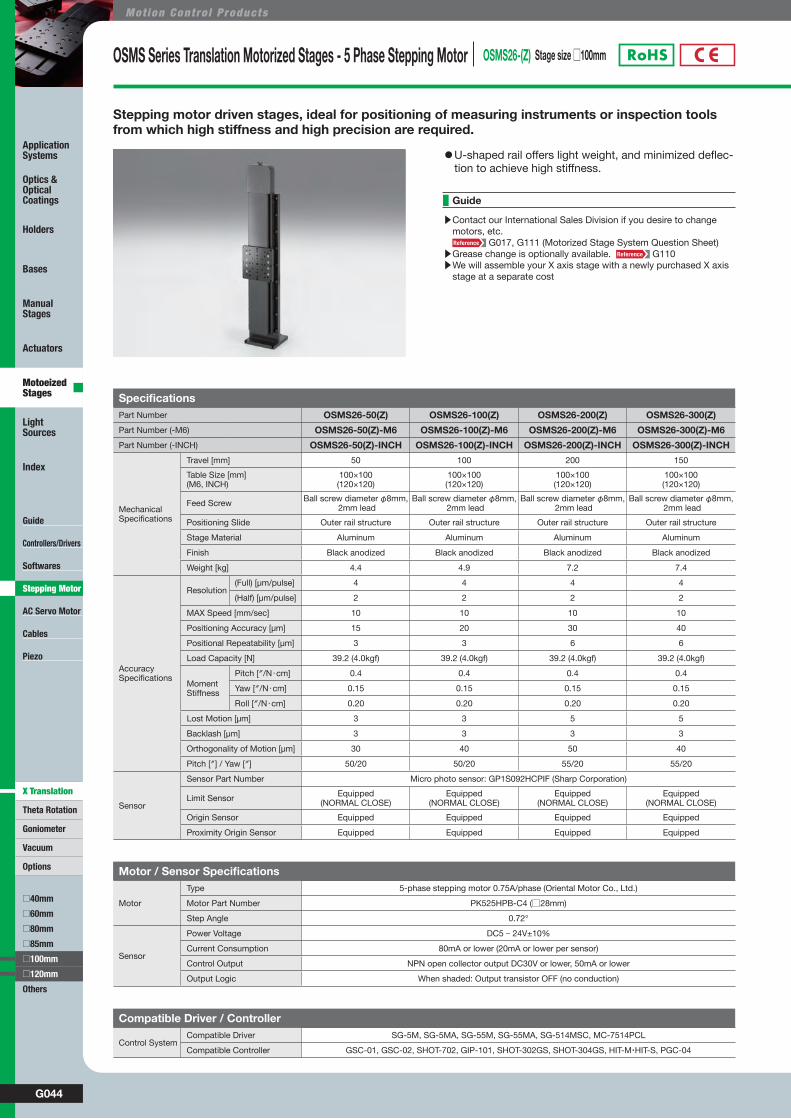
OSMS Series Translation Motorized Stages - 5 Phase Stepping Motor OSMS26-(Z) Stage size □100mm
SpecificationsPart Number OSMS26-50(Z) OSMS26-100(Z) OSMS26-200(Z) OSMS26-300(Z)
Part Number (-M6) OSMS26-50(Z)-M6 OSMS26-100(Z)-M6 OSMS26-200(Z)-M6 OSMS26-300(Z)-M6
Part Number (-INCH) OSMS26-50(Z)-INCH OSMS26-100(Z)-INCH OSMS26-200(Z)-INCH OSMS26-300(Z)-INCH
MechanicalSpecifications
Travel [mm] 50 100 200 150
Table Size [mm](M6, INCH)
100×100(120×120)
100×100(120×120)
100×100(120×120)
100×100(120×120)
Feed Screw Ball screw diameter φ8mm, 2mm lead
Ball screw diameter φ8mm, 2mm lead
Ball screw diameter φ8mm, 2mm lead
Ball screw diameter φ8mm, 2mm lead
Positioning Slide Outer rail structure Outer rail structure Outer rail structure Outer rail structure
Stage Material Aluminum Aluminum Aluminum Aluminum
Finish Black anodized Black anodized Black anodized Black anodized
Weight [kg] 4.4 4.9 7.2 7.4
AccuracySpecifications
Resolution (Full) [μm/pulse] 4 4 4 4
(Half) [μm/pulse] 2 2 2 2
MAX Speed [mm/sec] 10 10 10 10
Positioning Accuracy [μm] 15 20 30 40
Positional Repeatability [μm] 3 3 6 6
Load Capacity [N] 39.2 (4.0kgf) 39.2 (4.0kgf) 39.2 (4.0kgf) 39.2 (4.0kgf)
Moment Stiffness
Pitch [″/N・cm] 0.4 0.4 0.4 0.4
Yaw [″/N・cm] 0.15 0.15 0.15 0.15
Roll [″/N・cm] 0.20 0.20 0.20 0.20
Lost Motion [μm] 3 3 5 5
Backlash [μm] 3 3 3 3
Orthogonality of Motion [μm] 30 40 50 40
Pitch [″] / Yaw [″] 50/20 50/20 55/20 55/20
Sensor
Sensor Part Number Micro photo sensor: GP1S092HCPIF (Sharp Corporation)
Limit Sensor Equipped(NORMAL CLOSE)
Equipped(NORMAL CLOSE)
Equipped(NORMAL CLOSE)
Equipped(NORMAL CLOSE)
Origin Sensor Equipped Equipped Equipped Equipped
Proximity Origin Sensor Equipped Equipped Equipped Equipped
Motor / Sensor Specifications
Motor
Type 5-phase stepping motor 0.75A/phase (Oriental Motor Co., Ltd.)
Motor Part Number PK525HPB-C4 (□28mm)
Step Angle 0.72°
Sensor
Power Voltage DC5 - 24V±10%
Current Consumption 80mA or lower (20mA or lower per sensor)
Control Output NPN open collector output DC30V or lower, 50mA or lower
Output Logic When shaded: Output transistor OFF (no conduction)
Compatible Driver / Controller
Control SystemCompatible Driver SG-5M, SG-5MA, SG-55M, SG-55MA, SG-514MSC, MC-7514PCL
Compatible Controller GSC-01, GSC-02, SHOT-702, GIP-101, SHOT-302GS, SHOT-304GS, HIT-M・HIT-S, PGC-04
Stepping motor driven stages, ideal for positioning of measuring instruments or inspection tools from which high stiffness and high precision are required.
▶Contact our International Sales Division if you desire to change motors, etc.
G017, G111 (Motorized Stage System Question Sheet)▶Grease change is optionally available. G110▶We will assemble your X axis stage with a newly purchased X axis
stage at a separate cost
Guide
◦U-shaped rail offers light weight, and minimized deflec-tion to achieve high stiffness.
G045WEB http://www.sigma-koki.com/english/ E-mail [email protected] TEL +81-3-5638-8228 FAX +81-3-5638-6550
Guide
Controllers/Drivers
Softwares
AC Servo Motor
Cables
Piezo
Theta Rotation
Goniometer
Vacuum
Options
□40mm
□60mm
□80mm
□85mm
Others
Application Systems
Optics & Optical Coatings
Holders
Bases
Manual Stages
Actuators
Motoeized Stages
Light Sources
Index
□120mm
□100mm
X Translation
Stepping Motor
W9069CatalogCode
Outline Drawing
Stage
Driver
Drivers
Cable
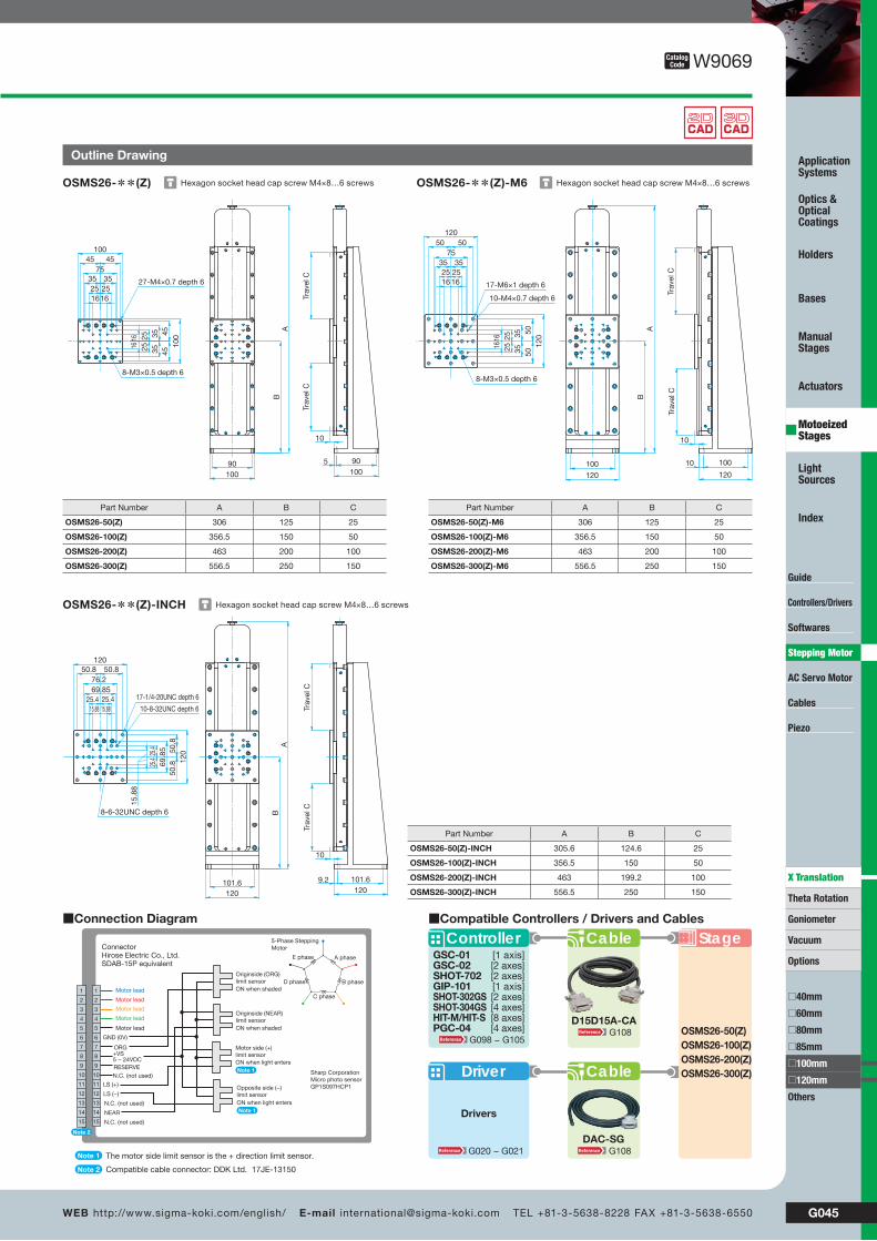
ControllerGSC-01GSC-02SHOT-702GIP-101SHOT-302GSSHOT-304GSHIT-M/HIT-SPGC-04
[1 axis][2 axes][2 axes][1 axis][2 axes][4 axes][8 axes][4 axes]
Cable
OSMS26-50(Z)OSMS26-100(Z)OSMS26-200(Z)OSMS26-300(Z)
■Compatible Controllers / Drivers and Cables
DAC-SG
D15D15A-CA
G108G020 − G021
G098 − G105G108
Hexagon socket head cap screw M4×8…6 screwsOSMS26-**(Z) Hexagon socket head cap screw M4×8…6 screwsOSMS26-**(Z)-M6
Hexagon socket head cap screw M4×8…6 screwsOSMS26-**(Z)-INCH
BA
90 90100
5
100
Trav
el C
Trav
el C
10
100
100
2516
16
16
162525
35
35
35
35
25
45
45
45
45
8-M3×0.5 depth 6
27-M4×0.7 depth 6
75
120
120
16
16
16
162525
35
35
35
35
2525
50
50
50
50
10010
120
100120
Trav
el C
Trav
el C
10
BA
8-M3×0.5 depth 6
10-M4×0.7 depth 6
17-M6×1 depth 6
75
120
120
69.85
69.8
550
.850
.8
25.4
25.4
50.8 50.8
25.4 25.415.88 15.88
15.8
8
101.69.2120120
101.6
AB
Trav
el C
Trav
el C
10
10-8-32UNC depth 6
17-1/4-20UNC depth 6
8-6-32UNC depth 6
76.2
■Connection Diagram
Motor lead
Motor lead
Motor lead
Motor lead
Motor lead
ORG+VS5 − 24VDCRESERVE
LS (+)
LS (−)
Connector Hirose Electric Co., Ltd.SDAB-15P equivalent
Sharp CorporationMicro photo sensorGP1S097HCP1
1
2
3
4
5
6
7
8
9
10
11
12
13
14
15
1
2
3
4
5
6
7
8
9
10
11
12
13
14
15 N.C. (not used)
N.C. (not used)
NEAR
GND (0V)
N.C. (not used)
A phase
B phase
C phase
D phase
E phase
5-Phase SteppingMotor
Note 2
Note 1
Note 2
The motor side limit sensor is the + direction limit sensor.
Compatible cable connector: DDK Ltd. 17JE-13150
Originside (ORG)limit sensorON when shaded
Originside (NEAR)limit sensorON when shaded
Opposite side (−)limit sensorON when light entersNote 1
Motor side (+)limit sensorON when light entersNote 1
Part Number A B C
OSMS26-50(Z) 306 125 25
OSMS26-100(Z) 356.5 150 50
OSMS26-200(Z) 463 200 100
OSMS26-300(Z) 556.5 250 150
Part Number A B C
OSMS26-50(Z)-M6 306 125 25
OSMS26-100(Z)-M6 356.5 150 50
OSMS26-200(Z)-M6 463 200 100
OSMS26-300(Z)-M6 556.5 250 150
Part Number A B C
OSMS26-50(Z)-INCH 305.6 124.6 25
OSMS26-100(Z)-INCH 356.5 150 50
OSMS26-200(Z)-INCH 463 199.2 100
OSMS26-300(Z)-INCH 556.5 250 150

G046
Mot ion Cont ro l Products
Guide
Controllers/Drivers
Softwares
AC Servo Motor
Cables
Piezo
Theta Rotation
Goniometer
Vacuum
Options
□40mm
□60mm
□80mm
□85mm
Others
Application Systems
Optics & Optical Coatings
Holders
Bases
Manual Stages
Actuators
Motoeized Stages
Light Sources
Index
□120mm
□100mm
X Translation
Stepping Motor
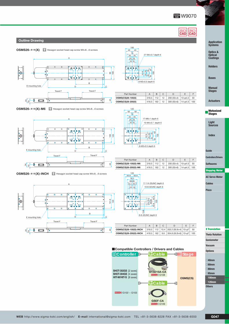
Precision Motorized Stages with Built-in Compact Scale OSMS(CS)26-(X) Stage size □100mm
SpecificationsPart Number OSMS(CS)26-100(X) OSMS(CS)26-200(X)
Part Number (-M6) OSMS(CS)26-100(X)-M6 OSMS(CS)26-200(X)-M6
Part Number (-INCH) OSMS(CS)26-100(X)-INCH OSMS(CS)26-200(X)-INCH
MechanicalSpecifications
Travel [mm] 100 200
Table Size [mm](M6, INCH)
100×100(120×120)
100×100(120×120)
Feed Screw Ball screw diameter φ8mm, 2mm lead Ball screw diameter φ8mm, 2mm lead
Positioning Slide Outer rail structure Outer rail structure
Stage Material Aluminum Aluminum
Finish Black anodized Black anodized
Weight [kg] 3.2 4.3
AccuracySpecifications
Resolution (Full) [μm/pulse] 4 4
(Half) [μm/pulse] 2 2
MAX Speed [mm/sec] 40 40
Positioning Accuracy [μm] 10 15
Positional Repeatability [μm] 2 3
Load Capacity [N] 117 (12.0kgf) 117 (12.0kgf)
Moment Stiffness
Pitch [″/N・cm] 0.23 0.23
Yaw [″/N・cm] 0.12 0.12
Roll [″/N・cm] 0.2 0.2
Lost Motion [μm] 3 5
Backlash [μm] 3 3
Parallelism [μm] 50 50
Running Parallelism [μm] 10 10
Pitch [″] / Yaw [″] 25/20 30/25
Sensor
Sensor Part Number Micro photo sensor: GP1S092HCPIF (Sharp Corporation)
Limit Sensor Equipped (NORMAL CLOSE) Equipped (NORMAL CLOSE)
Origin Sensor Equipped Equipped
Proximity Origin Sensor Equipped Equipped
Scale head Resolution [μm] 0.5 0.5
Motor / Sensor Specifications
Motor
Type 5-phase stepping motor 0.75A/phase (Oriental Motor Co., Ltd.)
Motor Part Number PK525HPB-C4 (□28mm)
Step Angle 0.72°
Sensor
Power Voltage DC5 - 24V±10%
Current Consumption 80mA or lower (20mA or lower per sensor)
Control Output NPN open collector output DC30V or lower, 50mA or lower
Output Logic When shaded: Output transistor OFF (no conduction)
Scale head Power Voltage / Current Consumption DC5V±25% / 50mA
Compatible Driver / Controller
Control SystemCompatible Driver −Compatible Controller SHOT-302GS, SHOT-304GS, HIT-M・HIT-S
Compatible Cable
CableDriver Cable D15D15A-CA
Scale Cable GSEF-CA-3
The dedicated stage controllers (SHOT-302GS/304GS, HIT series) offer a full closed loop system with high precision and high reliability.
▶Contact our International Sales Division for replacement of motors or for stabilizing (drop-preventing) mechanism.
G017, G111 (Motorized Stage System Question Sheet)▶Grease change is optionally available. G110▶Contact our International Sales Division to use the stage as an XY
axis or a Z axis stage.
Guide
◦The stages enable high stiffness and high precision posi-tioning because their structure, which is strong against momentum and combined load, is less susceptible to pitch-ing, rolling and yawing.
◦A compact scale is built in, but the installation space is the same as that of other OSMS series when the travel is the same.
G047WEB http://www.sigma-koki.com/english/ E-mail [email protected] TEL +81-3-5638-8228 FAX +81-3-5638-6550
Guide
Controllers/Drivers
Softwares
AC Servo Motor
Cables
Piezo
Theta Rotation
Goniometer
Vacuum
Options
□40mm
□60mm
□80mm
□85mm
Others
Application Systems
Optics & Optical Coatings
Holders
Bases
Manual Stages
Actuators
Motoeized Stages
Light Sources
Index
□120mm
□100mm
X Translation
Stepping Motor
Hexagon socket head cap screw M4×8…6 screwsOSMS26-**(X)
Hexagon socket head cap screw M4×8…6 screwsOSMS26-**(X)-M6
Hexagon socket head cap screw M4×8…6 screwsOSMS26-**(X)-INCH
A
D
B
1934
Travel F Travel F
43
10045 45
35 3525 2516 16
100
454535
35252516
16
C
90 100
E mounting hole
27-M4×0.7 depth 6
8-M3×0.5 depth 6
75
120
120
50 50
35 3525 25
1616
5050
2525
3535
1616
A
120
100
CD
B
43
1934
Travel FTravel F
8-M3×0.5 depth 6
10-M4×0.7 depth 6
17-M6×1 depth 6
E mounting hole
75
120
120
15.88 15.88
15.8
8
25.425.4
69.8
5
69.85
25.4
25.4
76.2
50.8
50.8
50.8
50.8
A
B
CD
101.
6
120
1934
Travel FTravel F
43
10-8-32UNC depth 6
17-1/4-20UNC depth 6
8-6-32UNC depth 6E mounting hole
W9070CatalogCode
Outline Drawing
Part Number A B C D E F
OSMS(CS)26-100(X) 318.5 112 12 200 (50×4) 10-φ4.5 50
OSMS(CS)26-200(X) 418.5 162 12 300 (50×6) 14-φ4.5 100
Part Number A B C D E F
OSMS(CS)26-100(X)-M6 318.5 112 12 200 (50×4) 10-φ4.5 50
OSMS(CS)26-200(X)-M6 418.5 162 12 300 (50×6) 14-φ4.5 100
Part Number A B C D E F
OSMS(CS)26-100(X)-INCH 318.5 112 10.4 203.2 (50.8×4) 10-φ7 50
OSMS(CS)26-200(X)-INCH 418.5 162 9.6 304.8 (50.8×6) 10-φ7 100
GSEF-CA
D15D15A-CA
Stage
Cable
Controller
SHOT-302GSSHOT-304GSHIT-M/HIT-S
[2 axes][4 axes][8 axes]
Cable
OSMS(CS)
■Compatible Controllers / Drivers and Cables
G108
G109
G102 − G103
G048
Mot ion Cont ro l Products
Guide
Controllers/Drivers
Softwares
AC Servo Motor
Cables
Piezo
Theta Rotation
Goniometer
Vacuum
Options
□40mm
□60mm
□80mm
□85mm
□100mm
Others
Application Systems
Optics & Optical Coatings
Holders
Bases
Manual Stages
Actuators
Motoeized Stages
Light Sources
Index
□120mm
X Translation
Stepping Motor
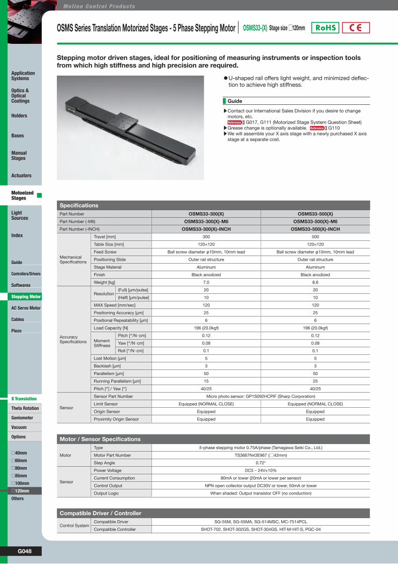
OSMS Series Translation Motorized Stages - 5 Phase Stepping Motor OSMS33-(X) Stage size □120mm
Stepping motor driven stages, ideal for positioning of measuring instruments or inspection tools from which high stiffness and high precision are required.
SpecificationsPart Number OSMS33-300(X) OSMS33-500(X)
Part Number (-M6) OSMS33-300(X)-M6 OSMS33-500(X)-M6
Part Number (-INCH) OSMS33-300(X)-INCH OSMS33-500(X)-INCH
MechanicalSpecifications
Travel [mm] 300 500
Table Size [mm] 120×120 120×120
Feed Screw Ball screw diameter φ10mm, 10mm lead Ball screw diameter φ10mm, 10mm lead
Positioning Slide Outer rail structure Outer rail structure
Stage Material Aluminum Aluminum
Finish Black anodized Black anodized
Weight [kg] 7.0 8.6
AccuracySpecifications
Resolution (Full) [μm/pulse] 20 20
(Half) [μm/pulse] 10 10
MAX Speed [mm/sec] 120 120
Positioning Accuracy [μm] 25 25
Positional Repeatability [μm] 6 6
Load Capacity [N] 196 (20.0kgf) 196 (20.0kgf)
Moment Stiffness
Pitch [″/N・cm] 0.12 0.12
Yaw [″/N・cm] 0.08 0.08
Roll [″/N・cm] 0.1 0.1
Lost Motion [μm] 5 5
Backlash [μm] 3 3
Parallelism [μm] 50 50
Running Parallelism [μm] 15 25
Pitch [″] / Yaw [″] 40/25 40/25
Sensor
Sensor Part Number Micro photo sensor: GP1S092HCPIF (Sharp Corporation)
Limit Sensor Equipped (NORMAL CLOSE) Equipped (NORMAL CLOSE)
Origin Sensor Equipped Equipped
Proximity Origin Sensor Equipped Equipped
Motor / Sensor Specifications
Motor
Type 5-phase stepping motor 0.75A/phase (Tamagawa Seiki Co., Ltd.)
Motor Part Number TS3667N43E967 (□42mm)
Step Angle 0.72°
Sensor
Power Voltage DC5 - 24V±10%
Current Consumption 80mA or lower (20mA or lower per sensor)
Control Output NPN open collector output DC30V or lower, 50mA or lower
Output Logic When shaded: Output transistor OFF (no conduction)
Compatible Driver / Controller
Control SystemCompatible Driver SG-55M, SG-55MA, SG-514MSC, MC-7514PCL
Compatible Controller SHOT-702, SHOT-302GS, SHOT-304GS, HIT-M・HIT-S, PGC-04
◦U-shaped rail offers light weight, and minimized deflec-tion to achieve high stiffness.
▶Contact our International Sales Division if you desire to change motors, etc.
G017, G111 (Motorized Stage System Question Sheet)▶Grease change is optionally available. G110▶We will assemble your X axis stage with a newly purchased X axis
stage at a separate cost.
Guide
G049WEB http://www.sigma-koki.com/english/ E-mail [email protected] TEL +81-3-5638-8228 FAX +81-3-5638-6550
Guide
Controllers/Drivers
Softwares
AC Servo Motor
Cables
Piezo
Theta Rotation
Goniometer
Vacuum
Options
□40mm
□60mm
□80mm
□85mm
□100mm
Others
Application Systems
Optics & Optical Coatings
Holders
Bases
Manual Stages
Actuators
Motoeized Stages
Light Sources
Index
□120mm
X Translation
Stepping Motor
W9071CatalogCode
Outline Drawing
CableController StageSHOT-702SHOT-302GSSHOT-304GSHIT-M/HIT-SPGC-04
[2 axes][2 axes][4 axes][8 axes][4 axes]
CableDriver
DAC-SG
■Compatible Controllers / Drivers and Cables
OSMS33‐300(X)OSMS33‐500(X)
Drivers
D15D15A-CAG100 − G105
G020 − G021
G108
G108
Hexagon socket head cap screw M5×10…4 screwsOSMS33-**(X)
Hexagon socket head cap screw M5×10…4 screwsOSMS33-**(X)-M6
Hexagon socket head cap screw M5×10…4 screwsOSMS33-**(X)-INCH
A
B
Travel F Travel F
12050 5035 3525 25
120
505035
352525
56.7
2648.7
CD
120
100
9-M6×1 depth 8
16-M4×0.7 depth 8
E mounting hole
120
120
25
25
25
25
35
35
35
3550 50
5050
120
100
A
B
CD
2648.7
Travel F Travel F
56.7
8-M4×0.7 depth 8
8-M6×1 depth 8
9-M6×1 depth 8
E mounting hole
120
120
34.925
34.92
25.4
25.4
34.92525
.4
25.434.9350.8 50.8
50.8
50.8
A
BCD
120
101.
6
2648.7
Travel FTravel F
56.7
9-1/4-20UNC depth 8
8-#8-32UNC depth 8
8-1/4-20UNC depth 8
E mounting hole
■Connection Diagram
Motor lead
Motor lead
Motor lead
Motor lead
Motor lead
ORG+VS5 − 24VDCRESERVE
LS (+)
LS (−)
Connector Hirose Electric Co., Ltd.SDAB-15P equivalent
Sharp CorporationMicro photo sensorGP1S097HCP1
1
2
3
4
5
6
7
8
9
10
11
12
13
14
15
1
2
3
4
5
6
7
8
9
10
11
12
13
14
15 N.C. (not used)
N.C. (not used)
NEAR
GND (0V)
N.C. (not used)
A phase
B phase
C phase
D phase
E phase
5-Phase SteppingMotor
Note 2
Note 1
Note 2
The motor side limit sensor is the + direction limit sensor.
Compatible cable connector: DDK Ltd. 17JE-13150
Originside (ORG)limit sensorON when shaded
Originside (NEAR)limit sensorON when shaded
Opposite side (−)limit sensorON when light entersNote 1
Motor side (+)limit sensorON when light entersNote 1
Part Number A B C D E F
OSMS33-300(X)-INCH 530.3 211.8 59.4 304.8 (50.8×6) 14-φ7 150
OSMS33-500(X)-INCH 730.3 311.8 57.8 508 (50.8×10) 22-φ7 250
Part Number A B C D E F
OSMS33-300(X)-M6 530.3 211.8 61.8 300 (50×6) 14-φ6.5 150
OSMS33-500(X)-M6 730.3 311.8 61.8 500 (50×10) 22-φ6.5 250
Part Number A B C D E F
OSMS33-300(X) 530.3 211.8 61.8 300 (50×6) 14-φ6.5 150
OSMS33-500(X) 730.3 311.8 61.8 500 (50×10) 22-φ6.5 250

G050
Mot ion Cont ro l Products
Guide
Controllers/Drivers
Softwares
AC Servo Motor
Cables
Piezo
Theta Rotation
Goniometer
Vacuum
Options
□40mm
□60mm
□80mm
□85mm
□100mm
Others
Application Systems
Optics & Optical Coatings
Holders
Bases
Manual Stages
Actuators
Motoeized Stages
Light Sources
Index
□120mm
X Translation
Stepping Motor
OSMS Series Translation Motorized Stages - 5 Phase Stepping Motor OSMS33-(XY) Stage size □120mm
SpecificationsPart Number OSMS33-300(XY) OSMS33-500(XY)Part Number (-M6) OSMS33-300(XY)-M6 OSMS33-500(XY)-M6Part Number (-INCH) OSMS33-300(XY)-INCH OSMS33-500(XY)-INCH
MechanicalSpecifications
Travel [mm] 300 500
Table Size [mm] 120×120 120×120
Feed Screw Ball screw diameter φ10mm, 10mm lead Ball screw diameter φ10mm, 10mm lead
Positioning Slide Outer rail structure Outer rail structure
Stage Material Aluminum Aluminum
Finish Black anodized Black anodized
Weight [kg] 14.0 17.2
AccuracySpecifications
Resolution (Full) [μm/pulse] 20 20
(Half) [μm/pulse] 10 10
MAX Speed [mm/sec] 80 80
Load Capacity [N] 156 (16.0kgf) 156 (16.0kgf)
Backlash [μm] 3 3
Orthogonality of Motion [μm] 5 5
Sensor
Sensor Part Number Micro photo sensor: GP1S092HCPIF(Sharp Corporation)
Limit Sensor Equipped (NORMAL CLOSE) Equipped (NORMAL CLOSE)
Origin Sensor None None
Proximity Origin Sensor None None
(Reference) Precision Specifications of Single Axis StagePart Number OSMS33-300(X) OSMS33-500(X)
AccuracySpecifications
Positioning Accuracy [μm] 15 20
Positional Repeatability [μm] 6 6
Moment Stiffness
Pitch [″/N・cm] 0.12 0.12
Yaw [″/N・cm] 0.08 0.08
Roll [″/N・cm] 0.08 0.08
Lost Motion [μm] 5 5
Parallelism [μm] 50 50
Running Parallelism [μm] 10 10
Motor / Sensor Specifications
Motor
Type 5-phase stepping motor 0.75A/phase (Tamagawa Seiki Co., Ltd.)
Motor Part Number TS3667N43E967 (□42mm)
Step Angle 0.72°
Sensor
Power Voltage DC5 - 24V±10%
Current Consumption 40mA or lower (20mA or lower per sensor)
Control Output NPN open collector output DC30V or lower, 50mA or lower
Output Logic When shaded: Output transistor OFF (no conduction)
Compatible Driver / Controller
Control SystemCompatible Driver SG-55M, SG-55MA, SG-514MSC, MC-7514PCL
Compatible Controller SHOT-702, SHOT-302GS, SHOT-304GS, HIT-M・HIT-S, PGC-04
Stepping motor driven stages, ideal for positioning of measuring instruments or inspection tools from which high stiffness and high precision are required.
◦U-shaped rail offers light weight, and minimized deflec-tion to achieve high stiffness.
▶Contact our International Sales Division if you desire to change motors, etc.
G017, G111 (Motorized Stage System Question Sheet)▶Grease change is optionally available. G110▶We will assemble your X axis stage with a newly purchased X axis
stage at a separate cost.
Guide