mullaly engineering - water services association of … 4994:1997 - specification for design and...
TRANSCRIPT
WSAA Product Appraisal 1020 Issue 2 1
COPYRIGHT
Mullaly Engineering PRODUCT APPRAISAL REPORT 1020 Issue 2
FRP Packaged Pump Stations and Emergency Storage Tanks
AS 2634:1983 - Chemical plant equipment made from glass-fiber reinforced plastics (GRP) based on thermosetting resins
BS 4994:1997 - Specification for design and construction of vessels and tanks in reinforced plastics
WSA 129:2011 - Industry Standard for Plastics Collection Tanks for Pressure and Vacuum Sewers
AS 1170.1:1981 - Minimum Design Loads on Structures - Dead and Live loads
WSA 04:2005 Version 2.1 - Sewage Pumping Station Code of Australia Publication date: 30 November 2015
WSAA Product Appraisal 1020 Issue 2 2
COPYRIGHT
Document History
The following information indicates the changes made to this document.
Date Version File Location
24/03/2014 Peer Review Draft
U:\PP1 Industry Performance and Regulation\PP1-012 Product Appraisals\Civil Asset Infrastructure\2010\PA 1020 Mullaly FRP Packaged Pump Stations\WSAA PA 10_20 Mullaly FRP Packaged Pump Stations 12-3-14.docx
28/05/2014 Publication Issue 1
U:\PP1 Industry Performance and Regulation\PP1- 012 Product Appraisals\Civil Asset Infrastructure\2010\PA 1020 Mullaly FRP Packaged Pump Stations\Final\WSAA PA 10_20 Mullaly FRP Packaged Pump Stations final 25-5-14.docx
28/10/2015 Peer Review Issue 2
U:\PP1 Industry Performance and Regulation\PP1-012 Product Appraisals\Civil Asset Infrastructure\2015\PA 1020 Issue 2 Mullaly Engineering - FRP Pump Stations and FRP Emergency Storage Tank\WSAA PA 10_20 Mullaly FRP Pump Stations Issue 2 20-8-15.docx
30/11/2015 Publication
U:\PP1 Industry Performance and Regulation\PP1-012 Product Appraisals\Civil Asset Infrastructure\2015\PA 1020 Issue 2 Mullaly Engineering - FRP Pump Stations and FRP Emergency Storage Tank\WSAA PA 10_20 Mullaly FRP Pump Stations Issue 2 final.docx
Peer Reviewers
Name/Title Organisation Date
IPAM Expert Panel Infrastructure Products and Material Community of Practice
19/11/2015
Carl Radford, Product Appraisal Manager WSAA 12/03/2014
David Moore, Design Manager City West Water 06/05/2014
Colin Paxman, Manager Products and Standards South East Water 23/05/2014
Mohamed Yoosuf, Senior Standards Engineer City West Water 13/05/2014
Approvals
Name/Title Signature Date
Carl Radford, Product Appraisal Manager Carl Radford 12/03/2014
Carl Radford, Product Appraisal Manager Carl Radford 28/05/2014
Carl Radford, Product Appraisal Manager Carl Radford 30/11/2015

WSAA Product Appraisal 1020 Issue 2 3
COPYRIGHT
Overview of WSAA
The Water Services Association of Australia (WSAA) is the peak industry body that supports
the Australian Urban Water Industry. Its members and associate members provide water and
sewerage services to approximately 20 million Australians and many of Austra lia’s largest
industrial and commercial enterprises.
The Association facilitates collaboration, knowledge sharing, networking and cooperation
within the urban water industry. It is proud of the collegiate attitude of its members which
has led to industry-wide approaches to national water issues.
WSAA can demonstrate success in the standardisation of industry performance monitoring
and benchmarking, as well as many research outcomes of national significance. The WSAA
Executive retains strong links with policy makers and legislative bodies and their influences,
to monitor emerging issues of importance to the urban water industry. WSAA is regularly
consulted and its advice sought by decision makers when developing strategic directions for
the water industry.
WSAA was formed in 1995 as a non-profit organisation to foster the exchange of information
relating to the provision of urban water services between industry, government and the
community, and to promote sustainable water resource management.
The Association’s main activities focus on four areas:
1. Influencing national and state policies on the provision of urban water services and
sustainable water resource management;
2. Promoting debate on environmentally sustainable development and management of
water resources and the community health requirements of public water supplies;
3. Improving industry performance and establishing benchmarks and industry leading
practices for water service processes; and
4. Fostering the exchange of information on education, training, research, water and
wastewater management and treatment and other matters of common interest
Copyright
This document is copyrighted. Apart from any use as permitted under the Copyright Act
1968, no part of this document may be reproduced or transmitted in any form or by any
means, electronically or mechanical, for any purpose, without the express written permission
of Water Services Association of Australia Limited.
© Copyright 2015 by WATER SERVICES ASSOCIATION of Australia Limited All rights
reserved.

WSAA Product Appraisal 1020 Issue 2 4
COPYRIGHT
CONTENTS
1 EXECUTIVE SUMMARY ............................................................................................................................................. 6
1.1 Recommendations ................................................................................................................................................ 7
2 MANUFACTURER AND DISTRIBUTION OVERVIEW ................................................................................................ 8
2.1 FRP Vessel Manufacturer ..................................................................................................................................... 8
2.2 Distributor / Supplier .............................................................................................................................................. 8
3 THE PRODUCT ........................................................................................................................................................... 8
3.1 FRP Vessel ......................................................................................................................................................... 12
3.2 FRP Vessel manufacturing method ..................................................................................................................... 12
3.3 Thickness of the corrosion barrier to FRP exposed surfaces .............................................................................. 12
3.4 Jointing options ................................................................................................................................................... 12
3.5 Access Covers and safety grates ........................................................................................................................ 13
4 SCOPE OF THE APPRAISAL ................................................................................................................................... 13
5 APPRAISAL CRITERIA ............................................................................................................................................. 13
5.1 Quality Assurance Requirements ........................................................................................................................ 13
5.2 Performance Requirements................................................................................................................................. 13
5.2.1 Product Manufacturing Standards ................................................................................................................ 13
6 COMPLIANCE WITH APPRAISAL CRITERIA........................................................................................................... 14
6.1 Compliance with Quality Assurance Requirements ............................................................................................. 14
6.1.1 FRP Vessel supplier ..................................................................................................................................... 14
6.1.2 Suppliers for Wet-well and valve pit access covers ...................................................................................... 14
6.2 Compliance with Performance Requirements ..................................................................................................... 15
6.2.1 FRP Material Components ............................................................................................................................ 17
6.2.2 Type Tests .................................................................................................................................................... 17
6.2.3 Batch Release Tests ..................................................................................................................................... 19
6.2.4 Additional Assessments on FRP Vessel and Valve Pit ................................................................................. 20
6.2.5 FRP Packaged Pump Station – Buoyancy Consideration............................................................................. 24
6.2.6 Attachments .................................................................................................................................................. 26
6.2.7 Review of the documentation and guidance for designers, installers and operatives ................................... 26
7 WSAA NETWORK REQUESTS ................................................................................................................................ 26
8 INSTALLATION, REPAIR, MAINTENANCE AND TRAINING .................................................................................... 31
8.1 Repair Procedure ................................................................................................................................................ 31
8.2 Maintenance Procedure ...................................................................................................................................... 31
8.3 Training Requirements ........................................................................................................................................ 32
8.4 Backfill Requirement ........................................................................................................................................... 32
9 PRODUCT MARKING ............................................................................................................................................... 32
10 PACKAGING AND TRANSPORTATION ................................................................................................................. 33
11 PRODUCT WARRANTY .......................................................................................................................................... 33
12 WATER AGENCY EXPERIENCE WITH THE PRODUCT OR FIELD TESTING REPORT ..................................... 33
12.1 FRP Pump Station ............................................................................................................................................. 33
12.1.1 Power and Water Authority (PAWA) NT ..................................................................................................... 33
12.1.2 Bingarra Gorge Estate - Wilton NSW .......................................................................................................... 33
12.1.3 Cooktown - North QLD ................................................................................................................................ 33
WSAA Product Appraisal 1020 Issue 2 5
COPYRIGHT
12.1.4 Innes Estate – Townsville North QLD ......................................................................................................... 34
12.1.5 Docker River Aboriginal Community, NT .................................................................................................... 34
12.1.6 Sydney Water ............................................................................................................................................. 34
12.1.7 Cairns Regional Council Waste Water ........................................................................................................ 35
12.1.8 Townsville City Council ............................................................................................................................... 35
12.1.9 Mackay Regional Council ........................................................................................................................... 35
12.1.10 Hughenden Shire Council ......................................................................................................................... 35
12.2 FRP Emergency Storage Tank .......................................................................................................................... 35
13 DISCUSSION ........................................................................................................................................................... 36
14 LIFE EXPECTANCY UNDER VARIOUS OPERATIONAL CONDITIONS ............................................................... 36
15 FUTURE WORKS .................................................................................................................................................... 37
16 REPORT RECOMMENDATIONS ............................................................................................................................ 37
17 DISCLAIMER .......................................................................................................................................................... 37
17.1 Issue of Report .................................................................................................................................................. 38
17.2 Limits on Reliance on Information and Recommendations................................................................................ 38
17.2.1 Disclaimer of liability ................................................................................................................................... 38
17.2.2 Need for independent assessment ............................................................................................................. 38
17.3 No Updating ...................................................................................................................................................... 38
17.4 No Warranty ...................................................................................................................................................... 38
APPENDIX A – TECHNICAL MANUAL ........................................................................................................................ 39
APPENDIX B - QUALITY ASSURANCE CERTIFICATES ............................................................................................ 40
APPENDIX C – VISUAL INSPECTION REPORTS AND DESIGN VERIFICATION STATEMENTS ISSUED BY THE COMPOSITE DESIGN ENGINEER ................................................................................................................ 42
APPENDIX D - MULLALY FRP PACKAGED PUMP STATION – BALLAST CALCULATION ...................................... 46
APPENDIX E - WSAA PRODUCT SPECIFICATION .................................................................................................... 49
APPENDIX F – PACKAGING AND TRANSPORTATION ............................................................................................. 50
APPENDIX G – WARRANTY FOR MULLALY FRP PUMP STATION .......................................................................... 56
APPENDIX H – COUNCIL & WATER AUTHORITIES PRODUCT AUTHORISATION CERTIFICATES ...................... 58
APPENDIX I - SUPPLIER CONTACTS ........................................................................................................................ 63

WSAA Product Appraisal 1020 Issue 2 6
COPYRIGHT
1 EXECUTIVE SUMMARY
Issue 2 of this Product Appraisal Report replaces and updates PA 10/20 Issue 1 published
on 29 May 2014.
The following amendments have been made in Issue 2:
a) The Mullaly FRP Emergency Storage Tanks in various sizes from 1453 mm to 3137 mm
in diameter and from 3.3 m to 15 m in length (5,000 to 110,000 litres capacity) have been
included in this appraisal.
b) The scope of work now covers the use of Mullaly FRP Pump Station and Emergency
Storage Tank in Sewerage Networks and Alternative Water Supply (i.e. Storm water).
c) Inclusion of updated version of “Installation Instructions for Mullaly FRP Pump Station”
identified as Future Work Item in Section 15 of Issue 1. The below clause has been
inserted into the latest version:
“where an installation is to be carried out by a company or persons not previously
experienced in the installation of a Mullaly Engineering FRP packaged pump station, it is
a requirement for one of the Mullaly Engineering or their experienced agent’s staff to
attend on the site during the installation to provide training and to ensure the installation
is carried out in accordance with Mullaly’s installation instructions and to meet the
warranty requirements”.
d) Issue 1 consists of a main report and Addendum. As Mullaly Engineering consider some
of the appendices included in the main report and addendum contain commercially
sensitive documents, the Issue 2 has been prepared as follows:
A main report with seven appendices from A to I;
Addendum No. 1 with seven appendices from A1 to A6; and
Addendum No. 2 with five appendices from B1 to B8
As the Addendum No. 2 contains “Commercial-in-Confidence” documents, it can be
accessed with the consent of the Supplier.
Mullaly Engineering specialises in the supply of FRP (Fiber Reinforced Plastic) packaged
pumping stations and emergency storage tanks for individual Council or Water Agency
requirements across Australia.
Tank Solutions is the manufacturer of FRP vessels which are used in the wet wells, valve
chambers and emergency storage tanks supplied by Mullaly Engineering.
Tank Solutions manufactures an extensive range of tanks in steel and fibreglass for
underground, on ground and above ground applications. Tank Solutions manufactures FRP
tanks in Tomago (NSW) and has a sales office in VIC.
The Mullaly FRP Packaged Pumping Stations are available in various sizes from 1050 mm
to 3750 mm in diameter and from 1.5 m to 14 m in depth. The Mullaly FRP Emergency
Storage Tanks are available in various sizes from 1453 mm to 3137 mm in diameter and
from 3.3 m to 15 m in length (5,000 to 110,000 litres capacity).
Note: Internal diameters are specified for pump station and emergency storage tank.
However for the purposes of this appraisal WSAA has elected to assess the performance of
FRP pumping stations up to 3750 mm in diameter and 10 m in depth; and for FRP emergency
storage tanks up to 3137 mm in diameter and 15 m in length. Each FRP packaged pump
station and emergency storage tank is a single unit (i.e. wet well with an integral valve
chamber) or as separate wet well and external valve chamber, tailored for specific site
conditions rather than a ‘one size fits all’ standard solution. Mullaly Engineering offers
support to the Consultants and Contractors on all aspects of design, supply, installation ,
maintenance and commissioning.

WSAA Product Appraisal 1020 Issue 2 7
COPYRIGHT
FRP vessels are supplied as complete units. All joining of internal components is carried out
as part of the manufacturing process. No onsite joining or sealing is required as the pump
station is a one piece construction, fully pre-packaged and delivered to site ready for
placement into excavation. The project consultant and/or Water Agency are responsible for
determining the suitability of the station design for the local ground conditions.
A range of options and accessories (offered at fit out) are outlined in this appraisal to
demonstrate product versatility but are not intended to be included in the appraisal. The
project constructor will need to ensure that the specifications for covers, pumping equipment,
electrical controls and cubicle comply with relevant project documentation based upon the
individual Council or Water Agency standards. Each station can be designed with single or
multi-part cast iron covers Class B or D or aluminium covers.
The FRP vessels are designed to meet the requirements of:
AS 2634:1983 Chemical Plant Equipment made from Glass-Fibre Reinforced Plastics
(GRP) based on thermosetting resins; and
BS 4994:1997 Specification for design and construction of vessels and tanks in
Reinforced Plastic
The Mullaly FRP packaged pump station and emergency storage tank has been assessed
in line with WSA 129:2011 Industry Standard for Plastics Collection Tanks for Pressure and
Vacuum Sewers which is based on AS 2634:1983.
Two types of joints to external services are used; (a) Socket connections for PVC-U fittings;
and (b) Flange connections for all other materials.
Mullaly Engineering’s designs, manufacturing process and products are certified by an
independent composite engineering organisation called “Oceania Composite Engineering
Pty Ltd” whose Principal Mike Leggett is a Chartered Professional Engineer (CPEng
Membership No: 2696347) of Engineers Australia and Registered Professional Engineer of
Queensland (RPEQ, Registration No. 9566).
Mullaly Engineering manufactures solid FRP wall pump stations, not requiring attachment of
external strengthen ribs. The design thickness and manufacture methodology is supplied by
an independent third party Composite Engineer.
The storage tanks being horizontal are made under a design license from a company in
Canada and their design calls for the ribbed design. Ribs are integral to the manufacture
process and not added on to the outside after the tanks have been made.
The storage tanks are designed to take a horizontal load while the pump stations are
designed to take a vertical compression load.
The requirements of this appraisal have now been met with respect to general design
requirements, product type testing, auditing of production quality control systems, review of
documentation and guidance for designers, installers and operatives and the products are
seen as 'fit for purpose'.
1.1 Recommendations
It is recommended that WSAA Members and Associates, subject to any specific
requirements of the Member or Associate, accept or authorise the Mullaly range of FRP
Pumping Stations and Emergency Storage Tanks, as detailed in this report for use in
sewerage networks provided pipeline design, installation, acceptance testing and
commissioning are in accordance with relevant WSAA Codes, WSAA Member Integrated
Codes, and the manufacturer's requirements.
Water Agencies considering installing a Mullaly FRP Pumping Stations at depths greater
than 10 m are advised to consult with Mullaly Engineering.

WSAA Product Appraisal 1020 Issue 2 8
COPYRIGHT
2 MANUFACTURER AND DISTRIBUTION OVERVIEW
2.1 FRP Vessel Manufacturer
Tank Solutions manufactures the FRP vessels for the Mullaly range of FRP Pumping
Stations and Emergency Storage Tanks.
Until 30 June 2012, Tank Solutions has operated through three company names; Fibretank
Systems Pty Ltd, FTS Composites Pty Ltd and Tank Solutions Queensland. After buying out
‘Tank Solutions Queensland’ the company operates with a new name ; Tank Solutions Pty
Ltd from 1st July 2012 onwards.
Since 2000, Tank Solutions has been manufacturing an extensive range of tanks in steel
and fibreglass for underground, on ground and above ground applications. It has a new
location with two new ultra-modern workshops at Tomago NSW and has a sales office in
VIC.
Tank Solutions manufacturing plant in Tomago, NSW was purpose built less than 12 month
ago to produce tanks using a variety of technologies, from FRP moulding to Filament winding
to steel production. Tank Solutions currently manufacture both single and doubled walled
FRP tanks to storm water, sewerage, fuel and chemicals.
2.2 Distributor / Supplier
Mullaly Engineering has traded for over 40 years, but started contracting for the construction
of sewer and water pump stations after being in business with Sydney Water for eight years.
Mullaly Engineering has been providing a range of FRP systems for the water industry for
over 32 years. They manufacture packaged pump stations, wet wells, valve pits, metering
pits, overflow chambers and access chambers.
Mullaly Engineering commenced manufacturing packaged FRP pump stations in 1993. Since
this time pump stations have been supplied to over 300 different sites throughout Australia.
Ongoing development of the company’s products continues based on the installation
experiences of Mullaly Engineering, discussions with designers and feedback from end
users.
FRP components for sewerage works started to be used in Australia from the mid-1960s.
Some of the persons associated with the manufacture of Mullaly Engineering’s packaged
pump stations have over 30 years’ experience in FRP works in Australia. One of the early
projects they were associated was the construction of pipes for the ocean outfall at Shell
Harbour which are still in use.
Mullaly Engineering's designs, manufacturing process and products are certified by a third
party registered practicing Composite Engineer. Mullaly Engineering can provide expertise
at every stage of the process from design through to installation and maintenance.
Having its head office in Sydney, Mullaly Engineering is able to serve all Australian States
through its branch offices. Mullaly Engineering has distribution partners who can assist in
various Australian States and Territories.
For QLD, NT and WA - Professional Pump Services and Irrigation in Townsville
VIC, Southern NSW and SA - Mullaly Engineering Pty Ltd
3 THE PRODUCT
Mullaly Engineering markets a range of FRP pumping stations and emergency storage tanks.
Tank Solutions manufactures the FRP vessel as detailed in Clause 3.1.
Mullaly Engineering manufactures solid FRP wall pump stations, not requiring attachment of
external strengthen ribs. The design thickness and manufacture methodology is supplied by
an independent third party Composite Engineer.

WSAA Product Appraisal 1020 Issue 2 9
COPYRIGHT
The storage tanks being horizontal are made under a design license from a company in
Canada and their design calls for the ribbed design. Ribs are integral to the manufacture
process and not added on to the outside after the tanks have been made.
The storage tanks are designed to take a horizontal load while the pump stations are
designed to take a vertical compression load.
Mullaly Engineering can supply
a) FRP Pumping Stations in various sizes from 1050 mm to 3750 mm in diameter and from
1.5 m to 14 m in depth as a single unit or as separate wet well and valve chamber.
b) FRP Emergency Storage Tanks in various sizes from 1470 mm to 3275 mm in diameter
and from 3.3 m to 15 m in length (5,000 to 110,000 litres capacity)
Each FRP product is tailored for specific site conditions rather than a ‘one size fits all’
standard solution. Mullaly Engineering’s in-house civil engineer will provide assistance is
designing the solution to those site conditions.
Mullaly Engineering offers support to the Consultants and Contractors on all aspects of
design, supply, installation and maintenance.
The FRP Pumping Station consists of the following components:
FRP wet well and valve chamber as an integral or two separate units;
Access covers for wet well and valve chamber. Each station can be designed to accommodate
a multipart cast iron Class B or D solid-top or concrete infill cover or fabricated aluminium
covers.
Each pump station is usually supplied to include fit-out with a range of optional accessories
including pumps and valves installed with either polyethylene or ductile iron pipe work, well
washers, ladders, platforms and stainless steel adjustable brackets. Adaptors to suit non-
standard pumps can also be provided. Electrical controls including main switchboard and level
controls can be supplied by Mullaly Engineering to Water Agency specification, if specified.
The FRP Emergency Storage Tank consists of the following optional components:
FRP vessel of appropriate size
Vertical risers one or two depends on vessel size and depth for tank maintenance and
ventilation
Horizontal incoming and outgoing pipes
Access ladder (stainless steel or GRP / FRP)
Light service aluminium or cast iron heavy duty access covers
Level sensor
Either stainless steel or polyester anchoring straps with concrete anchors
Wash down systems
Submersible pump
Table 1 and 2 show the model numbers and specifications of Mullaly FRP Pump Station and
Emergency Storage Tank range, respectively.

WSAA Product Appraisal 1020 Issue 2 10
COPYRIGHT
TABLE 1: FRP PACKAGED PUMP STATION MODEL NUMBERS AND SPECIFICATIONS
TABLE 2: FRP EMERGENCY STORAGE TANKS MODEL NUMBERS AND
SPECIFICATIONS
Type Capacity in Litres
Single Wall actual Capacity
(Litres)
Overall Length A
(mm)
External Diameter B
(mm)
Internal Diameter
(mm)
Single Wall Shipping
Weight (kg)
No. of Straps
SW T5 5,000 5,300 3,300 1470 1453 300 2
SW T10 10,000 13,500 3,295 2600 2466 900 2
SW T15 15,000 15,600 3,720 2600 2466 1,000 2
SW T20 20,000 21,800 4,995 2600 2466 1,300 2
SW T25 25,000 25,900 5,845 2600 2466 1,500 2
SW T30 30,000 30,000 6,695 2600 2466 1,700 4
SW T35 35,000 36,200 7,970 2600 2466 1,900 4
SW T40 40,000 40,300 8,820 2600 2466 2,100 4
SW T45 45,000 46,500 10,095 2600 2466 2,400 4
SW T50 50,000 50,600 10,945 2600 2466 2,600 6
SW T55 55,000 56,800 12,200 2600 2466 2,900 6
SW T60 60,000 60,900 13,070 2600 2466 3,100 6
SW T70 70,000 69,900 9,994 3275 3137 2,200 4
SW T80 80,000 79,800 11,254 3275 3137 2,600 4
SW T90 90,000 91,600 12,514 3275 3137 2,900 6
SW T100 100,000 102,000 14,194 3275 3137 3,100 6
SW T110 110,000 111,200 15,034 3275 3137 3,300 7
Note: Larger Emergency Storage Tanks are available upon request.

WSAA Product Appraisal 1020 Issue 2 11
COPYRIGHT
Tanks are supplied as standard with:
Hold Down Straps and Lifting Lugs
Fill, Dip, Vent, Suction, Spare Point and Dipstick
Collar, Riser and Standard Cover (for pressure systems only)
Options and accessories available on request include:
Water Tight Riser Cover
Driveway Covers
Concrete Anchors and Hold Down Hardware for bottom anchoring
Manholes, Fabricated Steel Cover complete with five Sockets
Mullaly FRP Pump Stations are specifically designed to meet the needs of pumping of:
a) Sewerage
b) Ground Water
c) Leachates
d) Storm Water Retention / Detention
e) Storm Water Aeration
f) Collection and Pumping for Large Water Features
Mullaly FRP Emergency Storage Tanks are specifically designed to meet the needs of:
a) Emergency storage for wastewater during power outages
b) Backup storage for wastewater during peak or seasonal demands
c) Potable water supply storage
d) Stormwater retention storage
e) Buffer storage for Stormwater Harvesting
WSAA Product Appraisal 1020 Issue 2 12
COPYRIGHT
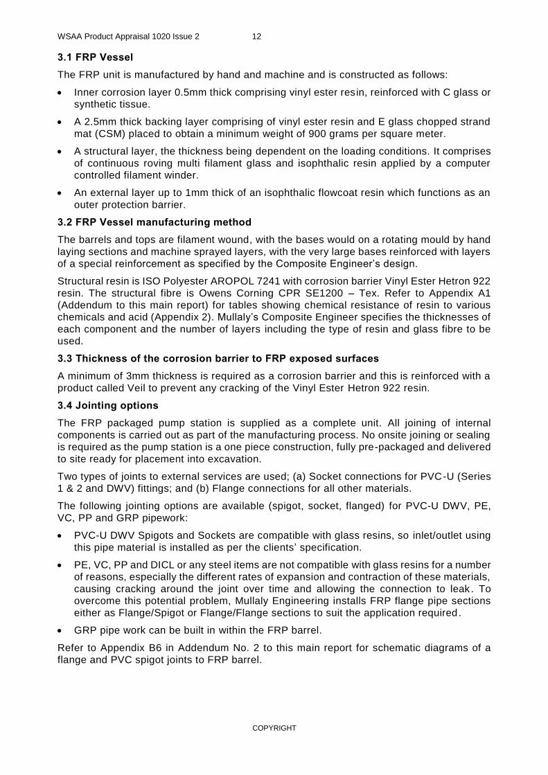
3.1 FRP Vessel
The FRP unit is manufactured by hand and machine and is constructed as follows:
Inner corrosion layer 0.5mm thick comprising vinyl ester resin, reinforced with C glass or
synthetic tissue.
A 2.5mm thick backing layer comprising of vinyl ester resin and E glass chopped strand
mat (CSM) placed to obtain a minimum weight of 900 grams per square meter.
A structural layer, the thickness being dependent on the loading conditions. It comprises
of continuous roving multi filament glass and isophthalic resin applied by a computer
controlled filament winder.
An external layer up to 1mm thick of an isophthalic flowcoat resin which functions as an
outer protection barrier.
3.2 FRP Vessel manufacturing method
The barrels and tops are filament wound, with the bases would on a rotating mould by hand
laying sections and machine sprayed layers, with the very large bases reinforced with layers
of a special reinforcement as specified by the Composite Engineer’s design.
Structural resin is ISO Polyester AROPOL 7241 with corrosion barrier Vinyl Ester Hetron 922
resin. The structural fibre is Owens Corning CPR SE1200 – Tex. Refer to Appendix A1
(Addendum to this main report) for tables showing chemical resistance of resin to various
chemicals and acid (Appendix 2). Mullaly’s Composite Engineer specifies the thicknesses of
each component and the number of layers including the type of resin and glass fibre to be
used.
3.3 Thickness of the corrosion barrier to FRP exposed surfaces
A minimum of 3mm thickness is required as a corrosion barrier and this is reinforced with a
product called Veil to prevent any cracking of the Vinyl Ester Hetron 922 resin.
3.4 Jointing options
The FRP packaged pump station is supplied as a complete unit. All joining of internal
components is carried out as part of the manufacturing process. No onsite joining or sealing
is required as the pump station is a one piece construction, fully pre-packaged and delivered
to site ready for placement into excavation.
Two types of joints to external services are used; (a) Socket connections for PVC-U (Series
1 & 2 and DWV) fittings; and (b) Flange connections for all other materials.
The following jointing options are available (spigot, socket, flanged) for PVC-U DWV, PE,
VC, PP and GRP pipework:
PVC-U DWV Spigots and Sockets are compatible with glass resins, so inlet/outlet using
this pipe material is installed as per the clients’ specification.
PE, VC, PP and DICL or any steel items are not compatible with glass resins for a number
of reasons, especially the different rates of expansion and contraction of these materials,
causing cracking around the joint over time and allowing the connection to leak . To
overcome this potential problem, Mullaly Engineering installs FRP flange pipe sections
either as Flange/Spigot or Flange/Flange sections to suit the application required.
GRP pipe work can be built in within the FRP barrel.
Refer to Appendix B6 in Addendum No. 2 to this main report for schematic diagrams of a
flange and PVC spigot joints to FRP barrel.
WSAA Product Appraisal 1020 Issue 2 13
COPYRIGHT
3.5 Access Covers and safety grates
Mullaly Engineering standard covers are hinged 6 mm aluminium checker plate Grade 5251
to AS 1743 that are light to lift and cannot fall into the wet-well or valve pit.
The covers can be padlocked shut and fitted with an optional step down aluminium safety
grates to allow inspection and hose down or even float switch replacement without risk to
service personnel.
The covers are sized to suit the pump and valve access requirements and the hinge
assemblies and step down.
The access covers and safety grates shall comply with specific requirements of some water
agencies to be allowed for use in their licensed area such as City West Water (CWW)
Supplementary Manual to the WSAA Sewerage Pumping Station Code (WSA 04-2005:2.1),
Version 2.4
4 SCOPE OF THE APPRAISAL
The scope of this appraisal is limited to the range of Mullaly FRP Packaged Pumping Stations
and Emergency Storage Tanks referenced in Section 3, valve chamber and covers. The
range of optional accessories (fit-out) are discussed in Clause 6.2.5 and 13 to demonstrate
product versatility but not intended to be included in the appraisal as they are usually
supplied to individual agency specification.
Mullaly Engineering offers an extensive range of optional accessories, offered at fit -out. The
extensive range of optional accessories includes mechanical, electrical and SCADA
equipment which can initially be reviewed by individual water agency on a case by case
basis. These options are not included in this assessment.
This appraisal covers FRP pump station and emergency storage tank packages used in
alternative water supply (storm water) and pressure sewer appl ications. Only the wet well,
valve chamber and access covers are being assessed.
5 APPRAISAL CRITERIA
Appraisal criteria is determined by the WSAA Infrastructure Products and Materials Network
and regularly reviewed to ensure that the criteria reflect the requirements of WSAA members.
The FRP pump station and emergency storage tank have been assessed in line with WSA
129:2011 Industry Standard for Plastics Collection Tanks for Pressure and Vacuum Sewers
which is based on AS 2634:1983.
5.1 Quality Assurance Requirements
The WSAA Infrastructure Product and Materials Network accept FRP components
manufactured and supplied under cover of a certified ISO 9001 management system. The
scope of the certification shall include “Manufacture and supply of FRP to AS 2634:1983 (or
similar).
5.2 Performance Requirements
5.2.1 Product Manufacturing Standards
There is no specific Australian or International product standard that provides manufacturers,
designers and installers with a document that outlines the specific criteria for the
manufacture of FRP chambers for sewerage applications, applicable to the scope of
products covered by this appraisal.
WSA 129:2011 is a WSAA Industry Standard that specifies the design, manufacturing and
performance requirements for manufacturers of plastics collection tanks for storage of
sewage in pressure and vacuum sewerage systems and which are specifically designed for
buried installation. This standard specifies performance requirements for Glass Fibre-
Reinforced Plastics as the material for collection tank.

WSAA Product Appraisal 1020 Issue 2 14
COPYRIGHT
Until such time as an appropriate Industry Standard, Australian or International Standard is
developed which specifies the
requirements of FRP chambers;
the minimum requirements for the materials to be used in, and the manufacture of; and
controlled quality FRP chambers components; and
includes descriptions of methods of sampling and testing of components.
The performance criteria defined in Sections 5.2.1, 5.2.2, 5.2.3, 6.2, 7.1, 7.2.1, 7.2.2, 8.1,
8.2, 9.1.2, 9.1.3, 9.1.4, 9.2.1, 9.2.2, 10.1.1, 10.1.2, 10.1.3, 10.1.4, 10.1.5, 10.1.6, 10.2.1,
10.2.2, 10.2.3 and 11 of WSA 129 shall be applied, noting that FRP chamber/vessel being
assessed is not a pressure vessel (i.e. pressure or vacuum sewer).
The FRP vessels are also designed to meet the requirements of AS 2634:1983 and BS
4994:1997.
The following Product Specification is also relevant to this application:
WSA 402 - Collection Tanks for Pressure and Vacuum Sewerage
A copy of the above Product Specification can be found in Appendix F or downloaded from
the WSAA website.
A geotechnical report prepared with information determined from soil samples taken at the
Pumping Station site, is requested by Mullaly Engineering in order to verify the structural
integrity of the design of the FRP Pumping Stations. As a minimum the geotechnical report
shall contain soil classification, information on the water table location, the soil bearing
capacity and the lateral earth pressure coefficients.
6 COMPLIANCE WITH APPRAISAL CRITERIA
6.1 Compliance with Quality Assurance Requirements
6.1.1 FRP Vessel supplier
Tank Solutions manufactures the FRP vessels for the Mullaly range of FRP Pumping
Stations and Emergency Storage Tanks.
Tank Solutions has third party accreditation to ISO 9001:2008 (SAI Global Certificate No.
QEC24768) for the manufacture of steel and fibreglass storage tanks for the chemical, fuel
and water industries.
6.1.2 Suppliers for Wet-well and valve pit access covers
Mullaly Engineering supply multi-part solid-top or recessed (with concrete infill) cast ductile
iron access covers and frames Class B, D or G for their range of FRP Pumping Stations and
Emergency Storage Tanks. Mullaly purchases these covers and frames from accredited
suppliers whose products comply with AS 3996:2006 Access covers and grates and/or WSA
132 Industry Standard for Ductile Iron Access Covers for water supply and sewerage.
In trafficable area, Class D covers and frames shall be provided to access points. In non-
trafficable areas, Class B access covers hinged to frames can be provided to access points.
In heavy duty areas such as Airport taxiways and Aircraft standing areas Class G can be
provided to access points.
Mullaly Engineering also offers marine grade aluminium access covers and safety grills as
fall protection as per the requirements of water company or local council. Mullaly
Engineering’s metal work fabricator has confirmed that these aluminium access hatch covers
and safety grills are fabricated by qualified welder tradesman, the majority of who have X-
ray welding certificates and are supervised by a workshop foreman with these certificates.

WSAA Product Appraisal 1020 Issue 2 15
COPYRIGHT
The aluminium access hatch manufacturer has also confirmed that either he and/or his
workshop supervisor carry out the welding and aluminium fabrication inspections in
compliance with AS 1664:1979 Rules for the use of aluminium in structures.
The aluminium access covers for the wet-well and/or valve pit are designed and fabricated
using aluminium commercial grade 5052 in H32 temper with tr iple grip finish.
Mullaly Engineering supply lockable aluminium hinged lids, including the galvanised swing
up safety grate. The cover is manufactured from 6 mm checker plate using aluminium
commercial grade 5052 in H32 temper with triple grip finish with recessed hinges and lifting
handles. Hinged safety grates are mounted below the cover to prevent operators accidentally
falling into the wet-well. The individual covers are opened only during pump removal. The
covers are sized to suit the pump and valve access requirements and the hinge assemblies
and step down frame is cast into the cover slab.
Mullaly Engineering assembles an EPDM rubber odour seal to the frame edging under the
cover. Mullaly Engineering advises that their aluminium covers are water and gas tight. The
use of the foam seal and the locking system sizing to suit the size of the padlocks used by
the various Water Authorities is designed to press the aluminium access hatch covers down
and compress the foam to give a water and gas tight seal.
The cover slab is set above ground level if rainwater surface infiltration is likely. The height
of the cover slab above ground level is specified on the Project Drawings to conform to the
Water Agency requirements.
Mullaly Engineering have indicated that aluminium post inserts for corner posts for rail safe
telescopic guardrail system can be cast into the cover slab or mounted underneath the cover.
Mullaly Engineering aluminium covers, when subjected to centrally placed load of 120 kg,
did not exceed the 20 mm deflection of the cover, as specified in Clause 5.8 of the Sewage
Pumping Station Code of Australia, WSA 04:2005.
Mullaly Engineering safety grates can be made to order with a suitably located lockable
access point and cover of minimum size 300 mm x 300 mm to allow easy access for
maintenance of all level sensing equipment. Safety grates are provided as standard on all
Mullaly Engineering FRP pump stations and emergency storage tanks.
The aluminium cover design allows the cover to be opened fully and laid flat.
Mullaly Engineering recommends safety grates as fall protection measure for valve pit depths
greater than 1.5 m.
Mullaly Engineering has advised that in line with current trends, pumping stations are rarely
located in trafficable areas and ductile iron covers are therefore not normally fitted. Mullaly
Engineering advises that some ductile iron covers exceed OH&S maximum lifting limits and
pose other safety risks to service personnel.
6.2 Compliance with Performance Requirements
Mullaly Engineering manufactures solid FRP wall pump stations, not requiring attachment of
external strengthen ribs. The design thickness and manufacture methodology is supplied by
an independent third party Composite Engineer.
The FRP vessels are designed to meet the requirements of:
AS 2634:1983 Chemical Plant Equipment made from Glass-Fibre Reinforced Plastics
(GRP) based on thermosetting resins; and
BS 4994:1997 Specification for design and construction of vessels and tanks in
Reinforced Plastic
Mullaly Engineering's designs, manufacturing process and products are certified by an
independent composite engineering organisation (Oceania Composite Engineering Pty Ltd)

WSAA Product Appraisal 1020 Issue 2 16
COPYRIGHT
whose Principal is a Chartered Professional Engineer (CPEng Membership No: 2696347) of
Engineers Australia and Registered Professional Engineer of Queensland (RPEQ,
Registration No. 9566)
Mullaly Engineering performs the following quality tests to ensure the FRP vessels are
constructed in line with AS 2634:
a) An independent third party Composite Engineer performs periodic visual inspections of
completed FRP vessels. Refer to Appendix C for a copy of the inspection report.
b) The independent third party registered Composite Engineer also provides a verification
statement for each completed FRP vessel based on a review of working drawings, the
finished product inspection and drawings of the finalised specifications. Refer to
Appendix C for a copy of the design verification statement. The design verification
statement covers:
Performance against design
Structural conformity to design
Compliance with AS 2634:1983 as it applies to Mullaly Engineering specification
MESPEC01 Standard Specification for FRP Units in use for Packaged Pump
Stations
Fitness for purpose
c) At completion of each FRP vessel, a quality inspection is performed by Mullaly
Engineering’s in-house Engineer using a quality checklist that ensures the vessel meets
all required design standards.
d) The University of Southern Queensland (USQ) performs periodic burnout tests of
samples from the FRP vessel to ensure the “resin to fibre percentage” complies with AS
2634. Refer to Appendix B7 in Addendum No. 2 for copy of the burnout test results from
a sample taken from the Sydney Airport Pier B FRP pump station wet well wall.
e) Pressure tests are performed on the internal pipe work and fittings of each completed
station.
f) Mullaly Engineering conducts ‘type tests’ as per Clause 10.1 of WSA 129 as detailed in
Table 4.

WSAA Product Appraisal 1020 Issue 2 17
COPYRIGHT
6.2.1 FRP Material Components
The FRP vessels have been assessed in line with WSA 129:2011 Industry Standard for
Plastics Collection Tanks for Pressure and Vacuum Sewers which is based on AS
2634:1983. Refer to Table 3.
TABLE 3: FRP MATERIAL COMPONENTS
WSA 129 Clauses for Material Components
Mullaly’s Response on their FRP Vessel Remarks
5.2.1 - Resin (Glass Fibre Reinforced Plastics)
An ISO-polyester resin (Aropol 7241) is used for the structural layers of the tank, whilst a Vinyl Ester resin (Hetron 922) is used for the Corrosion Barrier (refer 5.2.3).
The ISO resin used is as follows:
Barcol Hardness: 40
Tensile Strength MPa: 63
Elongation at Break: 2.5%
Flexural Strength MPa: 163
Flexural Modulus GPa: 3.9
Heat Distortion temp @ 1.82 MPa (°C): 100
Given the fact that new resins are constantly being developed, it is possible that a different material with superior specifications may be adopted in the future.
Comply
5.2.2 Reinforcement (Glass Fibre Reinforcement)
The reinforcing material shall be a suitable grade of glass fibre having a glass finish compatible with the resin used and complying with BS 3396 Part 3, EN 14118-1, 2 and 3 or BS 3749, as appropriate.
Comply
5.2.3 Resin coatings (Polyester and vinyl ester)
A Corrosion Barrier as per BS 4994 (Category II and III), consisting of a resin rich surface layer reinforced with C-glass surfacing mat, synthetic fibre or other suitable material with a backing layer consisting of two layers of 0.45kg/m² CSM with between 27% - 33% glass content by mass (Section 7 of BS 4994). In addition, the outermost layer of the stations consist of a minimum of 0.45kg/m² CSM and tissue with resin rich surface (as per Note in Section 13.4 of BS 4994).
Comply
5.2.3.3 Resistance to strain corrosion
This is not done. The manufacturer’s specified service conditions are used to determine the limits of applicability of the resin. A lot of strain testing has been done historically by the resin companies. As the designs are not strength limited, the strain issue is unlikely to be a problem.
Acceptable
6.2 GRP Plastics Tanks The design of glass fibre-reinforced plastic tanks shall be in accordance with BS 4994.
Comply
6.2.2 Type Tests
Mullaly Engineering FRP vessel complies with most of the type tests of Clause 10.1, WSA
129 as detailed in Table 4:
TABLE 4: TYPE TESTS
WSA 129 Clauses for Type Tests
Mullaly Response Remarks
10.1.1 General
All tanks shall comply with the type test requirements of Clauses 10.1.2 to 10.1.5 inclusive. These tests may be combined by applying the lateral and top loads to a tank before conducting the water tightness test. In addition, glass fibre-reinforced plastics tanks shall comply with Clause 10.1.6.
Mullaly Response: The testing performed on Mullaly FRP products includes the following:
Barcol Hardness (see Section 10.1.6.4 below), Thickness, Dimensional checks and Pressure Test on Pipework.
Thickness - Thickness of the tank itself, as well as all FRP component parts are
measured to ensure minimum design criteria have been met.
Dimensions Checks - Checks of all component parts are conducted at various
stages of production to ensure all components are within tolerance.
Pipework Test - Whilst the tank itself is not tested (see below) the internal
pipework is tested, by sealing all pipework connections, then applying a 3psi positive pressure. All connections are then soap tested to ensure pipework is airtight.
Comply

WSAA Product Appraisal 1020 Issue 2 18
COPYRIGHT
WSA 129 Clauses for Type Tests
Mullaly Response Remarks
10.1.2 Water tightness
When an assembled tank including access openings and covers, inlet fittings and outlet fittings is tested in accordance with the hydrostatic pressure test of AS/NZS 1462.10, at an internal pressure of 85 +5, −0 kPa for 60 +5, −0 min., the assembled tank shall not leak.
Mullaly Response: Water tightness tests are not carried out on every station, due
to the amount of water being lost once this test is complete, we periodically seal the penetrations with blank flanges and standard drainage test plugs and an FRP flat section with a gasket to seal the access opening and a pressure gauge to record any loss of pressure.
This pressure is normally maintained for one hour during which time soap tests are applied to each of the penetrations to visually see if any leak occurs.
Mullaly also test the FRP Flange/Flange connections through the wet well to valve chamber walls, on stations requiring pressure test points installed. The test pressure is raised to 150% of the installed pipe and valve rating, all test to date have proved positive.
Mullaly have attend a large number of site installation full water tests as per the requirement by most Water Authorities. These installations include stations installed by Mullaly construction company and private contractors in QLD and NSW. None of these vessels have failed the water tightness test; all have had no loss of water recorded.
Acceptable
10.1.3 Liquid infiltration test
When an assembled tank including access openings and covers, inlet fittings and outlet fittings is tested in accordance with AS/NZS 1462.8, is subjected to an internal vacuum or external hydrostatic pressure, resulting in a pressure differential of 80 +5, −0 kPa, for 60 +5, −0 min, the assembled tank shall not leak.
Mullaly Response: These vessels are designed and constructed to meet the
applicable requirements of BS4994 and historically there is sufficient evidence to show that BS4994 constructed vessels do not permit infiltration therefore the liquid infiltration test is not required
Acceptable
10.1.4 Resistance to lateral loads
When tested in accordance with EN 1277 Condition A for 100 h at 23±2°C with an internal negative pressure of 300 +5, −0 kPa, the assembled tank shall not suffer any damage to its structure that could be deemed to impair its function. Following the application of lateral loads, each tank shall pass the water tightness test in accordance with Clause 10.1.2.
Mullaly Response: Not required due to the vessels being designed to withstand full ground pressure with a safety factor added.
Although Mullaly does not comply, their justification is acceptable
10.1.5 Resistance to top load
Following the application of a top load in accordance with Appendix G of AS/NZS 1546.1:2008, each tank shall pass the water tightness test in accordance with Clause 10.1.2.
Mullaly Response: Our FRP vessels are designed to carry a temporary installation
load after which the vessel roof is protected by the concrete slab and any external loads are either on the cover or directed through the wall of the station.
Comply
10.1.6 Glass fibre-reinforced plastics tanks
10.1.6.1 Test specimens
All test specimens shall be prepared in accordance with ISO 1268-1. Informative
10.1.6.2 Flexural strength and modulus of elasticity
When tested in accordance with ISO 178, the flexural strength and modulus of elasticity of each test specimen shall be not less than 110 MPa and 4830 MPa, respectively.
Mullaly Response: Mullaly’s Composite Engineer has advised that the design
criteria he requires us to manufacture these FRP vessels with the resin to fibre percentages required being confirmed by the ‘Burnout tests’ indicates a strength and modulus of electricity much greater than the indicated test requirement.
Acceptable
10.1.6.3 Impact resistance
When tested in accordance with ISO 179-2, the test specimen shall have no surface cracks visible to normal or corrected normal vision.
Mullaly Response: Mullaly FRP vessels are manufactured to pass the BS4994
impact test specification and the manufacture and final inspections confirm there is
no surface crack visible prior to despatch.
Acceptable
10.1.6.4 Hardness When tested in accordance with Appendix J of AS/NZS 1546.1:2008, the Barcol hardness number of each test specimen and any part of each test rainwater tank shall be not less than 35.
Comply

WSAA Product Appraisal 1020 Issue 2 19
COPYRIGHT
Mullaly Response: The Barcol hardness number is not an arbitrary number and
depends on the resin used. The figure that is needed to be obtained should be in the order of 80% (or greater) of the manufacturer’s specified figure. All FRP vessels are checked to ensure they comply with this Clause.
10.1.6.5 Water absorption
When tested in accordance with ISO 62, the amount of water absorption of each test specimen shall be not greater than 0.75%.
Mullaly Response: Water absorption % in FRP manufactured vessels is
controlled by the quality of the resin and the percentage ratio between resin and fibre. The design of the Mullaly vessels guarantees a lower percentage of water
absorption than the 0.75% requirement for this test.
Acceptable
10.1.6.6 Glass fibre content
When tested in accordance with ISO 1172, the glass content of each test specimen shall be not less than 30% w/w. The test specimens shall be through-thickness to exclude the resin-rich internal layers being measured on their own.
Mullaly Response: In addition to this testing, a construction analysis is being
performed confirming the adequate quantity, type and orientation of the glass layers.
Comply
10.1.6.7 Tensile strength
When tested in accordance with ISO 527, the tensile strength shall not be less than 63 MPa.
Mullaly Response: The 63 MPa requirement shown for this test is a requirement
commonly used for CSM (Chopped Strand Mat) and is a very low figure, quality CSM manufacture should have > 90 MPa, the composite design of our vessels are manufactured for the use of continuous roving which will return a test result greater than the 110 MPa requirement of ISO 178, shown in point 10.1.6.2 above.
Acceptable
10.1.6.8 Tensile Elongation
When tested in accordance with ISO 527, the tensile elongation shall not be less than 1.5% minimum.
Mullaly Response: Tensile elongation is a function of the laminate itself and is a
function of the resin and fibre system employed. The design requirement we manufacture to links strength and modulus requirements to exceed the minimum elongation required for the service life of these vessels.
Acceptable
6.2.3 Batch Release Tests
TABLE 5: BATCH RELEASE TESTS
WSA 129 Clauses for Batch Release Tests
Mullaly Response Remarks
10.2.1 General
Each batch of tanks shall comply with the test requirements of Clauses 10.2.2 to 10.2.4 as appropriate before release.
Mullaly Response: Each FRP vessel is designed and manufactured to meet the
requirements of the client and their site. Therefore no batch testing is performed but each individual vessel is tested.
Justified
10.2.2 Vacuum test – all tank materials
When tested in accordance with Appendix B, a sample from each production batch of tanks, and for cast in-situ concrete tanks each tank, shall not leak, collapse, buckle or delaminate.
Mullaly Response: As per above reason, no batch testing is performed.
Justified
10.2.3 Glass fibre-reinforced plastics tanks
The following tests shall be conducted on each batch of tanks:
a) Thickness of laminate (Refer to #Clause 7.2.2 below). - Yes
b) Thickness of internal resin-rich layer at time of application (Refer to Clause 5.2.3). - Yes
c) Hardness (Refer to Clause 10.1.6.4). – See comment above
d) Reinforcing fibre content (Refer to Clause 10.1.6.6). – See comment above
Comply

WSAA Product Appraisal 1020 Issue 2 20
COPYRIGHT
WSA 129 Clauses for Batch Release Tests
Mullaly Response Remarks
11 Marking Mullaly FRP vessels are legibly and permanently marked on the tank wall or roof as follows:
Manufacturer’s name or registered trademark - Yes
Date (month and year) of manufacture - Yes
Material identification (FRP) - Yes
Useable volume in litres - Yes
Safe installation depth in metres - Yes
Number of this Standard (i.e. WSA 129:2011) - No
In addition, Mullaly include the below marking:
Unique identification number
Whether the station is ribbed or monolithic
Comply
6.2.4 Additional Assessments on FRP Vessel and Valve Pit
TABLE 6: ADDITIONAL ASSESSMENTS
WSA 129 Clauses Mullaly Response Remarks
Dimensions and Tolerances
7.1 Dimensions
All dimensions shall be taken at the time of manufacture with the tank in the operating upright position, unfilled. Tank dimensions shall represent the exterior measurements.
The dimensions (wall thickness, diameters, tapers, lengths and lengths of engagement) of tank components, including spigots and sockets for pipe connections, shall not be less than those specified in the relevant Australian Standard for a fitting or component of the same material and nominal diameter, e.g. AS/NZS 1260 for PVC-U.
Mullaly Response:
The tanks are measured in the horizontal plane, they are supported on purposed made rollers to allow us to turn them as required to check dimensions etc. There is a manufacture inspection and check prior to the joining of the base to the barrel plus a final inspection and check by the Manager of Mullaly Engineering, Paul (Mullaly’s in-house engineer) or a qualified independent inspector prior to dispatch to confirm all dimensions meet the design requirements.
All dimensions, thicknesses and fittings have to comply with Mullaly’s Composite Engineers design. Copies of the QA records have to be supplied on each station before he will issue a DVS Certificate for that station. In addition regular in production inspections by the Composite Engineer and burnout test results guarantees that the tank meets the design requirements, which comply with and exceed the relevant Australian and NZS standards.
Comply
7.2 Tolerances
7.2.1 Outside dimensions
The tolerance for outside dimensions, including out of roundness, shall be ±3% of the specified outside dimensions. The tolerances of dimensions (wall thickness, diameters, tapers, lengths and lengths of engagement) of tank components, including spigots and sockets for pipe connections, shall not be less than those specified in the relevant Australian Standard for a fitting or component of the same material and nominal diameter, e.g. AS/NZS 1260 for PVC-U.
Mullaly Response:
Our tank outside dimensions has to be less than + or – 0.005% to allow the barrel to fit into the recess on the base flange when being joined, this is critical to guarantee the tank will be straight and stand plumb when in the vertical plane for installation.
Due to our heavy wall thickness design the problem of out of roundness is not encountered.
Wall thickness, component diameters, spigots and sockets are all manufactured and installed to the Composite Engineers details. His designs meet and exceed the requirements of the relevant Australian and NZS standards. The Engineer is highly qualified with more than 10 years design and inspection experience with these tanks.
Comply

WSAA Product Appraisal 1020 Issue 2 21
COPYRIGHT
WSA 129 Clauses Mullaly Response Remarks
7.2.2 Tank wall and roof thickness
Wall and roof thickness shall be the design thickness −10%, +unlimited. The total amount of surface area with a thickness below the design thickness shall not exceed 10% of the total surface area, and an individual area shall not exceed 0.10 m2. Where wall and roof thicknesses are measured using ultrasonic equipment, this equipment shall be capable of measuring to an accuracy of 0.1 mm.
Mullaly Response:
Roof and wall thickness are manufactured to meet and exceed the design thickness from our Composite Engineer.
If excessive loads are to be applied due to site conditions we are advised of, the Engineer designs the thickness and reinforcement materials required to meet these loads. Large roof areas subject to heavy loads are carefully checked to allow for the live loads encountered during placement and finishing of the concrete roof slabs.
Comply
8 FITTINGS
8.1 General The suitability of fabricated fittings, gaskets and other fitting accessories intended for use in tanks shall be based on product data, or advice obtained from the fitting supplier.
Fittings shall be compatible with the tank and catchment system materials.
Mullaly Response:
All fabricated fittings etc. are installed to meet the client’s specification for that station. Fibreglass flanged connections are built into the tanks to allow for connection by non-compatible materials such as PE or metal pipes. A FRP flange complying with AS 2129 drilled to the requested drill pattern, normally Table D or E is installed to allow this material to be connected to the tank.
Comply
8.2 Fittings and Flanges
Inlet and outlet fittings may be installed either by the manufacturer prior to delivery of the tank or by the constructor at the time of installation of the tank. Flanges and fittings integral to the tank shall make a leak proof seal with the tank. Threads shall not be tapped directly into the tank wall unless the thread depth is greater than or equal to the relevant fitting spigot thread length. Threaded sockets formed in the tank wall during the moulding process shall be acceptable. Where required, connecting flanges should comply with AS 4087 and connecting threads should comply with AS 1722.1 or AS 1722.2.
NOTE: Threads on connecting fittings are often made undersize to ensure they fit a wide range of products with nominally similar threads. A check should be made of the fastening and sealing capability of the tank connecting thread with the fitting intended to connect to it.
Mullaly Response:
All inlet or outlet connections through our fibreglass structures must be installed in our factory under supervision. Mullaly refuse to supply tanks for a third party to fit out by cutting and drilling holes in the fibreglass structure. Every cut out or drill hole requires preparation and sealing with Vinyl Ester resin as a corrosion barrier, prior to the installation of FRP or compatible UPVC connections. Plus requires preparation of the fitting prior to installation and with a minimum of 100mm exposed each side of the FRP to meet the bonding design detail procedure for their installation.
No threads or tapping of the FRP sections are allowed in our design. Complying connection fittings can be installed to allow for threaded fittings to be connected.
Comply
9 MANUFACTURE
9.1.1 Surface finish: For glass fibre-reinforced plastics, acceptance of surface defects shall be in accordance with Appendix ZC of AS 3571.1:2009.
Figure 1 shows the internal surface of Mullaly FRP vessel (new and after 5 years), which demonstrates compliance to Clause 9.1.1
Comply

WSAA Product Appraisal 1020 Issue 2 22
COPYRIGHT
FIGURE 1: INTERIOR SURFACE FINISH – NEW AND AFTER FIVE YEARS IN
SERVICE
WSA 129 Clauses Mullaly Response Remarks
9.1.2 Colour Tanks if manufactured in layers shall have their surfaces coloured throughout. The internal surfaces of tanks shall be a light colour to permit condition assessment of the tank by CCTV inspection.
Mullaly Response:
All tanks are manufactured with computer controlled equipment which is a continuous process, with the filament winder equipment only stopping if the computer closes it down due to a rise in temperature of the barrel being wound, reaching 10% below the temperature where the fibreglass could start to create bubbles. To counter this, most barrels are wound on our evening shift, of when required an early morning before daylight shift.
The internal surface has to be left clear so our inspections will show any faults if they arise.
Comply
9.1.3 Assemblies Components of tank assemblies can be a combination of two or more of the specified materials, which may also be used for different components of the same fitting.
Mullaly Response:
All components of our tanks are the manufactured from the same resins and glass fibre to meet our Engineers design. The design of a 3750mm diameter x 9m deep tank currently being manufactured requires the installation of two separate layers of a 25mm thick fibreglass mesh reinforcing material to strengthen the base and roof to counter the loads that this station will be subject to.
This fibreglass reinforcement is a relative new product that our Engineer has had thoroughly tested over the last two years and is now confident this material will increase the strength of our tanks etc. to a greater degree, than increasing the wall thickness to meet the pressure loading required.
Comply
9.1.4 Inlet and outlet holes
Tank fittings inlet and outlet holes shall be cut or formed in the tank wall prior to the tank leaving the manufacturer’s premises. Tank fittings inlet and outlet holes ends shall be cleanly cut and square with the axis of the ends and within any cutting zone provided by the design.
Mullaly Response:
As described in Clause 8.2 all inlet and outlet holes are cut and treated prior to the installation of the fitting being installed. The fitting is installed using a jig to hold the fitting square to the installed location, this guarantee the flange faces will be in line to meet the connection flange without pressure being applied to make the joint fit correctly.
No tank will be allowed to leave the factory requiring any cutting or drilling on site or at another location. There have been occasions where additional fittings have been required while the tank is being installed. In these cases a detailed installation procedure is provided and either one of our staff or a known qualified fibreglass operator is employed to carry out the new installation under the supervision of one of our staff or our agents.
Comply

WSAA Product Appraisal 1020 Issue 2 23
COPYRIGHT

WSAA Product Appraisal 1020 Issue 2 24
COPYRIGHT
WSA 129 Clauses Mullaly Response Remarks
9.2 GLASS FIBRE REINFORCED PLASTICS TANKS
9.2.1 General The method for the manufacture of components for glass fibre-reinforced plastics tanks shall be by:
(a) The even application of resin and glass to the mould;
(b) Rolling the lay-up to achieve:
(i) Complete wetting of the fibres;
(ii) Removal of air bubbles and voids throughout the thickness of the laminate; and
(c) Rounding of all internal corners with a radius of not less than 6 mm;
The mass of glass rovings, if filament winding is used, shall be determined continuously as the material is applied.
Mullaly Response:
(a) The design of our filament winder allows an even application of resin and glass fibre. The fibres pass through ceramic bobbins built into a frame at specific centres to meet the design requirements and pass through a resin bath at the correct rate to pick up the required volume to be applied onto the winder. An operator is employed to constantly monitor this process to make sure that the materials are being processed correctly.
(b) Hands laid materials are carried out by trained operators under supervision of a floor manager to make sure (i) & (ii) are carried out correctly.
(c) The manufacture design of these tanks will not allow radius less then 20mm. (d) The mass of glass rovings applied by our filament winder is controlled as
described in item (a).
Comply
9.2.2 Laminate and thickness
The composition and thickness of the laminate shall be as follows:
(a) Tank
The laminate shall contain not less than 30% glass. No pigments shall be included in the laminate. The thickness of the laminate shall be not less than 4 mm. The thickness shall be increased to be not less than 6 mm for a distance of not less than 40 mm from all edges of openings and the edges of up stands for access and inspection covers. Changes in thickness shall be by smooth transitions. The external surface of the tanks shall be coated with either a clear layer of initiated (catalysed) resin or an external flowcoat as defined in Clause 5.2.3.1(b), of not less than 0.4 mm thick.
(b) Access opening cover and top of vertical tanks
Access, inspection covers and tops of tanks shall contain not less than 30% chopped glass strands. The thickness of the laminate shall be not less than 4 mm. This shall be increased to 6 mm within 40 mm of any edge.
Mullaly Response:
Mullaly’s Composite Engineers tank, base, roof and valve pit design meets and exceed the relevant Australian and NZS standards, so Mullaly’s laminate will contain greater than 30% of glass fibre.
The tanks are manufactured using a solid wall design where even on a small diameter tank the wall thickness will be greater than 20mm.
Mullaly believe thin wall tanks should only be installed in above ground applications where they can by visually monitored and repaired if cracking occurs.
Flow coat material approximately 1.5mm thick is applied to the external surface of the tanks, to give added protection to the external corrosion barrier during transport and installation.
The access opening are manufactured to meet the Engineers design as above, with the neck riser finished with a fibreglass flange section to strengthen this area and allow the selected access hatch cover to be fitted.
Tops of tanks are manufactured as detailed in the answer to clause 9.1.3 above.
Comply
6.2.5 FRP Packaged Pump Station – Buoyancy Consideration
Mullaly Engineering has submitted guideline/parameters for ballast calculations to prevent
hydrostatic uplift of FRP vessel.
Refer to Appendix E for a sample of Ballast Calculation with two schematic diagrams
providing guidance to the Installers on (a) Station Parameters (b) Concrete Ballasts (c)

WSAA Product Appraisal 1020 Issue 2 25
COPYRIGHT
Backfill Ballasts and (d) Roof Slab. These guidelines are site specific and are provided with
each pump station.
Mullaly’s calculations have been checked and approved by Consulting Engineering
companies such as GHD, SKM, AECOM, Cardno, Arup and Aurecon Australia as well as a
number of smaller Consultants.
All underground structures are potentially subject to hydrostatic loading from ground water
should it be present. Where this loading is greater than the self-weight of the structure it is
possible the structure could move due to buoyancy forces. There are numerous ways the
potential movement due to buoyancy can be eliminated. These include:
Placement of backfill material either concrete, soil or a combination of both over or
around the structure to act as ballast against the uplift forces;
Anchoring the structure to concrete deadman, hold-down slabs or surrounding strata
should suitable material, such as high strength rock , be present;
Increasing the dead weight of the structure; and/or
Decrease the hydrostatic loading by either removing or lowering the level of ground water
around the structure.
For its Packages Pump Station and Emergency Storage Tank, Mullaly Engineering
recommends the ballasting method to resist buoyancy forces. As part of the installation
instructions provided with each station, a recommendation is included of the ballast required
for its safe installation. In determining the ballast required for a FRP Packaged Pump Station
or Emergency Storage Tank, a worst case scenario is considered based on the following
conditions:
The surrounding soil is completely saturated to the surface level resulting in hydrostatic
loading of the station for its full depth;
In determining the self-weight of the station, it is assumed any removable equipment
including the pumps are not in place;
The station is completely empty with no water/ sewage present to provide downward
loading;
Backfill materials are cohesionless with no soil friction present; and
Weight of ballast material is adjusted to take into account the hydrostatic loading on it.
The ballast calculations are based on parameters as detailed in Table 5:
TABLE 7: PARAMETERS FOR BALLAST CALCULATIONS
Parameter Value
Weight of water 9.8 kN/m3
Weight of ballast concrete
Nett ballast loading
23.5 kN/m3
13.7 kN/m3
Weight of soil backfill
Nett ballast loading
17.6 kN/m3
7.8 kN/m3
Factor of Safety for
a) up thrust due to buoyant forces
b) resisting force due to dead weight of precast components (base + increments + cover) against potential uplift
1.10
0.90

WSAA Product Appraisal 1020 Issue 2 26
COPYRIGHT
6.2.5.1 Ballast Layout
The nett weight of the ballast material is to be greater than the buoyancy forces on the
structure less its dead weight plus the required Factor of Safety.
The FRP packaged pump station is manufactured with an external hold down flange/s or
ribs, onto which a concrete ballast slab is poured. The shape of the slab is either round or
square, the selection of which is dependent on the size of the station and the surrounding
conditions. The minimum depth of this slab is sufficient for the transfer of ballast loading to
the hold down flange without the need for reinforcing steel. The overall depth of the concrete
slab is dependent on the ballast loading required.
Above the ballast slab, compact fill is placed. The weight of material directly above the
concrete slab is only considered for ballast calculation purposes.
Concrete roof slabs are recommended for all stations and the weight of these are included
in the ballast calculations.
For shallow FRP structures such as standard alone Valve Pits, the weight of the roof slab
generally provides sufficient ballast loading. Where additional ballast is required, thickened
edge beams to the roof slab are recommended.
Refer to Q&A No. 1 in Section 7 for further information on Ballast calculations performed by
Mullaly Engineering.
6.2.6 Attachments
Mullaly Engineering design, manufactures and supplies either own stainless steel (SS) 316
ladders and brackets. Other attachments such as platforms, handrails or fiber reinforced
plastic ladders can be fitted to suit Water Agency Specifications.
NOTE: The above items are not included in this appraisal.
6.2.7 Review of the documentation and guidance for designers, installers and
operatives
Mullaly Engineering provides customers with documents for submission of their pump station
requirements, plus diagrams for customers/designers to nominate pipe positions for factory
cored apertures. Also provided to customers is a list of items required to be completed prior
to installation and/or commissioning of the pump station.
For further information refer to Section 8.
7 WSAA NETWORK REQUESTS
Question 1: Concerns have been raised about resistance to flotation when installed in water
charged ground. How do you address this buoyancy issue in the design calculation? Do you
assume the groundwater level to exist at the surface of the pumping station as a worst case
scenario? To provide additional resistance to buoyant forces, do you provide a concrete ring
beam cast in situ in the base configuration? Do you undertake any additional precautions
against flotation by increasing weight of precast concrete cover slab by increasing its
thickness?
Answer 1: Our in-house engineer has a Masters of Engineering degree and has been in
this industry over 25 years He does the ballast calculations for each of the pump station
sizes we manufacture which are based on the ground being 100% saturated and with a
further 10% added as a safety margin.
Our calculations have been checked by ARUP, Aurecon, AECOM, Sinclair Knight Merz,
GH&D and CARDNO consulting engineers on various projects and these consultants have
approved the calculations as submitted. If there is a special circumstance such as the station
installed in Sydney Harbour at the Darling Park project, where the pump station is 90%
submerged in the Harbour, we meet this situation with a special FRP flange built onto the
WSAA Product Appraisal 1020 Issue 2 27
COPYRIGHT
external diameter of the station at 800mm below the finished level, allowing a concrete beam
to be cast as part of the concrete walkway structure, to encase this FRP flange and prevent
hydraulic uplift from the tidal changes each day.
Question 2: The Mullaly packaged pumping station is a turn-key product. The civil
contractor's main responsibilities are installation of FRP wet wells and valve pits, excavation,
trenching and backfill works, water supply and site restoration.
The turn-key scope of works also includes the mechanical and electrical fit -out and overall
supervision of the project from geotechnical testing of site, material delivery, attending site
during installation, testing, commissioning and hand over.
Which parts of the above package does Mullaly take responsibility for? How long the
packaged FRP pump stations are warranted from the date of installation and who provides
such warranty?
Answer 2: The major number of FRP station we manufacture, meets a design supplied by a
registered consultant or an in house design from authorities such as City West Water
Melbourne. We often have to modify these designs to suit FRP, as they are supplied as
either precast or in situ concrete designs. In these cases, Mullaly’s in-house engineer
redraws the station in FRP, then the revised drawings are forwarded to both an independent
third party Composite Engineer and our client for approval and for any modification required,
before we proceed with manufacture.
We are responsible for the design of the fiberglass structure which is supplied to us by an
independent third party Composite Engineering firm. The FRP design guarantee’s a 50 years
working life before any deterioration starts. We expect our stations to have a 100 or more
year life before replacement or modification is required.
For the design of pumps to suit the duties required, we contact the specified manufacturer
with the details and request them to advise as to most suitable pumps.
As the electrical control equipment and enclosure requirements are so varied between water
and waste water authorities, we will only price the supply of these fit-outs if we receive a full
set of electrical drawings and specification outlining the clients’ requirements. We do receive
requests for this supply and often do, but only to meet the design supplied.
We offer supervision of the pump station installation as an extra item if required. This is a
request we receive and have done on a number of occasions, especially in difficult locations
or where the end client is unsure of the experience of the contractor doing the installation.
We also offer to do the installation either as only the FRP packaged pump station and or
emergency storage tank, or as the total contract. But due to cost implication, we normally
undertake such installation in NSW or in an area approximately 300km from Sydney.
We have been contracted to do full installations as far away as Cairns in North Queensland.
In this installation we trained a local contractor while carrying out the installation with our
staff and now he became as the major installer in that area, currently engaged in a four year
Cairns Regional Council and GH&D Consulting Engineers contract for the upgrade and
installation of sewer pump stations.
One of our qualified staff or agents, if requested will attend the testing and commissioning
of one of our pump stations. PPS our Townsville agent attends every pump station testing
and commissioning in North Queensland.
Question 3: How many FRP packaged pumping stations and emergency storage tanks have
Mullaly supplied? Please provide a list in a tabular form indicating details of those pump
stations (dia & depth) and customers.
Answer 3: In excess of 300 FRP Pump Station projects have been completed at various
locations throughout Australia since late 1992. Some of these projects have had more than
one station, with a couple having up to eight stations for a single project.

WSAA Product Appraisal 1020 Issue 2 28
COPYRIGHT
A total of nine FRP Emergency Storage Tanks have been supplied.
Refer to Section 12 for details.
Question 4: Is it possible for liquid to leak out of the pumping station or for groundwater to
ingress?
Answer 4: No, our FRP pump stations are designed and manufactured as a fully sealed unit.
FRP Flange/Flange or Flange/Spigot connections are installed to suit the required external
pipe materials, to prevent non-compatible material expansion and or contraction occurring
and causing cracking around the connection which will allow leakage occurring.
The exception is the installation of white PVC connections, either DWV or Pressure pipe,
these materials are compatible with FRP, so can be installed into the wall or roof of the pump
station. We have design details and procedures for these installations. I have attached
copies of typical installation design drawings (shown in Appendix A6 in Addendum No. 1).
The station previously listed (in Answer 1) has been partly submerged in Sydney Harbour
for a number of years. Another station in Darwin Harbour exposed at low tide and about 90%
submerged at high tide, it has been there since about 1995. Neither of these stations have
ever had any leaking problems.
Question 5: Does the aluminum plate used to fabricate the access covers and frames for
wet-well and valve pit comply with AS 1734 Grade 5052 and is the design and fabrication in
accordance with AS 1664? Do you consider alternative aluminum grade such as 6061 T6
and or Grade 5083 H116 to AS 1734.
Answer 5: Our Access Hatch Cover Manufacturer has advised that (a) the class of
Aluminium used is 6060 grade for the angle frames; (b) marine grade 5052 for the 6mm thick
chequered plate covers; and (c) the design and fabrication of these units is in accordance
with AS 1664.
The alternate aluminum grades mentioned should be able to be fabricated. We supply
different grades of aluminum grating as safety grills to meet different water authority’s
specifications, so I don’t envisage a problem with different grades of aluminum materials.
Question 6: Does the welding and inspection of the above aluminium fabrication comply
with the requirements of AS 1664?
Answer 6: Yes, I have discussed with our metal work fabricator and have been advised that
all our access hatch covers and safety grills are fabricated by qualified welder tradesman,
the majority of who have X-ray welding certificates and are supervised by a workshop
foreman with these certificates.
Our Aluminium Access Hatch manufacturer has confirmed that either himself and/or his workshop supervisor carry out the welding and aluminium fabrication inspections in compliance with AS 1664. They fabricate aluminium, steel and stainless steel components, plus structural steel for the Hunter Valley mining companies, NSW State Rail and other high profile companies in Newcastle, NSW and some work for QLD companies. All these works require inspection and certification to comply with relevant AS codes for the particular fabrication being carried out.
Question 7: Does Mullaly offer a pump station design and drafting services of project
specific drawings and hydraulic calculations? Or such services are outsourced?
Answer 7: We offer a full CAD drafting service based on the clients design information.
Every station ordered has a specific set of working CAD drawing which is forwarded to the
client for checking and signed off approval prior to manufacture proceeding.
We offer minor design works i.e. advise on the depth of a station required to meet the EPA
storage requirements, once the inflow or other related volume is known. Also layouts and
access opening size details to suit the specified pump size and internal fittings the client
requires to be installed. We check that the Inlet or Inlet’s arrangement will not foul with the

WSAA Product Appraisal 1020 Issue 2 29
COPYRIGHT
pump installation and removal, especially where there is a drop tube installed as part of the
Inlet. Paul is not a Hydraulics Engineer so is not qualified to do this type of design; therefore
we cannot obtain Professional Indemnity Insurance.
If hydraulic design is required, we hire a qualified consultant to do the design; this does not
happen often as most pump station projects have been designed before we receive the
enquiry.
Question 8: What are the advantages of FRP Sewage Pump Stations as compared to
Precast Concrete Sewage Pumping Station?
Answer 8: There are a number of advantages.
Our FRP stations are solid wall construction without joints; there is no chance for ingress
of ground water or the egress of contaminated waste water into the surrounding ground
or ground water, thus preventing any fines from the EPA.
Precast concrete stations often leak from the joints between the rings and rely on the
expertise of the installer to obtain a watertight seal. We service a number of precast
concrete stations and most of them leak from at least one joint. Sydney Water
Corporation has banned the use of precast concrete access chambers for this reason as
the cost of pumping and treating the ground water ingress is costing too much, besides
the problem with the EPA.
The FRP station is delivered to the site fully fitted out except for the installation of the
pumps, which once the station in installed, can lowered down the guide rails onto the
discharge pump pedestals. This greatly reduces the onsite time, thus reducing the
contractor’s risk of being effected by weather or other site issues. The majority of stations
are installed within a day, including the concrete anchorage, connections to the inlet main
and backfilling.
The FRP station wet well and valve pit are delivered with all the pipe work, valves and
fittings installed in our factory, in an area dedicated for this work, by staff trained in this
type of installation. The quality of installation is better than onsite installation, where it is
affected by weather and site conditions, often working in an area surrounded by
excavated material and at times finding a fitting is missing or a bolt needs to be a different
size. We do not have these problems as our working environment is inside a building
with power and compressed air supply available, an exhaust system to remove dust, an
employee who constantly cleans the floor with a ride on mechanical vacuum cleaner,
tools on work benches, not laying in the dirt as is often the case with onsite installations.
We have a storage racking system with extra stock of all items required, so if a
component has been missed or mislaid, there is a spare replacement material in these
racks, eliminating delays and preventing someone substituting a nonstandard fitting or
bolt to finish the work.
Question 9: You have stated in WSAA appraisal application that Mullaly FRP pump stations
can be built up to a diameter of 4100 mm and depth up to 14 m. However from your below
reference list of completed projects the maximum diameter and depth of FRP pump station
built so far were 4 m and 8.5 m respectively.
9.1 Bingarra Gorge Estate – Wilton NSW
Four Mullaly Engineering packaged pump stations have been installed at this development.
Three of these are used to recycle storm-water for the water features throughout the estate.
The fourth was the sewerage pump station for the estate consisting of a Ø2.7 m by 10.0
m deep wet well, 1.8 m by 1.4 m by 1.45 m deep valve pit and a 100,000 l emergency storage
tank.
9.2 Innes Estate – Townsville North Queensland

WSAA Product Appraisal 1020 Issue 2 30
COPYRIGHT
A DN 4.0 m by 8.5 m deep FRP wet well and 2.0 m X 1.8 m by 1.45 m deep FRP valve pit
were supplied for this project. The wet well was fitted with a 1.2 m high dividing wall to form
two separate pump chambers. The inlet to the wet well was Ø600mm with two knife gate
valves and drop tubes to each chamber. The valve pit was fitted with DN300 mm pipe and
valves for the rising mains and a DN100 mm scour line. Challenging ground conditions were
encountered on site being constructed in a sandy material adjacent to a creek. Dewatering
and shoring were required. The use of FRP components significantly reduced the on-site
construction time and the costs associated with providing a safe work area in the excavation.
Answer 9: We built a 4.1 m dia x 14m deep station back in about 1995 for a client in
Singapore. Photos can be forwarded if required. However due to changes by Ergon Energy
in QLD, lowering the maximum height we can transport in that State and a hint that this
height will soon be adopted in NSW, we have made the decision to limit our internal diameter
to 3750mm. We are in the process of fabricating a new base mould and mandrel for this
diameter. The depth can be manufactured up to 14m as this is close to the maximum length
we can transport before it becomes too expensive. Although we have not manufactured this
length for a long time, it can be done as we would pass the information onto Mike Leggett
who will supply us with design information as to thicknesses and the amounts and types of
glass fibre and resins we would have to use to manufacture to this length by whatever
diameter required. Our Composite Engineer Mike Leggett is a Chartered Professional
Engineer (CPEng Membership No: 2696347) of Engineers Australia and
Registered Professional Engineer of Queensland (RPEQ, Reg No. 9566).
Question 10: Do you have any other reference to demonstrate your capability of
constructing FRP pump stations of dia up to 4.1 m and depth up to 14 m.
Answer 10: We are currently preparing drawings to manufacture a 3750mm diameter x
9030mm deep FRP pump station for Townsville City Council with two pumps, a separate
valve pit of 3000 x 2400 x 1700mm deep, a 315mm PE Manifold, a scour line and 200mm
valves.
There is currently a 3000 x 6740mm Combo FRP pump station in manufacture for Cairns
City Council. We expect to dispatch this station in the first week in February 2014. Cairns
City Council has now requested us to do a design for a 3750mm diameter x 10m deep pump
station with 375mm pipe work and a separate valve pit with a requirement to have it ready
for installation before end of June this year.
Question 11: Please also describe the installation process if the bottom portion of the
proposed pit is in a rocky environment and submerged in water.
Answer 11: A rock installation is not a problem. The excavation need to be approximately
50 to 75mm deeper than the external depth of the FRP pump well. Then a layer of sand or
preferably crusher dust installed to suit the level required allowing the pump well Inlet to be
at the correct IL (invert level) for the gravity main connection. All of this is detailed in the
Installation Instructions we prepare for each individual pump station supplied and includes
any special requirements regarding site conditions if we have been advised of these.
Question 12: What is the maximum size of inlet pipe that a 4.1m dia FRP wet well could be
built-with and how such inlet pipe is maintained in place under normal operating condition
(i.e. are there any external support?).
Answer 12: We’ve installed a 750mm diameter inlet connection on a salt water inlet from a
river with a Stormpro Couplings. These couplings are not recommended to be installed in a
FRP station, the client accepted that they could have some leakage, but as this connection
would always be below surface water level any minor leakage was not a problem. If we were
asked to do this size for a sewer pump station, it would require a FRP flanged connection to
make sure there is no chance of any leakage.

WSAA Product Appraisal 1020 Issue 2 31
COPYRIGHT
Inlets in excess of 300mm dia are fitted with a number of FRP gussets both externally and
internally to add additional support to the FRP pipe section. These gussets are especially
required when the inlet is fitted with an Inlet Knife Gate Valve.
8 INSTALLATION, REPAIR, MAINTENANCE AND TRAINING
Mullaly Engineering provides customers with proforma documents for submission of their
pumping station requirements plus diagrams for customers/designers to nominate inlet/outlet
pipelines from FRP barrel. There are also documents for the customer to complete advising
Mullaly Engineering of the required delivery dates and programmed commissioning dates.
Mullaly Engineering also provides a checklist of items required to be completed prior to
commissioning of the pumping station.
Mullaly Engineering requires that installation should be undertaken by experienced civil
contractors. To meet this requirement, Mullaly Engineering has amended their “Installation
Instructions for Mullaly FRP Pump Station” as shown in Appendix B2 of Addendum No. 2
with a clause inserted stating as follows:
“where an installation is to be carried out by a company or persons not previously
experienced in the installation of a Mullaly Engineering FRP packaged pump station, it is a
requirement for one of the Mullaly Engineering or their experienced agent’s staff to attend
on the site during the installation to provide training and to ensure the installation is carried
out in accordance with Mullaly’s installation instructions and to meet the warranty
requirements.”
The pumping station is delivered as a complete unit ready to install into the excavation with
instructions for installation for the civil contractor. If required, Mullaly Engineering can also
supply onsite supervision and technical assistance through to complete pumping station
installation and commissioning contracts in most regional areas via their network of affiliated
companies and authorised distributors.
At the completion of commissioning Mullaly Engineering provide the Asset Owners with
Operation and Maintenance Manuals in accordance with the specified requirements.
8.1 Repair Procedure
Mullaly Engineering can supply documented repair procedure and the procedure for the
installation of additional fittings if required at some later date. These procedures have been
checked and approved by Mullaly’s Composite Engineer who has to be advised if any of
repair work has to be carried out, so he can check if our staff is not carrying out the work,
that people nominated are qualified to do the work. Additional fittings installation has
occurred on several occasions as well as damage repair after onsite accidents. Refer to
Appendix A3 (addendum to this main report) for a copy of ‘Repair Procedure for Mullaly FRP
Pump Stations’.
Minor repairs or modifications are carried out Mullaly Engineering staff or a local qualified
Fibreglass operator who has been approved by our Composite Engineer. After the repair, an
inspection of the repair is carried out by a Mullaly Engineering or Agent’s staff member, with
photos taken during and on completion of the repair. The photos then forwarded to the
Composite Engineer for his approval and record.
8.2 Maintenance Procedure
Mullaly FRP stations require very little maintenance. Mullaly Engineering service a number
of local stations on a six monthly basis. The FRP components never need any work and are
only hosed down with a garden hose to wash down any dust or dirt that has accumulated
around the access openings. It is the pumps and electrical equipment that requires the
maintenance.
WSAA Product Appraisal 1020 Issue 2 32
COPYRIGHT
8.3 Training Requirements
Mullaly Engineering offers training for the civil installer, if required. If Mullaly Engineering
has any doubt about a particular installer’s ability or his record of poor quality work, then
Mullaly Engineering representative(s) will visit the site when the station is being installed to
make sure the work is carried out as per Mullaly’s detailed Installation Instruction sheets.
This is an area which Mullaly Engineering have discussed with a number of Councils and
Water Authorities that specify Mullaly FRP packaged pump stations. Mullaly was informed
that a couple of these Councils and Water Authorities will only accept tenders from
contractors who have had on site training with Mullaly. Two of the Consulting Engineers that
specify Mullaly FRP packaged pump stations also specify that if the contractor is not one of
Mullaly’s trained installers they have to allow for onsite supervision and training by Mullaly
during their initial installation.
Registered Training Organisations (RTO’s): Currently no RTO’s are available to provide a
training program for the installation of FRP pump stations. Mullaly Engineering has a training
procedure that they employ when required to check and train a new installer.
8.4 Backfill Requirement
Mullaly Engineering recommends the consulting engineer conducts a site investigation to
establish indicative subsurface conditions prior to the commencement of construction.
Mullaly Engineering has submitted backfill requirements and construction notes for correct
installation procedures as detailed in Appendix B2 - Installation Instructions for Mullaly FRP
Pump Station which is included to the Addendum No. 2 to this appraisal report.
Some Water Authority has special requirements such as City West Water Melbourne would
require a CRR material to ensure no subsidence and allow for traffic and crane trucks. To
meet this requirement, any specification or installation instruction prepared for a C ity West
Water Melbourne project, will have the CRR material requirement, listed as the backfill
material.
Mullaly Engineering have a Client who request a cement stabilised backfill material on most
of their Stations due to very poor ground conditions where these installation are being carried
out.
Mullaly can provide the required backfill material as per Client’s request.
The Construction Notes are based on normal site conditions which are free of groundwater
and apply to installations in cohesive and non-cohesive soils. Sites which have ground water
will need dewatering for construction purposes.
In addition to Mullaly’s recommendation, the installation works shall comply with specification
and standards of individual water company or local council. Refer to below link to access a
sample Backfill Specification 04.03.2 published in 2013 by MRWA (Melbourne Retail Water
Agencies):
http://mrwa.com.au/Documents/Standards/MRWA_Backfill_Specification_04-03.2.pdf
9 PRODUCT MARKING
Each unit is marked with the following information:
Unit ID Number
Manufacturer’s Name
Weight
Lifting points
Each Station has the lifting locations, manufacturer’s name and the station type sprayed
onto the external shell of the station. There is a Stainless Steel plate fitted to the Access
WSAA Product Appraisal 1020 Issue 2 33
COPYRIGHT
hatch engraved with manufacturer’s (Mullaly) name, the job number, the station size and any
other identification markings required by the client, which varies from client to client. For
example stations for the RAAF and other Defense Force sites are normally marked very
different to the majority of Water Authorities.
Mullaly Engineering also provides special marking if required.
10 PACKAGING AND TRANSPORTATION
Mullaly Engineering is responsible for packaging and delivery of FRP vessels and associated
components. Products are customised engineering units and are transported as fully
assembled. The units are of robust construction and do not need additional packaging. Refer
to Appendix F.
11 PRODUCT WARRANTY
The Mullaly Engineering Product Warranty includes the delivery to the pump station site and
assistance with unloading, so as to not allow any damage to occur during the unloading
operation. Refer to Appendix G.
12 WATER AGENCY EXPERIENCE WITH THE PRODUCT OR FIELD TESTING
REPORT
12.1 FRP Pump Station
Mullaly Engineering has supplied over 300 FRP Pump Stations to various locations
throughout Australia since late 1992. Some examples of these pump stations are:
12.1.1 Power and Water Authority (PAWA) NT
Over 300 individual pump stations have been supplied for PAWA project, developments that
PAWA took over the pump station from the developer and a number of Aboriginal
Communities in the NT. These stations ranged in sizes from 1050mm to 2000mm in diameter
and 1.25m to 7.5m deep with pipe work and valves etc. ranging from 50mm discharge to
200mm discharge.
The locations range from Darwin, Alice Springs and out to remote locations such as Docker
River out from Alice Springs almost on the WA border up to Birketon Island off the coast
from Darwin, down to Borroloola in the Gulf and to the North West of Darwin.
Mullaly Engineering’s discussion with PAWA in February 2010 indicated that these stations were operating satisfactorily.
12.1.2 Bingarra Gorge Estate - Wilton NSW
Four Mullaly Engineering FRP packaged pump stations have been installed at this
development. Three of these are used to recycle storm water for the water features
throughout the estate. The fourth was the sewerage pump station for the estate, consisting
of a 2.7m dia x 10m deep wet well, 1.8m x 1.4m by 1.45m deep valve pit and a 100,000
Litres emergency storage tank.
12.1.3 Cooktown - North QLD
As part of the Cooktown Sewage Scheme, five FRP packaged pump stations were installed.
These varied in size and configuration including a 1.5m dia x 5.55m deep dual combo station,
a 2.7m dia x 6.7m deep triple combo station, 2.7m dia x 3m wet well with 1.8m X 1.4m by
1.45m deep valve pit with three pumps. The smaller stations were fitted with DN100 pipe
and fittings whilst the larger stations had DN150. In addition, a 1.5m dia x 1.1m dual valve
pit was supplied as part of the upgrade of an existing station.
The above was a 1995 project and we have now been requested to provide three additional
stations to service areas controlled by the Council which were not available at the time of
the 1995 installations.

WSAA Product Appraisal 1020 Issue 2 34
COPYRIGHT
12.1.4 Innes Estate – Townsville North QLD
A 4m dia x 8.5m deep FRP wet well and 2m x 1.8m by 1.45m deep FRP valve pit were
supplied for this project. The wet well was fitted with a 1.2m high dividing wall to form two
separate pump chambers. The inlet to the wet well was DN600 with two knife gate valves
and drop tubes to each chamber.
The valve pit was fitted with DN300 pipe and valves for the rising mains and a DN100 scour
line. Challenging ground conditions were encountered on site being constructed in a sandy
material adjacent to a creek. Dewatering and shoring were required. The use of FRP
components significantly reduced the onsite construction time and the costs associated with
providing a safe work area in the excavation.
12.1.5 Docker River Aboriginal Community, NT
Two pump stations were supplied complete with Collection Chamber, Muffin Monster Pit,
Wet Well, Valve Pit and Meter Pit. These were installed by the Australian Army at the Docker
River Aboriginal Community, located approximately 250km west of Ayers Rock on the W A
border. The packaged pump stations reduced the problems with installation in a remote
location as the stations were delivered complete minimising the need for onsite works. In
addition the FRP construction of the pits supplied was able to withstand delivery over the
rough roads. By the end of the project the Army had a large “Graveyard” of precast concrete
components which cracked and broke up during delivery.
The above project completed in 1998. We have supplied other stations for this remote area since then and now have been asked to become involved in the design and manufacture of additional stations for the area under the Alice Springs PAWA control.
12.1.6 Sydney Water
A number of FRP Pump Stations have been installed for Sydney Water Corporation (SWC)
at various locations in the Greater Sydney Metropolitan area.
These include SPS1006 at Lugarno, SPS1095 at Faulconbridge, SPS252 at Lake Heights,
SPS200 at Manly Cove, SPS831, SPS837 and SPS 838 at Springwood. SPS1006 and
SPS1095 were new stations whilst the balance was for the replacement of existing pump
stations as shown in figure 2.
FIGURE 2: REPLACEMENT OF EXISTING PRECAST CONCRETE SEWAGE PUMP
STATION WITH FRP STATION IN SWC LICENSED AREA

WSAA Product Appraisal 1020 Issue 2 35
COPYRIGHT
Since 1993, SWC had utilised Mullaly FRP pump stations to replace existing concrete pump
stations at various locations, including Wollongong, Manly and the Blue Mountains. These
stations were generally wet wells with separate valve pits configured to SWC standards
including access hatches, level controls etc.
12.1.7 Cairns Regional Council Waste Water
Mullaly Engineering is an accredited supplier to the Cairns Regional Council. Six pump
stations supplied for installation in Cairns and district including Port Douglas. All of these
have been combination Pump well with integrated Valve chambers, sizes ranging from 2m
diameter x 6.8m deep, with 110 & 160mm PE pipe & fittings 100 & 150mm Valves, 2.5m
diameter x 6.48m deep with 160mm PE pipe & fittings, 150mm valves. Mullaly had also
recently delivered a 3m diameter x 6.74m deep station with 1.4 x 1.5 x 1.45 deep valve pit,
225mm PE pipe and fittings and 200mm valves to replace a collapsed concrete pump station
on the Esplanade in Cairns CBD.
Mullaly is currently working with GH&D Consulting Engineers in the design process for a
3.75m diameter x 10m deep FRP pump station with 375mm discharge pipe and 600mm inlet,
which will require a separate valve pit due to the size and possible transport restrictions.
12.1.8 Townsville City Council
Over 30 Mullaly FRP Packaged pump station have been installed in areas under the
Townsville City Council ranging from 1.5m to 4.1m diameter x 3.5m to 10m deep. Most have
been the Wet well with an integrated valve chamber combination, with pipe work ranging
from 90mm to 315mm PE and valves from 80 to 300mm. The 4.1m diameter station was built
with a separate valve pit.
12.1.9 Mackay Regional Council
Seven Mullaly Engineering FRP packaged pump stations have been installed in development
serviced by this council, sizes ranging from 2m to 3.5m diameter and depths to 8.5m deep.
Recently built station for Mackay Council to replace a collapsed sewer line and relocate with
a new rising main, a 3.75m diameter x 5.63m deep. This station has a FRP centre divider to
give two separate pump chambers, a 450mm FRP Tee shaped inlet with 2 x 450mm SS knife
gate valves and 450mm FRP drop tubes, a 300mm SS knife gate valve in the div iding wall
as a balance valve, all with extended spindles to the surface.
12.1.10 Hughenden Shire Council
Five FRP packaged Combination station supplied through GH&D Consulting Engineers for
the installation of a sewerage system in the North Hughenden residential area in North West
Queensland; all were 1.5m diameter with depths from 4.5m to 6.38m. A sixth one, a single
station for their new Industrial estate, a 2m diameter x 2.73m deep, all with 63mm and 90mm
PE pipe and fittings and 50mm & 80mm valves, valve chambers 1m diameter x 1.2m deep
to 1.2 x 1.2 x 1.2m deep.
12.2 FRP Emergency Storage Tank
Mullaly Engineering has supplied a total of 12 FRP Emergency Storage Tanks to the
following nine projects as follows:
TABLE 8: FRP EMERGENCY STORAGE TANK
Item Location State Capacity Nos. of Storage Tanks
1 Bingara Gorge Golf Estate Wilton NSW 110,000 Litres Storage Tank 1
2 Robertson Army Barracks Station G NT 80,00 Litres Storage Tank 1
3 Wacol Police Academy PSA QLD 3 x 80,000 Litres Storage Tanks
3
4 Oakdale Estate Horsley Drive Eastern Creek
NSW 50,000 Litres Storage Tank 1

WSAA Product Appraisal 1020 Issue 2 36
COPYRIGHT
Item Location State Capacity Nos. of Storage Tanks
5 Napranum Infrastructure LS1 QLD 55,000 Litres storage Tank 1
6 Sydney Airport Terminal 1 Pier B SPS Upgrade
NSW 2 x 85,000 Litres Storage Tanks
2
7 Millers Block Residential Subdivision – Stage 1 Hope Vale Queensland
QLD 30,000 Litres Storage Tank 1
8 Goodline Weipa QLD 50,000 Litres Storage Tank 1
9 Weipa Golf Links QLD 50,000 Litres Storage Tank 1
The following personnel could be contacted for further details on their experience with
Mullaly Engineering’s Packaged FRP Pump Stations:
TABLE 9: LIST OF PERSONNEL EXPERIENCED WITH THE PRODUCT
Company Contact Phone
Power & Water Authority, Alice Springs.
Ralph Hutchins, Sr. Project Manager, Project Delivery Remote Operations
08 8951 7265 or
0429 691 120
Professional Pump Services Peter Bainbrigge 07 4725 6860
NQ Excavations Eric Lollo 0427778365
Xylem (formerly ITT W&WW) Jim Leahy 02 9832 6481
DPM Water Desmond Moseley 0439 555 189
Refer to Appendix H for City West Water’s (CWW) Product Authorisation Certificate issued
for use of Mullaly FRP Packaged Pump Station in Alternative Water Supply and Sewer
Network within CWW licensed area.
13 DISCUSSION
Although computations and detailed drawings are available various types of FRP pump
stations differing wet well diameter, depth and valve pit size, Mullaly Engineering has
advised that site specific calculations can be done if there is a requirement for a deeper
chamber or a chamber location in specified severe adverse conditions.
The Mullaly range of packaged FRP Pumping Stations and Emergency Storage Tanks
incorporates a range of optional items beyond the reasonable scope of this appraisal. The
many variations result in an adaptable product designed to satisfying the requirements of
water agencies for Pumping Stations (for sewerage and alternative water supply) in this size
range. The optional items available but not included in this appraisal are:
a) Pipework (PE, DICL, GRP, SS316, PVC-U Series 2 and PVC-DWV);
b) Valves (sluice, gate, knife-gate, check and ball);
c) Pumps (Free standing or pedestal mounted submersible pumps in single, double or triple
configurations), Guide rails, mounting and bracing brackets, baffle plate and lifting
chains;
d) Level controls;
e) Auto well washer;
f) Ladders and Platforms
g) Vent piping;
h) Odour Filter;
i) Control panel and electrical wiring.
14 LIFE EXPECTANCY UNDER VARIOUS OPERATIONAL CONDITIONS
FRP pump stations are currently used in several Countries because of their advantages over
concrete and rotational moulded polyethylene products. Since 1946, Holland has installed
some 4000 units.

WSAA Product Appraisal 1020 Issue 2 37
COPYRIGHT
FRP underground tanks have been in use in Australia since 1991 for the storage of petroleum
based products following their introduction into the USA in 1964. FRP underground fuel tanks
installed in the USA and Australia have not reached the end of their economic life.
One piece manufacturing unit of FRP Pump Station avoids problems of leakage which
controls the risk of tree root invasion. The long life structural integrity of FRP allows this form
of wet well to withstand hydraulic and geophysical pressures regardless of size, a distinct
advantage over rotational moulded products.
The use of specific resins and corrosion barriers make these units impervious to sulphides
and hydrochloric acid attacks. No spalling has been experienced in any installation due to
acid attack. FRP has an ability to withstand operating temperatures up to 90 degree C, well
beyond the normal operating range of sewerage, water and waste water expected in this
application.
The Mullaly Engineering FRP pump stations are manufactured to meet zero deterioration
during the first 50 years in operation and with a design life in excess of 100 years. Mullaly
Engineering’s Composite Engineer has advised that the design specification he supplies will
give in excess of 100 years life.
15 FUTURE WORKS
There are no future works.
16 REPORT RECOMMENDATIONS
It is recommended that WSAA Members and Associates, subject to any specific
requirements of the Member or Associate, accept or authorise the Mullaly Engineering range
of FRP Pumping Stations and Emergency Storage Tanks, as detailed in this report for use
in sewerage networks and alternative water supply (i.e. storm water) provided pipeline
design, installation, acceptance testing and commissioning are in accordance with relevant
WSAA Codes, WSAA Member Integrated Codes, and the manufacturer's requirements.
Water Agencies considering installing Mullaly Engineering range of FRP Pumping Stations
at depths greater than 10 m are advised to consult with Mullaly Engineering representatives.
17 DISCLAIMER
This Product Appraisal Report (Report) is issued by the Water Services Association of
Australia Limited on the understanding that:
This Report applies to the product(s) as submitted. Any changes to the product(s) either
minor or major shall void this Report.
To maintain the recommendations of this Report any such changes shall be detailed and
notified to the Product Appraisal Manager for consideration and review of the Report and
appropriate action. Appraisals and their recommendations will be the subject of continuous
review dependent upon the satisfactory performance of products.
WSAA reserves the right to undertake random audits of product manufacture and installation.
Where products fail to maintain appraised performance requirements the appraisal and its
recommendations may be modified and reissued. Appraisal reports will be reviewed and
reissued at regular intervals not exceeding five (5) years.
The following information explains a number of very important limits on your ability to rely on
the information in this Report. Please read it carefully and take it into account when
considering the contents of this Report.
Any enquiries regarding this report should be directed to the Program Manager, Carl
Radford, Phone: 03 8605 7601 email [email protected].

WSAA Product Appraisal 1020 Issue 2 38
COPYRIGHT
17.1 Issue of Report
This Report has been published and/or prepared by the Water Services Association of
Australia Limited and nominated Project Manager and peer group of technical specialists
(the Publishers).
The Report has been prepared for use within Australia only by technical specialists that have
expertise in the function of products such as those appraised in the Report (the Recipients).
By accepting this Report, the Recipient acknowledges and represents to the Publisher(s)
and each person involved in the preparation of the Report that the Recipient has understood
and accepted the terms of this Disclaimer.
17.2 Limits on Reliance on Information and Recommendations
17.2.1 Disclaimer of liability
Neither the Publisher(s) nor any person involved in the preparation of the Report accept(s)
any liability for any loss or damage suffered by any person however caused (including
negligence or the omission by any person to do anything) relating in any way to the Report
or the product appraisal criteria underlying it. This includes (without limitation) any liability
for any recommendation or information in the Report or any errors or omissions.
17.2.2 Need for independent assessment
The information and any recommendation contained (expressly or by implication) in this
Report are provided in good faith. However, you should treat the information as indicative
only. You should not rely on that information or any such recommendation except to the
extent that you reach an agreement to the contrary with the Publisher(s).
This Report does not contain all information that a person might require for the purposes of
assessing any product discussed or appraised within it (Product). The product appraisal
criteria used in preparing this Report may not address all relevant aspects of the Product.
Recipients should seek independent evidence of any matter which is material to their
decisions in connection with an assessment of the Product and consult their own advisers
for any technical information required. Any decision to use the Product should take into
account the reliability of that independent evidence obtained by the Recipient regarding the
Product.
Recipients should also independently verify and assess the appropriateness of any
recommendation in the Report, especially given that any recommendation will not take into
account a Recipient’s particular needs or circumstances.
WSAA has not evaluated the extent of the product liability and professional indemnify
insurance that the provider of the product maintains. Recipients should ensure that they
evaluate the allocation of liability for product defects and any professional advice obtained
in relation to the product or its specification including the requirements for product liability
and professional indemnity insurance.
17.3 No Updating
Neither the Publisher(s) nor any person involved in the preparation of this Report [has] [have]
any obligation to notify you of any change in the information contained in this Report or of
any new information concerning the Publisher(s) or the Product or any other matter.
17.4 No Warranty
The Publisher(s) do[es] not, in any way, warrant that steps have been taken to verify or audit
the accuracy or completeness of the information in this Report, or the accuracy,
completeness or reasonableness of any recommendation in this Report.

WSAA Product Appraisal 1020 Issue 2 39
COPYRIGHT
APPENDIX A – TECHNICAL MANUAL
Addendum No 1 to this main report contains the following appendices
Appendix A1 Mullaly Engineering Marketing Brochures
Benefits of Packaged FRP Pump Stations
FRP Chemical Resistance Tables (Appendix 2)
FTS Mullaly FRP Pump Stations
Appendix A2 Benefits of FRP wet wells as compared to precast concrete wet wells
Appendix A3 Repair Procedure for Mullaly FRP pump stations
Appendix A4 Maintenance Procedure for Mullaly FRP pump stations (only the cover page is
attached)
As the three attachments referred in the above cover page (i.e. Pump Station
Service Report; Pump Station Maintenance Safe Work Method Statement; and
Pump Station Maintenance Inspection Report) are considered as ‘commercially
sensitive’, they are included in Addendum No. 2 under Appendix B8.
Appendix A5 Training Requirements for Installers
Appendix A6 Mullaly Engineering FRP Pump Station O&M Manual
Addendum No 2 to this main report contains the following appendices, which are considered as
“Commercial in Confidence” and can be accessed only with the supplier’s consent.
Appendix B1 MESPEC01 - Standard Specification for FRP Units in use for Packaged Pump
Stations
Appendix B2 Installation Instructions for Mullaly FRP Pump Station
Appendix B3 Installation Instructions for Mullaly FRP Emergency Storage Tank
Appendix B4 Typical diagrams of the Mullaly Engineering FRP Sewage Pumping Stations
with integral and separate valve chamber
Appendix B5 Checklist documentation for manufacture of FRP products
5.1 - QA Process Control Documentation
These documents are used during the manufacturing process to ensure all
component parts are manufactured according to their design.
5.2 - QA Inspection Checklist
This document confirms the actual manufacture against the design and drawing
detail.
5.3 - Final Test Report
5.4 - Long Term Ring Stiffness Report
Appendix B6 Schematic Diagrams of a Flanged and PVC Spigot Joint to FRP Barrel
Appendix B7 University of South Queensland - Test Reports
Appendix B8 Maintenance Procedure for Mullaly FRP pump stations with all three
attachments (i.e. Pump Station Service Report; Pump Station Maintenance
Safe Work Method Statement; and Pump Station Maintenance Inspection
Report)

WSAA Product Appraisal 1020 Issue 2 40
COPYRIGHT
APPENDIX B - QUALITY ASSURANCE CERTIFICATES
TABLE B1 TANK SOLUTIONS PTY LTD – MANAGEMENT SYSTEMS
FRP Vessel Manufacturer’s Business: 513 Tomago Road, Tomago NSW 2322 and Unit 3, 40 Ingleston Rd, Wakerley QLD 4153
Quality Systems Standard 9001:2008
Certificate No. QEC22260
Certifying agency SAI Global
First date of certification 20/03/2008
Current date of certification 05/12/2013
Expiry date of certification 19/03/2017

WSAA Product Appraisal 1020 Issue 2 41
COPYRIGHT

WSAA Product Appraisal 1020 Issue 2 42
COPYRIGHT
APPENDIX C – VISUAL INSPECTION REPORTS AND DESIGN VERIFICATION STATEMENTS ISSUED BY THE COMPOSITE DESIGN ENGINEER

WSAA Product Appraisal 1020 Issue 2 43
COPYRIGHT

WSAA Product Appraisal 1020 Issue 2 44
COPYRIGHT
WSAA Product Appraisal 1020 Issue 2 45
COPYRIGHT

WSAA Product Appraisal 1020 Issue 2 46
COPYRIGHT
APPENDIX D - MULLALY FRP PACKAGED PUMP STATION – BALLAST CALCULATION

WSAA Product Appraisal 1020 Issue 2 47
COPYRIGHT
PROPOSED BALLAST LAYOUT FOR PUMP STATION PITS
BALLAST LAYOUT

WSAA Product Appraisal 1020 Issue 2 48
COPYRIGHT
Backfill drawing note: Mullaly will customize the ballast layout drawing as per Client’s requirements. For e.g. on all City West Water Melbourne drawings supplied Mullaly would note that the backfill material has to be CRR instead of the compacted backfill shown on our drawing. Mullaly Engineering will check the cubic meter weight of the CRR material to confirm it meets the 2 ton to the cubic meter requirement, if not a revised ballast calculation will be done to increase the concrete ballast required to counter any hydrostatic uplift including out 10% safety margin requirement..

WSAA Product Appraisal 1020 Issue 2 49
COPYRIGHT
APPENDIX E - WSAA PRODUCT SPECIFICATION

WSAA Product Appraisal 1020 Issue 2 50
COPYRIGHT
APPENDIX F – PACKAGING AND TRANSPORTATION
Mullaly Engineering FRP Pump Stations and Emergency Storage Tanks are customised
engineering units and are shipped fully assembled. The units are of robust construction and
do not need additional packaging.
Figure F1: Transportation
Figure F2: Transportation

WSAA Product Appraisal 1020 Issue 2 51
COPYRIGHT
Figure F3: Transportation
Figure F4: Some of FRP pump stations and Emergency Storage Tanks installed in QLD and NSW

WSAA Product Appraisal 1020 Issue 2 52
COPYRIGHT
F5: Sydney Airport - FRP Emergency Storage Tank

WSAA Product Appraisal 1020 Issue 2 53
COPYRIGHT
F6: Sydney Airport FRP - Emergency Storage Tank

WSAA Product Appraisal 1020 Issue 2 54
COPYRIGHT
F7: Hope Vale QLD 4895 - FRP Emergency Storage Tank
F8: Oakdale NSW 2570 - FRP Emergency Storage Tank
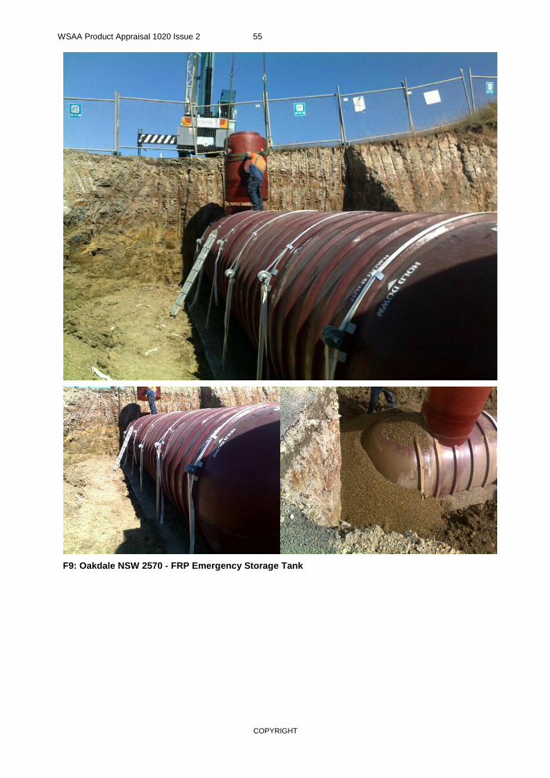
WSAA Product Appraisal 1020 Issue 2 55
COPYRIGHT
F9: Oakdale NSW 2570 - FRP Emergency Storage Tank

WSAA Product Appraisal 1020 Issue 2 56
COPYRIGHT
APPENDIX G – WARRANTY FOR MULLALY FRP PUMP STATION
NOTE: This warranty is only for the pump stations and does not cover the emergency storage tanks. The Emergency storage tanks warranty is on a project specific basis.

WSAA Product Appraisal 1020 Issue 2 57
COPYRIGHT

WSAA Product Appraisal 1020 Issue 2 58
COPYRIGHT
APPENDIX H – COUNCIL & WATER AUTHORITIES PRODUCT AUTHORISATION CERTIFICATES
H1 - CITY WEST WATER PRODUCT AUTHORISATION CERTIFICATE
Product Authorisation Certificate issued by City West Water Melbourne for use of Mullaly FRP Packaged Pump Station for Alternative Water Supply (Storm water) and Sewerage is shown below.

WSAA Product Appraisal 1020 Issue 2 59
COPYRIGHT
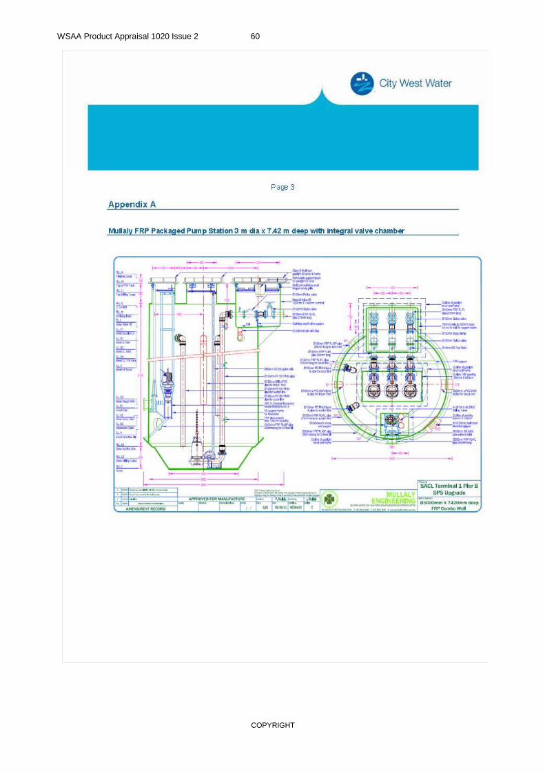
WSAA Product Appraisal 1020 Issue 2 60
COPYRIGHT

WSAA Product Appraisal 1020 Issue 2 61
COPYRIGHT
H2 - CAIRNS REGIONAL COUNCIL PRODUCT AAPROVAL CERTIFICATE
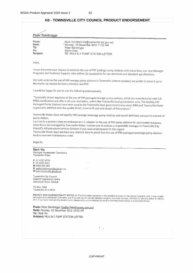
WSAA Product Appraisal 1020 Issue 2 62
COPYRIGHT
H3 - TOWNSVILLE CITY COUNCIL PRODUCT ENDORSEMENT

WSAA Product Appraisal 1020 Issue 2 63
COPYRIGHT
APPENDIX I - SUPPLIER CONTACTS
Supplier
Mullaly Engineering Pty Ltd
PO Box 266
Chester Hill NSW 2162
Tel. (02) 9644 9599
Fax. (02) 9644 5256
Contact person: Susan Owens
Email: [email protected]
Web: www.mullalyengineering.com.au
FRP tank manufacturer
Tank Solutions Pty Ltd
P O Box 623
Raymond Terrace NSW 2321
Tel. (02) 4964 8270
Fax. (02) 4964 8522
Contact person: Mike Palmer
Email: [email protected]
Web: www.tanksolutions.com.au
For QLD, FRP requirements
Professional Pump Services and Irrigation
in Townsville:
Contact: Peter Bainbridge
Phone: 07 4725 6860
Mobile: 0418 895 131
Address: 255 Dalrymple Service Road
Garbutt
E-Mail: [email protected]
Web: www.ppsnq.com.au
For VIC, , SA and WA - Mullaly Engineering
Pty Ltd
Contact: Robert Butterfield, Business
Development Manager Southern Region
Mobile: 0413 310 172
Phone: 03 9737 1970
Email: [email protected]

WSAA Product Appraisal 1020 Issue 2 64
COPYRIGHT
Melbourne Office
Suite 8.02 Level 8,
401 Docklands Drive Docklands VIC 3008
Phone: (03) 8605 7601 Fax: (03) 8605 7612 Sydney Office Level 11, 39 Martin Place Sydney NSW 2000
www.wsaa.asn.au