multiway switching controller design using fpgaicai.ektf.hu/icai2014/papers/icai.9.2014.2.57.pdf ·...
TRANSCRIPT

Multiway switching controller design usingFPGA∗
Szabolcs Szilágyi
Faculty of Informatics, University of Debrecen, [email protected]
Abstract
Multiway switching has become nowadays quite frequently used in build-ing wiring. It can be defined as an interconnection of two or more electricalswitches in order to control an electrical load from more than one location.Although the electrical load is often a lamp, electrical outlets, fans, pumps,heaters or other appliances, it can also be controlled by multiway switching.However, in this paper we will deal only with lighting systems.
Special switches are required to implement the system (three-way andfour-way switches) that have additional contacts, and extra wires must berun between them. In this way the light can be controlled from differentspots, e.g. the top and bottom of stairs or the end of a long hallway.
Externally there is a resemblance between these switches and the standardsingle-pole ones. Extra connections make possible the control of a circuit frommultiple locations. By connecting one or more four-way switches in-line, withthree-way switches at either end, the light can be controlled from three ormore locations. Toggling any switch changes the state of the light from offto on, or from on to off.
We would like to introduce a solution in this paper, based on FPGA forthe mentioned system and using HDL. The aim is to attain a high level ofgeneralization by applying any (even quite large) number of switches andlights.
Keywords: multiway switching, FPGA, controller, HDL
1. Introduction
Multiway Switching is a switching system used in building wiring. It ensures thecontrol of one or more electrical loads using two or more switches activated fromdifferent locations. The loads can be light bulbs, pumps or ventilators [1]. In
∗The work was supported by the TÁMOP-4.2.2.C-11/1/KONV-2012-0001 project. The projecthas been supported by the European Union, co-financed by the European Social Fund.
Proceedings of the 9th International Conference on Applied InformaticsEger, Hungary, January 29–February 1, 2014. Vol. 2. pp. 57–63
doi: 10.14794/ICAI.9.2014.2.57
57

this paper we use the terminology of “light bulbs” for the load, but in the real lifedevelopment it may represent any kind of electrical load.
Let’s take two practical examples, where these control systems can be applied.First of all, consider buildings with multiple floors. Suppose that we live in a storeyhouse and arrive home late from work when it’s already dark. It is a standardrequirement today that we switch on the light at the ground floor, get upstairs andturn off the light, there is no need to walk down again to switch it off. We maythink of long corridors too: instead of having only one switch at the end of thecorridor it is more favorable to install a switch next to each door.
Now, let us see in detail, how these systems work. Consider the simplest exam-ple, when the system contains only two switches. (see Figure 1.)
Figure 1: Classical multiway switching with 2 switches
In this case we use two three-way switches which allow us to control the systemfrom two different locations. The number of light bulbs is arbitrary. The idea is toconnect them to the system in a parallel way. To understand the main principleof the system, we use the following notations: if the position of the switch is left,
58 Sz. Szilágyi

we use 0, if it is right, we use 1. By applying two switches, four cases can beencountered. To represent these cases, we used the reflected binary code, alsoknown as Gray code (see e.g. [2,3]). In two cases the light bulbs will be on andin the other two they will be off (see Table 1.). We can notice that a next state isalways the opposite of the previous one.
Case SW1 SW2 Light(a) 0 0 OFF(b) 0 1 ON(c) 1 1 OFF(d) 1 0 ON
Table 1: ON/OFF table for multiway switching with 2 switches
If we would like to enlarge the system with more switches we need four-wayor crossover switches. The rule is that these have to be connected between thethree-way switches as it can be seen on the Figure 2.
In this example we used three switches, but the same logic can be extended formultiple switches. We can state that a system with N switches must contain twothree-way switches and N-2 four-way switches. In the case of a system with threeswitches, eight different states are possible, where in four cases the light bulbs willbe on, and in the other cases, the light bulbs will be off (see Figure 2.). In thiscase, for the representation of the system states, the Gray code was used similarly,having the main properties that the Hamming distance between the current stateand the next system state is always one (see e.g. [2,3]). The following chart (Table2.) shows that in the case of three switches the next state is always the opposite ofthe previous one, and the light bulb will be on only if an odd number of switchesare on.
Case SW1 SW2 SW3 Light(a) 0 0 0 OFF(b) 0 0 1 ON(c) 0 1 1 OFF(d) 0 1 0 ON(e) 1 1 0 OFF(f) 1 1 1 ON(g) 1 0 1 OFF(h) 1 0 0 ON
Table 2: ON/OFF table for multiway switching with 3 switches
Multiway switching controller design using FPGA 59
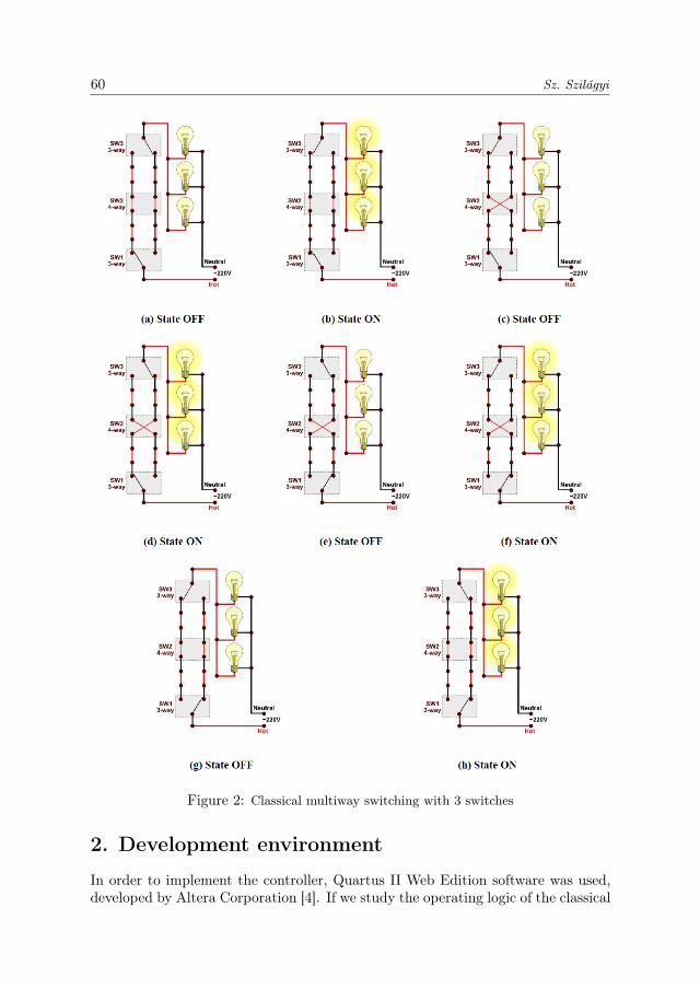
Figure 2: Classical multiway switching with 3 switches
2. Development environment
In order to implement the controller, Quartus II Web Edition software was used,developed by Altera Corporation [4]. If we study the operating logic of the classical
60 Sz. Szilágyi

multiway switching we get to the conclusion that it is enough to examine parityto control the multiway switching system. We should also take into considerationthat the HDL code written by us should be universal and portable. The controllerwas implemented using VHDL then Verilog language (see e.g. [5]-[7]). DesigningN number of inputs makes possible to control a multiway switching system withN switches. Although the controller has only one output, just like the classicalmultiway switching systems, unidentified number of loads, in this case bulbs canbe connected to it. Similar FPGA controllers have been designed by other peopletoo (see e.g. [8,9]). The pseudo-code of our design is as shown below:
Pseudo-code:
generic (N : integer := N);port (inputs : in std_logic_vector(N-1 downto 0);
output : out std_logic);PROCESS (inputs)
VARIABLE temp : std_logic;BEGIN temp := ’0’;
for I in 0 to N-1 looptemp := temp xor inputs(I);
end loop;output <= temp;
END PROCESS;
On Figure 3. we can see the implementation of a controller which is capableto direct a system with 3 switches and 3 bulbs. As we have already mentioned,the Quartus II software makes this possible. In this case the value of N is 3, andthis code determines the controller. (On Figure 3. it is marked with mws_3.) Weconnect 3 switches (SW2-SW0) to the input of the controller by the help of a bus.There are also 3 parallel red LEDs (LEDR0-LEDR2) bound to the output. Thenumber of bulbs (LEDs) is optional.
Figure 3: Controller design for a system with 3 switches usingQuartus II
The compilation of the project is followed by the simulation process with thehelp of the well-known Quartus II software [4]. We can see the results on Figure 4.
Multiway switching controller design using FPGA 61
It is evident that a certain output state is the opposite of the former one and theoutput will be active only if an odd number of inputs (switches) are on.
Figure 4: Simulation results for a system controller with 3 inputs
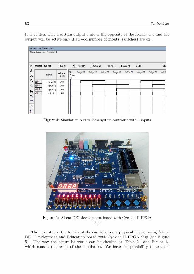
Figure 5: Altera DE1 development board with Cyclone II FPGAchip
The next step is the testing of the controller on a physical device, using AlteraDE1 Development and Education board with Cyclone II FPGA chip (see Figure5). The way the controller works can be checked on Table 2. and Figure 4.,which consist the result of the simulation. We have the possibility to test the
62 Sz. Szilágyi

FPGA controller for systems with different sizes because the card has 10 single poleswitches (SW0-SW9), 10 red LEDS (LEDR0-LEDR9) and 8 green LEDS (LEDG0-LEDG7) [10]. Satisfactory results can be obtained in each case.
3. Conclusions
We managed to design an FPGA based controller, which fulfills the multiwayswitching system requirements. The HDL code used for the implementation isuniversal and portable. Our solution eliminates the use of four-way and three-wayswitches [11], which are more expensive: our system uses N pieces of two-way Sin-gle Pole, Single Throw (SPST) switches. Another advantage of the using FPGAcontrollers is that the system is controlled by low pressure current circuit. Thecontroller presented by us is used most efficiently at new buildings.
References
[1] “Multiway switching.” Wikipedia: The Free Encyclopedia, Wikimedia Foundation,Inc., 10 Apr. 2014. http://en.wikipedia.org/wiki/Multiway_switching.
[2] DORAN, R. V., The Gray Code, Journal of Universal Computer Science, Vol. 13,No. 11 (2007), 1573–1597.
[3] DEWAR, M., STEVENS, B., Ordering Block Designs – Gray Codes, Universal Cyclesand Configuration Orderings, Springer Science+Business Media, ISBN 978-1-4614-4325-4 (2012).
[4] ALTERA official homepage, www.altera.com, downloaded on 15 Apr. 2014.
[5] HASKELL, R. E., HANNA, D. M., Digital Design using Digilent FPGA Boards –VHDL/ Active-HDL Edition, 2nd Edition, LBE Books, LLC, ISBN 978-0-9801337-8-3 (2012).
[6] BROWN, S., VRANESIC, Z., Fundamentals of Digital Logic with VHDL Design,3rd Edition, McGraw-Hill, ISBN 978-0-07-352953-0 (2009).
[7] HASKELL, R. E., HANNA, D. M., Introduction to Digital Design using DigilentFPGA Boards – Block Diagram/ Verilog Examples, LBE Books, LLC, ISBN 978-0-9801337-6-9 (2009).
[8] DILIP, B., ALEKHYA, Y., BHARATHI, P. D., FPGA Implementation of an Ad-vanced Traffic Light Controller using Verilog HDL, International Journal of AdvancedResearch in Computer Engineering & Technology, Vol. 1, Issue 7 (2012), 1–6.
[9] NATH, S., PAL, C., SAU, S., MUKHERJEE, S., ROY, A., GUCHHAIT, A., KAN-DAR, D., Design of an FPGA Based Intelligence Traffic Light Controller with VHDL,2012 International Conference on Radar, Communication and Computing, India(2012), 92–97.
[10] TERASIC official homepage, www.terasic.com, downloaded on 20 Apr. 2014.
[11] LITCHFIELD, M., McALISTER, M., Wiring Complete – Expert Advice from Startto Finish, Revised Edition, Taunton Press, Inc., (2008).
Multiway switching controller design using FPGA 63