muto comfort dormotion xl 150/80 l 80products.dorma.com/content/download/40696/448642/936015...
TRANSCRIPT
Installation instructions -
Ceiling mount with DORMOTION (Glass door)
with sidelites
MUTO COMFORT DORMOTION
XL 150/80
L 80
—
DORMA USA, Inc. Dorma Drive, Drawer AC Toll-Free: 800-523-8483 E-mail: dormaarchitectural@dorma. com
936015 04/17 Reamstown, PA 17567 Fax: 800-274-9724 Subject to change without notice
TABLE OF CONTENTS—
Overview
Intended use
Ceiling requirements and fi ttings
Requirements for glass panel
Safety instructions
Symbols used - safety/ installation
Maintenance, care, repair
Disposal 3
Specifi cations
Technical data 3
Tempered laminate glass and adhesive specifi cations 4
Overall view 5
Single sidelite mount
Multiple sidelite mount 6
INSTALLATION INSTRUCTIONS
Securing gasket to track 7
SIDELITE:
Securing track and sidelite section profi le to mounting surface
Installing u-channel for sidelite 8
Installing sidelite glass
Installing sidelite glass fi ller panel 9
Installing sidelite glass gasket 10
Installing the roller carriers: on monolithic glass ONLY 11
Installing the roller carriers: on tempered laminate glass ONLY 12
ANTI-JUMP:
Disengaging the anti-jump 10
Engaging the anti-jump 15
DORMOTION Unit:
Installing DORMOTION 13
Installing DORMOTION start/stops 17
END STOPS:
Installing end stops 7
Adjustment end stop location: LEADING end stop
Adjustment end stop location: TRAILING end stop 16
FLOOR GUIDE:
Installing fl oor guide 14-15
Installing glass/rollers on track 14
Installing cover clips
Installing brush profi le 18
Install view protection clips 19
Installing cover and view protection profi le
Installing end caps (optional) 20
ADJUSTMENTS:
Adjustment door height 15
Adjustment end stop location: LEADING end stop
Adjustment end stop location: TRAILING end stop 16
DORMA USA, Inc. Dorma Drive, Drawer AC Toll-Free: 800-523-8483 Website: www.dorma.com
936015 04/17 Reamstown, PA 17567 Fax: 800-274-9724 Subject to change without notice
MUTO COMFORT DM XL150/80 / L80 - SIDELITE MOUNT—
3
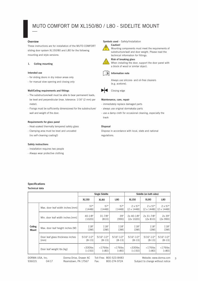
Symbols used – Safety/Installation
Caution! Mounting components must meet the requirements of
substructure/wall and door weight. Please read the
technical information for fittings.
Risk of breaking glass When installing the door, support the door panel with
a block of wood or similar object.
Information note
Always use silicone- and oil-free cleaners
(e.g. acetone).
Closing edge
Maintenance, care, repair
- immediately replace damaged parts
- always use original dormakaba parts
- use a damp cloth for occasional cleaning, especially the
track
Disposal
Dispose in accordance with local, state and national
regulations.
OverviewThese instructions are for installation of the MUTO COMFORT
sliding door system XL150/80 and L80 for the following
mounting and style versions:
1. Ceiling mounting
Intended use
- for sliding doors in dry indoor areas only
- for manual slow opening and closing only
Wall/Ceiling requirements and fittings
- The substructure/wall must be able to bear permanent loads,
be level and perpendicular (max. tolerance: 1/16" (2 mm) per
meter).
- Fixings must be sufficiently dimensioned for the substructure/
wall and weight of the door.
Requirements for glass panel
- Heat-soaked thermally tempered safety glass
- Clamping area must be level and uncoated
(no self-cleaning coating!)
Safety instructions
- Installation requires two people
- Always wear protective clothing
Single Sidelite Sidelite (on both sides)
XL150 XL80 L80 XL150 XL80 L80
CeilingMount
Max. door leaf width inches [mm]57"
[1448]
57"
[1448]
57"
[1448]
2 x 57"
[2 x 1448]
2 x 57"
[2 x 1448]
2 x 57"
[2 x 1448]
Min. door leaf width inches [mm]40-1/8"
[1020]
31-7/8"
[810]
39"
[990]
2x 40-1/8"
[2x 10²⁰]
2x 31-7/8"
[2x 810]
2x 39"
[2x 990]
Max. door leaf height inches [M]118"
[3M]
118"
[3M]
118"
[3M]
118"
[3M]
118"
[3M]
118"
[3M]
Door leaf glass thickness inches
[mm]
5/16"-1/2"
[8-13]
5/16"-1/2"
[8-13]
5/16"-1/2"
[8-13]
5/16"-1/2"
[8-13]
5/16"-1/2"
[8-13]
5/16"-1/2"
{8-13]
Door leaf weight lbs [kg]<330lbs
[<150]
<176lbs
[<80]
<176lbs
[<80]
<330lbs
[<150]
<176lbs
[<80]
<176lbs
[<80]
Technical data
Specifications
DORMA USA, Inc. Dorma Drive, Drawer AC Toll-Free: 800-523-8483 Website: www.dorma.com
936015 04/17 Reamstown, PA 17567 Fax: 800-274-9724 Subject to change without notice
MUTO COMFORT DM XL150/80 / L80 - SIDELITE MOUNT—
4
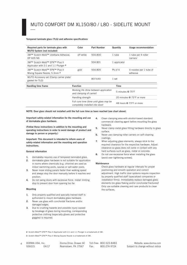
Required parts for laminate glass with MUTO System (not included)
Color Part Number Quantity Usage recommendation
3M™ Scotch-Weld™ Urethane Adhesive,
DP 605 NS
off white 934.800 1 tube 1 tube per 4 roller
carriers
3M™ Scotch-Weld™ EPX™ Plus II
Applicator with 2:1 and 1:1 Plunger 2
934.801 1 applicator
3M™ Scotch-Weld™ EPX™ Plus II
Mixing Square Nozzle, 5.3mm 3gold 934.805 Pk of 4 4 nozzles per 1 tube of
adhesive
MUTO Accessory set (Clamp carrier plate/
gasket for TLG)807.640 1 set
Handling time frame Function Time
Working life (time between application and clamping of carrier)
5 minutes @ 75°F
Handling strength 20 minutes @ 73°F or more
Full cure time (time until glass may be completely installed into door)
48 hours @ 73°F or more
NOTE: Door glass should not installed until the full cure time as been reached (see chart above).
2 Scotch-Weld™ EPX™ Plus II Applicator with 2:1 and 1:1 Plunger is a trademark of 3M.
3 Scotch-Weld™ EPX™ Plus II Mixing Square Nozzle is a trademark of 3M.
Important safety-related information for the mounting and use of dormakaba glass hardware.
(Follow these instructions in addition to the mounting and operating instructions in order to avoid damage of product and damage to person or property.)
Important: This document is intended to inform users of safety-related information and the mounting and operation instructions.
General information
1. dormakaba requires use of tempered laminated glass.
2. dormakaba glass hardware is not suitable for application
in rooms where chemicals (e.g. chlorine) are used as
indoor swimming pools, saunas or salt-water pools.
3. Never move sliding panels faster than walking speed
and always stop the door manually before it reaches end
position.
4. Do not swing doors with excessive force. Install limiting
stop to prevent door from opening too far.
Mounting
1. Only properly qualified and specially trained staff is
authorized to mount dormakaba glass hardware.
2. Never use glass with conchoidal fractures and/or
damaged edges.
3. Due to crushing hazards and possible injury caused
by breakage of glass during mounting, corresponding
protective clothing (especially gloves and protective
goggles) is required.
4. Clean clamping area with alcohol-based standard
commercial cleaning agent before mounting the glass
hardware.
5. Never clamp metal glass fitting hardware directly to glass
surface.
6. Never use clamping roller carriers on self-cleaning
coatings.
7. When adjusting glass elements, always stick to the
required clearance for the respective hardware. Adjust
clearance so glass does not come in contact with any
hard surfaces such as glass, metal or concrete.
8. Do not use excessive force when installing the glass
(avoid over tightening screws).
Maintenance Check glass hardware at regular intervals for proper
positioning and smooth operation and correct
adjustment. High traffic door systems require inspection
by properly qualified staff (specialized companies or
installation firms). Immediately replace damaged glass
elements (no glass flaking and/or conchoidal fractures)!
Only use suitable cleaning and care products to clean
the surfaces.
Tempered laminate glass (TLG) and adhesive specifications
DORMA USA, Inc. Dorma Drive, Drawer AC Toll-Free: 800-523-8483 Website: www.dorma.com
936015 04/17 Reamstown, PA 17567 Fax: 800-274-9724 Subject to change without notice
MUTO COMFORT DM XL150/80 / L80 - SIDELITE MOUNT—
5
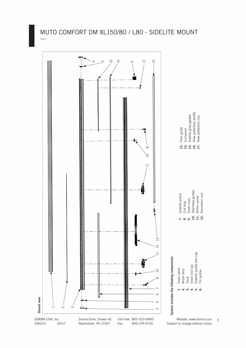
Syst
em in
clud
es t
he f
ollo
win
g co
mpo
nent
s:
1.
Cove
r panel
2.
Bru
sh s
trip
3.
Tra
ck
4.
Cove
r end c
ap
5.
Sid
elite
pro
fi le
end c
ap
6.
Fill pro
fi le
7.
Sid
elite
pro
fi le
8.
End s
top
9.
Cove
r clips
10
. S
tart
/sto
p g
uid
es
11
. R
oller
carr
ier
12
. D
orm
oti
on u
nit
Ove
rall
view
1
87
64
32
10
511
12
13
11
14
10
8
91554
13
. Flo
or
guid
e
14
. U
-channel
15
. S
idelite
gla
ss g
ask
et
16
. Vie
w p
rote
cti
on p
rofi le
17
. Vie
w p
rote
cti
on c
lip
17
16
DORMA USA, Inc. Dorma Drive, Drawer AC Toll-Free: 800-523-8483 Website: www.dorma.com
936015 04/17 Reamstown, PA 17567 Fax: 800-274-9724 Subject to change without notice
MUTO COMFORT DM XL150/80 / L80 - SIDELITE MOUNT—
6
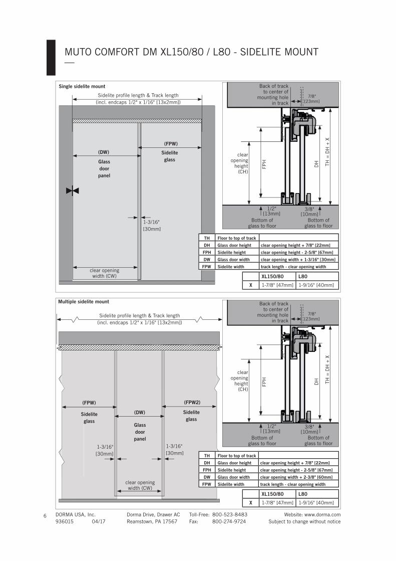
XL150/80 L80
X 1-7/8" [47mm] 1-9/16" [40mm]
Single sidelite mount
Sidelite profile length & Track length
(incl. endcaps 1/2" x 1/16" [13x2mm])
Multiple sidelite mount
1-3/16"
[30mm]
Sidelite glass
clear opening
width (CW)
Glass door panel
TH Floor to top of track
DH Glass door height clear opening height + 7/8" [22mm]
FPH Sidelite height clear opening height - 2-5/8" [67mm]
DW Glass door width clear opening width + 1-3/16" [30mm]
FPW Sidelite width track length - clear opening width
1-3/16"
[30mm]
1-3/16"
[30mm]
clear opening
width (CW)
Sidelite glass
Glass door panel
Sidelite glass
Sidelite profile length & Track length
(incl. endcaps 1/2" x 1/16" [13x2mm])
(DW)
(FPW)
DH
3/8"[10mm]
Bottom of
glass to floor
Back of track
to center of
mounting hole
in track
7/8"
[23mm]
clear
opening
height
(CH)
Bottom of
glass to floor
1/2"[13mm]
TH
= D
H +
X
FPH
(DW)
(FPW) (FPW2)
XL150/80 L80
X 1-7/8" [47mm] 1-9/16" [40mm]
TH Floor to top of track
DH Glass door height clear opening height + 7/8" [22mm]
FPH Sidelite height clear opening height - 2-5/8" [67mm]
DW Glass door width clear opening width + 2-3/8" [60mm]
FPW Sidelite width track length - clear opening width
DH
3/8"[10mm]
Bottom of
glass to floor
Back of track
to center of
mounting hole
in track
7/8"
[23mm]
clear
opening
height
(CH)
Bottom of
glass to floor
1/2"[13mm]
TH
= D
H +
X
FPH
DORMA USA, Inc. Dorma Drive, Drawer AC Toll-Free: 800-523-8483 Website: www.dorma.com
936015 04/17 Reamstown, PA 17567 Fax: 800-274-9724 Subject to change without notice
MUTO COMFORT DM XL150/80 / L80 - SIDELITE MOUNT—
7
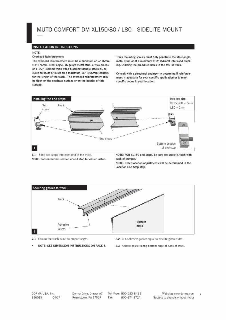
INSTALLATION INSTRUCTIONS
NOTE: Overhead Reinforcement:The overhead reinforcement must be a minimum of ¼” (6mm) x 3” (76mm) steel angle, 16 gauge metal stud, or two pieces of 1 1/2” (38mm) thick wood blocking (double stacked), se-cured to studs or joists on a maximum 16” (406mm) centers for the length of the track. The overhead reinforcement may be flush on the overhead surface or on the interior of this surface.
Track mounting screws must fully penetrate the steel angle, metal stud, or at a minimum of 2” (51mm) into wood block-ing, utilizing the predrilled holes in the MUTO track.
Consult with a structural engineer to determine if reinforce-ment is adequate for your specific application or to meet specific codes in your location.
1.1 Slide end stops into each end of the track.
NOTE: Loosen bottom section of end stop for easier install.NOTE: FOR XL150 end stops, be sure set screw is flush with back of bumper.NOTE: Exact location/adjustments will be determined in the Location End Stop step.
1
Track
End stops
Set
screw
Bottom section
of end stop
Installing the end stops Hex key size:
XL150/80 = 3mm
L80 = 2mm
2.1 Ensure the track is cut to proper length.
NOTE: SEE DIMENSION INSTRUCTIONS ON PAGE 6.
2.2 Cut adhesive gasket equal to sidelite glass width.
2.3 Adhere gasket along bottom edge of back of track.
2
Securing gasket to track
Adhesive
gasket
Sidelite glass
Track
DORMA USA, Inc. Dorma Drive, Drawer AC Toll-Free: 800-523-8483 Website: www.dorma.com
936015 04/17 Reamstown, PA 17567 Fax: 800-274-9724 Subject to change without notice
MUTO COMFORT DM XL150/80 / L80 - SIDELITE MOUNT—
8
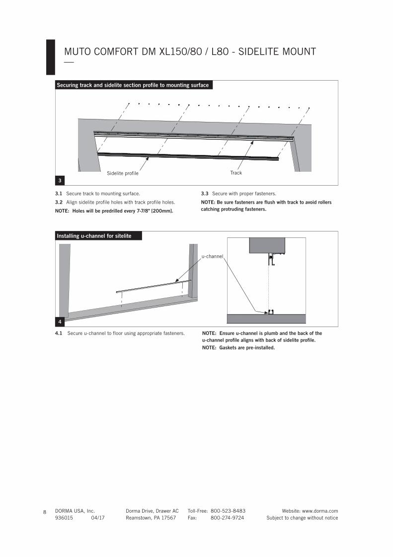
4.1 Secure u-channel to floor using appropriate fasteners. NOTE: Ensure u-channel is plumb and the back of the u-channel profile aligns with back of sidelite profile.NOTE: Gaskets are pre-installed.
Installing u-channel for sitelite
4
u-channel
3.1 Secure track to mounting surface.
3.2 Align sidelite profile holes with track profile holes.
NOTE: Holes will be predrilled every 7-7/8" [200mm].
3.3 Secure with proper fasteners.
NOTE: Be sure fasteners are flush with track to avoid rollers catching protruding fasteners.
3Sidelite profile Track
Securing track and sidelite section profile to mounting surface
DORMA USA, Inc. Dorma Drive, Drawer AC Toll-Free: 800-523-8483 Website: www.dorma.com
936015 04/17 Reamstown, PA 17567 Fax: 800-274-9724 Subject to change without notice
MUTO COMFORT DM XL150/80 / L80 - SIDELITE MOUNT—
9
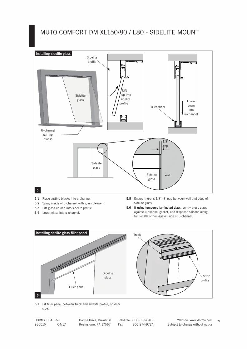
5.1 Place setting blocks into u-channel.
5.2 Spray inside of u-channel with glass cleaner.
5.3 Lift glass up and into sidelite profile.
5.4 Lower glass into u-channel.
5.5 Ensure there is 1/8" [3] gap between wall and edge of
sidelite glass.
5.6 If using tempered laminated glass, gently press glass
against u-channel gasket, and dispense silicone along
full length of non-gasket side of u-channel.
5
Installing sidelite glass
U-channel
setting
blocks
Sidelite
profile
Sidelite
glass
U-channel
Lift
up into
sidelite
profileLower
down
into
u-channel
Sidelite
glass
1/8"
gap
Sidelite
glass
Wall
6.1 Fit filler panel between track and sidelite profile, on door
side.
6
Installing sitelite glass filler panel
Filler panel
Sidelite
glass
Track
Sidelite
profile
DORMA USA, Inc. Dorma Drive, Drawer AC Toll-Free: 800-523-8483 Website: www.dorma.com
936015 04/17 Reamstown, PA 17567 Fax: 800-274-9724 Subject to change without notice
MUTO COMFORT DM XL150/80 / L80 - SIDELITE MOUNT—
10
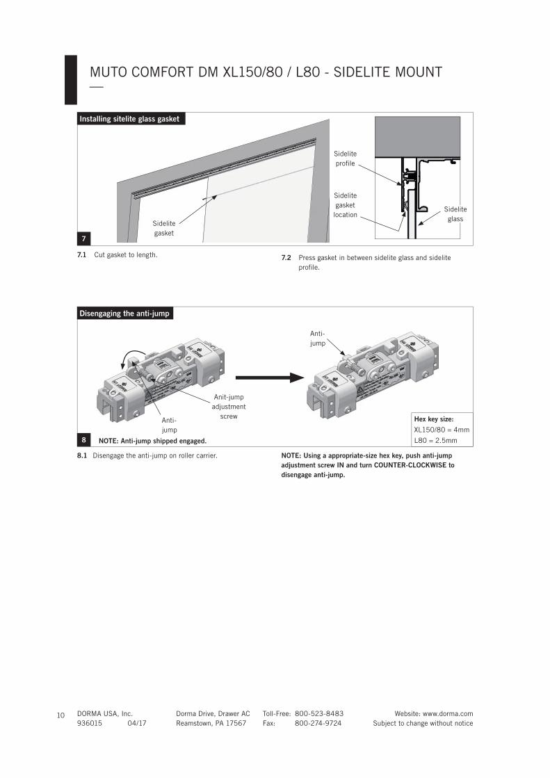
8.1 Disengage the anti-jump on roller carrier. NOTE: Using a appropriate-size hex key, push anti-jump adjustment screw IN and turn COUNTER-CLOCKWISE to disengage anti-jump.
8
Anit-jump
adjustment
screwAnti-
jump
Anti-
jump
Disengaging the anti-jump
Hex key size:
XL150/80 = 4mm
L80 = 2.5mmNOTE: Anti-jump shipped engaged.
7.1 Cut gasket to length.
7
7.2 Press gasket in between sidelite glass and sidelite
profile.
Installing sitelite glass gasket
Sidelite
gasket
Sidelite
gasket
location
Sidelite
profile
Sidelite
glass

DORMA USA, Inc. Dorma Drive, Drawer AC Toll-Free: 800-523-8483 Website: www.dorma.com
936015 04/17 Reamstown, PA 17567 Fax: 800-274-9724 Subject to change without notice
MUTO COMFORT DM XL150/80 / L80 - SIDELITE MOUNT—
11
Installing the roller carriers: on monolithic glass ONLY
NOTE: FULLY CLEAN SURFACE OF GLASS WITH AN ALCOHOL-BASED MILD GLASS AND SURFACE CLEANER. ENSURE NO DEBRIS IS ON THE GASKET.
9A.1 Slide roller carriers onto glass.
9A.2 Slide glass gasket and metal shim between glass and
roller carrier.
NOTE: Orient gasket with rubber side facing the glass.9A.3 Secure roller carriers to glass using appropriate-size hex
key at 10 ft lbs (14 Nm).
Hex key size:
XL150/80 = 4mm
L80 = 2.5mm
Glass
gasket (Front of) Glass9A
Roller location on glass with DORMOTION unit
XL150/80 L80
Single door X 3-1/8" [80] 3-1/8" [80]
Double door X 1-9/16" [40] 1-9/16" [40]
Single door Z 1-9/16" [40] 1-9/16" [40]
Double door Z 2-3/8" [60] 2-3/8" [60]
Z
X
DETERMINE THE LEADING (X) VERSUS TRAILING (Z) EDGE OF THE GLASS. "LEADING IS SIDE CLOSEST TO LATCH (CLOSED)."
Secure Roller
carrier
Legend: leading edge
of glass
Torque value:
10ft lbs (14Nm)
(Front of) Glass
DORMA USA, Inc. Dorma Drive, Drawer AC Toll-Free: 800-523-8483 Website: www.dorma.com
936015 04/17 Reamstown, PA 17567 Fax: 800-274-9724 Subject to change without notice
MUTO COMFORT DM XL150/80 / L80 - SIDELITE MOUNT—
12
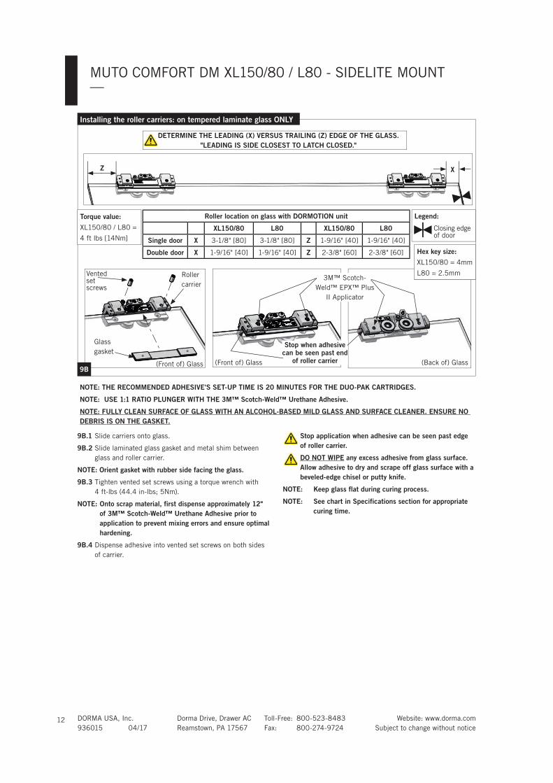
NOTE: THE RECOMMENDED ADHESIVE'S SET-UP TIME IS 20 MINUTES FOR THE DUO-PAK CARTRIDGES.
NOTE: USE 1:1 RATIO PLUNGER WITH THE 3M™ Scotch-Weld™ Urethane Adhesive.
NOTE: FULLY CLEAN SURFACE OF GLASS WITH AN ALCOHOL-BASED MILD GLASS AND SURFACE CLEANER. ENSURE NO DEBRIS IS ON THE GASKET.
9B.1 Slide carriers onto glass.
9B.2 Slide laminated glass gasket and metal shim between
glass and roller carrier.
NOTE: Orient gasket with rubber side facing the glass.
9B.3 Tighten vented set screws using a torque wrench with
4 ft-lbs (44.4 in-lbs; 5Nm).
NOTE: Onto scrap material, first dispense approximately 12" of 3M™ Scotch-Weld™ Urethane Adhesive prior to application to prevent mixing errors and ensure optimal hardening.
9B.4 Dispense adhesive into vented set screws on both sides
of carrier.
Stop application when adhesive can be seen past edge of roller carrier.
DO NOT WIPE any excess adhesive from glass surface. Allow adhesive to dry and scrape off glass surface with a beveled-edge chisel or putty knife.
NOTE: Keep glass flat during curing process.
NOTE: See chart in Specifications section for appropriate curing time.
Installing the roller carriers: on tempered laminate glass ONLY
(Front of) Glass
Roller
carrier
Glass
gasket
Ventedset screws
3M™ Scotch-
Weld™ EPX™ Plus
II Applicator
Stop when adhesive can be seen past end
of roller carrier9B
Z X
Roller location on glass with DORMOTION unit
XL150/80 L80 XL150/80 L80
Single door X 3-1/8" [80] 3-1/8" [80] Z 1-9/16" [40] 1-9/16" [40]
Double door X 1-9/16" [40] 1-9/16" [40] Z 2-3/8" [60] 2-3/8" [60]
DETERMINE THE LEADING (X) VERSUS TRAILING (Z) EDGE OF THE GLASS. "LEADING IS SIDE CLOSEST TO LATCH CLOSED."
Hex key size:
XL150/80 = 4mm
L80 = 2.5mm
Torque value:
XL150/80 / L80 =
4 ft lbs [14Nm]
Legend:
Closing edge of door
(Front of) Glass (Back of) Glass
DORMA USA, Inc. Dorma Drive, Drawer AC Toll-Free: 800-523-8483 Website: www.dorma.com
936015 04/17 Reamstown, PA 17567 Fax: 800-274-9724 Subject to change without notice
MUTO COMFORT DM XL150/80 / L80 - SIDELITE MOUNT—
13
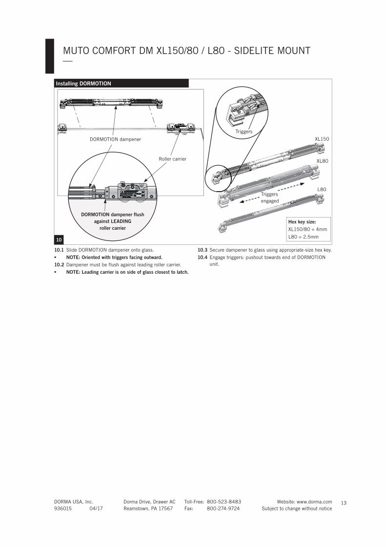
10.1 Slide DORMOTION dampener onto glass.
NOTE: Oriented with triggers facing outward.10.2 Dampener must be flush against leading roller carrier.
NOTE: Leading carrier is on side of glass closest to latch.
10.3 Secure dampener to glass using appropriate-size hex key.
10.4 Engage triggers: pushout towards end of DORMOTION
unit.
10
Installing DORMOTION
XL80
XL150DORMOTION dampener
L80
X
L8L8
Triggers
Roller carrier
DORMOTION dampener flush against LEADING
roller carrierHex key size:
XL150/80 = 4mm
L80 = 2.5mm
Triggers
engaged
DORMA USA, Inc. Dorma Drive, Drawer AC Toll-Free: 800-523-8483 Website: www.dorma.com
936015 04/17 Reamstown, PA 17567 Fax: 800-274-9724 Subject to change without notice
MUTO COMFORT DM XL150/80 / L80 - SIDELITE MOUNT—
14
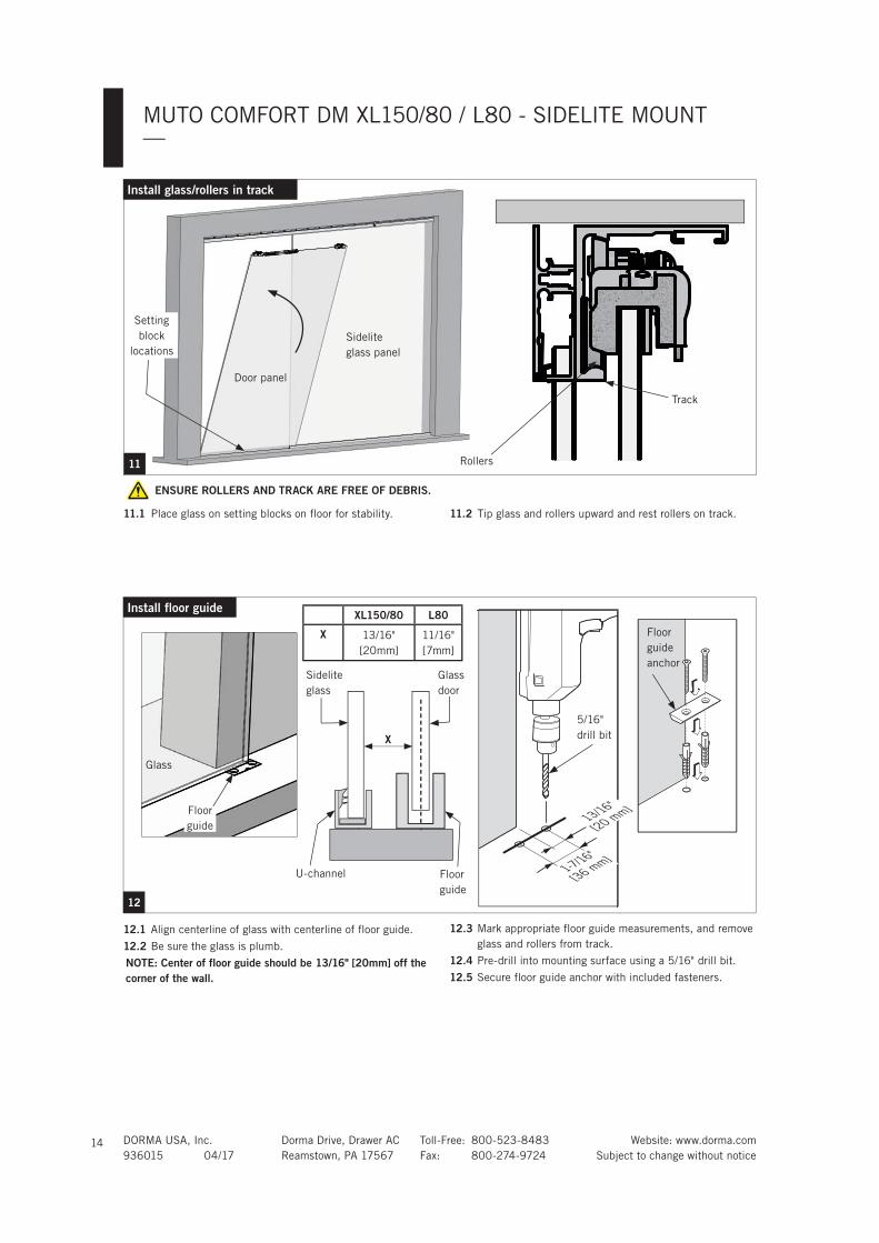
ENSURE ROLLERS AND TRACK ARE FREE OF DEBRIS.
11.1 Place glass on setting blocks on floor for stability. 11.2 Tip glass and rollers upward and rest rollers on track.
11
Setting
block
locations
Door panel
Sidelite
glass panel
Install glass/rollers in track
Rollers
Track
12
Glass
Install floor guide
12.1 Align centerline of glass with centerline of floor guide.
12.2 Be sure the glass is plumb.
NOTE: Center of floor guide should be 13/16" [20mm] off the corner of the wall.
12.3 Mark appropriate floor guide measurements, and remove
glass and rollers from track.
12.4 Pre-drill into mounting surface using a 5/16" drill bit.
12.5 Secure floor guide anchor with included fasteners.
Floor
guide
anchor
1-7/16"
[36 mm]
13/16"
[20 mm]
5/16"
drill bit
Glass
door
X
Floor
guide
Sidelite
glass
U-channel
Floor
guide
XL150/80 L80
X 13/16"
[20mm]
11/16"
[7mm]
DORMA USA, Inc. Dorma Drive, Drawer AC Toll-Free: 800-523-8483 Website: www.dorma.com
936015 04/17 Reamstown, PA 17567 Fax: 800-274-9724 Subject to change without notice
MUTO COMFORT DM XL150/80 / L80 - SIDELITE MOUNT—
15
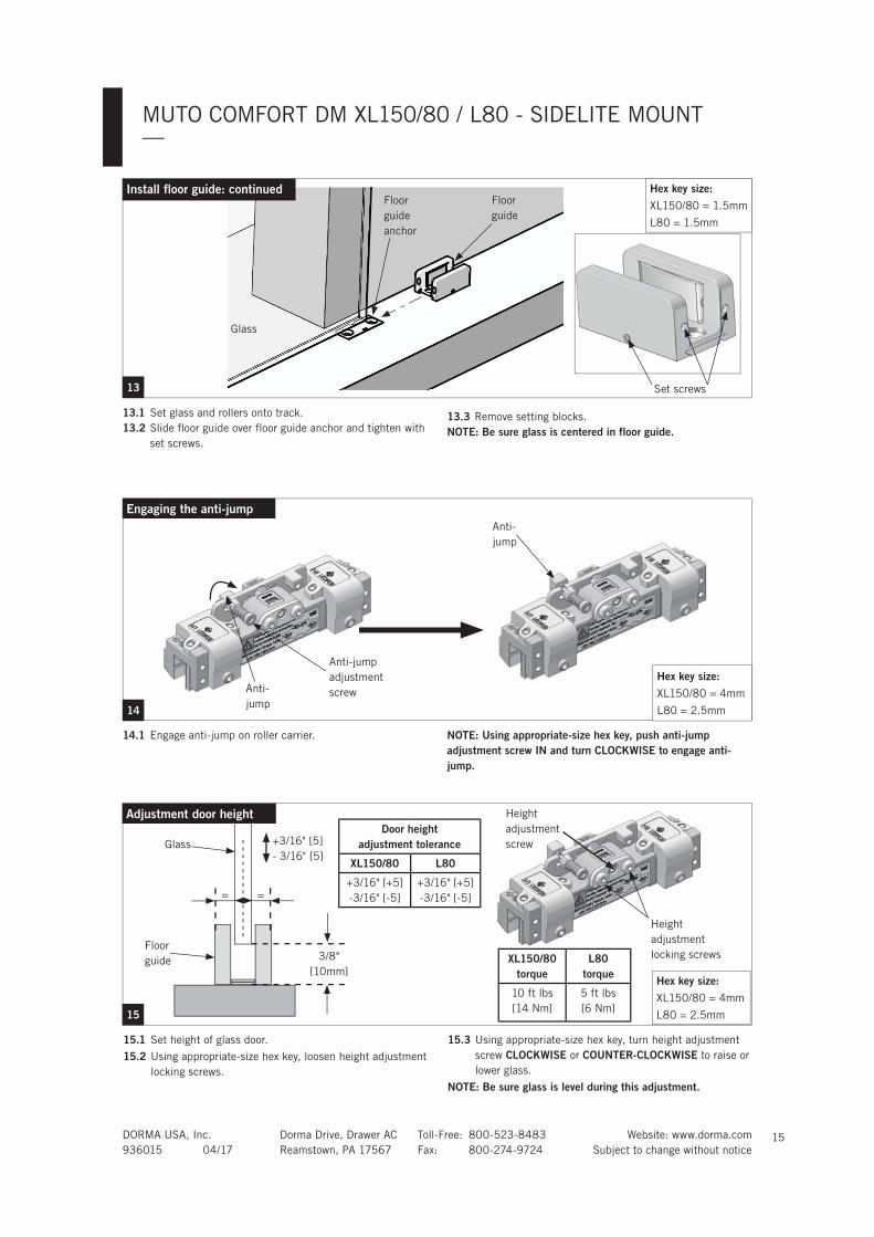
15.1 Set height of glass door.
15.2 Using appropriate-size hex key, loosen height adjustment
locking screws.
15.3 Using appropriate-size hex key, turn height adjustment
screw CLOCKWISE or COUNTER-CLOCKWISE to raise or
lower glass.
NOTE: Be sure glass is level during this adjustment.
15
Height
adjustment
locking screwsXL150/80torque
L80torque
10 ft lbs
[14 Nm]
5 ft lbs
[6 Nm]
Height
adjustment
screw
Hex key size:
XL150/80 = 4mm
L80 = 2.5mm
Door height adjustment tolerance
XL150/80 L80
+3/16" [+5]
-3/16" [-5]
+3/16" [+5]
-3/16" [-5]
14.1 Engage anti-jump on roller carrier. NOTE: Using appropriate-size hex key, push anti-jump adjustment screw IN and turn CLOCKWISE to engage anti-jump.
14
Anti-
jump
Anti-jump
adjustment
screw
Anti-
jump
Engaging the anti-jump
Hex key size:
XL150/80 = 4mm
L80 = 2.5mm
Glass
Floor
guide 3/8"
[10mm]
13.1 Set glass and rollers onto track.
13.2 Slide floor guide over floor guide anchor and tighten with
set screws.
13.3 Remove setting blocks.
NOTE: Be sure glass is centered in floor guide.
13
Floor
guide
Floor
guide
anchor
Glass
Install floor guide: continued
Set screws
Adjustment door height
= =
Hex key size:
XL150/80 = 1.5mm
L80 = 1.5mm
+3/16" [5]
- 3/16" [5]

DORMA USA, Inc. Dorma Drive, Drawer AC Toll-Free: 800-523-8483 Website: www.dorma.com
936015 04/17 Reamstown, PA 17567 Fax: 800-274-9724 Subject to change without notice
MUTO COMFORT DM XL150/80 / L80 - SIDELITE MOUNT—
16
16
Adjustment end stop location: LEADING end stop
0mm
Door opened
0mm
Hex key size:
XL150/80 = 3mm
L80 = 2mm
Handle to frame edge distance.*Verify with local jurisdiction.*
LOCATION OF GLASS DOOR
TO FRAME EDGE.
Glass
Handle
Frame
edge
Glass
edge
max. 1-3/16"
[30mm]
Glass overlap of door frame
END STOP LOCATION:LEADING EDGE
Handle
Glass
Frame
edgeGlass
edge
Bumper
Secure
XL150/80torque
L80torque
3 ft lbs
[4 Nm]
2.2 ft lbs
[3 Nm]min. 1"
[25mm]
min. 1"
[25mm]16
BumperEdge of roller
carrier
End
stop Door closed
NOTE: Pair of doors:Be sure there is a 1/4" [6mm] gap between the two doors.
Set end stop locations:16.1 Slide end stop to
desired location
on track. Bumper
should touch edge
of roller carrier.
Bumper
Secure
XL150/80torque
L80torque
3 ft lbs
[4 Nm]
2.2 ft lbs
[3 Nm]
Set end stop locations:16.1 Slide end stop to
desired location
on track. Bumper
should touch edge
of roller carrier.
Hex key size:
XL150/80 = 3mm
L80 = 2mm
NOTE: Pair of doors:Be sure there is a 1/4" [6mm] gap between the two doors.
END STOP LOCATION:TRAILING EDGE
BumperEdge of roller
carrier
End
stop
Handle to frame edge distance.*Verify with local jurisdiction.*
Adjustment end stop location: TRAILING end stop
LOCATION OF GLASS DOOR
TO FRAME EDGE.
DORMA USA, Inc. Dorma Drive, Drawer AC Toll-Free: 800-523-8483 Website: www.dorma.com
936015 04/17 Reamstown, PA 17567 Fax: 800-274-9724 Subject to change without notice
MUTO COMFORT DM XL150/80 / L80 - SIDELITE MOUNT—
17
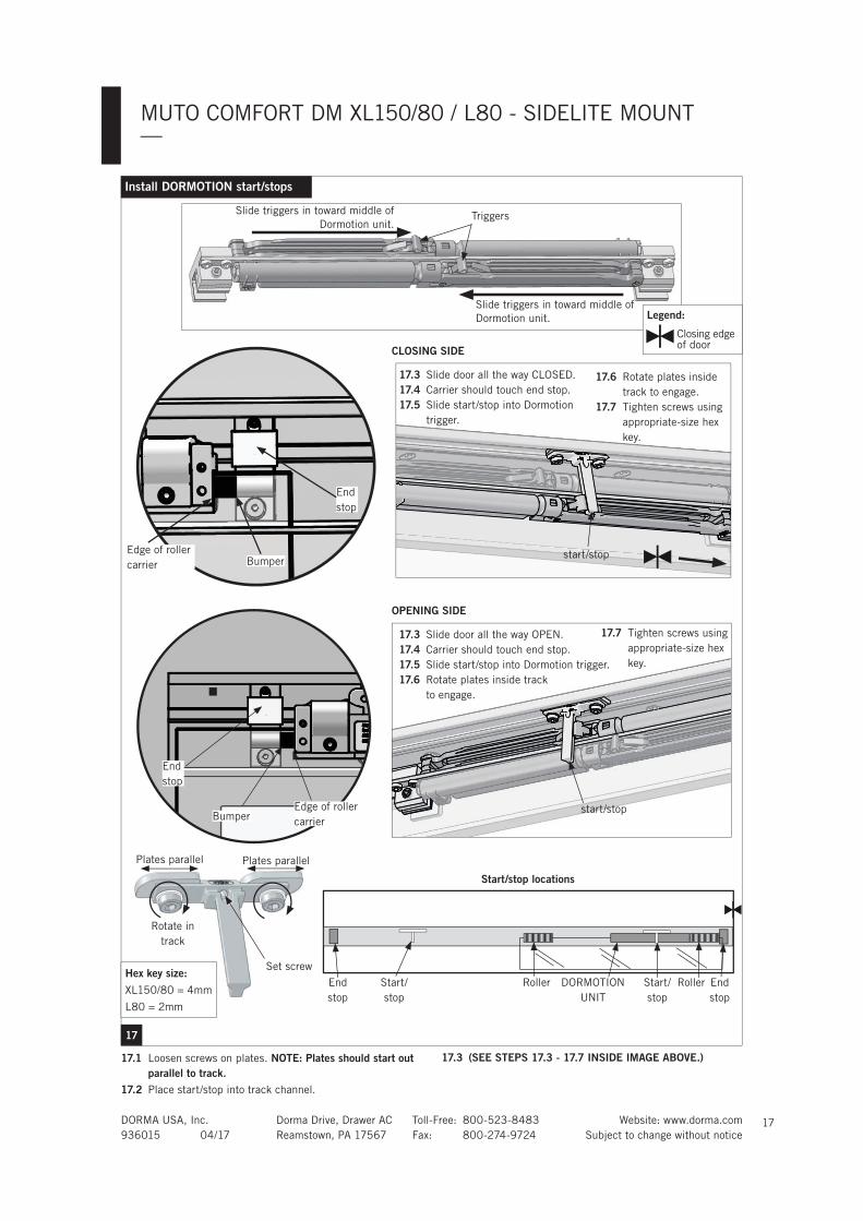
17.1 Loosen screws on plates. NOTE: Plates should start out parallel to track.
17.2 Place start/stop into track channel.
17.3 (SEE STEPS 17.3 - 17.7 INSIDE IMAGE ABOVE.)
17
Install DORMOTION start/stops
Triggers
Plates parallel Plates parallel
Rotate in
track
Set screw
Start/stop locations
End
stop
End
stop
Start/
stop
Start/
stop
Roller DORMOTION
UNIT
Roller
BumperEdge of roller
carrier
End
stop
BumperEdge of roller
carrier
End
stop
Slide triggers in toward middle of
Dormotion unit.
17.3 Slide door all the way CLOSED.
17.4 Carrier should touch end stop.
17.5 Slide start/stop into Dormotion
trigger.
Legend:
Closing edge of door
Slide triggers in toward middle of
Dormotion unit.
17.6 Rotate plates inside
track to engage.
17.7 Tighten screws using
appropriate-size hex
key.
17.3 Slide door all the way OPEN.
17.4 Carrier should touch end stop.
17.5 Slide start/stop into Dormotion trigger.
17.6 Rotate plates inside track
to engage.
17.7 Tighten screws using
appropriate-size hex
key.
Hex key size:
XL150/80 = 4mm
L80 = 2mm
CLOSING SIDE
OPENING SIDE
start/stop
start/stop

DORMA USA, Inc. Dorma Drive, Drawer AC Toll-Free: 800-523-8483 Website: www.dorma.com
936015 04/17 Reamstown, PA 17567 Fax: 800-274-9724 Subject to change without notice
MUTO COMFORT DM XL150/80 / L80 - SIDELITE MOUNT—
18
18.1 Insert cover clips into track. (One clip per foot) 18.2 Insert perpendicular to track, and turn CLOCKWISE to
snap into place.
Install cover clips
19.1 Measure and cut brush to appropriate length.
19
Install brush profile
18
Cover
clip
19.2 Slide brush into cover.
Brush
Cover

DORMA USA, Inc. Dorma Drive, Drawer AC Toll-Free: 800-523-8483 Website: www.dorma.com
936015 04/17 Reamstown, PA 17567 Fax: 800-274-9724 Subject to change without notice
MUTO COMFORT DM XL150/80 / L80 - SIDELITE MOUNT—
19
20.1 Slide door open until it meets the end stop.
20.2 Measure and cut view protection profile to fit into empty
sliding portion of track - 3/16" [5].
Install view protection clips
Empty sliding portion of track
20.3 Tip profile up and snap down into track as shown.
20.4 Snap view protection clips onto inside of cover as shown.
• Use minimum 1 clip per foot of profile.
• Exception: If profile is minimum of 1 foot in length, use
2 clips.
View protection
profile
Door panel Sidelite glass
(Slide door panel)
View
protection clip
TO BE USED WITH ONE OR MULTIPLE SIDELITE APPLICATIONS.
Cover
View
protection
clips
20
DORMA USA, Inc. Dorma Drive, Drawer AC Toll-Free: 800-523-8483 Website: www.dorma.com
936015 04/17 Reamstown, PA 17567 Fax: 800-274-9724 Subject to change without notice
MUTO COMFORT DM XL150/80 / L80 - SIDELITE MOUNT—
20
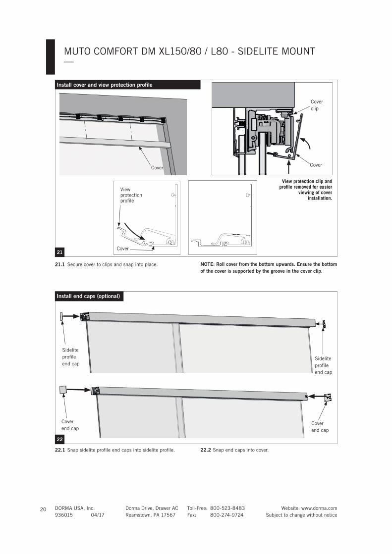
22.1 Snap sidelite profile end caps into sidelite profile.
Install end caps (optional)
Sidelite
profile
end cap
Cover
end capCover
end cap
22
22.2 Snap end caps into cover.
Sidelite
profile
end cap
21.1 Secure cover to clips and snap into place.
21
Cover
Install cover and view protection profile
NOTE: Roll cover from the bottom upwards. Ensure the bottom of the cover is supported by the groove in the cover clip.
Cover
Cover
clip
View
protection
profi le
View protection clip and profi le removed for easier
viewing of cover installation.
Cover

93
6015
04
/2017, S
ubje
ct
to c
hange w
ithout
notice
DORMA USA, INC.
DORMA DRIVE, DRAWER AC
REAMSTOWN, PA 17567
TOLL-FREE: 800-523-8483
FAX: 800-274-9724
E-MAIL: [email protected]
WWW.DORMA-USA.COM