n. asakura, k. shimizu, k. tobita japan atomic energy agency, naka us-japan workshop on fusion power...
TRANSCRIPT
N. Asakura, K. Shimizu, K. TobitaJapan Atomic Energy Agency, Naka
US-Japan Workshop on Fusion Power Plants and Related Advanced Technologies
UCSD, 23-24 Feb. 2010
Study of Power Exhaust in Edge and Divertor of the SlimCS Demo Reactor

CONTENTS
1. Introduction: power exhaust for DEMO divertor
2. Power handling in divertor (SOLDOR/NEUT2D) g eometry effect on detachment, Ar seeding
3. Development of Monte-Carlo simulation for Ar impurity seeding (SONIC)
4. Summary of power exhaust study for DEMO divertor
Pheat=600-700MW
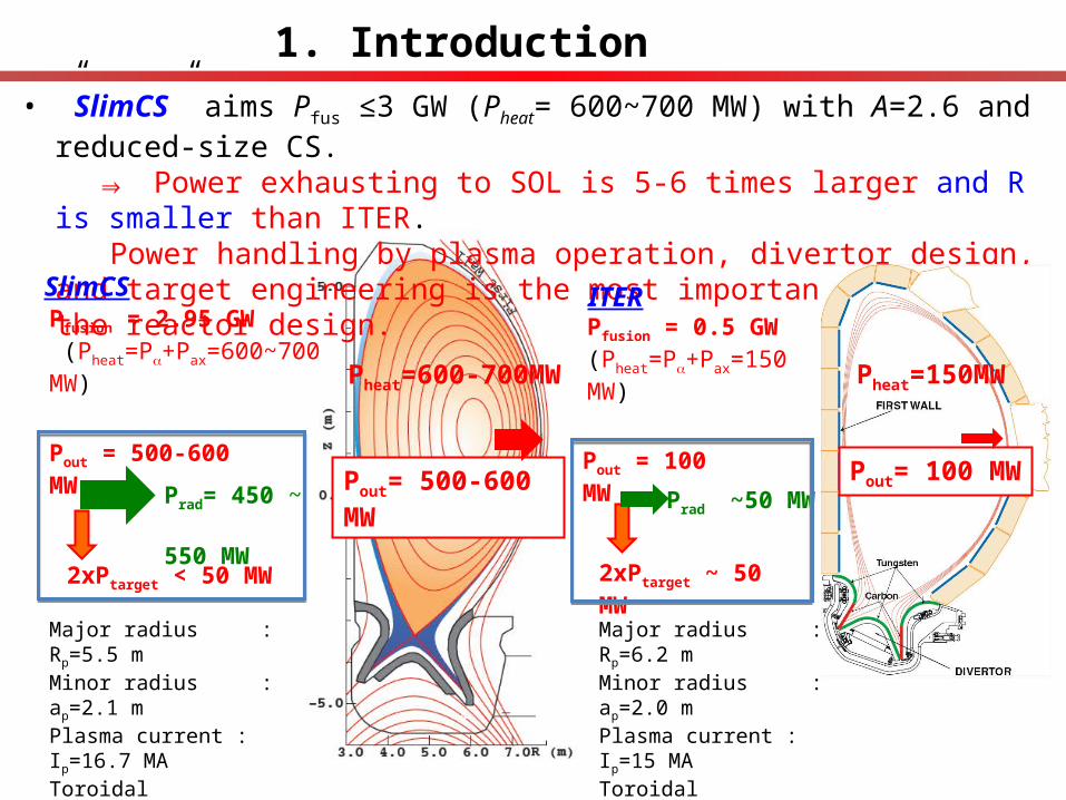
• ”SlimCS” aims Pfus ≤3 GW (Pheat= 600~700 MW) with A=2.6 and reduced-size CS. ⇒ Power exhausting to SOL is 5-6 times larger and R is smaller than ITER. Power handling by plasma operation, divertor design, and target engineering is the
most important issue for the reactor design.
1. Introduction
Major radius : Rp=6.2 m Minor radius : ap=2.0 mPlasma current : Ip=15 MAToroidal field : Bt=5.3 TPlasma volume : Vp=830 m3
Pout= 100 MW
Major radius : Rp=5.5 m Minor radius : ap=2.1 mPlasma current : Ip=16.7 MAToroidal field : Bt=6.0 TPlasma volume: Vp=941 m3
Pfusion = 2.95 GW (Pheat=P+Pax=600~700 MW)
SlimCSPfusion = 0.5 GW(Pheat=P+Pax=150 MW)
ITER
Prad= 450 ~ 550 MW
Pout = 500-600 MW
2xPtarget < 50 MW
Pout = 100 MW
2xPtarget ~ 50 MW
Prad ~50 MWPout= 500-600 MW
Pheat=150MW

Divertor pumping
impurity seeding
Long leg
Power handling in SlimCS divertor was studied using SOLDOR/NEUT2D code⇒SONIC Design concept for the ITER divertor is applied/extended to the DEMO divertor:“divertor detachment” (Te~ a few eV) is a key for the power handling
Divertor concept for ITER and DEMO reactors
Large inclination
V-shaped corner
(1) Divertor leg and inclination of the target are larger than ITER ⇒ increase radiation, CX & volume recombination at upstream, reducing qtarget. (2) V-shaped corner enhance recycling near the strike-point.⇒(3) impurity seeding such as Ar (Ne, N2, Kr, Xe) enhance edge & divertor radiation. ⇒

SONIC : self-consistent coupling with Ar impurity Monte Carlo has been developed for Ar seeding and transport SOLDOR/NEUT2D were used for DEMO divertor design, where Ar impurity radiation
with non-coronal model: Prad = L(Te,r) nzne, and constant nAr/ni was applied. [3]
SONIC
D neutral
D ion
[1,2] Ar impurity transportIonization processes: ionization charge exchange surface/volume recombinationIon transport processes: thermal force – friction force Ar0 atom dynamics
[1] K. Shimizu, et al., J. Nucl. Mater. 313-316 (2003) 1277 [3] H. Kawashima, et al. Nucl. Fusion 49 (2009) 065007[2] H. Kawashima, et al. J. Plasma Fusion Res. 1 (2006) 31

MC approach has advantages to impurity modelling
• Tracking impurity neutrals and ions
⇒ CX-loss, n-collision, recycling etc. Radiation & Recombination at
multi-charge states• Kinetic effect ⇒ Thermal force• Gyro-motion ⇒ Erosion (for PWI)
Most impurity transport processes are incorporated in original formula:
For self-consistent coupling of MC code, problems (long calculation time and MC noise) have been solved.
Kinetic thermal force (FTi) decreases with impurity ion speed (VI) approaching to ion thermal velocity (vth-i).
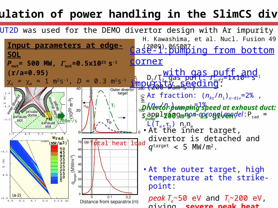
2. Simulation of power handling in the SlimCS divertor
Input parameters at edge-SOLPout= 500 MW, Γout=0.5x10²³ s-1 (r/a=0.95)i = e = 1 m2s-1, D = 0.3 m2s-1
• At the inner target, divertor is detached and qtarget 5 MW/m2.
• At the outer target, high temperature at the strike-point:
peak Te~50 eV and Ti~200 eV, giving severe peak heat load ~70 MW/m2 !
D2/T2 gas puff:Γpuff=1x10²³ s-1 (200 Pam3s-1) Ar fraction: (nAr/ni)o-div=2% , (nAr/ni)edge-SOL=1%applying non-coronal model:Prad = L(Te,r) nzne
Divertor pumping speed at exhaust duct:Spump= 200 m3s-1 is given.
200m3/s
SOLDOR/NEUT2D was used for the DEMO divertor design with Ar impurity radiation.H. Kawashima, et al. Nucl. Fusion 49 (2009) 065007
Case-1:pumping from bottom corner with gas puff and impurity seeding:
Total heat load

Case-2: Concept for the ITER divertor, “V-shaped corner”, is investigated
2.1 Power handling in divertor: divertor geometry
• Radiation loss at the outer divertor is increased at upstream of the strike point from 85 to 142 MW:
Total Prad(edge+div.) = 390 MW (Prad
edge~130MW, Praddiv~260MW)
•Peak Te~20 eV ,Ti~90 eV are smaller by the factor of 1/21/2.5.
Peak heat load is reduced from 70 MW/m2 to 27 MW/m2.
Conduction/convection heat load is reduced in the low Te divertor:
•Divertor recycling is increased from 3.7x1024 to 4.2x1024 s-1.
Total heat load

• Evaluation of major heat load on the target
qtarget = γ·nd·Csd·Td + nd·Csd·Eion + f(Prad) + f(1/2mv02n0v0)
Transport component(incl. electron&ion-
conduction/convection)
Surface-recombination loss radiation
power loadneutral
power load
Recombination and radiation power loads become important in high recycling divertor, while Conduction/Convection heat load is reduced
Case-1:pumping from bottom corner Case-2: “V-shaped divertor”

2.2 Power handling in divertor: increasing Ar seeding
•Large heat load extends in a wide divertor area, when Pradtot/Pout increased to ~92%:
Peak heat load in the detached divertor, qpeak 9 MWm-2, is attributed to Radiation/Neutral flux and their distributions in the divertor. Modelling (understanding) of impurity transport in the edge and divertor is crucial
for improvement of the heat handling scenario with single/multi-impurity seeding.
Case-3: increasing Ar ion in the outer divertor (nAr/ni)odiv=5% is investigated.
Case-2: nAr/ni=2% Case-3:nAr/ni=5%
Intense radiation area (and plasma detachment) extending to wide and upstream in the divertor
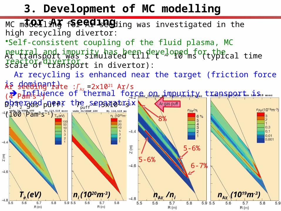
3. Development of MC modelling for Ar seeding
Ar transport was simulated till t ~ 10 ms (typical time scale of transport in divertor): Ar recycling is enhanced near the target (friction force is dominant) Influence of thermal force on impurity transport is observed near the separatrix
MC modelling for Ar seeding was investigated in the high recycling divertor: Self-consistent coupling of the fluid plasma, MC neutral and impurity has been developed for the reactor divertor.
nAr (1019m-3)
Ar seeding rate :ΓAr =2x10²¹ Ar/s (4 Pam3s-1)D2/T2 gas puff: Γpuff = 5x10²² s-1 (100 Pam3s-1)
8%
5-6%
6-7%5-6%
nAr /niTe (eV) ni (1020m-3)
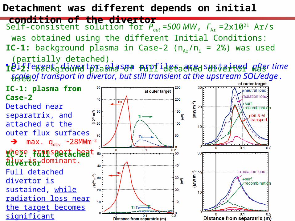
Detachment was different depends on initial condition of the divertor
Different divertor plasma profiles are sustained after time scale of transport in divertor, but still transient at the upstream SOL/edge.
IC-1: plasma from Case-2Detached near separatrix, and attached at the outer flux surfaces max. qdiv ~28MWm-2 where transport heat flux is dominant.
IC-2: full detached divertorFull detached divertor is sustained, while radiation loss near the target becomes significant max. qdiv ~18MWm-2
where radiation heat flux is dominant.
Self-consistent solution for Pout =500 MW, ΓAr =2x10²¹ Ar/s was obtained using the different Initial Conditions:
IC-1: background plasma in Case-2 (nAr/ni = 2%) was used (partially detached).IC-2: background plasma of full detached divertor was used.

Radiation power load from MC modelling (div. transport time scale) is dominant more than Non-coronal model and Constant nAr/ni Region with large radiation loss (>50 MWm-3) is localized just above the target, while the full detachment is sustained in divertor transport time scale (IC-2 case).
3
3.2
2.2
nAr (1019m-3) Radiation power (MWm-3)
IC-2: full detached divertor caseRadiation power and its heat load contribution
Ar transport to the upstream SOL/edge is not long enough: radiation at SOL/edge, Prad
edge ~ 20MW, is smaller than Pradedge~130MW (nAr/ni ~1%)
Investigation of Ar transport and radiation power at SOL/edge is necessary to determine appropriate or combination of the radiators.
4. Summary of power exhaust study for the DEMO divertor
• Huge power handling (Pout =500MW) for SlimCS (Pfusion≤3GW) was investigated
Intense Ar concentration (nAr/ni~5%) in the long-leg and V-shaped divertor produced the detached divertor (Prad
tot/Pout ~ 92% : PradSOL/edge/Pout ~26% and Prad
div/Pout ~66% )
⇒ Peak heat load qtarget~9MW/m2 , which was attributed mostly to radiation and neutral flux are dominant, compared to transport (conv. and cond.) heat flux.
SONIC with impurity MC has been developed for the Ar impurity seeding.
Self-consistent coupling of the fluid plasma, MC neutral and impurity has been developed for the reactor divertor:
Ar transport was simulated untill t ~ 10 ms (time scale of impurity transport in divertor), but still transient at the upstream SOL/edge.
⇒ Region with large radiation loss (>50 MWm-3) is localized just above the target, while the full detachment is sustained in divertor transport time scale.
Radiation profile in steady-state and penetration to SOL/ edge/ core plasma will be calculated to determine an appropriate radiator or the combination.
The previous work by SOLDOR&NEUT2D(non-coronal model & constant nAr/ni) showed
Distribution of the radiation region over a wide area (edge and divertor) will be required in order to avoid local overheating of Plasma Facing Components.
Issues for the DEMO divertor design
• Design for particle control should be improved to satisfy DEMO divertor functions: He exhaust requires the large divertor pumping Formation of the detached divertor requires high neutral pressure and radiation. Development of SONIC with multi-species (Ar and He) MDs started from 2009.
Restrictions of the power handling (nimp/ni and PradSOL/edge ) such as due to influence of
the divertor and degradation of core plasma performance is investigated.
• Large power handling at the main SOL and Edge is required for the DEMO plasma:
Future issues in power handling scenario:
Understanding of physics process and Improve of modelling under the ITER/DEMO-level high recycling divertor are required, such as
atomic/molecule/impurity processes (n-n/i-n collision, photon absorption, MAR) ,
thermal stability of the divertor plasma with seeding and metallic (high-Z) impurities.
⇒ Development/ improvement of plasma operation, divertor design, and target engineering are required for consistent heat handling scenario.
Desirable heat load of tentative target design (W, RAFMS, water-cooling) is 5-7MWm-2.

Issues for the DEMO divertor (in addition)
Future issues in power handling scenario for engineering and PSI:For the divertor target of W (PFC) & RAFM (sturacture material) & water cooling, allowable heat flux is tentatively expected to 5-7 MW/m2.Design of materials, their specific joining and heat sink will be improved to increase qmax and their enginnering reliability.
Plasma Facing Component issues for W-PWI are pointed out in order to extrapolate from ITER to DEMO: Dependence/threshold of He irradiation effects, Neutron irradiation effects (defect, blistering by ions, increasing DBTT&T-retention) on temperature, fluence and energy under ITER-level conditions.
Target design/arrange of mono-block armors and melt-layer dynamics.
On the other hand, fluences of D/T/He ions and neutrons in the DEMO reactors-level are far beyond existing database.

Estimation of computer time for steady-state distribution( t~1s)
JAEA parallel computer: effective speed20GFlopsIFARC parallel computer: effective speed 100TFlops 100TFlops/20GFlops = 5000 times faster
SONIC calculation: 3ms ~ 9 hours 1s/0.003s = 333 times more required
Then, SONIC calculation in steady-state (1s) will need 9 hrs x 333/5000 = 0.6 hr

• Gas puff (Γpuff) is increased to 2x10²³ s-1
2.2 Gas puff and Impurity (Ar) seeding in V-shaped divertor
• Pumping rate pump is increased from 2% to 3-4% by increase the neutral density.
Additional gas puff/ Ar seeding will enhance divertor radiation for qtarget ~ 9 MWm-2
Ar fraction is increased to (nAr/ni)odp =5%Fix Γpuff=1x10²³ s-1
Case-2
allowable power handling level
Fix (nAr/ni)odp=2%Case-2
allowable power handling level

19
Impurity and neutral treatment
• Ar fraction (nAr/ni) is given.
• Radiation loss power is evaluated by Wr=-nenzLz(Te).
• Loss rate Lz(Te) is used on neres=1x10¹⁶ s/m3.
• Assumed W wall, which reflection coefficients of particle and energy are almost twice larger than that for carbon.
Impurity radiation: non-coronal model
Neutral reflection: W target model

Understanding of Kinetic Thermal Force
The definition of kinetic thermal force : the momentum change by Coulomb collisionis integrated over ion distribution distorted due to ion temperature gradient.
divertor
T1 T2
T1 < T0 < T2T
0
T
0
mfp
f1f0
F1+
F0-
F0+
F2-
F1+ > F0
-
Fnet > 0
V0 ~ 0
f2
f0
F2- < F0
+
Fnet > 0
composite force
V0 ~ vthi
F1+ < F0
-
Fnet < 0
F2- > F0
+
Fnet < 0
FTi(
r V 0 ) º òd
r ¢ v dfi(
r ¢ v )mI {Dv // }i
F0+ + F0
- = Fv f

Impurity MC was calculated in the background plasma/neutral distributions in the previous (nAr/ni)odiv =2% case Ar ions was traced up to t = 3.8 ms (transient phase)
• Conversion of Carbon MC calculation was determined by impurities with higher charged-state.

Radiation profile (MC result) was localized above the target
Radiation profile (MC result) was rather localized above the target, compared to the non-coronal model with (nAr/ni)odiv = const.
Radiation loss in the outer divertor was increasing during the MC calculation: Prad
o-div = 126 MW at t = 10 ms was smaller than 140 MW for Case-2.
Calculation to the conversion (near steady-state) will show larger radiation power from higher charge-state Ar ions at the upstream of the target.
Radiation power

4. Issue for impurity: dilution & He exhaust Ar seeding (nAr/ne=0.22 0.44%) ⇒ reduces Power to SOL (Pto-SOL
= 600 ⇒ 480MW), with expense of lowering Fusion power: PFusion
= 3.0 ⇒ 2.7GW (-10%). He concentration (nHe/ne=5 ⇒10%) largely reduces PFusion
=3.0 ⇒ 2.2GW (-27%) He exhaust is another important issue. • Particle control, i.e. geometry and pumping speed, impurity seeding, should be
determined to optimize the “divertor performance”, He exhaust requires divertor pumping
Large pumping flux
high neutral pressure
Divertor detachment is formed under high neutral pressure and radiation loss.

6. Issue for Plasma Facing Component (W-PWI) Tungsten is foreseen as PFCs (divertor and first wall) in DEMO reactor. PSI properties have been investigated for application of the ITER divertor. Following W-PWI issues/database should be focused under the high fluence:(1) “bubbles”, “holes”, “nano-structure” formation by He ion irradiation at Tw >700°C(2) Neutron irradiation effects : defect, blistering, increasing DBTT and T-retention.(3) Target design/arrange of mono-block armors and melt-layer dynamics.
ITER (1 shot) DEMO (continuous)
Tw at SS (°C) water-cool ~1000 [base 100-200] <1200 [base 290]
Te near strike-point (eV) 1-30 1-20
Fuel ion fluence (m-2) 5x1025 - 5x1026 (400s) 1030-1031 (~year)
He ion fluence (m-2) 1024 - 1025 (400s) 1029-1030 (~year)
Neutron fluence (dpa) ~0.5 (~5 year) 20-100 (~year)
Their dependence/threshold on temperature and fluence and energy are investigated in recent experiments under the ITER-level condition. On the other hand, fluences of D/T/He ions and neutrons in DEMO reactors are far beyond existing database.

5. Issue for heat load handling: target heat sink
Divertor ITER DEMO
Cooling tube Cu-alloy (CuCrZr) RAFM
Armor CFC/W W
Coolant water 100 , 4MPa℃ water 200 , 10MPa℃
Heat load ≤ 20 MW/m2 ≤ 10 MW/m2
Thermal conductivity1/10 of Cu
1/2 of ITER Handle power of x6
RAFM substrate
RAFM cooling tube
NiCuMn blazing
Ultimate design w/o margins!
Tungsten is foreseen as candidate for the high temperature PFC in DEMO reactor: low sputtering yield & high energy threshold and low T-retention.
W mono-block armor
Heat removal is expected to ½ of ITER divertor since lower thermal conductivity of RAFM (F82H: 1/10 of Cu) and higher temperature water (200 °C at the inlet).
(1) Higher base temperature Tbase~ 290°C (10MPa, 10 m/s) is required:• Irradiation embitterment at low temperature (<300°C) may occur (few database). • Tbase > 240°C to avoid corrosion by radiation-produced hydrogen peroxide (H2O2)• Sub-critical & Super-critical water (>20MPa) leads to enhance corrosion of RAFM.
Issue for heat load handling: target heat sink
Requirement
W T ≤ 1,200ºC
RAFM 290ºC ≤ T ≤ 550ºC
Recrystalization
Stress-creep
qmax
Possible to increase the thickness to ~2mm if allowed to use F82H above 550ºC
(2-1) allowable heat flux determined by thermal stress at F82H cooling pipe:
qmax ~ 5 MW/m2
Primary (pressure) +Secondary (thermal) Stress < 3Sm ( t 1mm F82H )
(2) Allowable heat flux is reduced to 5-7 MW/m2
(2-1) allowable heat flux determined by thermal analysis:
qmax ~ 7 MW/m2 (Tcoolant = 290ºC)
K. Tobita, et al. Nucl. Fusion 49 (2009) 075029