n t g a d c a mech 4240 c r s 2011 j 8, 2011 d b a …dbeale/mech4240-50/reports/neptune...
TRANSCRIPT

1
NEPTUNE TECHNOLOGY GROUP
AUTOMATED DATA COLLECTION FOR ANTENNAS
MECH 4240 CONCEPTS REVIEW
SUMMER 2011
JULY 8, 2011
DR. BEALE
AUBURN UNIVERSITY
MECHANICAL ENGINEERING
CORP 4 PROJECT GROUP
BENJAMIN BETHEL
GRAYSON DAWSON
CODY OWEN
KYLE PALMER
DANIEL PAULK
2
ABSTRACT:
The aim of this project is to design, test, and manufacture an automated moving carriage
that transports a receiver around a circular track. The motion of the carriage will meet or exceed
the requirements set forth by the sponsor, Neptune Technology. The carriage and track design
must be developed must be developed according to the systems engineering process outlined in
MECH-4240, Comprehensive Design 1. The purpose of this report is to detail and illustrate the
progress made towards the final design by showing the steps of a proper design analysis.
Important factors to be considered in this design include weight, cost, maintenance and
reliability, and a reduction of electromagnetic interference due to physical components. The
merits of each concept developed are discussed and evaluated against the overall design
requirements. The report covers four different working concepts, with the primary concept of a
battery-powered, motor controlled, gear driven system being recommended. Further design
plans for the battery powered design will be given at the conclusion of the concept review and
future plans for analysis and prototyping will be presented.

3
TABLE OF CONTENTS:
Abstract 2
List of Figures and Tables 4
Introduction 5
Mission Objective 6
Architectural Design Development 7
• Battery Powered/Wheel Driven Design 8
– Product Hierarchy 9
– First-Cut Bill of Materials 9
• Monorail Design 10
– Product Hierarchy 11
– First-Cut Bill of Materials 11
• Outlet Powered/Chain Driven Design 12
– Product Hierarchy 13
– First-Cut Bill of Materials 13
• Battery Powered/Chain Driven Design 14
– Product Hierarchy 15
– First-Cut Bill of Materials 15
Requirements 16
Concept of Operations 16
Validate and Verify 18
Mission Environment 19
Risk Management 19
Systems Design Engineering 20
Project Management 20
Conclusions 21
Appendix 22

4
LIST OF FIGURES:
Figure 1 – Typical Signal Strength Plot 6
Figure 2 – Corp_4 Functional Decomposition 7
Figure 3 – Battery Operated/Wheel Driven Platform 8
Figure 4 – Monorail Platform 10
Figure 5 – Outlet Powered/Chain Driven Platform 12
Figure 6 – Battery Powered/Chain Driven Platform 14
Figure 7 – Current Platform and Track 16
Figure 8 – Current Receiver Mount 17
Figure 9 – Conformal Coating 18
Figure 10 – Power, Torque, Velocity Curves 23
Figure 11 – Required motor speed vs. Required Motor Torque
for given Carriage velocities 24
Figure 12 – Motor Torque and Cart Velocity in English Units 25
LIST OF TABLES:
Table 1 – Bill of Materials: Battery Powered/Wheel Driven 9
Table 2 – Bill of Materials: Monorail 11
Table 3 – Bill of Materials: Outlet Powered/Chain Driven 13
Table 4 – Bill of Materials: Battery Powered/Chain Driven 15
Table 5 – Concept Comparison Chart 20
Table 6 – Design Schedule 22

5
INTRODUCTION:
The Neptune Technology Group has been a major producer of water meters since 1892
and since then, they have collected over 119 years of experience in better-quality service to the
water utility industry. Neptune Technology Group has been able to produce mobile data
collectors such as the MRX920 that has the ability to take 5,000 readings per hour along with
being wireless and weighing less than 5 pounds. Neptune Technology Group is a well
experienced and technologically advanced organization that will continue to be an aggressive
competitor in the water utility industry. The projects taken on by Neptune Technology Group,
such as automating the data collection process for antennas under test, go to show that they are
not slowing down anytime soon.
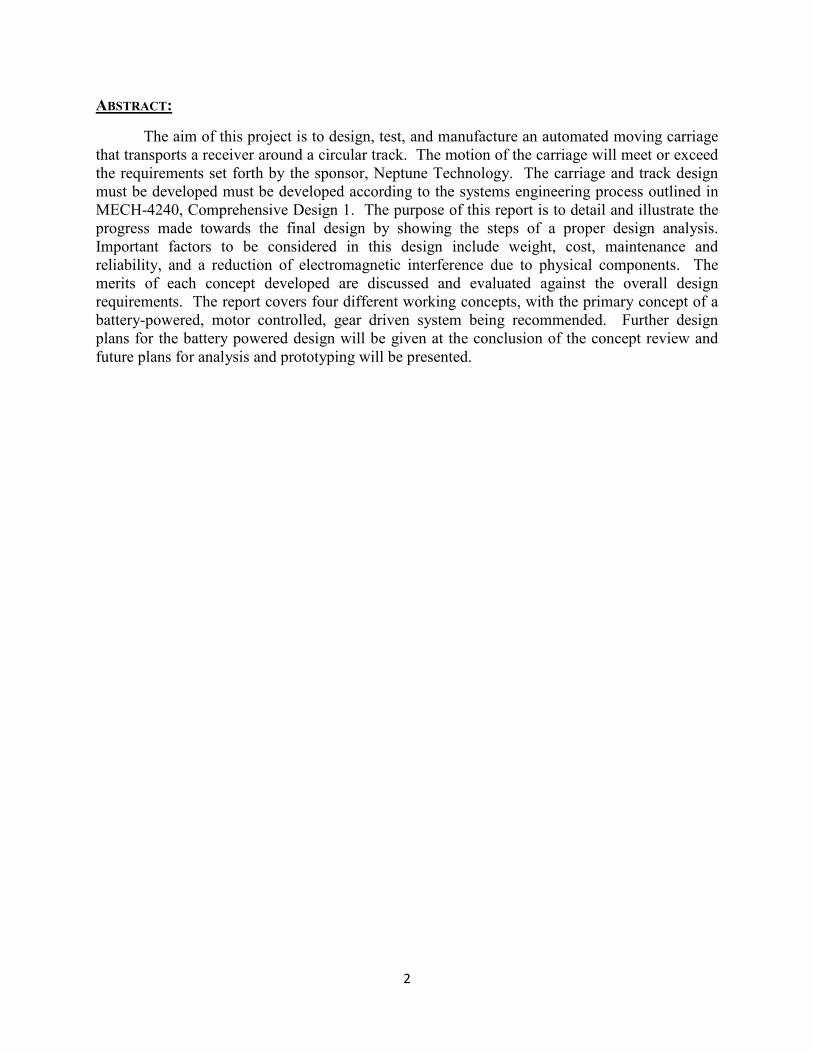
Neptune currently has an outdoor test setup comprised of a rolling carriage on a 50 ft.
diameter circular track. A test water meter is placed in the center of the track and emits a
wireless signal to a test antenna designed to measure the signal strength coming from the water
meter. An example of a typical signal strength measurement is shown in Figure 1. The test
antenna is mounted on the moving carriage and the carriage is moved to various locations around
the track by two technicians who manually collect data from the receiver. This set-up is time
consuming, uncomfortable, and inefficient.
The design task at hand is to create an automated receiver that will go along a track of 50
feet in diameter. There are currently no designs that will be sufficient at accomplishing this task,
so the goal behind the design will be to create and manufacture this automated receiver from
scratch. The design of the automated receiver and its components may be based off of a battery
powered roller coaster or a new design may be developed to accomplish the tasks described
above.
In this concepts review, a general overview of design ideas for the automated carriage is
presented. The purpose of this review is to convey the ideas of the designs considered for
production and to show which design best fulfills the mission objective stated below. A cost
analysis of each design will be shown as well as advantages and disadvantages of each design.
In conclusion of the review, the concept chosen for further design will be determined and future
plans for the chosen concept will be discussed.
6
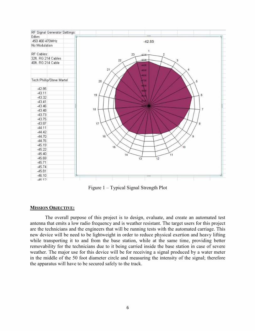
Figure 1 – Typical Signal Strength Plot
MISSION OBJECTIVE:
The overall purpose of this project is to design, evaluate, and create an automated test
antenna that emits a low radio frequency and is weather resistant. The target users for this project
are the technicians and the engineers that will be running tests with the automated carriage. This
new device will be need to be lightweight in order to reduce physical exertion and heavy lifting
while transporting it to and from the base station, while at the same time, providing better
removability for the technicians due to it being carried inside the base station in case of severe
weather. The major use for this device will be for receiving a signal produced by a water meter
in the middle of the 50 foot diameter circle and measuring the intensity of the signal; therefore
the apparatus will have to be secured safely to the track.

7
ARCHITECTURAL DESIGN DEVELOPMENT:
One of the first steps taken in the generation of concepts for this project was to create a
functional decomposition for the design. This tool enabled brainstorming ideas for the design on
a sub-function and a sub-sub function level, allowing the selection of a more feasible design.
Creating a functional decomposition is an important part of the Systems Engineering Process.
Corp_4’s functional decomposition is shown in the figure below (Figure 2).
Figure 2 – Corp_4 Functional Decomposition

8
CONCEPT 1: BATTERY POWERED, WHEEL DRIVEN
Advantages:
• Relatively inexpensive and lightweight design
• Steel carriage can be easily shaped, cut, bent, and welded
• Constant RF interference by motor that circles the track with the test antenna reducing
error in collected data
• Under heavy loads, material will bend before breaking
Disadvantages:
• Battery will have to be recharged/replaced frequently
• Possible slip between rollers and track
The battery powered/wheel driven design consists of a steel platform mounted on a set of
wheels in which the front axle is being driven by the battery powered DC motor. This design
will provide a constant radio frequency noise coming from the motor and will be accounted for
in the frequencies experienced from the receiver. The steel platform will be covered in a
material that will reduce corrosive effects since it will spend the majority of its time outside. The
electronics and the battery will be removable to reduce the risk of overheating the electronics.
The goal of the battery powered/wheel driven system is to reduce weight and maintenance while
having fewer moving parts. An image of the battery powered/wheel driven design is shown
below (Figure 1).
Figure 3 – Battery Operated/Wheel Driven Platform

9
PRODUCT HIERARCHY: Battery Powered/Wheel Driven Concept
• SUBSYSTEM 1: Power Motion
– DC Motor
– Battery
– Gear Driven Wheel
• SUBSYSTEM 2: Movement
– Forward/Reverse Motion
– Position
– Surface Contact
• SUBSYSTEM 3: Carriage Component
– Carry Electronics
– Environmental Protection
• SUBSYSTEM 4: Data Acquisition
– Display Data
– Collect Data
– Send/Receive Data
FIRST-CUT BILL OF MATERIALS: Battery Powered/Wheel Driven Platform
Table 1 – Bill of Materials: Battery Powered/Wheel Driven
Manufacturer Product Price Quantity Total
Weldasprocket (Tractor Supply Co.) Sprockets 37.99 1 37.99
Marathon Electric (Tractor Supply Co.) Electric Motor 109.99 1 109.99
MetalsDepot.com Stainless Steel 4'x4' 16 GA. Sheet 204 1 204
MetalsDepot.com Stainless Steel 1'x2' 0.25" Sheet 159 1 159
Northern SPAL 4" Miniseries fan 74.74 1 74.74
Tractor Supply Company Roller Chain, Size 40 16.99 16 271.84
Mapp Castor U-Groove Steel Wheels 81.66 4 326.64
MetalsDepot.com 2"x1"x16 GA. Rectangular Tubing 42 2 84
MetalsDepot.com 1.5" Round Cold Drawn Tubing 250 16 4000
Battery Source Battery 115 1 115
Total $5,383.20

10
CONCEPT 2: MONORAIL CONCEPT
Advantages:
• “Unlimited” access to power supply for motor
• Motor mounted on carriage to reduce RF error in readings taken
Disadvantages:
• Safety issues
• High cost
• Problematic maintenance, difficult to service due to limited market
• Overseas market
The monorail concept consists of a motor mounted on a carriage that drives a wheel via a
set of gears. The motor will receive power from the monorail that will be mounted to the
existing track and will also be able to reduce the RF interference. The platform will be fixed to 3
wheels with only one being driven by the motor. The wheels will fall in line with the angle iron
that will be bolted to the concrete pad keeping the carriage in its path. An image of the monorail
design is shown below (Figure 4).
Figure 4 - Monorail Platform (Tether cable not shown)

11
PRODUCT HIERARCHY: Monorail Concept
• SUBSYSTEM 1: Power Motion
– AC Motor
– Monorail
– Gear Driven Wheel
• SUBSYSTEM 2: Movement
– Forward/Reverse Motion
– Position
– Surface Contact
• SUBSYSTEM 3: Carriage Component
– Carry Electronics
– Environmental Protection
• SUBSYSTEM 4: Data Acquisition
– Display Data
– Collect Data
– Send/Receive Data
FIRST-CUT BILL OF MATERIALS: Monorail Platform
Table 2 – Bill of Materials: Monorail
Manufacturer Product Price Quantity Total
Northern Tool and Equipment 6 inch rubber wheel/tire 12.99 2 25.98
AngletonSalvage.com 2"x2" angle iron 32 16 512
Grizzly (Amazon) G8165 5" Heavy-Duty Fixed Caster 10.25 1 10.25
Weldasprocket (Tractor Supply Co.) Sprockets 37.99 4 151.96
Marathon Electric (Tractor Supply Co.) Electric Motor 109.99 1 109.99
MetalsDepot.com Stainless Steel 4'x4' 16 GA. Sheet 204 1 204
MetalsDepot.com Stainless Steel 1'x2' 0.25" Sheet 159 1 159
Northern SPAL 4" Miniseries fan 74.74 1 74.74
Concrete Pad 2000 1 2000
Gobrel Monorail 10000 1 10000
Total $13,247.92

12
CONCEPT 3: OUTLET POWERED, CHAIN DRIVEN DESIGN
Advantages:
• “Unlimited” access to power supply for motor (no recharges)
• Longer life for the electronics
Disadvantages:
• More moving parts, more friction than other concepts
• Chain stretching inevitable
• More costly compared to other designs
This design choice makes it much easier to reduce weight on the carriage itself since the
motor will be place on the ground. The motor will make use of the AC outlet that is within close
proximity to the track. The design features a stationary motor and sprocket driving a chain that
moves throughout the guides and along the track. The carriage is attached to the chain by a
small platform on rollers that guide it as it circles the track. To reduce friction the chain is
guided in custom machined pieces of oil-filled UHMW plastic. The chain also features self-
lubricating plastic rollers with stainless steel links so there would be a small amount of
maintenance required. A slot would have to be cut out from the steel flange to allow for the
sprocket to interface with the wheels. An image of the outlet powered/chain driven design is
shown below (Figure 5).
Figure 5 – Outlet Powered/Chain Driven Platform

13
PRODUCT HIERARCHY: Outlet Powered/Chain Driven Concept
• SUBSYSTEM 1: Power Motion
– AC Motor
– Gear Driven Chain
• SUBSYSTEM 2: Movement
– Forward/Reverse Motion
– Position
– Surface Contact
• SUBSYSTEM 3: Carriage Component
– Carry Electronics
– Environmental Protection
• SUBSYSTEM 4: Data Acquisition
– Display Data
– Collect Data
– Send/Receive Data
FIRST-CUT BILL OF MATERIALS: Outlet Powered/Chain Driven Platform
Table 3 – Bill of Materials: Outlet Powered/Chain Driven
Manufacturer Product Price Quantity Total
Weldasprocket (Tractor Supply Co.) Sprockets 37.99 1 37.99
Marathon Electric (Tractor Supply Co.) Electric Motor 109.99 1 109.99
MetalsDepot.com Stainless Steel 4'x4' 16 GA. Sheet 204 1 204
MetalsDepot.com Stainless Steel 1'x2' 0.25" Sheet 159 1 159
Northern SPAL 4" Miniseries fan 74.74 1 74.74
Tractor Supply Company Roller Chain, Size 40 (10 ft) 16.99 16 271.84
WhiteFab I-Beam 7500 1 7500
Slideways Composite Plastic 7000 1 7000
US Tsubaki Plastic Roller Chain 60 16 960
McMaster-Carr Ball Bearing Transfer Plate 35 1 35
Total $16,352.56

14
CONCEPT 4: BATTERY POWERED/CHAIN DRIVEN DESIGN:
Advantages:
• Motor on carriage allows for a constant RF “interference”
• Lightweight
• Fewer moving parts, lower friction and maintenance
• Gear driven
o More accurate positioning
o Better surface contact
Disadvantages:
• Battery will have to be recharged/replaced frequently
This design choice is very similar to the first concept with the advantage of the carriage
having a sprocket and chain design. The carriage will be placed on a square or round tubing
track that will be placed on the existing track. A motor will be mounted to the carriage and will
drive itself via a set of gears and a chain that is fixed to the edge of the track. There will be
fewer moving parts with this design but unfortunately the battery will have to be charged and
replaced frequently. An image of the battery powered/chain driven design is shown below
(Figure 6).
Figure 6 – Battery Powered/Chain Driven Platform

15
PRODUCT HIERARCHY: Battery Powered/Chain Driven Concept
• SUBSYSTEM 1: Power Motion
– DC Motor
– Battery
– Chain Profile
• SUBSYSTEM 2: Movement
– Forward/Reverse Motion
– Position
– Surface Contact
• SUBSYSTEM 3: Carriage Component
– Carry Electronics
– Environmental Protection
• SUBSYSTEM 4: Data Acquisition
– Display Data
– Collect Data
– Send/Receive Data
FIRST-CUT BILL OF MATERIALS: Battery Powered/Chain Driven Platform
Table 4 – Bill of Materials: Battery Powered/Chain Driven
Manufacturer Product Price Quantity Total
Grizzly (Amazon) G8165 5" Heavy-Duty Fixed Caster 10.25 1 10.25
Weldasprocket (Tractor Supply Co.) Sprockets 37.99 1 37.99
Marathon Electric (Tractor Supply Co.) Electric Motor 109.99 1 109.99
MetalsDepot.com Stainless Steel 4'x4' 16 GA. Sheet 204 1 204
MetalsDepot.com Stainless Steel 1'x2' 0.25" Sheet 159 1 159
Northern SPAL 4" Miniseries fan 74.74 1 74.74
Tractor Supply Company Roller Chain, Size 40 (10 ft) 16.99 16 271.84
Mapp Castor U-Groove Steel Wheels 81.66 4 326.64
MetalsDepot.com 2"x1"x16 GA. Rectangular Tubing 42 2 84
MetalsDepot.com
1.5" Round Cold Drawn Tubing (20
ft) 250 16 4000
Battery Source Battery 115 1 115
Total $5,393.45

16
REQUIREMENTS:
• Drive receiver around 50’ diameter track in under 4 minutes
• Weather resistant
• Removable electronics
• Cooling for the electronics
• Low RF interference
• Take readings from receiver every 15 degrees track
• Know resolution to within 1 degree
CONCEPT OF OPERATIONS:
A receiver will be mounted to a platform and a motor will drive it around a 50’ diameter
track and collect data from a water meter placed in the ground in the middle of the track. The
existing design is very simple and it requires a technician to push the platform around the track
stopping every 15 degrees to take a reading. Neptune Technologies wanted to automate this
process in order to wirelessly communicate with the base station that operates the receiver. A
view of the current design is shown below (Figure 7).
Figure 7 – Current Platform and Track

17
Where the design will differ from the current platform design is the motor that will drive
the platform around the track. Depending on the concept chosen, the motor will either be
mounted to the platform and drive the carriage via a fixed chain or by wheel. The receiver will
be mounted on the 3” PVC pipe as illustrated in the following picture that will eventually have
the ability to move the receiver up and down the pipe (Figure 8).
Figure 8 - Current Receiver Mount

퀀b
18
In order to make the carriage resistant to the elements, there will be a coating applied to
all of the surfaces that will resist corrosion. The electronics will be coated with a special coating
that resists moisture called conformal coating. This coating will be applied to the electronic
circuitry to act as protection against moisture, dust, and temperature extremes that could result in
damage or failure of the electronics to function. A sample of conformal coating is shown below
(Figure 9).
Figure 9 – Conformal Coating
VALIDATE AND VERIFY:
A meeting with Neptune engineers was conducted on June 29, 2011 in order to present
and discuss current ideas. Of the several design ideas, two were preferred over the others being
presented. After discussion with the Neptune engineers, it was confirmed that the two main
concepts were sound and could go forward into further design to determine a final concept.
Once a final concept is decided upon and the material and system analysis has been conducted,
the analysis will be reviewed by Neptune and Dr. Beale to verify the final design. From this
point, initial prototyping will commence.
A few tests will need to be performed before the manufacturing stage to determine failure
modes. A test will be conducted to find how much interference is caused by the electric motor.
The results from this test will help reduce error by minimizing the noise that the receiver picks
up from the motor. Another test planned for the future is to ensure that the motor and battery are
sized correctly and that the cart can remain on the track while powered by the sprocket and
chain.

19
MISSION ENVIRONMENT:
The mission environment for this project deals with the heat and humidity that comes
with the climate of Alabama that will severely affect the testing equipment. Along with the
outside environment, the size, shape, and radio frequency will be issues to overcome as well.
The humidity will be a factor in the metallic components to rust. The sun’s ultraviolet rays will
affect the plastic parts as well. The design will have to be lightweight for easy transportation of
the carriage to the base station. A heat-resistant shield and a fan will need to be utilized for the
safe operation of the electronics while they are in use. The operators need to be assured that the
carriage is able to take consistent measurements around the track and be able to duplicate the
results if necessary. The operators also need to be able to break the carriage down if the weather
starts getting bad or if the carriage needs to be modified for any reason.
RISK MANAGEMENT:
The motor that drives the platform could possibly fail and one way to overcome this
failure is to add a clutch mechanism to the gearing. The clutch mechanism will allow the
operators to use the carriage by disengaging the sprocket connected to the drive system. The
track will be assembled in sections so if it is damaged in any way, the damaged section can be
easily replaced. The Monorail Concept could possibly produce an electric charge across the
metal track; therefore there will be a cutoff switch at the base station when it is not in use. In
addition to safety, performance and longevity of the carriage life must be considered. The
carriage cannot be made so rugged that its weight would prohibit proper use, which could lead to
failure due to user error. Materials used must be considered for their ability to weather adverse
conditions outdoors as well. Once a final concept is decided upon and prototyped, scale models,
and material samples will be available and Failure Analysis and Destructive Testing will be
done.

20
SYSTEM DESIGN ENGINEERING:
System design engineering documents the work to date on the system design efforts using
the engineering design process. The concept comparison chart was generated using the process
and in it, each concept was evaluated on a scale from one to five (five being optimal). For
example, the Monorail concept scored low in maintenance because there are very few people that
are available to work on the monorail if it needed to be repaired or modified. Another example
is the Outlet powered/chain driven concept scored exceptionally well on the power supply life
because it will ultimately have an AC outlet powering a motor that will drive the carriage around
the track. The concept comparison chart is shown below (Table 5).
Table 5 – Concept Comparison Chart
Concept Comparison (1-5 scale, 5 being optimal)
Battery Power,
Wheel Driven
Monorail Powered,
Wheel Driven
Outlet Powered,
Chain Driven
Battery Powered,
Sprocket Driven
Size 3 2 3 3
Cost 4 2 2 4
Weight 4 4 3 4
Maintenance 4 2 2 4
Manufacturability 4 2 3 4
Reliability 4 2 3 4
Simplicity 4 2 3 4
Installation Friendly 4 3 3 4
Power Supply Life 3 5 5 3
Position Control 3 3 5 5
Total 37 27 32 39
PROJECT MANAGEMENT:
Project management is an important part in group design due to the necessity to maintain
order and organization throughout the design process. The following measures have been taken
in order to manage the design process and can be found in the appendix of this report or attached:
– Design team’s schedule
– Contracts of Deliverables (Included at the end of Concepts Review)
– Preliminary Power calculations for the chosen concept

21
CONCLUSION:
In conclusion, after presenting the concepts to Neptune Technology Group project
engineers, it was decided to pursue the battery power/chain driven design. This design will
fulfill all requirements including low radio frequency noise and the ability to take measurements
in under 4 minutes. This overall design will weigh less than some of the other concepts since it
will be battery operated. The final costs will not be the least expensive but it will benefit from
less moving parts and ease of maintenance. The two possible track options being considered for
the track design are the round and square tubing. The type and size of battery to be used will be
analyzed based on how much power and torque is needed to move the carriage on the track.
Once the specific drive system and type of battery is chosen, prototyping of the structure may
begin to test the design. By the next review, a specific drive system and battery will be analyzed
and determined. Also, prototyping of the design will have commenced.

22
APPENDIX:
1. Design Team’s Schedule
Table 6 – Design Schedule
Project Tasks Time Required for
Task
Start Date End Date
Define Problem
Statement
Day 1 June 5, 2011 June 6, 2011
Identify Users, Needs,
Values
Day 1 June 5, 2011 June 6, 2011
Conduct Research, Dom.
Knowledge
Week 1 June 5, 2011 June 12, 2011
I.D. Engineering
Requirements
Week 2 June 12, 2011 June 19, 2011
Refine Problem
Statement
Week 2 June 12, 2011 June 19, 2011
Create Functional
Decomposition
Week 2 June 12, 2011 June 19, 2011
Generate Working
Concepts
Week 3 June 19, 2011 June 26, 2011
Assess Working
Concepts
Week 4
Week 5
June 26, 2011 July 9, 2011
Embodiment of Final
Design
Week 6
Week 7
July 10, 2011 July 23, 2011
Develop Manufacturing
Plan
Week 8 July 24, 2011 July 31, 2011
Order/Ship/Manufacture
Parts
Week 9, Week 10
Week 11, Week 12
July 31, 2011 August 27, 2011
Assemble Working
Prototype
Week 13, Week 14
Week 15
August 28, 2011 Sept. 17, 2011
Test and Make Revisions
as Necessary
Week 16, Week 17
Week 18, Week 19
Sept. 18, 2011 October 15, 2011

23
2. Preliminary Power Calculations
The following curves show the power, force and torque required to move the carriage to a given
velocity. The motor mechanical time constant was assumed to be 10 ms, which is a reasonable
assumption for an electric motor. This time constant was used to find the carriage acceleration
and then the required force to move the carriage at that acceleration. The curves (Figures 10 –
12) were generated in Matlab.
Figure 10 – Power, Torque, Velocity Curves
0 0.02 0.04 0.06 0.08 0.10
0.1
0.2
0.3
0.4
0.5
Time (s)
Cart Velocity (m/s)
0 0.02 0.04 0.06 0.08 0.10
10
20
30
40
50
Time (s)
Cart Acceleration (m/s2)
0 0.02 0.04 0.06 0.08 0.10
500
1000
1500
2000
2500
3000
Time (s)
Cart Force (N)
0 0.02 0.04 0.06 0.08 0.10
20
40
60
80
100
Time (s)
Req M
otor Torque (Nm)
0 0.02 0.04 0.06 0.08 0.10
20
40
60
80
100
120
140
Time (s)
Req M
otor Speed (RPM)
0 0.02 0.04 0.06 0.08 0.10
50
100
150
200
250
300
350
Time (s)
Power (W
)

24
Figure 11 – Required motor speed vs. Required Motor Torque for given Carriage velocities
0 10 20 30 40 50 60 70 80 90 1000
20
40
60
80
100
120
140
Motor Torque (Nm)
Motor Speed (RPM)

25
Figure 12 – Motor Torque and Cart Velocity in English Units
0 0.01 0.02 0.03 0.04 0.05 0.06 0.07 0.08 0.09 0.10
500
1000Motor Torque (in-lbs)
Time (s)
0 0.01 0.02 0.03 0.04 0.05 0.06 0.07 0.08 0.09 0.10
0.5
1
1.5
2
Cart velocity (ft/s)
Time (s)