air force research laboratory challenge fast rope ...dbeale/mech4240-50/mech 4240 fastrope c… ·...
TRANSCRIPT

Air Force Research Laboratory Challenge
Fast Rope Insertion Device
MECH 4240 Concepts Review
22 October 2015
Auburn University
Department of Mechanical Engineering
Corp 13 Team Caleb Clemons
Logan Brost
Ric Gilliland
Meredith Jones
Jake MacKay

1
Abstract The United States military uses the fast rope as a tactical insertion technique. While fast roping is
effective, it has many flaws which include soldiers burning his or her hands, running into each other while sliding down the rope, and descending too fast when carrying large loads. The Air Force Research Lab is sponsoring a competition for United States universities to develop a solution which addresses the problems associated with fast roping. Corp 13 has set out to research and develop a device which alleviates all of the major challenges associated with the fast roping technique. The purpose of this report is to detail the progress of each of the design concepts and highlight the research completed with the intentions of selecting one design to present at the Air Force Research Lab Challenge competition. This report will highlight two designs that are actively being pursued in the testing phase— an innovative re-design of a traditional glove and a three wheel controlled braking system. The glove design will feature a combination of a variety of materials such as Kevlar, silicone, and brake pads of various materials. The three wheel braking system will utilize a three point design between two stationary wheels and one wheel that is free to move translationally depending on the input force of the operator. Corp 13 will continue to research effective methods and will use feedback from the Concept Review to develop the current ideas.

2
Table of Contents Abstract ......................................................................................................................................................... 1
Introduction ................................................................................................................................................... 3
Mission Objective ......................................................................................................................................... 4
Feasible Design Concepts ............................................................................................................................. 4
Requirements .............................................................................................................................................. 13
Concept of Operations ................................................................................................................................ 14
Validate and Verify ..................................................................................................................................... 15
Interfaces ..................................................................................................................................................... 16
Mission Environment .................................................................................................................................. 17
Risk Management ....................................................................................................................................... 18
Configuration Management ........................................................................................................................ 19
Project Management ................................................................................................................................... 19
Conclusions ................................................................................................................................................. 22
Figure 1: Latex coated Kevlar gloves ............................................................................................................. 4 Figure 2: Component Decomposition and Testing Materials ....................................................................... 5 Figure 3: Padded Glove ................................................................................................................................. 6 Figure 4: Scissor Clamp ................................................................................................................................. 7 Figure 5: Three Wheel, closed view .............................................................................................................. 9 Figure 6: Three Wheel, side view .................................................................................................................. 9 Figure 7: Three wheel, open view ................................................................................................................. 9 Figure 8: Three Cam Braking System .......................................................................................................... 10 Figure 9: Viscous Fluid Enclosure ................................................................................................................ 10 Figure 10: Viscous Fluid Gear System ......................................................................................................... 11 Figure 11: Bike Brake .................................................................................................................................. 12 Figure 12: Bike Brake with rope .................................................................................................................. 12 Figure 13: Preliminary Test Set Up .............................................................................................................. 15 Figure 14: Marine Ropes Course ................................................................................................................. 16 Figure 15: Interfaces ................................................................................................................................... 17 Figure 16: Mission Environment ................................................................................................................. 17
Table 1: Decision Matrix .............................................................................................................................. 4 Table 2: Glove Material Decision Matrix ..................................................................................................... 6 Table 3: Bill of Materials ............................................................................................................................ 21

3
Introduction The United States Military has many branches of special operative forces that utilize the fast rope
technique. This technique is useful in deploying troops from an aircraft where the aircraft cannot land. Fast roping is great for quick insertions, missions requiring stealth, and boarding vessels at sea. Although the technique has been used for decades, the technology associated with it has remained relatively simple. Fast roping includes a large, braided nylon rope that is typically one and a half to three inches in diameter so that the turbulence from the rotors does not whip the rope around. The fast rope can support thousands of pounds, depending on the aircraft. This method has been proven very effective over time but has many problems associated with it such as rope burn, uncontrolled descent, and the ‘peeling off’ of other soldiers.
The Air Force Research Lab (AFRL) is a prestigious institution dedicated to advancing the technology that modern day soldiers use. The group researches and develops ways to enhance existing and future products and processes to equip the greatest Air Force in the world. The fast rope issues are a pressing manner that was brought up by the AFRL and need a solution. The AFRL brought the design challenge to universities across the country so that the brightest minds and future leaders of the United States of America could assist in solving the issues. Auburn University has tasked a team of ten students called Corp 13 to participate in the competition. The ten students have been split up into two teams of five to encourage broader and more unique ideas to develop to enable the United States military.
The main goal of Corp 13 is to provide a safe and reliable system that satisfies the design requirements set forth by the Air Force Research Lab. Not only is it a priority of Corp 13 to win the AFRL competition but also to design a product that the United States Military will use and will enhance their current capabilities. To accomplish this, Corp 13 developed two different designs. The first concept is based on the gloves soldiers currently use. The gloves will be a possible combination of heat resistant materials such as Kevlar and carbon based fabrics with coatings like silicon and latex. Additionally, the use of brake pads externally attached to the palm of the gloves will be tested. The second concept is a three wheeled braking system attached to the soldier with a carabiner. The design features multiple points of contact between the rope and braking system consisting of two stationary wheels and one wheel with an adjustable position controlled by the user in order to control the rate of descent.
Corp 13 established two main methods of testing possible designs. The initial method is a preliminary test and will be used to narrow down contending designs. The second method is a full scale test and will be used to help refine the final design and verify the performance of our chosen design. The preliminary test setup is able to be used in a variety of locations. It is comprised of a rope and pulley system with an attached weight. The rope is a scaled down version of the fast rope due to cost restraints. The weights will be lifted to an arbitrary height and then released while the product developed by Corp 13 will be employed on the opposite side of the falling weight, with the goal of slowing down or stopping the weight before it hits the ground. The full scale test method will be used at Auburn University’s Marine Ropes Course and will actually use the proposed design to slide down a rope from about thirty feet. To ensure safety is a top priority, a belay system will be also attached to the person testing the design in case of failure of the product.
In final consideration, Corp 13 has entered the concept review stage of the design process. The purpose of this report is to detail each of the considered designs with a final goal of focusing all design efforts on one product from this point forward.
4
Mission Objective The mission objective of Corp 13 is to design a system to safely and effectively deploy troops out of an aircraft by redesigning and/or modernizing the current means of operation in place today.
Feasible Design Concepts Corp 13 has five different feasible designs that have been researched and developed. A decision matrix for each of the designs are seen in Table 1. Each of the designs will be discussed below.
Table 1: Decision Matrix Design Ease of
Use Heat Transfer
Fall Safety
Getting onto rope
Emergency Braking
Totals
Scissor Clamp
2
4 2 3 2 13
Viscous Fluid
4 2 5 1 1 13
Bike Brake
1 3 4 2 4 14
Gloves 5 1 1 5 3 15 3 Wheels 3 5 3 4 5 20
Best = 5
Worst = 1
Gloves Concept
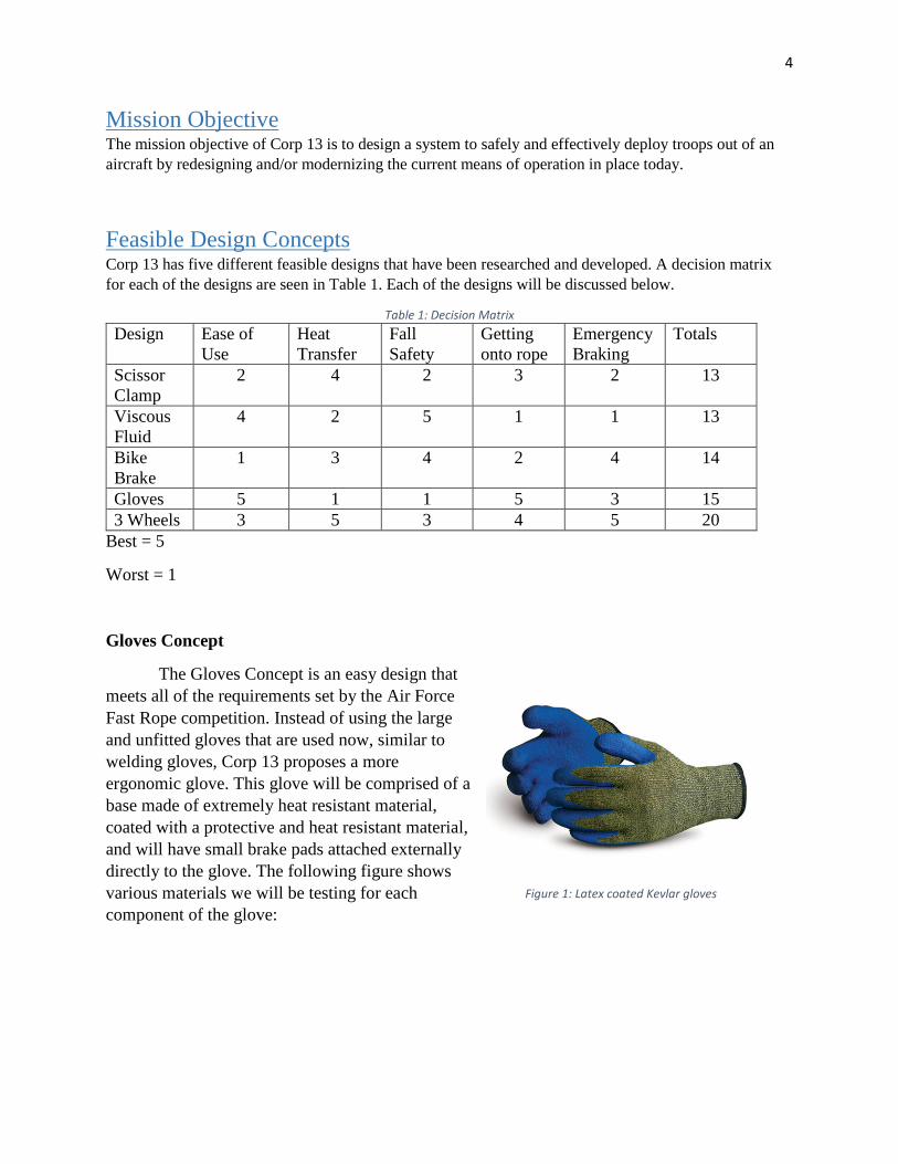
The Gloves Concept is an easy design that meets all of the requirements set by the Air Force Fast Rope competition. Instead of using the large and unfitted gloves that are used now, similar to welding gloves, Corp 13 proposes a more ergonomic glove. This glove will be comprised of a base made of extremely heat resistant material, coated with a protective and heat resistant material, and will have small brake pads attached externally directly to the glove. The following figure shows various materials we will be testing for each component of the glove:
Figure 1: Latex coated Kevlar gloves

5
Gloves
Base Material Inner Coating Brake Pads
Kevlar Latex Ceramic
Silicone Neoprene Carbon Ceramic
Nomex Silicone Non-Asbestos Organic
Figure 2: Component Decomposition and Testing Materials
Base Material
All of the base materials being tested can withstand extreme heat. Kevlar can withstand temperatures up to about 800°F. Silicone is often used for cookware and can withstand temperatures up to about 570°F. Nomex is a Dupont brand fiber that operates upwards of 500°F. Heat resistance is the ultimate goal for the base material of the gloves. While the base material is important, it does not provide any extra stopping force for the soldier. Additionally, Kevlar has low resistance to abrasion so would not be suited to be in direct contact with the rope.
Inner Coating
The inner coating would attempt to resolve this issue, but may not be necessary for base materials like silicone. The idea behind the coating is to provide extra resistance to wear, while also introducing another heat resistant material. Having another barrier of heat will reduce the chance of the soldier getting rope burn, even from greater heights.
Brake Pads
The intention of adding brake pad material to the outside of the glove is to provide more friction to the rope. The ideal brake pad would have a large friction coefficient and would not retain heat. Further testing is required to determine which material will fit this application the best. In addition, the brake lining will be cut into small pieces that fits each section of the hand to allow as much movement as possible, while retaining as much surface contact with the braking material as possible.

6
Material Selection
The Glove design required much more research than Corp 13’s other concepts. Research has been done on each component of the glove to choose the materials best suited for this application. Heat resistance, operating temperature, and abrasion resistance were all taken into consideration when finding base materials. Corp 13 met with Polymer and Fiber professor Dr. Broughton to find out about the most up to date fabrics available on the market. Materials like Vectran, Zylon, and Carbon Fiber were all researched in addition to those chosen for testing. The table below shows the overall score for each material:
Table 2: Glove Material Decision Matrix
Heat
Resistant
High Operating
Temperature Wear
Resistance Practical Ease of Acquisition Total Score
Kevlar ✓ 375°F 5 5 5 17
Carbon Fiber ✓ 900°F 1 2 4 13
Silicone ✓ 550°F 3 5 4 16
Nomex ✓ 400°F 5 5 4 18
Vectran ✓ 500°F 5 3 2 14
Zylon ✓ 1200°F 3 1 1 11
The scores were assigned by giving from one to three points for temperature, wear resistance, and ease of acquisition. One point was assigned for an operating temperature less than 400°F, two points were given between 400°F and 600°F, and three points were given if the operating temperature exceeded 600°F. Additionally, these scores were multiplied by two since this is the most important category for our design. Materials that were extremely wear resistant were given three points; those that did not perform well in this category were given one point. The Ease of Acquisition category is based on whether the material is easy to purchase in a form that would be simple to make into a glove. The most readily usable materials were given a 3,
Figure 3: Padded Glove

7
while the most difficult materials were given a one. Additionally, the Practical category took into consideration things that were not directly accounted for in the other categories. For example, Zylon is most commonly a thread. Therefore, it would be difficult to form an entire glove of this material. This category was given five points if the material was very practical for this application and one point if it was impractical. Thus, Kevlar, Silicone, and Nomex scored the best and were taken as the test materials for the base material. So far Corp 13 has ordered Mechanix gloves, silicone gloves, coated Kevlar gloves, ceramic brake pads, epoxy, and silicon to use as glue for this design.
Advantages o Requires no additional training o Requires no maintenance o Cheap o Easy to manufacture o Lightweight
Reusable
Disadvantages o Only meets minimum requirements o Descent rate still dependent on soldier o Not attached to rope
Scissor Clamp
The scissor clamp concept is based around using the weight of the rider to generate a clamping force around the rope. This clamping force will create a friction force opposing the motion of the rider and, thus, slowing down the rider to a safe landing speed. The idea is based off of the working principles of a scissor lift used in industrial lifting. Conventionally, the fixed end of and industrial scissor lift is attached to the end of the rope and the object being moved is clamped. In contrast to an industrial scissor lift, the object being moved (the person being lowered) in this concept would be attached to the fixed end of the clamp and the clamping would occur around the rope. The weight from the rider would cause the clamps to close in together and this would generate the friction force used to slow the descent. This set up essentially uses an inverted scissor clamp which can be seen in Figure 4. This, in principal, sounds simple at first, but several problems arise from this set up. First and foremost is the issue of the driving force behind a scissor clamp. When upright, gravity causes Figure 4: Scissor Clamp

8
the mass of the clamping arms to fold in on each other by rotating about their respective pins on the fixed end. When these arms swing together, their rotation about the central pin causes a clamping action. As the clamping occurs in this process, the central pin moves further away from the fixed end. When the clamp closes completely on itself, the central pin is as far away from the fixed end as it will possibly reach. The issue arises when the clamp is inverted. Gravity actually acts against the clamping motion. The weight of the arms tries to fold down and flat, opening up the clamp as wide as possible. This movement also pushes the central pin right up against the fixed end of the clamp. To fix this situation, an extra mechanism will be added to push out the central pin away from the fixed end. This essentially manually overrides the opening effect caused by gravity. With the pin pushed away from the fixed end, the clamp closes around the rope. This action will generate a friction force between the braking pads on the clamp and the rope, and this friction force will also help to keep the clamp closed. The friction force generated will slow down the rate of decent of the two clamping faces, but the fixed end of the clamp will still try to move down as it normally would. This causes the central pin and the fixed end to naturally move away from each other, further amplifying the clamping action. An added benefit of the scissor clamp set up it that the clamping force is proportional to the weight of the rider. Thus, a rider of a light weight and one of a heavy weight should experience the same rate of fall and braking without having to perform any changes on the setup of the system. With all of these things in consideration, Corp 13 recommends to continue to research and develop this idea and actively pursue it. Advantages
o Self-braking o Reusable o Allows for constant descent rate o Keep hands away from heat
Disadvantages
o Could be bulk/heavy o No good braking fail safe o Getting on rope will be complicated o Failure would result in complete detachment from rope
9
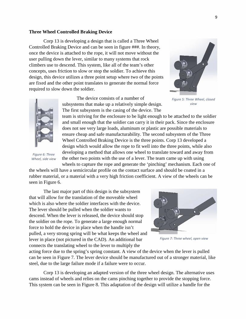
Three Wheel Controlled Braking Device
Corp 13 is developing a design that is called a Three Wheel Controlled Braking Device and can be seen in figure ###. In theory, once the device is attached to the rope, it will not move without the user pulling down the lever, similar to many systems that rock climbers use to descend. This system, like all of the team’s other concepts, uses friction to slow or stop the soldier. To achieve this design, this device utilizes a three point setup where two of the points are fixed and the other point translates to generate the normal force required to slow down the soldier.
The device consists of a number of subsystems that make up a relatively simple design. The first subsystem is the casing of the device. The team is striving for the enclosure to be light enough to be attached to the soldier and small enough that the soldier can carry it in their pack. Since the enclosure does not see very large loads, aluminum or plastic are possible materials to ensure cheap and safe manufacturability. The second subsystem of the Three Wheel Controlled Braking Device is the three points. Corp 13 developed a design which would allow the rope to fit well into the three points, while also developing a method that allows one wheel to translate toward and away from the other two points with the use of a lever. The team came up with using wheels to capture the rope and generate the ‘pinching’ mechanism. Each one of
the wheels will have a semicircular profile on the contact surface and should be coated in a rubber material, or a material with a very high friction coefficient. A view of the wheels can be seen in Figure 6.
The last major part of this design is the subsystem that will allow for the translation of the moveable wheel which is also where the soldier interfaces with the device. The lever should be pulled when the soldier wants to descend. When the lever is released, the device should stop the soldier on the rope. To generate a large enough normal force to hold the device in place when the handle isn’t pulled, a very strong spring will be what keeps the wheel and lever in place (not pictured in the CAD). An additional bar connects the translating wheel to the lever to multiply the acting force due to the spring’s spring constant. A view of the device when the lever is pulled can be seen in Figure 7. The lever device should be manufactured out of a stronger material, like steel, due to the large failure mode if a failure were to occur.
Corp 13 is developing an adapted version of the three wheel design. The alternative uses cams instead of wheels and relies on the cams pinching together to provide the stopping force. This system can be seen in Figure 8. This adaptation of the design will utilize a handle for the
Figure 5: Three Wheel, closed view
Figure 6: Three Wheel, side view
Figure 7: Three wheel, open view

10
soldier to release the pinched cams similar to the lever of the three wheeled device. The main difference in this design and the three wheeled design is that the cams will automatically grip the grope and will not require a spring to keep them closed. For the three wheeled design and the cam design, Corp 13 plans to outsource the manufacturing of the wheels, cams, and levers to Auburn University’s Design and Manufacturing Lab or a local machine shop to ensure a quick turnaround time so that testing can begin with this design very soon. So far, Corp 13 has ordered a Petzl Grigri 2 to help assist with the cam concepts for this idea.
In final consideration, this device is promising and would be simple, easy to manufacture, and very reliable. Corp 13 recommends that a mock up model be created to commence testing with the device in order to ensure reliability and the effectiveness of the spring to generate the normal force.
Advantages o Reusable o Easy to use o Controlled by user o Simple design
Disadvantages
o Descent rate still dependent on soldier o Many moving parts make error more probable o Could get very heavy
Viscous Fluid Braking System
This design is based on the principle of viscosity, a fluid’s resistance to flow. The design consists of two wheels that grip the fast rope on either side. One of these wheels is connected to a paddle wheel by a gear system. This allows the paddle’s motion to be fully driven by the wheels motion. The paddle is encased in a viscous fluid like mineral based, transformer oil so that the paddle has to flow through the fluid and the enclosure can be seen in figure 8. When the wheel begins to move as the person falls down the rope, the paddle begins to spin against the fluid, and the fluid resists the motion. As the paddle moves faster, the resistance it experiences increases. This system can be seen in figure 9. This sets the terminal velocity of the person or object falling to be much lower than typical terminal velocity, which can be worked out to be seven to nine feet per second at maximum. The shape of the paddle wheel and the viscosity of the fluid set the maximum velocity of the wheel. One issue with this design is that
Figure 9: Viscous Fluid Enclosure
Figure 8: Three Cam Braking System

11
the work done by the motion of the paddle wheel increases the fluid’s temperature. Viscosity is a temperature dependent property. Therefore, due to friction, the temperature of the fluid will constantly increase causing the person attached to fall faster. In addition, manufacturing tolerances would need to be very tight in order to allow the wheel to move while keeping the fluid contained. Tighter tolerances mean higher cost for this design compared to other considered concepts. Furthermore, this design would be heavier due to the contained fluids. The extra weight would mean a soldier would most likely not carry the device with him or her after a successful descent. Another drawback to the Viscous Fluid Braking System lies in interfacing the device with the rope. Corp 13 discussed a clamshell concept where the device would open up and latch into place around the rope. However, this idea would be challenging to accomplish due to the use of fluids within the device. While the Viscous Fluid concept is innovative, the many shortcomings of this design led Corp 13 to eliminate this as a potential design.
Advantages o Automatic braking (brakes with motion) o Can be hands free (attached by a harness, no need for hands to begin braking) o Keeps hands away from rope and heat sources o Additional safety of harness o Controlled speed of descent
Disadvantages o Work into the fluid will increase temperature of the fluid, changing the properties of the
fluid o Lack of an additional braking force in case of emergencies o Issues getting the device onto the rope o Cost of manufacturing o Manufacturing issues (having a device filled with fluid that moves perfectly) o Multi-variable analysis (partial differential equations drive the analysis) o Different weights fall at different speeds o Possibility of mechanical failure
Figure 10: Viscous Fluid Gear System

12
Bike Brake
One of Corp 13’s feasible options was the Bike Brake design. The design, seen in the Figure 8 below, operates on the concept of a hand brake from a bicycle. The concept would be adapted to fit the task at hand and would require the user to attach the mechanism to the rope in order to begin descent. During the fall the operator would be able to utilize a connected hand brake to achieve the desired descent rate. The hand brake would pull the attached wire which would clamp the brake pads onto the rope creating a friction force causing the user to slow down.
An advantage of the bike brake is the ability of the user to control his or her rate of descent. Regardless of starting height, the soldier would, in theory, be able to apply the force that he or she feels is necessary for the environment they are entering. Another advantage of this design is that the soldier would be physically connected to the device, which is connected to the rope. While not shown in the CAD concept designs, the next step in this design would be to create a chassis housing in which the braking system(s) would be contained. The chassis housing would also be the point of attachment for the soldier. Having the soldier attached to the rope provides another level of safety. In the event that the operator were to lose control of the rope, the soldier would still remain connected to the mechanism. Whereas, as the system stands currently, if a soldier’s hands slip off of the rope they are subject to serious injury. Figure 9 shows an architectural view of what the device would look like on the rope.
A disadvantage to this idea is creating enough force to actually control the descent. This design, as decided by Corp 13, is not a functional idea because the team believes the force generated by the braking mechanism will not be enough to adequately slow down or stop the operator. In theory, the idea works, but in reality we are not sure if the design is actually a functional idea. The braking system would need to be engineered from the ground up to provide the durability, reliability, and safety performance requirements.
Figure 11: Bike Brake
Figure 12: Bike Brake with rope

13
Product Decomposition: Bike Brake o Subsystem 1
• Braking Mechanism • Brake Pads
o Subsystem 2 • Chassis for mounting of braking system
o Subsystem 4 • Mechanism Housing
o Subsystem 5 • Connection between housing and fast roper
Advantages o Operator connected to rope during operation o Variable rate of descent o Quick attachment and removal o Operable in all weather conditions
Disadvantages
o Design may not generate adequate braking force to slow down the operator o Bike brakes could slip from rope during operation o Bike brakes could slip during certain weather conditions
Requirements 1. System must be safe
a. Fast Rope Operator must be connected to the rope in some fashion 2. Must be as compact as possible
a. Both weight and physical size should be considered 3. Must be able to accommodate a max load capacity of 450lbs 4. Descent rate should be between 7-8 ft/sec 5. Design should minimize amount of maintenance, sustainment, and support
a. Design should be easily repairable or replaceable if fix is necessary 6. Design should be quickly executable 7. Design should be quickly removed at end of descent 8. Design should be operable while wearing gloves 9. Easy to use 10. Design should be operable in all weather conditions 11. The BA SOF (Battlefield Airmen Special Operations Force) requires that the new design
must be as good as or better than the current expediency of the fast roping system. 12. The BA SOF must accept design

14
Concept of Operations For each method considered, the concept of operation for the system will follow a similar
path during a mission. The general sequence of steps that will need to occur during a mission will include:
1. The user will attach to the descending device before or during flight. 2. Just before drop, the user will connect the descending device to the rope or any other
medium connecting the aircraft to the ground. 3. The user will begin to descend by stepping off of the aircraft platform. 4. During the drop, the descending device will help allow the user to land safely on the
ground. 5. The user will detach from the rope or the descending device altogether. 6. Business will then be carried out on the ground as desired.
Every step in the above process can be achieved multiple ways.
In step one, the user must connect his body to the descending device in some fashion.
Most designs desire the user to connect using an existing harness system already used by the military to create support on the user’s body. The harness will most likely connect the system together via a carabiner. In the case of the gloves, they will simply be worn on the hands of the user. In step two, the entire system will be connected together at once. This will depend directly on the interface between the descending device and the rope. Every concept has a different method of applying this, but the goal of this operation is to be swift and easy. This crucial step will most likely be performed under duress while leaning over an exposed hatch of a hovering aircraft, so optimizing this interface is of great importance. Most mechanical braking systems will need a quick and simple way to secure the device to the rope, or could be preloaded on the rope which effectively changes the order that steps one and two will be performed. In the case of the gloves, this would just involve grabbing the rope.
For step three, the user will perform the standard technique taught by the Air Force on safely maneuvering out of the aircraft on to the rope. The exact body position of the user with the rope will be dependent on the geometry of the system interfaces. The center of gravity of a user connect by a harness will act differently than that of a user holding on with gloves. Step four is the main focus of the design challenge. The system will need to utilize a retarding force to oppose the natural downward motion generated by gravity. This force will need to be large enough to slow the descending speed to a rate safe enough for a person to land. This feature should also be adjusted to accommodate any extra weight in equipment the user may be carrying. This operation will likely use friction to generate this retarding force. The force could be a constant force, creating and regulating a new terminal velocity for the user as he falls. This force could also be varied, allowing the user to control the rate of descent as desired. For step five, a quick procedure is most desired. There are two options at hand to accomplish this task. The user could detach the descending device from the rope, or the user could remove his body from the descending device and leave it attached to the rope or out in the

15
field. To detach from the descending device, a quick release lever or pin will be used to achieve a swift separation. This leaves the user with the option to immediately stow the descending device or leave it attached to the harness and provide “action on objectives” if needed. To detach from the descending device a carabiner will be released freeing the user and leaving the device to be pulled back up with the rope after insertion or abandoned in the field depending on the device’s expendability. After a successful deployment, step six is where the Air Force carries out their mission on the ground as planned.
Validate and Verify Preliminary Testing
To test the prospective designs, Corp 13 developed a preliminary and final test set up. The preliminary test set up is comprised of a scaled down fast rope, a hanging pulley, a weight attached to one end of the rope, and a human operator on the other end of the rope that will be using the selected concept to slow down and stop the weight from falling. The rope used is similar to the fast rope employed by the military, but is scaled down to ¾” for use with the pulley. This set up provides opportunity for initial testing using each concept, but takes the safety risk for the operator out of the equation. Additionally, if there is a mechanical failure or high heat the operator can let go of the device with no negative safety repercussions. This test set up will allow the descent rate of the weight, heat of the product during and after, and ease of use to be measured. The performance of each concept will determine whether to move forward with the design or alter parts of the design to more effectively meet the mission objective. An additional benefit of this set up is how versatile the pulley allows the test to be. The test can be performed at the Auburn University Marine Ropes Course, in the Polymer and Fiber building attached to an I-beam, or even in the Senior Design Lab attached to a hydraulic crane. To perform this test, Corp 13 has ordered a Petzl Grigri 2, Sterling belay rope, four carabiners, webbing for a harness system, a ¾’’ 8-strand nylon rope, and a pulley.
Figure 13: Preliminary Test Set Up

16
Final Testing
The final testing will be performed at the Auburn University Marine Ropes Course. The test will be comprised of a full sized fast rope attached to the ropes course framing. To perform the test, a member of Corp 13 will attach themselves to the device and the rope and use the device to slow down and stop after jumping from an elevated platform. Safety will be of utmost importance during this test and will be accounted for by using a belay system and safety harness. Furthermore, the ground below the test set up will have additional safety features to pad the ground below.
Final testing will enable Corp 13 to ensure success of the chosen design at the Air Force Fast Rope Competition. This will also provide the opportunity to tweak the chosen design for any unforeseen obstacles during full-scale operation.
Interfaces All of the designs that have been mentioned in this report have an interface with the fast
rope. This is one of the largest challenges for Corp 13 due to the amount of time that it takes to attach a device to the rope, or the coordination that it would take to have a device already loaded onto the rope before the mission starts. Since time is of the essence and ease of use is a large requirement of the Air Force Research Lab, interfaces are very important to each of the aforementioned designs.
The easiest interface between the rope the potential devices is the rope and gloves. The gloves would require the least amount of time for the soldier to mount the rope, but also requires the most effort for the soldier. This interface sees high friction and would require great effectiveness of the product to ensure that the soldiers would not burn their hands. The other four designs have about the same amount of difficulty getting the device on the rope. Each one of the designs could be designed where the device needed to be preloaded on the rope and the solider would just walk up to it an carabiner in to position and then descend. However, this would require very extensive planning and the logistics of the process would be very difficult. Therefore, Corp 13 suggests that each of the devices should be attached to the rope by the soldier instead of preloaded onto the rope.
Figure 14: Marine Ropes Course

17
Another interface of the process is the device to the soldier. The soldiers are already wearing a harness when they descent with a D-ring that is attached to this harness. This D-ring will allow Corp 13 to design a way for the soldier to connect directly to the devices designed with a carabiner. A direct connection will increase safety of the process. The interface plan between these two items can be seen in Figure 12.
D-Ring Carabiner Descent Device
Figure 15: Interfaces
Mission Environment The fast rope is used in a variety of
environments. The insertion of troops using the fast rope can happen anywhere around the world, during any season. Because of the always-changing conditions this system is used in it needs to be practical in almost any environment. This includes rain, snow, sub-zero temperatures, limited visibility, extreme heat, and desert landscapes. The chosen concept needs to be operable in each of these conditions so the design needs to take into account such variable weather conditions. Fast roping will also frequently occur in combat scenarios, in which the operators can be subject to live fire from enemies. This stresses the importance of the simplicity and ease of using this device. An operator must be able to swiftly and safely use this device while under great duress. While fast roping is usually used to get soldiers onto the ground, it is also used to land soldiers on ships and submarines. Things like rust, dust, and humidity could affect the operation of the device and need to be taken into consideration in material selection. It is important for the chosen design to be extremely easy to attach to so soldiers can quickly get onto the ground even in unsafe conditions. Insertion of troops can happen anywhere from a secluded area to enemy territory so not only is safety of the design important, but also safety of the soldier. A product that is simple, efficient, and fast is necessary in these conditions.
?
Figure 16: Mission Environment

18
While the mission environment is important in designing a solution that will work in said environment, it is also important to consider what the team may be leaving behind. The effects of the design on the existing environment are also critical. If possible, the chosen design should be able to be stowed in the soldiers pack. This means a lightweight and small design. However, if the product cannot be stowed, it is important that it will not harm the given environment so this should be taken into consideration during material selection.
The settings the product will be used in are high stress require stealth. Therefore, designing based off of the mission environment is of utmost importance. Each of the proposed concepts takes into consideration the simplicity and practicality that is required for this application. Corp 13 believes that the suggested designs fit into the variable environments and are practical for soldiers to use for many tasks.
Risk Management Each possible idea comes with a slightly different set of risks and complications for
testing and future use. Overall testing complications include mechanical failure of the device, the potential energy hazard of having heavy weights and objects falling for testing purposes, difficulty of setting up a full scale test, and possible issues testing with a person using the device while falling. Most of these issues can and will be negating using a belaying system while testing. We will have at least one back up belay device at the end of the testing apparatus that will be used in the case of mechanical failure to stop the testing, as well as a safety if there is an issue with the dropping weight. The set up will be done using a safety ladder and multiple people checking for any issues. When we move to full scale testing, belay systems will be attached to the person using a harness, and will be used to ensure that there is no harm even in the case of complete failure.
The Auburn University Risk Management will be consulted before any full scale testing is attempted in order to ensure that our set up is as safe as possible.
All mechanical device designs have an issue with possible failure while getting onto the rope. We will be designing a safety latch system that will allow the device to be opened to get around the rope, and then close and the latch will secure the device to the rope.
The scissor clamp and viscous fluid braking devices both rely on proportional braking depending on the weight of the user, but do not include an additional method of increasing the braking force in case of an emergency. This is a design issue that will be discussed more later on, but we are currently discussing adding an emergency brake in addition to the main braking method.
The gloves pose other risks, including overheating and possible burns. This will be worked on, with the addition of insulating material in between the user’s hands and the rope. Also, the gloves do not ensure that the user will not slip off of the rope, but we will be designing brake pads for the gloves that will have a higher coefficient of dynamic friction to make staying on the

19
rope easier. To ensure that the brake pads stay on the gloves without ripping off, high temperature epoxies will be used to adhere the brake pads to the glove material.
Other possible safety issues may come up, and will be discussed among the group members, the technical advisor, and the university risk management team.
Configuration Management The team utilizes Googles’ Google Drive system for all storage of CAD, informative
documents, and other team related materials. The drive is frequently updated with the team’s current documentation and is accessible by all members of the group.
Project Management Organization
Corp 13 is organized into a corporate-like structure. The team has an accountant, a manager, an assistant manager, a secretary, and lead engineer. Tasks are assigned based on the area in which the tasks requires attention. For example, if the lead engineer receives a design from another member of the team that requires some parts to be ordered, then he will pass the responsibility along to the accountant. All members were required to submit initial designs for brainstorming, and each member continues to support the ongoing process of designing regardless of their assigned duty. The roles of the team are as following:
Manager – Caleb Clemons
Assistant Manager – Logan Brost
Accountant – Meredith Jones
Lead Engineer – Jake MacKay
Scribe – Ric Gilliland
Schedule
09/04/2015 - Initial Designs Due
10/05/2015 - Bill of Materials for Contending Designs Due
10/22/2015 - Concepts Review
11/5/2015 - Initial Prototypes Assembled and Testing
12/04/2015 - Preliminary Design Review

20
Project Costs (Estimate)
Testing Methods and Material - $500
Prototypes for Each Design(x5) - $200($1000)
Material for Final Design - $1000
Trip to Ft. Walton - $500
Alternative Materials - $1000
Trip to Competition - $5000
Estimated Costs - $9000
Tasks and Goals for Next Review
Tasks o Develop Prototypes for each proposed design o Test prototypes from proposed designs o Collect data from testing o Continue to research ways to improve each design
Goals
o Combine back with the other part of Corp 13 to more effectively and efficiently test and develop designs
o Narrow down to two different designs and host a review with the AFRL to select the final design

21
Purchases
Table 3: Bill of Materials
Glove Construction
Item Vendor Grainger Price Number Price/Item Total Price/Unit Mechanix gloves Amazon $28.15 1 $14.92 $14.92 Silicon Gloves Walmart N/A 2 $5.99 $11.98 Epoxy Home Depot $8.05 1 $5.67 $5.67 Silicon Glue Home Depot $12.52 1 $6.24 $6.24 Coated Kevlar Grainger $36.45 1 $36.45 $36.45 Brake Pad (ceramic)
Walmart N/A 1 $35.57 $35.57
Nomex Gloves Amazon $110.80 1 $25.67 $25.67 Friction Material McMaster Carr N/A 1 $45.26 $45.26
Large Scale Testing Construction
Item Vendor Grainger Price Number Price/Item Total Price/Unit Petzl Grigri 2 Amazon N/A 1 $79.96 $79.96 Sterling Rope Evolution (70m)
Amazon N/A 1 $216.16 $216.16
Carabiner Amazon N/A 4 $11.25 $45.00 Webbing (120 cm)
Amazon N/A 3 $9.36 $28.08
Rope (80ft) Knot and Rope N/A 1 $108.00 $108.00 Pulley McMaster Carr $131.75 1 $114.34 $114.34
Total (Before Tax) $773.30 Sales Tax (9%) $69.60 Total $842.90

22
Conclusions In conclusion, after reviewing all proposed concepts, the two most feasible and practical systems to pursue are the redesigned glove system and the three wheeled controlled braking device. These design will most completely and competitively meet the requirements set forth by the AFRL as well as serving as a practical tool that could one day be implemented during combat operations. The gloves provide the simplest solution, requiring no new training or maintenance and needing only small monetary investment. The three wheel system provides the safest option and is potentially the most effective option. Moving forward, these concepts will be further developed, built, and tested. While these two are recognized as the most promising options, other options are not all being thrown out. Before the next review, prototypes will be constructed and tested for the gloves, three wheel device, and potentially for other concepts as well. The information gathered from the testing will help Corp 13 develop a direction for the final product to be taken to the AFRL competition.